Article

Steel Beam-to-Column Friction Joint under a Column Loss Scenario

by
Roberto Tartaglia
1,*,
Roberto Carlevaris
2,
Mario D’Aniello
2 and
Raffaele Landolfo
2
1
Department of Engineering (DING), University of Sannio, Piazza Roma, 82100 Benevento, Italy
2
Department of Structures for Engineering and Architecture, University of Naples Federico II, Via Forno Vecchio, 80134 Naples, Italy
*
Author to whom correspondence should be addressed.
Buildings 2024, 14(3), 784; https://doi.org/10.3390/buildings14030784
Submission received: 29 January 2024 / Revised: 11 March 2024 / Accepted: 12 March 2024 / Published: 13 March 2024

Abstract

:
FREEDAM joints have been recently seismically prequalified for applications in European seismically prone countries. Despite their excellent seismic response, FREEDAM joints are not purposely conceived for exceptional loading conditions, such as in the case of a column loss scenario. Therefore, a comprehensive parametric numerical study has been carried out to investigate the robustness of this type of joint, varying the geometry of the beam–column assembly and the associated friction device. The results of the performed finite-element simulations allowed the identification of the critical components of the joints such as the upper T-stub connecting the upper beam flange to the column. This component is characterized by significant demand, due to the concentration of tensile and shear forces when catenary action develops in the beam. In order to enhance the ductility of the beam-to-column joint under large imposed rotations, the details of the upper T-stub connection were modified and numerically analyzed. The obtained results allowed for the verifying of the effectiveness of the amended details as well as characterizing the evolution of the tensile forces in the bolts.

1. Introduction

Seismic-resistant steel structures are designed to dissipate the earthquake’s incoming energy by means of plastic deformations in ductile elements (i.e., beams, braces, and links, depending on the structural type) [1,2,3]. However, the repair costs in the aftermath of a severe earthquake are very high, and in many cases the more cost-effective option is to demolish the entire structure and rebuild it. To overcome this problem, many studies were recently carried out to develop resilient low-damage structures to quickly restore the structure’s full functionality [4,5,6]. Such a design goal can be reached by localizing the damage in the friction devices (also called “friction dampers”), which are mindfully designed for this purpose and which are easily replaceable after the catastrophic event. In the last thirty years, the effectiveness of these mechanisms has been widely proven. In the early 1990s, Grigorian et al. [7] tested slotted bolted connections with friction devices, which were made of mill scale steel and brass shims. Comprehensive studies were conducted by New Zealand researchers such as Butterworth and Clifton [8], Borzouie et al. [9], Khoo et al. [10,11,12,13], and MacRae et al. [14], who mainly focused on dissipative joints with unsymmetric friction devices. Lee et al. [15,16] used slotted bolted connections (SBCs) made of mild steel and composite material derived from the automotive breaking technology. Zhai et al. [17] studied hybrid damping systems that couple the energy dissipation given by friction with the one given by plasticization of steel strips. Nowadays, friction dampers are still a cutting-edge research topic, and several researchers are investigating their use in a variety of structural systems, such as precast members (Qian et al. [18]) and staggered-truss framing systems (Zhou et al. [19]).
In Europe, joints with symmetric friction dampers were studied and seismically prequalified within the FREEDAM and FREEDAM+ research projects [20]. The joints with FREEDAM devices were designed as full rigid partial-strength joints to be installed at the beam ends of steel moment-resisting frames (MRFs).
The seismic effectiveness of the FREDAM joints was verified through a wide range of experimental, numerical, and analytical studies [21,22,23,24,25].
Some preliminary experimental and numerical studies have also been performed to investigate the response of FREEDAM joints against accidental loads, such as impact and column loss. In particular, the column loss scenario represents one of the more common accidental load conditions, and it consists of the sudden removal of a column of the structure. D’Antimo et al. [26,27] and Golea et al. [28] highlighted the fact that the upper T-stub connecting the beam flange to the column can be the critical component limiting the ductility of the joints. However, due to the exiguity of experimental data, the ultimate response of FREEDAM joints under column loss conditions needs to be further investigated, as is also highlighted in [29]. The rotation demand of FREEDAM joints can be rather high in the case of column loss conditions. Golea et al. [29] performed the robustness assessment on seismically designed 20 MRFs and D-CBFs under a Eurocode-compliant column loss scenario, showing that the rotation demand can largely exceed 0.10 rad. In addition, their analytical and numerical studies demonstrated that the demand for robustness may require different details of the joints initially tailored for seismic performance.
Although many studies have been conducted to provide design rules and proper detailing of different types of beam-to-column connections, the case of FREEDAM joints is not adequately covered. Due to the specific features of FREEDAM joints, the details of the parts constituting the connection should be amended to resist the catenary effects imposed by the beam in the case of large rotations but the seismic efficiency of the joint should be guaranteed. Therefore, any type of strengthening intervention should be conceived in order to allow the relative rotation between the beam and column so that the friction pad can slide into the lower connection under seismic conditions while avoiding any premature failure and enhancing the resistance and rotational capacity to ensure the robustness of the structure. Based on the authors’ best knowledge, this aspect is not yet solved.
Therefore, this consideration motivated the study summarized in this paper, which was aimed at investigating the resisting mechanism of the FREEDAM joints when catenary action develops in the beam, as a result of a column loss scenario. In addition, ad hoc details were studied to enhance the ductility of the upper T-stub connection of these joints. Therefore, refined finite-element (FE) analyses were carried out using FE models properly calibrated against the experimental results conducted within the FREEDAM project. Hence, this study proposes a slight modification of the prequalified FREEDAM upper T-stub, in order to widen the application of the FREEDAM connection to include also the column loss scenario.
The paper is articulated in five parts: (i) in the first part, the prequalified FREEDAM joints are briefly described; (ii) in the second part, the enhanced details of the upper T-stub connection are shown; (iii) in the third part the validation of the FE models is shown; (iv) the fourth part shows the comparison between the original and enhanced joints; and (v) the last part summarizes the main conclusions.

2. The Investigated Beam-to-Column Joints

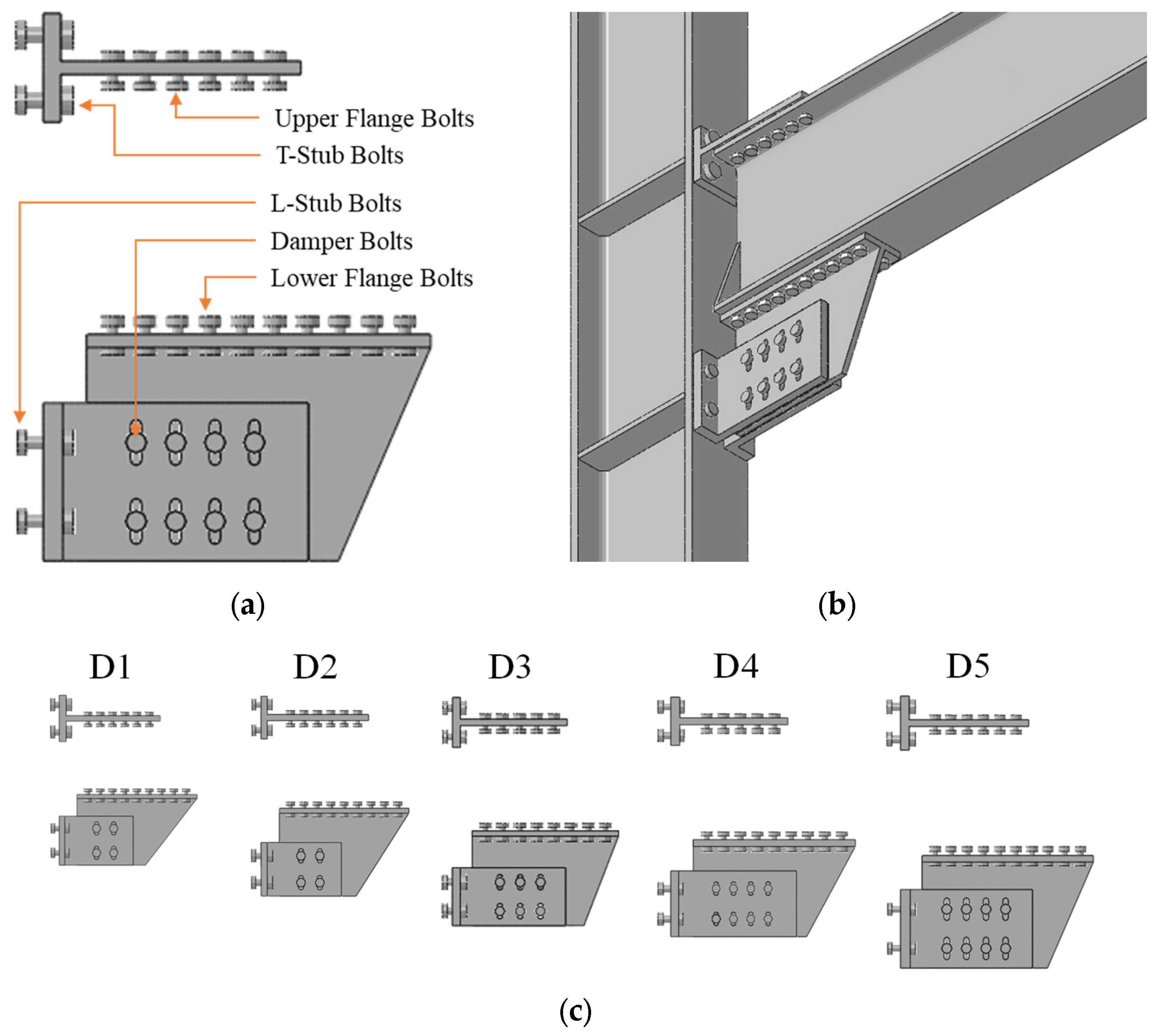
2.1. The Seismically Prequalifed FREEDAM Joints

The FREEDAM joints are equipped with a friction device located at the lower flange of the beam, while the upper beam flange is connected to the column flange using a bolted T-stub connection (see Figure 1a,b). As explained in detail by Latour et al. [21], the friction device can be arranged with either vertical or horizontal sliding. In the first case, the friction mechanism is guaranteed by a vertical gusset plate (hereinafter referred to as the “rib”), which is connected to the lower beam flange and is equipped with friction shims, one-per-side of the rib, which constitute the source of dissipation. The rib and shims are clamped together, employing L-stub connections, and then to the column flange. The sliding between the clamped surfaces is guaranteed by specifically designed slotted holes (see Figure 1a).
The rotational capacity of the connection depends on the length of the slotted holes, while the rotation center of the connection is located in the unrestrained length of the stem of the upper T-stub, close to its flange. The tightening of the bolts clamping the device is calibrated to reach the design resistance of the connection. To make the FREEDAM system suitable for a wide range of beam and column steel profiles, five devices have already been designed (named D1 to D5) within the prequalification phase of the FREEDAM project [20] and are numerically investigated by Tartaglia et al. [24]. These devices differ one from the other, based on the geometric dimensions of each component and the nominal diameter of the bolts.
Figure 1c depicts devices D1 to D5 without the connected structural elements, while the main features of the selected FREEDAM assemblies are summarized in Table 1. These assemblies differ from each other based on the device in use, the connected structural elements, and the lever arm of the bending-moment resistance.
FREEDAM joints are designed as full rigid partial-strength joints. The design bending resistance of the connection can be estimated as in Equation (1), as:
M R d , j = μ d y n F p , C , d n b n s h s
where:
μdyn is the characteristic dynamic friction coefficient of the friction pads;
Fp,C,d is the preload force for the damper bolt, in long-term condition;
nb is the number of damper bolts;
ns is the number of shear surfaces;
hs is the lever arm of the connection, namely the distance between the centroid of the bolts in the friction device and the stem of the upper T-stub connection.
Each FREEDAM device is suitable for a certain range of steel profiles, mostly IPE for the beams and HE for columns and, based on [16], the required device resistance MRd,j is usually in the range of 0.30–0.60 times the plastic resistance of the connected beam Mpl,Rd,beam, as in Equation (2):
M R d , j = m M p l , R d , b e a m   where m   =   0.30 0.60
Therefore, once the profiles, the dampers and the m parameter are set, the design preload force for the bolts of the friction damper bolts is given by Equation (3):
F p , C , d = m   M p l , R d , b e a m μ d y n n b n s h s
The preload force must be selected within the range of 0.4–0.8 times the values recommended by EN 1993-1-8 [30].

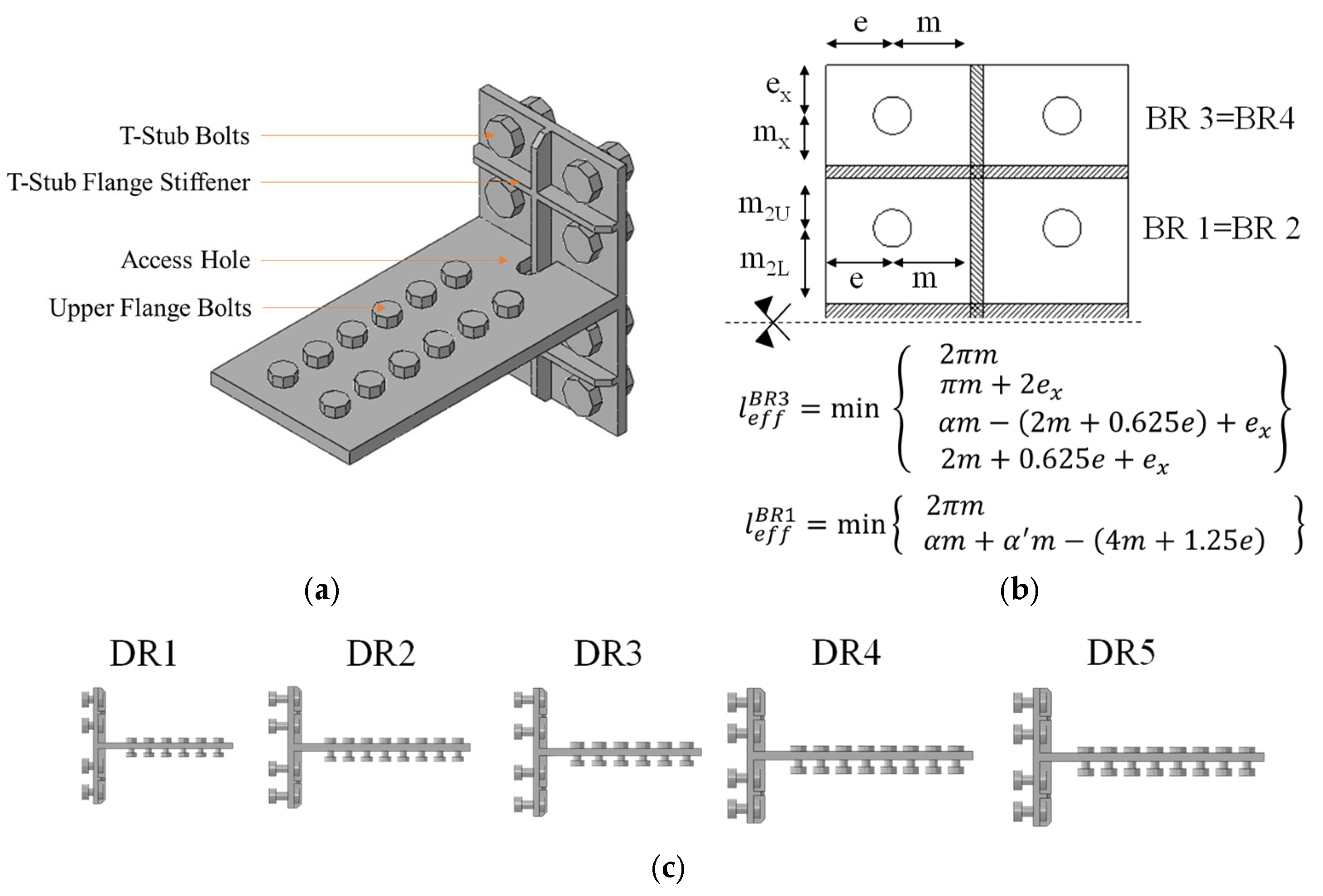
2.2. The Revised Detail to Enhance the Ductility of the Joint

The details of the upper T-stub connection were modified in order to increase the ductility of FREEDAM joints under column loss conditions. As can be observed in Figure 2, the ameliorated connection is characterized by two additional bolt rows, and the flange was specifically stiffened (see Figure 2).
The new T-stub configuration was designed to obtain a ductile failure (i.e., mainly mode 1). The resistance of this connection was evaluated by means of the component method, where the yield line pattern was evaluated by Latour et al. [31] and Demonceau et al. [32], who proposed analytical formulations for the cases of T-stub connections with four bolts.
In order to improve the efficiency of the bolt rows, both horizontal and vertical stiffeners (with a constant thickness equal to 15 mm) were adopted (see Figure 2) and their associated effective lengths were derived, in accordance with P398 [33]. An access hole was also designed to limit the stress concentration between the vertical stiffener and the stem of the T-stub (see Figure 2a).
The ameliorated T-stubs were designed to resist at least 40% of the beam tensile plastic resistance (0.4Npl,R), which was assumed as the expected value of the catenary action in the beam [34].
The response of the joints with the enhanced details was also investigated for different beam–column assemblies equipped with the five devices previously shown in Figure 1b. The main features of the enhanced upper T-stub connections are shown in Figure 2a–c and are quantitatively reported in Table 2 for this additional set of joints, which are identified as DR1 to DR5.

3. Finite-Element Modelling

3.1. Modelling Assumptions

FE simulations have been carried out using ABAQUS 6.14 [35]. The geometry of the modeled beam–column assemblies has been extracted from a reference building with an inter-story height equal to 3.5 m and span length of 7.5 m, as in [19,20], thus leading to a column height equal to 3.5 m and the beam mid-length equal to 3.75 m. The assumed boundary conditions are shown in Figure 3a and are consistent with the type of imposed loading scenarios, namely an axially unrestrained beam to investigate the hogging and sagging responses for seismic-like loading conditions, and an axially restrained beam for the column loss scenario. Moreover, the beam was subjected to lateral–torsional restraint by fixing the lateral displacements in a discrete number of sections along the beam length, according to EN 1993-1-1 [36].
All parts were discretized using the C3D8R solid-element type (i.e., 8-node linear brick, reduced integration), since this can guarantee a good balance between saving computational cost and satisfactory results. Locking phenomena are already avoided by the nature of the element, while hourglass control is adopted during the element definition. The mesh density was defined based on sensitivity analyses performed by authors in [19,20]. In particular, plates and bolts were discretized using a mesh with an average dimension of 5 mm per side, while the average dimension of the other elements was set as equal to 20 mm (see Figure 3b), as validated in previous studies [21,24,25,34].
All the steel parts were made of S355 steel grade, with an elastic modulus of 210,000 MPa and Poisson’s ratio of 0.3. The bolts were 10.9 grade, modeled according to previous studies performed in [37]. The steel non-linear behavior was modeled using true stress-true strain curves derived by experimental coupon tests, while the materials’ non-linearity was modeled by using the von Mises yield criterion with combined isotropic hardening.
Clamping of the bolts was applied as “bolt load” on the shanks in the load module. The magnitude for generic bolts is given by EN 1993-1-8 [30], while the value for the bolts of the damper depends on the design resistance of the joint and is calculated according to Equation (3) of the design procedure. Geometric non-linearity of large displacements is taken into account by switching on, for every step, the corresponding command “Nlgeom” in the step module. The loading history is applied at the beam tip.
Contact between elements’ surfaces was modeled using “contact interaction” with a “penalty” friction formulation as tangential behavior, and with “hard contact” as normal behavior. Two different contact interaction properties were modeled: one for the generic steel-to-steel contact, with a friction coefficient equal to 0.3, and the other one for the contact between the steel parts and the friction shims, with a friction coefficient equal to 0.53, as defined by Latour et al. [16]. Full penetration welds were modeled using tie constraints, while “rigid body” constraints were adopted to introduce the boundary conditions.
Under the column loss scenario, an additional external axial restraint was added at the beam extremity for the development of the catenary actions (see Figure 3a).
The seismic and column loss-like loading was simulated by imposing a displacement history at the beam tip. Dynamic implicit analyses with quasi-static control were performed by using the Abaqus/CAE 6.14 Standard Implicit Dynamic solver.

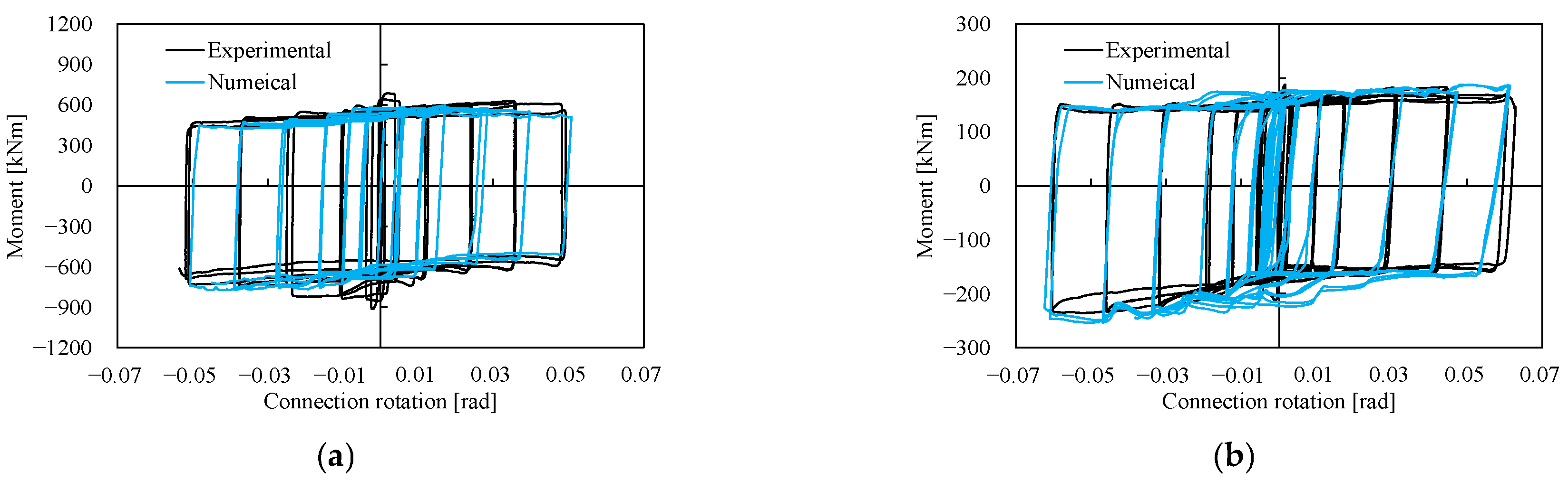
3.2. Validation of the FE Model

The effectiveness of the adopted modeling assumptions was verified against the experimental tests performed in the Department of Civil Engineering at the University of Salerno within the FREEDAM research project [21]. In particular, among the performed tests, two beam-to-column assemblies were numerically calibrated:
  • Experimental specimen 1: with IPE 270 as beam and HE 220 M as column;
  • Experimental specimen 2: with IPE 450 as beam and HE 500 B as column.
Figure 4 depicts the comparison between the experimental tests and FE simulations in terms of moment–rotation curves. As can be observed, the FE models satisfactorily match both the elastic stiffness and the resistance of the tested joints.

4. Results of Parametric FE Simulations

4.1. Performance of the Reference FREEDAM Joints

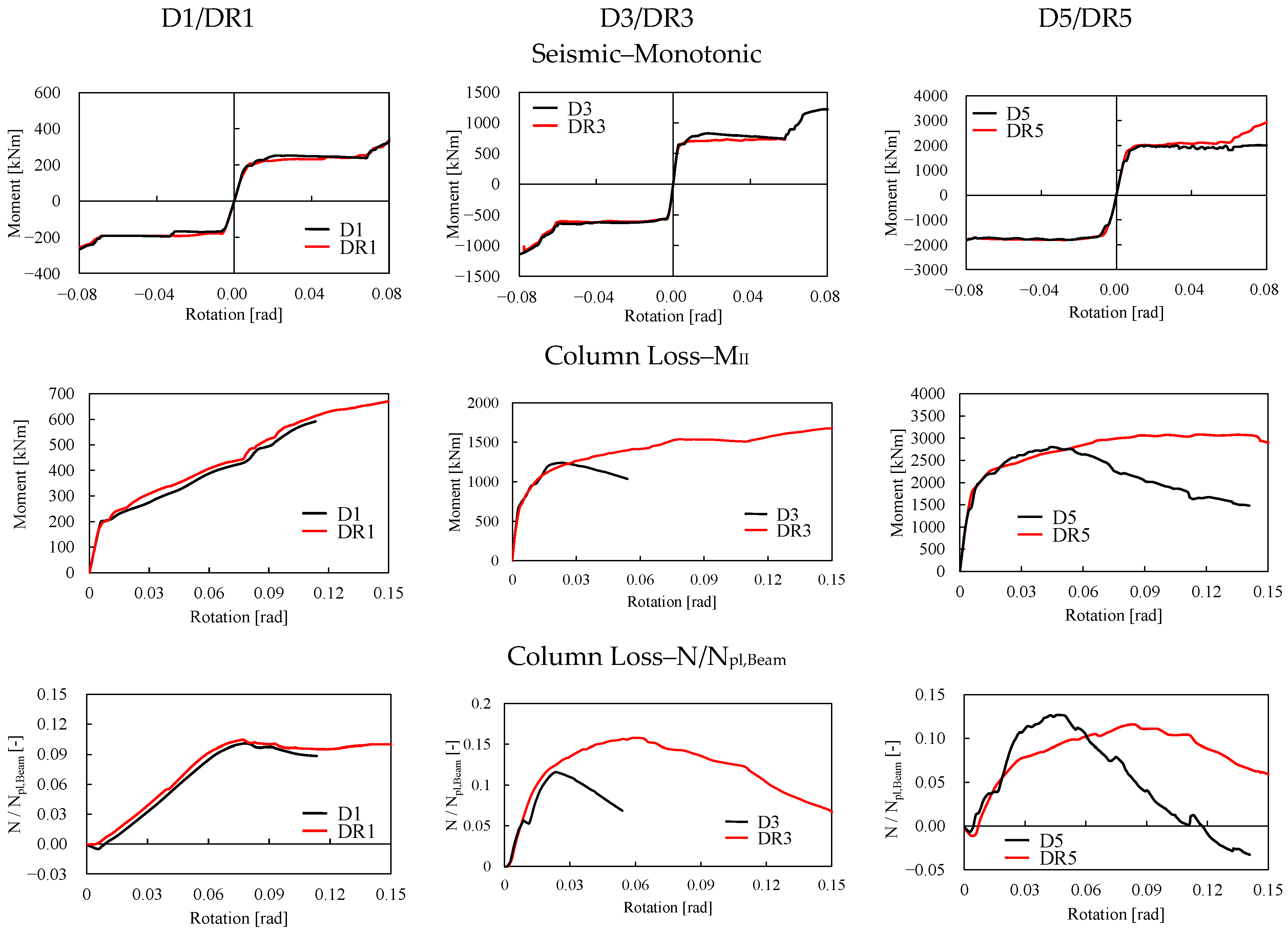
4.1.1. Response under Monotonic Loading

Figure 5 and Figure 6 show the results of all the investigated devices in terms of moment–rotation curves and von Mises stress distribution, respectively. As it can be observed, under both hogging and sagging moments, the moment–rotation curves present an initial linear response (up to 0.01 rad); then, increasing the rotational demand, a horizontal branch, close to the design bending moment, can be observed up to 0.06–0.08 rad (in the function of the investigated configuration), which corresponds to the closure of the stroke of the friction damper. Once the bolts of the friction device are in contact with the edge of the slotted holes of the rib, the resistance of the joints increases.
The joint response is not symmetrical. The hogging moments are slightly greater than the expected resistance, while the sagging response is almost equal to the design value. This aspect was also observed by [21,24] and it can be explained by the different deformability of the lower components of the connection concerning the direction of the imposed rotation (i.e., L-stubs that enclose the friction device), which modify the resisting lever arm of the joint. When the joint is subjected to a sagging bending moment, the L-stubs are affected by tensile force and they are more prone to open up, with a detrimental effect on the overall performance of the friction device. As a consequence, the hogging-moment resistance is about 25% greater than that of the sagging at a chord rotation equal to 0.04 rad.

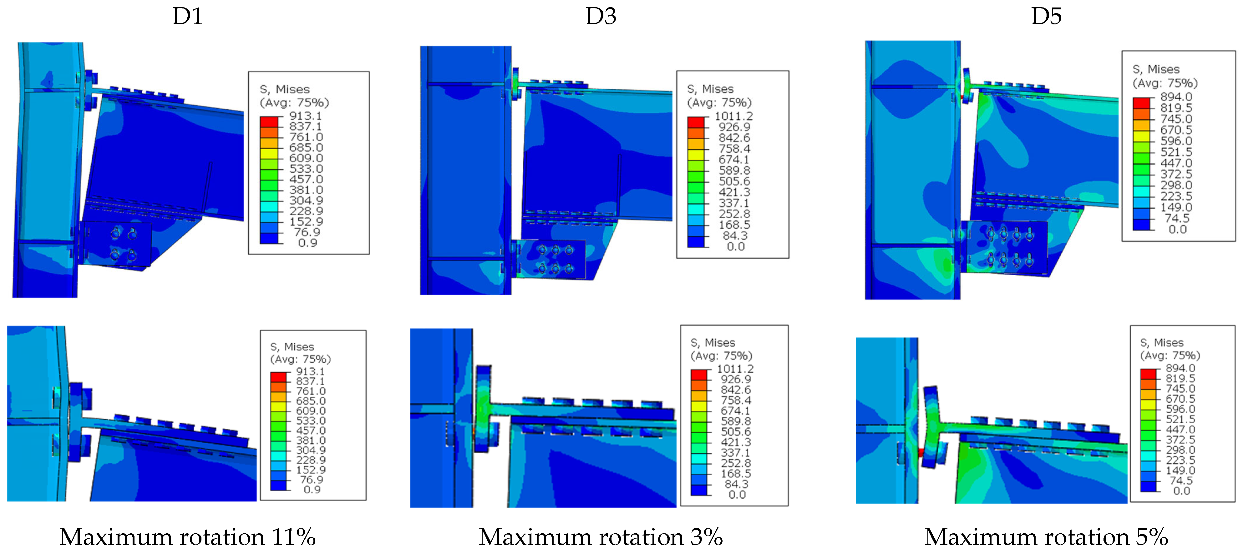
4.1.2. Response under Column Loss Scenario

In the column loss scenario, the behavior of the joint is investigated when a column adjacent to the investigated joints is removed. The development of catenary action in the beam generates bending effects that affect the second-order bending moment (MII), as specified in Equation (4):
M I I = M I N d         M I I = V L N d
where MI is the first-order bending moment, V is the vertical force acting at the tip of the modeled beam (i.e., the equivalent mid-span of the reference building), L is the chord beam length (measured from the column axis), N is the catenary force in the beam, and d is the vertical displacement applied at the beam tip.
Figure 7 depicts the comparison between the flexural responses due to the column loss and the seismic-like condition of the D1, D3, and D5 joints, respectively, as well as the evolution of the catenary action, normalized to the beam tensile resistance (Npl,Beam), with the imposed rotation.
As can be observed, the flexural responses in the elastic range of two investigated loading scenarios (i.e., seismic and column loss) coincide (i.e., the same elastic stiffness). However, for an increasing value of rotation, the development of the normal action within the assemblies provides an increase in resistance of the connections, which overcomes the design resisting moment.
In the non-linear range, namely under large deformations, significant differences can be observed because of the tensile-force demand in the upper T-stub connection, which also differs from the beam–column assembly (see Figure 8). The D1 assembly shows a ductile behavior, allowing the formation of plastic deformation within the column, while the upper T-stub connection remains almost in the elastic range. Contrariwise, both D3 and D5 show less ductility because of the premature tensile failure of the bolts of the upper T-stub. This type of behavior is mainly due to the influence of beam size. The joints with deeper beams do not exhibit the plateau corresponding to the activation of the friction resistance of the device, as in the case under seismic loading. The deeper beams develop a strut-and-tie mechanism that locally modifies the distribution of effects in the upper and lower connections [24,25].

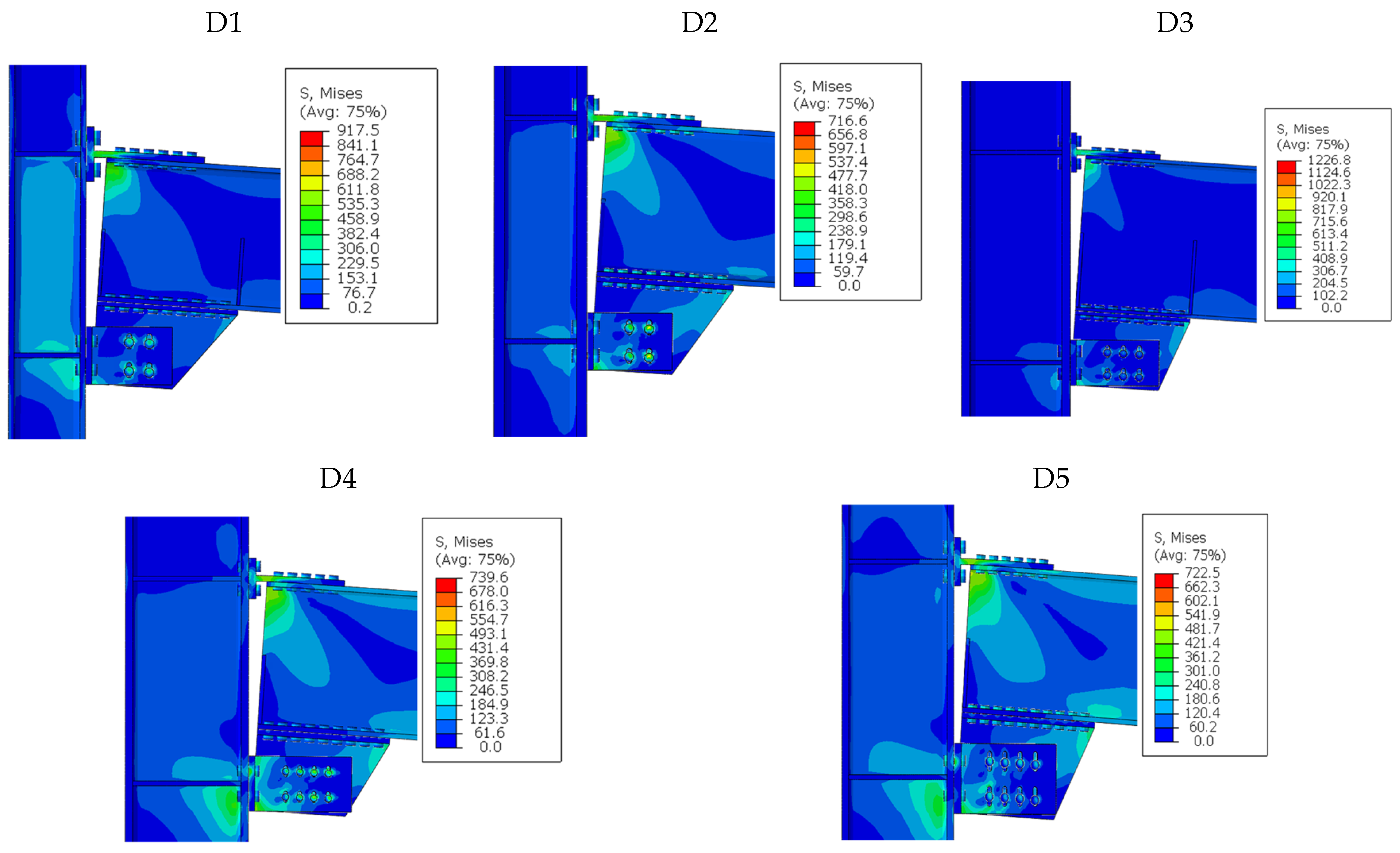
4.2. Performance of the Joints with the Enhanced Details

Figure 9 depicts the comparison between the original FREEDAM joints (i.e., D1 to D5) and the corresponding ones with the enhanced details of the upper T-stub connection (i.e., DR1 to DR5) in terms of moment–rotation curves under both monotonic loading and column loss scenario. In addition, the evolution of the catenary action in the beam is shown for the robustness of the loading condition. The damage pattern and the corresponding von Mises stress distribution for the enhanced joints under the column loss scenario are shown in Figure 10.
The comparisons of seismic-like conditions confirm that both the sagging- and hogging-moment response curves of the joints are not appreciably affected by the ameliorated details of the upper T-stub connection. In the case of assemblies with an intermediate beam (i.e., D3 and DR3), the strengthened joints exhibit a smoother plateau in the enhanced joint under seismic loading. This behavior is due to the greater relative rigidity of the upper T-stub connection, which allows for keeping the resisting lever arm of the joint. However, this finding cannot be generalized to other assembles.
Significant differences are observable in the case of the column loss scenario. The DR joints exhibit higher ductility and ultimate rotation than those achievable by the corresponding unstiffened ones (see Figure 9). The greater resistance of the upper T-stub allows for keeping the resisting lever arm of the joint that can transfer the moment at large rotations. It is worth noting that the catenary actions do not substantially increase in the DR joints, because their magnitude mainly depends on the beam deformations. However, the catenary effect can be resisted at greater rotations than those achievable by unstrengthened joints. The comparison between Figure 8 and Figure 10 highlights the different localization of damage under column loss conditions. The damage pattern of the unstrengthenedd joints is characterized by the premature failure of all bolts of the upper T-stub connection. On the contrary, the use of shallow rib stiffeners of the T-stub flange allows for greater ductility as well as the resisting contribution of the added bolt rows, which are crucial for balancing the tensile force when the flange is fully opened. These results confirm the effectiveness of the designed details. The additional bolt rows, as well as having the designed flange of the T-stub to develop a failure mode 1 (see also Figure 10), allow for the postponing of the failure of the connection and for increasing its ultimate deformation, thus increasing the overall joint rotation. In this regard, Figure 11 shows the evolution of tensile force in the bolt rows (BRs) with the applied rotation. It can be observed that for low levels of rotations (when the upper T-stub connection is in the elastic range), the external bolts do not provide any contribution to the T-stub resistance. On the contrary, by increasing the imposed rotation, the inner bolts develop high plastic deformations and the external bolts contribute to the resisting mechanism of the connection by up to 10% of rotation.
For instance, it can be observed that the inner bolts (Bolt Row 1 and Bolt Row 2) of DR3 exhibit a substantial increase in tensile force, while the preload in the external rows (Bolt Row 3 and Bolt Row 4) decreases. This reduction in the preload is mainly due to the contact forces that develop between the flange of the upper T-stub and the column, which are higher for the outermost bolt rows as a consequence of the gap opening between the T-stub flange and the column face. Of course, the latter phenomenon is mainly counteracted by the inner bolt rows. At the higher rotations (i.e., more than 0.15 rad), the failure of the Bolt Rows 1 and 2 and the consequent engagement of the external bolts can be observed (see Figure 10).

5. Conclusions

FREEDAM joints are characterized by a very ductile and stable behavior under monotonic and seismic loads, thanks to the control friction resistance and stable slippage in the replaceable friction dampers. However, these joints do not provide a ductile response when subjected to a column loss scenario, mainly due to the premature brittle failure of the upper T-stub connection. Therefore, in the present work, modified details of this connection have been designed to enhance the ductility of FREEDAM joints under the column loss scenario and have been investigated by means of finite-element simulations.
Based on the obtained results, the following conclusions can be drawn.
  • Under column-loss loading conditions, the ductility of FREEDAM joints is limited by the brittle failure of the bolts of the upper T-stub connection. The catenary action developing in the beam induces significant tensile forces in the upper T-stub connection, which exceed the resistance of the bolts.
  • To enhance the response of the joints, the details of the flange of the upper T-stub were ameliorated by introducing two additional bolt rows (one-per-side of the stem) and a grid of stiffeners to restrain the pattern of the yield line and to promote failure mode 1 of the flange.
  • The finite-element analyses showed that the ductility and ultimate rotation of the joints with the designed details can exceed a rotation of 0.15 rad, thus substantially improving the response of the considered beam–column joints under column loss conditions.
  • In the case of seismic-like loading, the response of the joints with the ameliorated details is substantially the same as the original FREEDAM joints.
  • Additional experimental and numerical studies should be performed to assess the improvement of the contribution to the resisting mechanism of the additional bolt rows in the function of the local detailing of the stiffeners.

Author Contributions

Conceptualization, R.T., R.C. and M.D.; methodology, R.T., R.C. and M.D.; software, R.T. and R.C.; validation, R.T., R.C. and M.D.; formal analysis, R.T. and R.C.; investigation, R.T., R.C. and M.D.; resources, R.L.; writing—original draft preparation, R.T., R.C. and M.D.; writing—review and editing, R.T., M.D. and R.L.; supervision, R.T. and M.D.; project administration, M.D. and R.L. All authors have read and agreed to the published version of the manuscript.

Funding

This research received no external funding.

Data Availability Statement

Data is contained within the article.

Acknowledgments

The authors sincerely thank the European Commission within RFCS Research & Innovation, which supported the research activity herein presented by the following research grants: RFSR-CT-2015-00022 and n. 899321.

Conflicts of Interest

The authors declare no conflicts of interest.

References

  1. Elghazouli, A.Y. Assessment of European seismic design procedures for steel framed structures. Bull. Earthq. Eng. 2010, 8, 65–89. [Google Scholar] [CrossRef]
  2. Nastri, E. Design and assessment of steel structures in seismic areas: Outcomes of the last Italian conference of steel structures. Ing. Sismica 2018, 35, 1–4. [Google Scholar]
  3. Tartaglia, R.; D’Aniello, M.; Landolfo, R. Seismic performance of Eurocode-compliant ductile steel MRFs. Earthq. Eng. Struct. Dyn. 2022, 51, 2527–2552. [Google Scholar] [CrossRef]
  4. Fang, C.; Wang, W.; Qiu, C.; Hu, S.; MacRae, G.A.; Eatherton, M.R. Seismic resilient steel structures: A review of research, practice, challenges and opportunities. J. Constr. Steel Res. 2022, 191, 107172. [Google Scholar] [CrossRef]
  5. Pampanin, S.; Ciurlanti, J.; Bianchi, S.; Perrone, D.; Granello, G.; Palmieri, M.; Grant, D.N.; Palermo, A.; Costa, A.C.; Candeias, P.X.; et al. Triaxial shake table testing of an integrated low-damage building system. Earthq. Eng. Struct. Dyn. 2023, 52, 2983–3007. [Google Scholar] [CrossRef]
  6. Lignos, D.G.; Paronesso, M. Low-damage steel structures for enhanced life-cycle seismic performance. Stahlbau 2022, 91, 315–325. [Google Scholar] [CrossRef]
  7. Grigorian, C.E.; Yang, T.S.; Popov, E.P. Slotted bolted connection energy dissipators. Earthq. Spectra 1993, 9, 491–504. [Google Scholar] [CrossRef]
  8. Butterworth, J.W.; Clifton, G.C. Performance of hierarchical friction dissipating joints in moment resisting steel frames. In Proceedings of the 12th World Conference on Earthquake Engineering (WCEE2000), Auckland, New Zealand, 30 January–4 February 2000. [Google Scholar]
  9. Borzouie, J.; MacRae, G.A.; Chase, J. Cyclic performance of asymmetric friction connections with grade 10.9 bolts. Bridg. Struct. Eng. 2015, 45, 53–62. [Google Scholar]
  10. Khoo, H.-H.; Clifton, G.C.; Butterworth, J.; MacRae, G.A. Experimental study of full-scale self-centering sliding hinge joint connections with friction ring springs. J. Earthq. Eng. 2013, 17, 972–997. [Google Scholar] [CrossRef]
  11. Khoo, H.-H.; Clifton, G.C.; MacRae, G.A.; Zhou, H.; Ramhormozian, S. Proposed design models for the asymmetric friction connection. Earthq. Eng. Struct. Dyn. 2014, 44, 1309–1324. [Google Scholar] [CrossRef]
  12. Khoo, H.-H.; Clifton, G.C.; Butterworth, J.; MacRae, G.A.; Ferguson, G. Influence of steel shim hardness on the sliding hinge joint performance. J. Constr. Steel Res. 2012, 72, 119–129. [Google Scholar] [CrossRef]
  13. Khoo, H.-H.; Clifton, G.C.; Butterworth, J.; MacRae, G.A.; Gledhill, S.; Sidwell, G. Development of the self-centering Sliding Hinge Joint with friction ring springs. J. Constr. Steel Res. 2012, 78, 201–211. [Google Scholar] [CrossRef]
  14. MacRae, G.A.; MacKinven, H.; Clifton, G.C.; Walpole, W.; Butterworth, J. Tests of sliding hinge joints for steel moment frames. In Proceedings of the 8th Pacific Structural Steel Conference (PSSC2007), Waikarei, New Zealand, 13–16 March 2007. [Google Scholar]
  15. Lee, C.-H.; Ryu, J.; Oh, J.; Yoo, C.-H.; Ju, Y.K. Friction between a new low-steel composite material and milled steel for SAFE Dampers. Eng. Struct. 2016, 122, 279–295. [Google Scholar] [CrossRef]
  16. Lee, C.-H.; Kim, J.; Kim, D.-H.; Ryu, J.; Ju, Y.K. Numerical and experimental analysis of combined behavior of shear-type friction damper and non-uniform strip damper for multi-level seismic protection. Eng. Struct. 2016, 114, 75–92. [Google Scholar] [CrossRef]
  17. Zhai, Z.; Liu, Y.; Ma, Y.; Zhang, M.; Zhou, F. Seismic performance assessment of metal-friction hybrid damper linked steel frame considering extremely rare earthquakes. J. Build. Eng. 2024, 84, 108638. [Google Scholar] [CrossRef]
  18. Qian, H.; Ye, J.; Shi, Y.; Ye, Y.; Gao, J.; Deng, E. Development and investigation of a novel precast beam-column friction hinge joint enhanced with Cu–Al–Mn SMA-plate-based self-centring buckling-restrained devices. J. Build. Eng. 2023, 79, 107825. [Google Scholar] [CrossRef]
  19. Zhou, Z.; Zhou, X.; Zhou, Q.; Guo, W.; Huang, W. Development and experimental validation of a novel friction-type energy dissipation steel truss. J. Constr. Steel Res. 2023, 211, 108150. [Google Scholar] [CrossRef]
  20. Piluso, V.; Rizzano, G.; Latour, M.; Francavilla, A.; Di Benedetto, S.; Landolfo, R.; D’Aniello, M.; Simoes da Silva, L.; Santiago, A.; Santos, A.; et al. Informative Documents of the Dissemination Project FREEDAM-PLUS. GA 899321-2020. Available online: https://www.steelconstruct.com/eu-projects/freedam-2/documents/ (accessed on 5 November 2023).
  21. Latour, M.; D’Aniello, M.; Zimbru, M.; Rizzano, G.; Piluso, V.; Landolfo, R. Removable friction dampers for low-damage steel beam-to-column joints. Soil Dyn. Earthq. Eng. 2018, 115, 66–81. [Google Scholar] [CrossRef]
  22. Ferrante Cavallaro, G.; Francavilla, A.; Latour, M.; Piluso, V.; Rizzano, G. Cyclic response of friction materials for low yielding connections using different friction materials. Soil Dyn. Earthq. Eng. 2018, 114, 404–423. [Google Scholar] [CrossRef]
  23. Latour, M.; Piluso, V.; Rizzano, G. Free from damage beam-to-column joints: Testing and design of DST connections with friction pads. Eng. Struct. 2015, 85, 219–233. [Google Scholar] [CrossRef]
  24. Tartaglia, R.; D’Aniello, M.; Campiche, A.; Latour, M. Symmetric friction dampers in beam-to-column joints for low-damage steel MRFs. J. Constr. Steel Res. 2021, 184, 106791. [Google Scholar] [CrossRef]
  25. Tartaglia, R.; D’Aniello, M.; Landolfo, R. FREEDAM connections: Advanced finite element modelling. Ing. Sismica 2022, 39, 24–38. [Google Scholar]
  26. D’Antimo, M.; Latour, M.; Demonceau, J.F. Drop-weight impact tests on free from damage beam to column connections. J. Constr. Steel Res. 2022, 192, 107215. [Google Scholar] [CrossRef]
  27. D’Antimo, M.; Latour, M.; Rizzano, G.; Demonceau, J.F. Experimental and numerical assessment of steel beams under impact loadings. J. Constr. Steel Res. 2019, 158, 230–247. [Google Scholar] [CrossRef]
  28. Golea, T.; Tartaglia, R.; Latour, M.; D’Aniello, M.; Demonceau, J.F.; Landolfo, R.; Piluso, V. Design for robustness of a pilot building equipped with dissipative free from damage steel connections. In Proceedings of the 9th International Conference on Computational Methods in Structural Dynamics and Earthquake Engineering (COMPDYN2023), Athens, Greece, 12–14 June 2023. [Google Scholar]
  29. Golea, T.; Santos, A.F.; Jaspart, J.-P.; Latour, M.; Santiago, A.; Demonceau, J.-F. Design for robustness of steel structures with dissipative freedam joints. Ing. Sismica 2022, 39, 40–55. [Google Scholar]
  30. EN 1993-1-8; Design of Steel Structures—Part 1-8: Design of Joints. European Committee for Standardization (CEN): Brussels, Belgium, 2005.
  31. Latour, M.; Rizzano, G.; Santiago, A.; Da Silva, L.S. Experimental analysis and mechanical modeling of T-stubs with four bolts per row. J. Constr. Steel Res. 2014, 101, 158–174. [Google Scholar]
  32. Demonceau, J.F.; Jaspart, J.-P.; Weynand, K.; Oerder, R.; Müller, C. Connections with four bolts per horizontal row. In Proceedings of the 6th European Conference on Steel and Composite Structures (EUROSTEEL2011), Budapest, Hungary, 31 August–2 September 2011. [Google Scholar]
  33. SCI. Joints in Steel Construction—Moment Resisting Joints to Eurocode 3; Publication 398; The Steel Construction Institute (SCI): Berkshire, UK, 2013. [Google Scholar]
  34. Tartaglia, R.; D’Aniello, M.; Zimbru, M.; Landolfo, R. Finite element simulations on the ultimate response of extended stiffened end-plate joints. Steel Compos. Struct. 2018, 27, 727–745. [Google Scholar]
  35. Dassault. Abaqus 6.14—Abaqus Analysis User’s Manual; Dassault Systèmes Simulia Corp.: Johnston, RI, USA, 2014. [Google Scholar]
  36. EN 1993-1-1; Eurocode 3—Design of Steel Structures—Part 1-1: General Rules and Rules for Buildings. European Committee for Standardization (CEN): Brussels, Belgium, 2005.
  37. D’Aniello, M.; Cassiano, D.; Landolfo, R. Simplified criteria for finite element modelling of European preloadable bolts. Steel Compos. Struct. 2017, 24, 643–658. [Google Scholar]
Figure 1. Geometrical configurations of: (a) main components of the FREEDAM device, (b) 3D view of the FREEDAM joint, and (c) the D1 to D5 devices.
Buildings 14 00784 g001
Figure 2. The considered enhanced details of the upper T-stub connection: (a) the features of the stiffened flange; (b) the effective length of each bolt row (BR); (c) the configurations of the stiffened T-stubs for DR1 to DR5 joints.
Buildings 14 00784 g002
Figure 3. Features of the FE models: (a) boundary conditions for the monotonic loading; (b) boundary conditions for the column loss scenario; and (c) the meshed model.
Buildings 14 00784 g003
Figure 4. Comparison between the experimental results and FE simulations in terms of moment–rotation curves: (a) FREEDAM Assembly 1; (b) FREEDAM Assembly 2.
Buildings 14 00784 g004
Figure 5. Moment–rotation curves of FREEDAM joints.
Buildings 14 00784 g005
Figure 6. Damage patterns and von Mises stress distributions of FREEDAM joints at rotation equal to 0.06 rad.
Buildings 14 00784 g006
Figure 7. Moment–rotation (above) and catenary force–rotation (below) response curves of FREEDAM joints.
Buildings 14 00784 g007
Figure 8. Damage patterns and von Mises stress distributions at failure of FREEDAM joints under column loss scenario.
Buildings 14 00784 g008
Figure 9. Comparisons of the moment–rotation and catenary action–rotation response curves of the FREEDAM and enhanced FREEDAM joints under both seismic and column-loss scenarios.
Buildings 14 00784 g009
Figure 10. Damage patterns and von Mises stress distributions for the enhanced FRREDAM joints under column loss scenario.
Buildings 14 00784 g010
Figure 11. Definition of bolt row lines (a) and tensile forces in the bolt rows under column loss scenario within: (b) D1, (c) D3, (d) D5, (e) DR1, (f) DR3 and (g) DR5 devices.
Buildings 14 00784 g011
Table 1. Main features of the FREEDAM assemblies.
IDBeam/ColumnT-StubFriction Device
BoltsFlange ThicknessBoltsLever Armm
[-][mm][-][mm][-]
D1IPE450/HE240B4 × M24254 × M161700.3
D2IPE600/HE320M4 × M24254 × M202500.3
D3IPE750 × 147/HE500M4 × M27306 × M202500.3
D4IPE750 × 196+/HE650M4 × M30408 × M202500.3
D5IPE750 × 196+/HE650M4 × M36408 × M243300.3
Table 2. Features of the enhanced upper T-stub connections.
IDBeam/ColumnT-Stub
BoltsFlange
Thickness
Thickness of the StiffenerDepth of the
Stiffener
[-][mm][mm][mm]
DR1IPE450/HE240B8 × M27151525
DR2IPE600/HE320M8 × M27201525
DR3IPE750 × 147/HE500M8 × M30201525
DR4IPE750 × 196+/HE650M8 × M36201540
DR5IPE750 × 196+/HE650M8 × M36221540
Disclaimer/Publisher’s Note: The statements, opinions and data contained in all publications are solely those of the individual author(s) and contributor(s) and not of MDPI and/or the editor(s). MDPI and/or the editor(s) disclaim responsibility for any injury to people or property resulting from any ideas, methods, instructions or products referred to in the content.

