Abstract
The mechanical analysis of thin-plate structures is a major challenge in the field of structural engineering, especially when they have nonclassical boundary conditions, such as those encountered in cement concrete road slabs connected by transfer bars. Conventional analytical solutions are usually limited to classical boundary conditions—clamped support, simple support, and free edges—and cannot adequately describe many engineering scenarios. In this study, an analytical solution to the bending problem of an anisotropic thin plate subjected to a pair of edges with free opposing elastic rotational constraints is found using a two-dimensional augmented Fourier series solution method. In the derivation process, the thin-plate problem can be transformed into a problem of solving a system of linear algebraic equations by applying Stoke’s transform method, which greatly reduces the mathematical difficulty of solving the problem. Complex boundary conditions can be optimally handled without the need for large computational resources. The paper addresses the exact analytical solutions for bending problems with multiple combinations of boundary conditions, such as contralateral free–contralateral simple support (SFSF), contralateral free–contralateral solid support–simple support (CFSF), and contralateral free–contralateral clamped support (CFCF). These solutions are realized by employing the Stoke transformation and adjusting the spring parameters in the analyzed solutions. The results of this method are also compared with the finite element method and analytical solutions from the literature, and good agreement is obtained, demonstrating the effectiveness of the method. The significance of the study findings lies in the simplification of complex nonclassical boundary condition problems using a simple and reliable analytical method applicable to a wide range of engineering thin-plate structures.
1. Introduction
Because of their superior mechanical features, such as lightweight and high strength, anisotropic rectangular plates are extensively employed as the most fundamental load-bearing units in engineering sectors such as roads and bridges, civil engineering, water conservancy, and aerospace. The criteria for the material qualities and mechanical properties of the panels are becoming increasingly stringent as large-span and complicated building structures are developed and used. The problems related to the mechanics of concrete plates, bridge decks, and other plate structures in the field of civil engineering are receiving more and more attention from researchers and scholars, especially the bending problems of plate structures caused by vehicle loads and temperatures. Due to the complexity and accuracy of the boundary conditions involved in the calculation of the mechanics of such real plate structures, researchers have been working on this problem for many years, seeking a simple and accurate analytical method for solving such mechanical problems. Mechanical difficulties for these types of plates are limited to the domain of rectangular thin-plate theory. Many researchers have studied the mechanical issues of such plates under various boundary constraints and produced a number of study findings. Currently, the approaches for solving rectangular plate issues may be classified as numerical, analytical, and experimental methods. Their mathematical essence is the initial/marginal value problem for higher-order partial differential equations. The conventional finite element approach [1], the line method [2], and the difference method [3], as well as the developing discrete singular convolution method [4], the differential product method [5], and the differential transform method [6], are all commonly used numerical solution methods. This sort of solution approach is growing in popularity among academics for dealing with plate issues with complicated boundary restrictions. Semi-inverse solutions [7], the beam function method [8], the separated variable technique [9], finite integral transform solutions [10], and the Sim geometry approach [11] are examples of commonly used analytical methods. The majority of the analytical solutions shown above, however, are applicable to plate problems with classical boundary constraints (clamped, simply supported, and free edges). However, many plate boundary constraints in engineering cannot be easily reduced to classical boundary constraints. For example, in engineering, cement concrete pavement slabs are typically connected by transfer bars. It is difficult to mechanically analyze such thin-slab structures beneath the boundary, and theoretical analytical solutions are limited. Although numerical solutions are capable of solving such issues, they have some limitations, such as high computer performance requirements, the dependency of the correctness of the findings on the degree of the discretization of the structure, and other factors, that necessitate the use of relevant analytical solutions for validation. Analytical approaches, in contrast to numerical analysis methods, are rarely presented due to the complexity of solving complicated partial differential equations representing the plate’s boundary constraints, especially for those plates under complex boundary constraints. In recent years, some nonclassical higher-order elasticity theories, such as the theory of nonlocal continuous media [12,13], the strain gradient theory [14,15,16], the theory of higher-order coupled stresses [17], and the Adomian decomposition method [18], have been developed and used for static stability and vibration analyses of thin plates. These techniques can compute the mechanical response of plates, beams, and shells to stress, strain, and deformation under complicated boundary constraints, and they can even mimic thin-plate structures at macro, micro, and nano dimensions. The experimental approach [19,20,21,22] has produced valuable results revealing the bending capabilities of plates of various materials using intuitive testing, but the precision of the equipment and hard test circumstances restrict the accuracy of the results. As a result, finding an exact analytical solution suited for analyzing anisotropic rectangular plate issues with nonclassical boundary constraints is critical.
According to a review of the literature, the semi-inverse solution is the most basic approach for analyzing the rectangular plate problem. For example, Smith et al. [23] laid the groundwork by revisiting Navier’s classical method and refining the assumptions to better fit with modern materials. Zhao and Wang [24] extended Smith’s framework to account for the nonhomogeneous materials within the plate. Kumar et al. [25] investigated the incorporation of the inelastic behavior of materials into the Navier solution, providing an essential link between traditional elasticity theory and practical engineering applications. Chang et al. Dubois et al. [26] focused on the adjustment of the Navier approach to accommodate the influence of external factors such as temperature and moisture on the simply supported plate problem. Sanchez [27] significantly contributed to the field by highlighting the limitations of the Navier method when applied to plates with irregular geometries or loading conditions, prompting further research into specialized analytical methods. These individual contributions collectively improve the understanding and application of Navier solutions, but they also suffer from the drawbacks of solving boundary conditions for some four-sided simple supports. Levy [28] addressed the opposite simply supported plate problem, and Zhang Fufan [29] combined the principle of superposition with Levy’s solution to solve the plate problem under the boundary of the combination of solid and simply supported conditions. According to statistics, the majority of semi-inverse solution methods involve the use of the Fourier series as the test function of the plate problem, together with the selected test function of its own characteristics. This allows researchers to address both the plate control equations and the corresponding boundary constraints of the structure. This sort of solution is simple to implement, and the findings gained are accurate enough to be used by academics and engineers when analyzing plate issues. However, the majority of the solutions shown above have been applied to plate issues with classical boundary constraints, and it is difficult to apply similar methods to plate problems with spring restrictions. In this paper, an improved Fourier series solution method is proposed, in which a two-dimensional sine–cosine series is selected as the trial function of the opposite–free-opposite elastic rotation constrained (RFRF) thin-plate bending problem (R stands for elastic rotation constrained edge, and F stands for free edge), and the expressions of the derivatives of the deflection of the thin plate of each order are obtained through the introduction of Stoke’s transform. Lastly, the unknown coefficients in the trial function are determined by satisfying the corresponding boundary constraints, and then the solution to the problem can be obtained. Furthermore, this paper provides accurate results for the bending problems of thin plates with contralateral free–contralateral clamped support (CFCF), contralateral free–contralateral simple support (SFSF), and contralateral free–contralateral solid support–simple support (CFSF) combinations of conditions (C stands for clamped edges) without an additional derivation procedure and only by adjusting the parameters of the springs in the resulting analytical solutions. Finally, numerical examples are used to validate the correctness of the solution in this study.
2. Bending Study of Anisotropic RFRF-Oriented Thin Plates Using an Enhanced Fourier Series Solution Technique
The anisotropic rectangular thin plate depicted in Figure 1 may be studied using the Kirchhoff small deflection plate theory to obtain the control equation for the thin-plate bending issue.
where Dx, Dy, and H are anisotropic thin-plate flexural stiffness and equivalent flexural stiffness, respectively, and q(x, y) is the external load to which the slab is subjected.
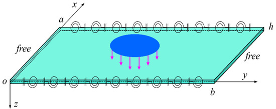
Figure 1.
Schematic diagram of bending for an orthotropic rectangular thin plates under external load.
The boundary constraint formulation for an anisotropic thin plate that is elastically rotationally limited in the x-direction but free in the y-direction is as follows:
where Rx0 and Rxa are the stiffnesses of the rotating springs on the x = 0 and a sides, respectively, which may be stated using the elasticity coefficient rx0, rxa. The formula is as follows:
The double sine–cosine series is chosen as the trial function of the plate deflection W(x,y) based on the plate’s boundary conditions as follows:
where , , and are the displacement function’s Fourier coefficients, where .
The expansion W(x,y) of the first four orders of the derivatives of the deflection is obtained using Stoke’s transformation approach as follows:
where . The formulas for the remaining unknown coefficients are as follows:
Introducing Equations (5)–(7) into the control equations yields the following equations:
where qmn is the load Fourier coefficient, and it is expressed as .
The following relationship may be calculated with zero displacement at the elastic rotation constraint border and zero equivalent shear at the free edge:
It is not difficult to determine that -Dxcn and -Dxdn are the Fourier coefficients of the bending moment of the thin plate on the boundary x = 0, a, at which point the bending moment on the boundary may be determined directly using the Fourier series property. The expressions are as follows:
The following equation is obtained by combining Equations (10) and (12) and simplifying Equation (9):
As a result, an equation for the deflection W(x,y)’s Fourier coefficients Wmn may be constructed as follows:
Let , , . The displacement function’s resultant Fourier coefficient Wmn might be simplified to:
The displacement function’s Fourier coefficient Wmn is introduced into Equation (4), from which the formula for the analytical solution of the anisotropic thin-plate bending issue may be generated as follows:
The displacement function in the preceding derivation satisfies the constraints of zero deflection on the elastic side and zero equivalent shear force on the free side, and it also has to meet the conditions related to the bending moment on both the elastic and free sides. As a consequence, the unknown coefficients cn, dn, em, and fm can be calculated in the displacement function W(x,y). The analytical solutions for the formulas regarding the angle of rotation on the elastic side, the bending moment, and the bending moment on the free side are found using Equations (5), (6), and (13). Additionally, to satisfy the corresponding conditions, the following system of chi-square linear algebraic equations is obtained:
When n = 0, 1, …
When m = 1, 2, …
where .
Equations (18)–(21) are infinite linear algebraic equation systems with regard to cn, dn, em, and fm. The solutions are definite since the number of unknown coefficients to be found is equal to the number of equations in the system. m, n only need to take a limited number of terms to provide findings that meet engineering accuracy criteria. In this study, m was considered the Mth term, n was considered the Nth term, and the number of all terms considered was t; that is M = t, N = t − 1.
Using the commercially available numerical computer software Mathematica 11.3, one may determine the values of cn, dn, em, and fm by programming the preceding system of chi-square linear algebraic equations. An analytical solution for the deflection in the bending of anisotropic thin plates may be found by substituting the obtained coefficients into Equation (17). By differentiating the resulting analytical solution term by term, an analytical solution for the internal forces at every place of the plate may be derived. The bending moment Mx on the elastic turning edge, for example, may be calculated immediately using Equation (13), The following equation may be used to compute the bending moments Mx and My at various points on the plate:
3. Calculation Examples
In addition to delivering precise findings for displacements and inclusions in the bending of RFRF anisotropic rectangular thin plates, the implementation of a two-dimensional enhanced Fourier series solution eliminates the need for an extra derivation step. The analytical solution based on the results obtained in this paper can also provide accurate results for the bending problems of isotropic/anisotropic thin plates with SFSF, CFSF, and CFCF isotropy by adjusting the selected spring parameter r (r ranges from 0 to 1; in this section, when the spring parameter r = 0.000001, it represents the boundary as a simply supported edge, and r = 0.999999 represents the boundary as a clamped edge). It is worth noting that when the plate is isotropic, H = Dx = Dy = D, Dxy = (1 − µ)D/2, µx = µy = µ = 0.3. The values of the b/a aspect ratio were 0.5, 1.0, 1.5, 2.0, 2.5, and 3.0, respectively. An isotropic/anisotropic thin plate with the aforementioned boundary constraints was used as an example to test the validity of this solution and the accuracy of the ensuing analytical solution. The dimensionless results of the deflection and internal forces of thin plates under various types of external loads were estimated in this work. The present method was calculated in Wolfram Mathematica 10.0 software, and the FEM results were obtained on a workstation equipped with an Intel Xeon processor E5-2697 4 (x2) (45M Cache, 2.30 GHz). Finite element calculations were performed using the finite elements derived from ABAQUS software for the S4R shell element.
3.1. An Example of a Thin Plate with Two Simply Supported Edges and Two Free Edges
For the SFSF isotropic plate (x = 0, a x = simply supported edge; y = 0, b free edge), rx0 = rxa = 0.000001. Thin plates were subjected to uniform loads (q). Table 1 shows the computed deflection values and bending moments of the plates at various positions. The elastic properties of the SFSF anisotropic thin plate were Dy = 2Dx, D1 = 0.15Dx, Dxy = 0.425Dx, and H = Dx. The load type was a concentrated load at (0.25a, 0.5b) of the slab P. The values of the plate’s deflection and bending moment at various points were determined, and the results are given in Table 2. Figure 2 illustrates a schematic diagram of the dimensionless change in the deflection of the SFSF isotropic rectangular thin plate under uniform load.

Table 1.
Results for nondimensional deflection and bending moments at different positions of an isotropic SFSF rectangular thin plate subjected to uniformly distributed load q.
Table 2.
Results for nondimensional deflection and bending moments at different positions of an orthotropic SFSF rectangular thin plate subjected to concentrated load P.
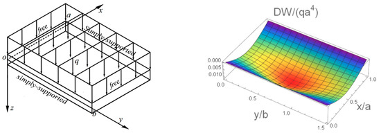
Figure 2.
A schematic diagram for the three-dimensional deflection of an isotropic SFSF rectangular thin plate under uniformly distributed load q.
The dimensionless deflection values and bending moments of the SFSF isotropic/anisotropic thin plates derived using this paper’s solution approach are accurate to five significant digits, as shown in Table 1 and Table 2. The convergence of the ensuing analytical solution is consistent since the trial function selected for this section is a two-dimensional sine–cosine series. To ensure the precision of the resultant analytical solution, t was set to 500 terms in the computation method used in this study. Also, except for the bending moments at the simply supported edge, the deflection values and bending moments at other locations of the thin plate are in good agreement with the FEM results. The bending moment at the simply supported edge is theoretically zero, and the results based on this solution are zero, but the FEM results are nonzero and have a large error. This demonstrates the significance of developing precise analytical solutions to structural mechanics issues involving pavement thin slabs. The results produced using this solution almost fully meet the criterion that the bending moment at the simply supported edge should be zero, as shown in Figure 2, demonstrating the correctness and efficacy of the solution method.
3.2. Arithmetic Examples of Thin Plates with One Side Using Clamped Support, One Side Using Simple Support, and Two Sides Free
For the CFSF isotropic thin plate (x = 0 cantilever; x = a simple support; y = 0, b free edge), rx0 = 0.999999, rxa = 0.000001. The thin plate was exposed to uniform load q, and the deflection and internal forces achieved are reported in Table 3. The elastic characteristics of the CFSF anisotropic thin plate were Dy = 2Dx, D1 = 0.15Dx, Dxy = 0.425Dx, and H = Dx. The plate was exposed to a concentrated load at (0.25a,0.5b), and the deflection and bending moment values obtained are shown in Table 4. The deflection diagram of the CFSF anisotropic square thin plate under concentrated load is also illustrated in Figure 3.
Table 3.
Results for nondimensional deflection and bending moments at different positions of an isotropic CFSF rectangular thin plate subjected to uniformly distributed load q.
Table 4.
Results for nondimensional deflection and bending moments at different positions of an orthotropic CFSF rectangular thin plate subjected to concentrated load P.
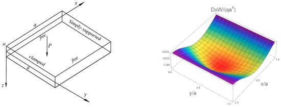
Figure 3.
A schematic diagram for the three-dimensional deflection of an orthotropic CFSF square thin plate under concentrate load P.
As can be seen from Table 3, Table 4, Table 5 and Table 6, the results obtained from the solution method in this paper regarding the CFSF and CFCF isotropic/anisotropic thin plates are in good agreement with the FEM results. Figure 3 and Figure 4 additionally demonstrate that the outcomes of this article properly fulfill the boundary constraints. The fact that the bending force is zero on the simply supported edge, for example, and the angle of rotation is zero on the clamped edge, further demonstrates the solution’s correctness.
Table 5.
Results for nondimensional deflection and bending moments at different positions of an isotropic CFCF rectangular thin plate subjected to locally uniformly distributed load q.
Table 6.
Results for nondimensional deflection and bending moments at different positions of an orthotropic CFCF rectangular thin plate subjected to uniformly distributed load q.
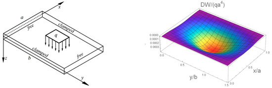
Figure 4.
A schematic diagram for the three-dimensional deflection of an isotropic CFCF rectangular thin plate with locally uniformly distributed load q.
3.3. An Arithmetic Example of Thin Plates with Two Edges Using Clamped Supports and Two Edges Free
For the CFCF isotropic thin plate (x = 0, a clamped support edge; y = 0, b free edge), rx0 = rxa = 0.999999. The central thin plate was subjected to a local (load range: x direction 0.4 a 0.6 a, y direction 0.4 b 0.6 b) uniform load q to determine the deflection value of the thin plate at different locations and the value of the bending moment. The results are presented in Table 5.
The elastic parameters of the CFCF anisotropic thin plate were Dy = 3.9Dx, B, and C. A consistent load D was applied to the thin plate. Table 6 shows the obtained deflection and bending moment values. In addition, Figure 4 shows a schematic of the dimensionless change in the deflection of the CFCF isotropic rectangular thin plate under a locally uniform load.
3.4. An Arithmetic Example of Thin Plates with Two Elastically Rotating Edges and Two Free Edges
For RFRF isotropic thin plates using varied spring values ((x = 0, a) elastically limited edge; y = 0, b free edge), the center of the plate was exposed to a concentrated load P when rx0 = rxa = r varied between 0 and 1. Table 7 shows the computed and listed deflection values of the plates at various locations. The elastic parameters of the RFRF anisotropic thin plate were Dy = 3.9Dx, Dxy = 0.85Dx and µy = 0.3, and the value of rx0 = rxa = r changed from 0.5 to 1. q is the uniform load applied to the plate. Table 8 shows the deflection values and bending moments of a thin plate with various spring settings.
Table 7.
Results for the nondimensional deflection, , of an isotropic RFRF rectangular thin plate under a concentrated load P.
Table 8.
Results for the nondimensional deflection and bending moment of an orthotropic RFRF rectangular thin plate subjected to uniformly distributed load q.
4. Conclusions
Using the two-dimensional sine–cosine series as the trial function of the displacement function, we proposed an improved Fourier series solution method with the Stokes transform technique to obtain the expressions of the higher-order partial differential terms of the displacement function, which were inputted into the control equations to obtain the expressions of the Fourier coefficients of the displacement function as the positive transform. Then, the expressions for the analytical solution of the problem containing the unknown coefficients were formulated, and a series of linear algebraic equations were obtained by satisfying the corresponding boundary conditions, and the values of the corresponding coefficients were determined through calculation. This finally yielded the analytical solution for the bending problem of anisotropic RFRF rectangular thin plates. In addition, the values of the deflection and bending moment under different loads (concentrated, uniform, and localized) were determined. No additional derivation procedure is required, as the spring parameters defined in the paper can be adjusted to provide accurate results for the bending problems of SFSF, CFSF, and CFCF thin plates. Finally, a comparison of the computational examples shows that the results obtained based on this solution method fully satisfy the boundary conditions and are in good agreement with the exact solution results and finite element results in the literature, which verifies the correctness of the derived formulas. The results can also be used as a reference for verifying the numerical/approximate solution of rectangular thin-plate bending problems with different elastic constants.
Author Contributions
Conceptualization, Y.M. (Yanyu Meng) and B.L. (Bing Leng); Methodology, B.L.; Software, H.X. (Haidong Xu) and K.W. (Kaihang Wang); Validation, G.Y. (Guangyao Yang) and H.X.; Formal analysis, Y.Y. (Yan Yan); Investigation, Y.Y. (Yan Yan) and H.X.; Data curation, K.W. (Kaihang Wang); Writing—review and editing, B.L. (Bing Leng) and Y.M.; Visualization, H.X. and G.Y.; Supervision, Y.M.; Project administration, B.L.; Funding acquisition, Y.M. All authors have read and agreed to the published version of the manuscript.
Funding
The authors gratefully acknowledge the support they received from the Project of the Jilin Provincial Department of Education (JJKH20230068KJ, 2015238), the Jilin Provincial Science and Technology Award (2020J3G056), the Jilin Science and Technology Bureau Project (201614001), and the Beihua University Doctoral Research Initiation Fund (202301).
Data Availability Statement
The data presented in this study are available within this article.
Conflicts of Interest
Author Yan Yan was employed by the company Jilin Mengxi Engineering Management Co. The remaining authors declare that the research was conducted in the absence of any commercial or financial relationships that could be construed as a potential conflict of interest.
References
- Zienkiewicz, O.C.; Cheung, Y.K. The finite element method for analysis of elastic isotropic and orthotropic slabs. Ice Proc. 1964, 28, 471–488. [Google Scholar] [CrossRef]
- Cheungb, Y.K. Finite Strip Method in Structural Analysis; Pergamon Press: London, UK, 1976. [Google Scholar]
- Chakravorty, A.K.; Ghosh, A. Finite difference solution for circular plates on elastic foundations. Int. J. Numer. Methods Eng. 2010, 9, 73–84. [Google Scholar] [CrossRef]
- Civalek, Ö.; Dastjerdi, S.; Akgöz, B. Buckling and free vibrations of CNT-reinforced cross-ply laminated composite plates. Mech. Based Des. Struct. Mach. 2022, 50, 1914–1931. [Google Scholar] [CrossRef]
- Civalek, O.; Ülker, M. Harmonic differential quadrature (HDQ) for axisymmetric bending analysis of thin isotropic circular plates. Struct. Eng. Mech. 2004, 17, 1–14. [Google Scholar] [CrossRef]
- Tian, B.; Li, R.; Zhong, Y. Integral transform solutions to the bending problems of moderately thick rectangular plates with all edges free resting on elastic foundations. Appl. Math. Model. 2015, 39, 128–136. [Google Scholar] [CrossRef]
- Thai, H.T.; Choi, D.H. Analytical solutions of refined plate theory for bending, buckling and vibration analyses of thick plates. Appl. Math. Model. 2013, 37, 8310–8323. [Google Scholar] [CrossRef]
- Cheung, Y.K.; Zhou, D. Vibrations of moderately thick rectangular plates in terms of a set of static timoshenko beam functions. Comput. Struct. 2000, 78, 757–768. [Google Scholar] [CrossRef]
- Yuan, Y.; Xing, Y. A separation-of-variable method for the wrinkling problems of orthotropic rectangular stretched sheets. Compos. Struct. 2022, 300, 116104. [Google Scholar] [CrossRef]
- Zhang, S.; Xu, L. Analytical solutions for flexure of rectangular orthotropic plates with opposite rotationally restrained and free edges. Arch. Civ. Mech. Eng. 2018, 18, 965–972. [Google Scholar] [CrossRef]
- Li, R.; Zhong, Y. On a new symplectic geometry method for exact bending solutions of orthotropic rectangular plates with two opposite sides clamped. Acta Mech. 2011, 216, 333–343. [Google Scholar] [CrossRef]
- Gurses, M.; Akgoz, B.; Civalek, Ö. Mathematical modeling of vibration problem of nano-sized annular sector plates using the nonlocal continuum theory via eight-node discrete singular convolution transformation. Appl. Math. Comput. 2012, 219, 3226–3240. [Google Scholar] [CrossRef]
- Ebrahimi, F.; Barati, M.R.; Civalek, Ö. Application of chebyshev–ritz method for static stability and vibration analysis of nonlocal microstructure-dependent nanostructures. Eng. Comput. 2019, 36, 953–964. [Google Scholar] [CrossRef]
- Akgz, B.; Civalek, M. Buckling analysis of functionally graded microbeams based on the strain gradient theory. Acta Mech. 2013, 224, 2185–2201. [Google Scholar] [CrossRef]
- Akgz, B.; Civalek, M. A microstructure-dependent sinusoidal plate model based on the strain gradient elasticity theory. Acta Mech. 2015, 226, 2277–2294. [Google Scholar] [CrossRef]
- Akgoz, B.; Civalek, Ö. C4 bending analysis of embedded carbon nanotubes resting on an elastic foundation using strain gradient theory. Acta Astronaut. 2016, 119, 1–12. [Google Scholar] [CrossRef]
- Zozulya, V.V. Higher order couple stress theory of plates and shells. ZAMM-J. Appl. Math. Mech. 2018, 98, 1834–1863. [Google Scholar] [CrossRef]
- Lisboa TD, V.; Marczak, R.J. Application of Adomian-type method to solve rectangular laminated thick plates in bending. ZAMM-J. Appl. Math. Mech./Z. Angew. Math. Mech. 2019, 99, e201800151. [Google Scholar] [CrossRef]
- Wu, M.; Fan, S.; Zhao, Z.; Liu, M.; Hu, L.; Yu, T. Experimental study on the hysteretic behavior of aluminum alloy gusset joint with rectangular hollow sections. Thin-Walled Struct. 2024, 196, 111500. [Google Scholar] [CrossRef]
- Ye, J.; Zhang, J.; Yu, J.; Yu, J.; Yu, K. Flexural behaviors of 3D printed lightweight engineered cementitious composites (ECC) slab with hollow sections. Eng. Struct. 2024, 299, 117113. [Google Scholar] [CrossRef]
- Zhang, X.M.; Wang, Y.C.; Su, M.N. Experimental, numerical and analytical study to develop a design method for bending and shear resistances of 3D printed beetle elytron inspired sandwich plate (beetle elytron plate). Thin-Walled Struct. 2023, 183, 110371. [Google Scholar] [CrossRef]
- Liu, D.; Ma, K.; Lu, Y.; Xiao, J.; Kuang, K. Bending theory of vierendeel sandwich plate based on variational method. Compos. Struct. 2023, 306, 116570. [Google Scholar] [CrossRef]
- Gorman, D.J.; Garibaldi, L. Accurate analytical type solutions for free vibration frequencies and mode shapes of multi-span bridge decks: The span-by-span approach. J. Sound Vib. 2006, 290, 321–336. [Google Scholar] [CrossRef]
- Hurlebaus, S. Calculation of eigenfrequencies for rectangular free orthotropic plates—An overview. ZAMM—J. Appl. Math. Mech./Z. Angew. Math. Mech. 2007, 87, 762–772. [Google Scholar] [CrossRef]
- Jiang, H.J.; Dai, H.L.; Li, S.Z. Refined plate theory for bending analysis of a hsla steel plate under 3d temperature field. Appl. Math. Comput. 2015, 250, 497–513. [Google Scholar] [CrossRef]
- Ruocco, E.; Reddy, J.N. A closed-form solution for buckling analysis of orthotropic reddy plates and prismatic plate structures. Composites 2019, 169, 258–273. [Google Scholar] [CrossRef]
- Arefi, M.; Firouzeh, S.; Bidgoli, M.R.; Civalek, M. Analysis of porous micro-plates reinforced with fg-gnps based on reddy plate theory. Compos. Struct. 2020, 247, 112391. [Google Scholar] [CrossRef]
- Schreiber, P.; Mittelstedt, C.; Beerhorst, M. Buckling of shear-deformable orthotropic laminated plates with elastic restraints. Thin-Walled Struct. 2020, 157, 107071. [Google Scholar] [CrossRef]
- Zhang, F. Thin Elastic Plate, 2nd ed.; The Science Press: Beijing, China, 1984. (In Chinese) [Google Scholar]
Disclaimer/Publisher’s Note: The statements, opinions and data contained in all publications are solely those of the individual author(s) and contributor(s) and not of MDPI and/or the editor(s). MDPI and/or the editor(s) disclaim responsibility for any injury to people or property resulting from any ideas, methods, instructions or products referred to in the content. |
© 2024 by the authors. Licensee MDPI, Basel, Switzerland. This article is an open access article distributed under the terms and conditions of the Creative Commons Attribution (CC BY) license (https://creativecommons.org/licenses/by/4.0/).