Article

Enhancing Flexural Resistance in Pre-Damaged RC Beams with Near-Surface Mounted GFRP Bar and Bolt Anchoring System

1
Civil and Environmental Engineering, University of Missouri, Columbia, MO 65211, USA
2
Materials Engineering, Zagazig University, Zagazig 44519, Egypt
3
Civil Engineering Department, Higher Technological Institute (HTI), 10th of Ramadan City 44629, Egypt
*
Author to whom correspondence should be addressed.
Buildings 2024, 14(3), 723; https://doi.org/10.3390/buildings14030723
Submission received: 9 February 2024 / Revised: 5 March 2024 / Accepted: 5 March 2024 / Published: 7 March 2024
(This article belongs to the Section Building Structures)

Abstract

:
The objective of this research was to explore the mechanical properties and failure mechanisms of reinforced concrete beams (RC beams) strengthened with near-surface mounted (NSM) glass fiber-reinforced polymer (GFRP) bars. This study focused on evaluating the effect of various factors on the load-deflection response and failure patterns of RC beams, including pre-existing damage, end anchorage, bar length, bar number, and the condition of concrete cover. The tested RC beams were divided into three groups. The first group included undamaged and damaged control beams. The second group involved the strengthening of beams after inducing damage, with variations in bar length, number, and cross-sectional area. This group also included beams strengthened by GFRP bars with and without anchors. In the third group, the effects of different cover materials, cover bonding techniques, and anchor bolts on the strengthening bars were examined. The results of the experiment indicated a notable decrease in both cracking and maximum load capacity for beams that were pre-damaged. The inclusion of anchor bolts appeared to have a noticeable effect, enhancing the load-carrying capacity and reducing mid-span deflection. Opting for two bars proved to be more effective than using three bars, leading to a higher maximum load and improved ductility. Moreover, prioritizing the bonding of the concrete cover at the end of the bars was found to be more important than bonding in the area of maximum moment.

1. Introduction

Presently, there is an increasing demand to enhance global infrastructure. There are various approaches to fortifying reinforced concrete structures, with externally bonded reinforcement (EBR) [1,2] and the near-surface mounted (NSM) method emerging as the most commonly employed. In numerous countries, the NSM method has been applied for the repair and strengthening of structural elements, proving to be a promising technique for augmenting the load-bearing capacity of reinforced concrete (RC) beams. The implementation involves two key stages: initially, grooves are incised into the concrete cover of RC elements, followed by the insertion of Fiber Reinforced Polymer (FRP) rods into these grooves, securely bonded with epoxy resin. The NSM method holds great promise for the rehabilitation of RC members, with several researchers highlighting its advantages over conventional methods [3,4,5,6,7]. Several laboratory studies have been conducted to analyze the bonding characteristics between NSM FRP bars and concrete. These investigations have also explored the impact of different factors, such as the FRP anchorage system, NSM FRP length, epoxy type, groove dimensions, composition of rebars, and the compressive strength of concrete [8,9,10,11,12,13]. Considerable scholarly efforts have focused on improving the bonding effectiveness to enhance the flexural and shear capabilities of reinforced concrete beams undergoing strengthening procedures. The NSM strengthening technique presents a viable alternative to the EBR technique. In NSM, the surrounding concrete acts as a protective layer for NSM bars or strips, shielding them from environmental, thermal, and mechanical damage. This, in turn, helps to delay or prevent premature failure. The initial experiments on this technique were conducted by Nguyen et al. [14], who utilized CFRP strips placed in grooves cut into concrete specimens. Numerous other experimental studies have investigated the flexural properties of RC beams strengthened with NSM bars or strips composed of FRP materials [15,16,17,18]. While FRP reinforcement offers benefits, such as lightweight design, high corrosion resistance, and potential durability, it comes with a significant cost. Moreover, FRP reinforcements exhibit limited ductility. Previous studies have indicated that the effectiveness of NSM FRP strengthening is restricted in reaching its maximum tensile strength due to premature failure caused by FRP debonding or modes of concrete splitting failure [19,20,21,22]. Recent studies have explored the effects of mechanical properties, the cross-sectional area of FRP bars, and the type of adhesive epoxy on the flexural strength of beams. This research focuses on how these factors influence the load-bearing capacity of beams when subjected to the NSM technique. The findings emphasize the substantial impact of the stiffness of FRP bars on the maximum load of beams reinforced through NSM FRP. The length of the GFRP bars used for NSM reinforcement plays a crucial role in determining the effectiveness of the reinforcement mechanism. Longer bars provide greater bonding lengths and increase the adhesive surface area, resulting in a higher maximum load. However, it is essential to carefully choose the bonding length to fully utilize the potential of GFRP bars while avoiding premature bond failure. The quantity of GFRP bars used for NSM strengthening also plays a significant role in overall performance. The addition of more bars can enhance the structural capacity to withstand bending and shear forces by distributing the applied loads more evenly. Nevertheless, an excessive number of bars may lead to congestion and insufficient cover, potentially compromising the bond strength and overall durability of the system [23,24].
When enhancing the strength of concrete with GFRP bars, it is crucial to take into account the potential occurrence of debonding. This phenomenon arises when the FRP bars become detached from the concrete, often due to factors such as insufficient bond length, inadequate surface preparation, or excessive loads. The probability of debonding is influenced by both the quantity and length of GFRP bars employed, impacting not only the likelihood of occurrence but also the overall cost and installation convenience. The utilization of longer bars or a greater number of bars may result in increased material expenses and heightened complexity during the installation process. However, the effects of bar length and quantity on NSM strengthening with GFRP bars can vary based on specific project requirements, structural configurations, and the properties of the GFRP material utilized. As a result, conducting thorough research, including experimental testing and analysis, becomes essential to optimizing the design of each individual project [25,26,27]. Bar end anchors are crucial for a robust connection between GFRP bars and adjacent concrete in NSM strengthening. Proper anchorage prevents debonding and slippage, ensuring effective load transfer. Success depends on anchor type and design, with researchers exploring various techniques. Adequate concrete cover is vital to protect GFRP reinforcement from external factors and to preserve the bond with the concrete.
The residual flexural behavior of RC beams strengthened with Fiber Reinforced Cementitious Matrix (FRCM) under varying temperatures and the bond behavior of FRCM composites on concrete substrates have been investigated [28]. Testing revealed that strengthened beams maintained a load-bearing capacity up to 200 °C but collapsed at 300 °C with a 12% decrease in load values. A proposed model estimated residual debonding strain post-exposure, showing that strengthened beams had 13–23% higher load-bearing capacity, highlighting FRCM’s effectiveness in enhancing structural resilience. The bond behavior investigation has focused on fiber layers, loading rate effects, and peak load relationships, with observations such as a doubling of peak load with two layers of PBO fiber mesh. Further exploration is needed on loading rate effects and the number of fiber layers, with free end slips providing additional insights into the bond mechanism. Careful consideration of friction effects is crucial in peak load interpretation [29].
To gain insights into the effectiveness of bar end anchors and the optimal concrete cover thickness in NSM techniques for strengthening concrete structures with GFRP bars requires analyzing existing research. The term “pre-damaged concrete” refers to concrete that has suffered damage before undergoing NSM reinforcement. When using GFRP bars to reinforce pre-damaged concrete, factors such as the ability to form a strong bond and the impact of pre-existing cracks on bonding characteristics must be considered. The NSM strengthening process may lead to the propagation of existing cracks, posing a risk to long-term effectiveness. Additionally, altered load transfer mechanisms during NSM can affect the overall structural behavior of pre-damaged concrete, especially in cases of severe damage where NSM may not be suitable.
This paper investigated the flexural behavior and failure modes of reinforced concrete (RC) beams reinforced with Near-Surface Mounted (NSM) Glass Fiber Reinforced Polymer (GFRP) bars. Experimental analyses were methodically conducted to examine the multifaceted influence of several critical factors, incorporation pre-existing damage, end-anchorage configurations, varying bar lengths, the number of bars utilized, conditions of concrete cover, and the type of concrete cover material employed. Moreover, to provide a deeper understanding and enhance the robustness of the investigation, a non-linear finite element (FE) model was intricately developed. This model serves the purpose of validating the numerical findings against the extensive experimental results obtained throughout this comprehensive study. Through this combined approach of experimental analysis and numerical modeling, a thorough understanding of the flexural behavior and failure mechanisms in RC beams reinforced with NSM GFRP bars is achieved, thereby contributing significantly to the advancement of structural engineering knowledge and practice.

2. Experimental Work

2.1. Experimental Matrix

A total of seventeen RC beams were subjected to testing under four-point bending loading and categorized into three groups based on the studied variable parameters. The initial group comprised two reference RC beams: the first, CB1, an undamaged reference beam, and the second, CB2d, a damaged reference beam. Both beams in this group were tested without any strengthening. The second group comprised 10 RC beams reinforced using GFRP bars, with variations in length, number, area, and anchor condition (with or without anchor). The third group included five RC beams, all possessing the same number of bars. The GFRP bar length in this group equaled 0.5 times the effective length (Leff), which was the length between the two supports. Despite uniform bar parameters, the beams in this group differed in cover material, cover bonding, and anchoring system for the strengthening bars. The cover thickness for all beams was consistent at 30 mm. The configuration of the tested beams is summarized in Table 1.

2.2. Material Properties

In this research, we employed local siliceous sand with a specific gravity of 2.65 and a fineness modulus of 3.0 as the fine aggregate. The coarse aggregate selected was dolomite, with a nominal maximum size of 10 and 20 mm, a specific gravity of 2.68, and a water absorption rate of 0.90%. Additionally, we utilized Type I Ordinary Portland Cement grade 42.5 N from Suez Cement. The water-to-cement ratio employed was 0.48. Details of the concrete mix proportions are provided in Table 2.
The concrete characteristics were determined through testing cubes measuring (150 × 150 × 150 mm) for compressive strength according to BS EN 12390-12393:2009 [30], cylinders measuring (150 × 300 mm) for splitting tensile strength according to BS EN 12390-12396 [31], and prisms measuring (100 × 100 × 500 mm) for flexural strength according to BS EN 12390–5:2009 [32]. The obtained average values for compressive strength, splitting tensile strength, and flexural strength were 30.8 MPa, 2.63 MPa, and 5.49 MPa, respectively.
The steel reinforcement used had a yield strength of 448 MPa and a tensile strength of 594 MPa.
Two different diameters of GFRP bars (10 and 12 mm) from Fiber Reinforcement Industries Co. were used for NSM reinforcement (registered) were employed. The GFRP bars exhibited a tensile strength of 1020 MPa, and their modulus of elasticity was 38.6 GPa. The epoxy resin chosen for bonding the GFRP bars with concrete was MASTER BRACE SAT 4500 from BASF. This resin consisted of two components, A and B, which were mixed to achieve a blended weight of 0.984 gm/cm3. The epoxy properties, as specified by the manufacturer, are detailed in Table 3.

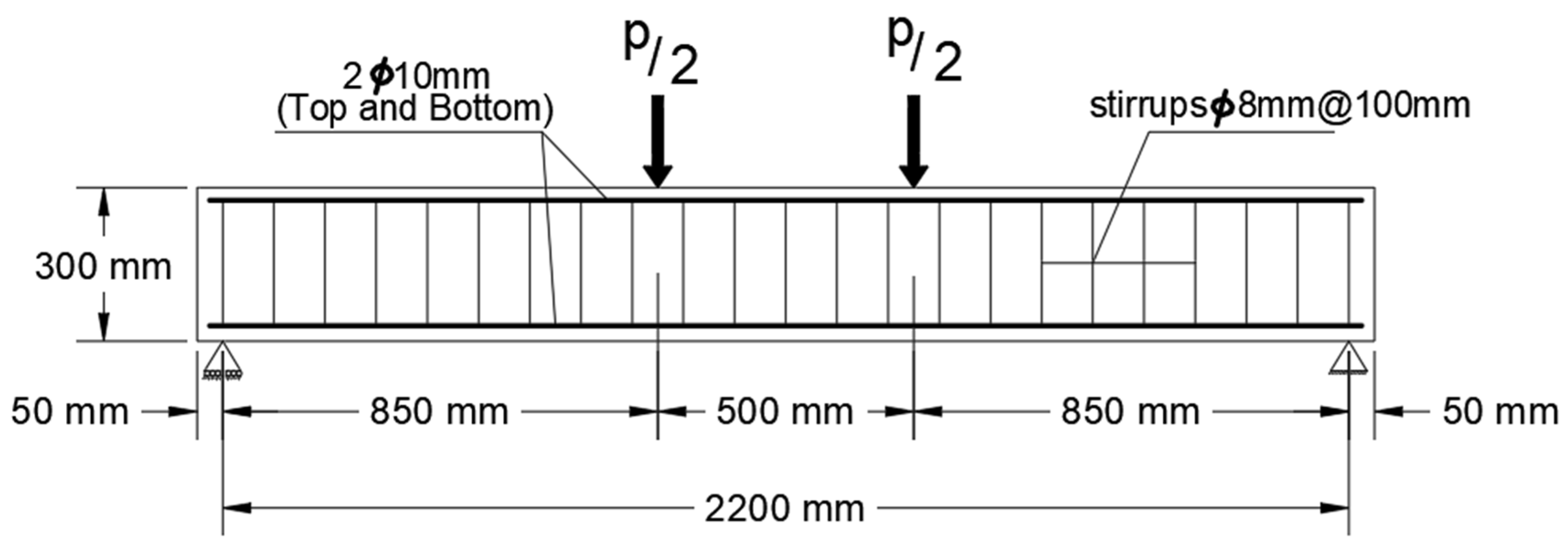
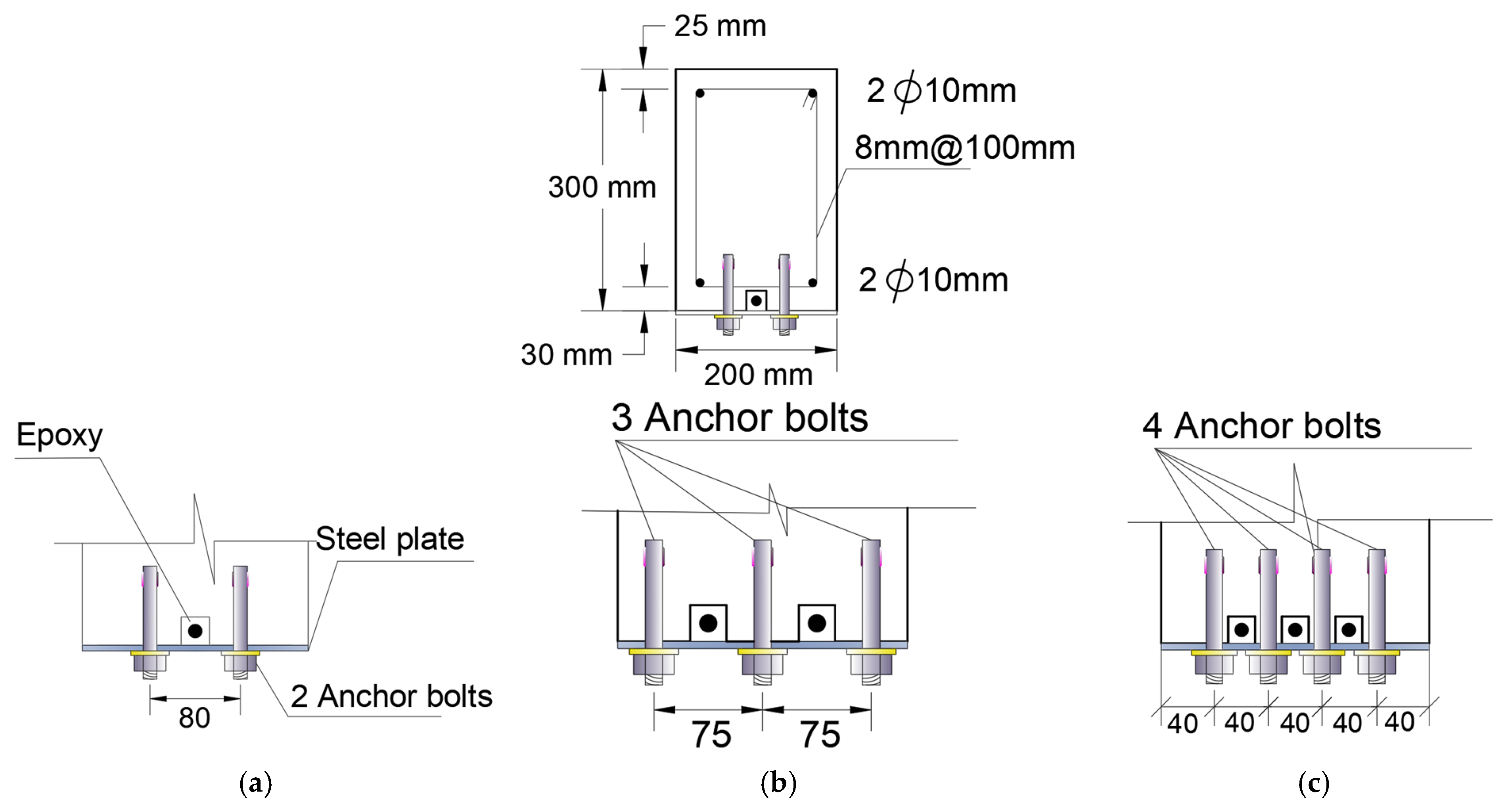
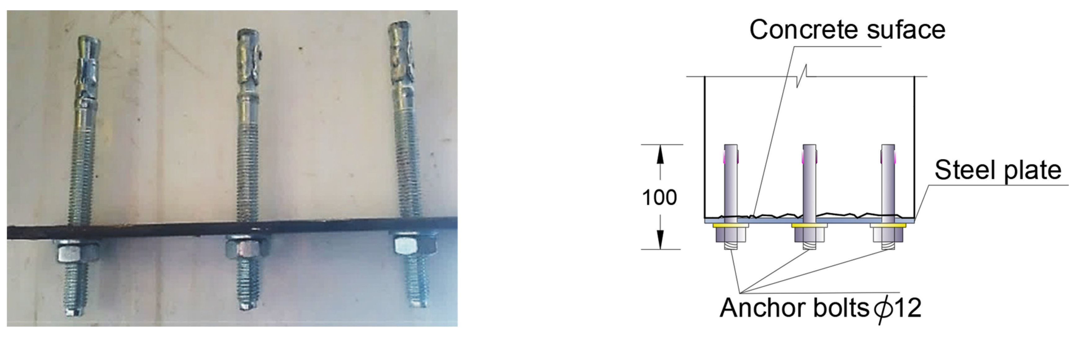
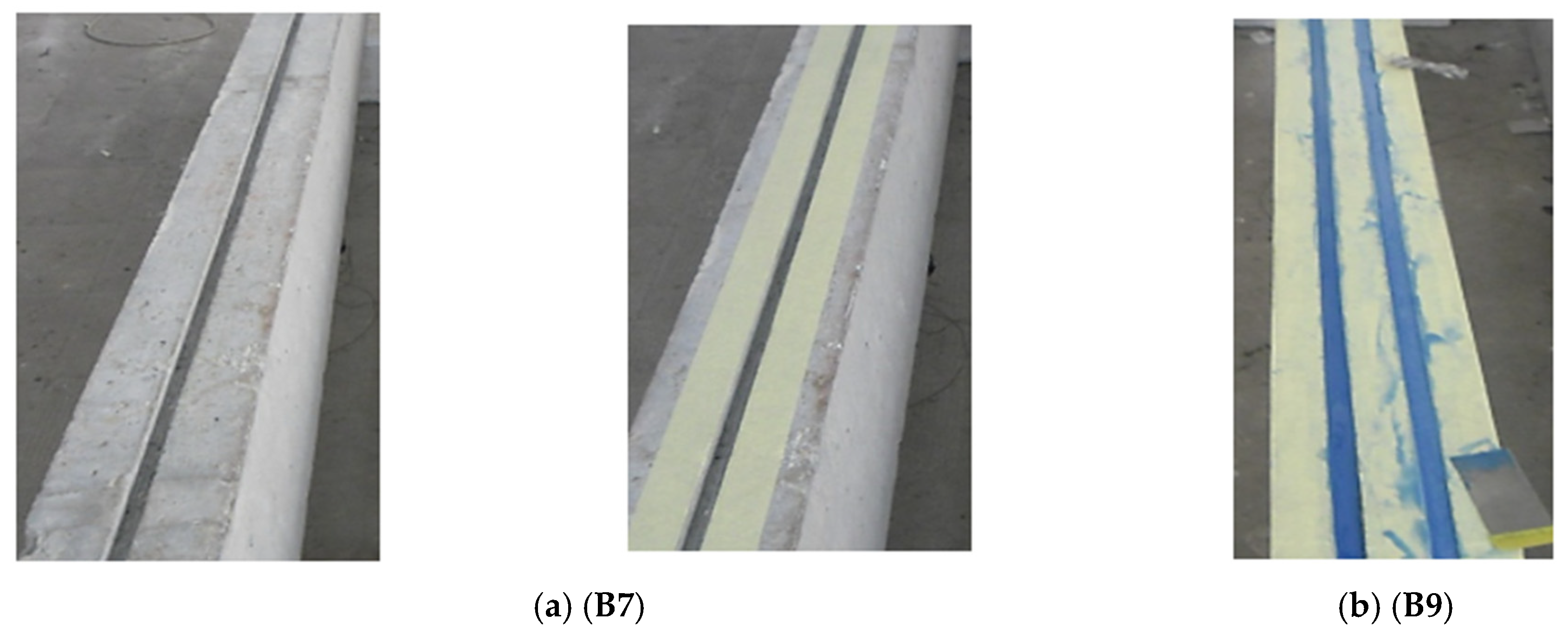
2.3. Specimen Geometry and Preparation
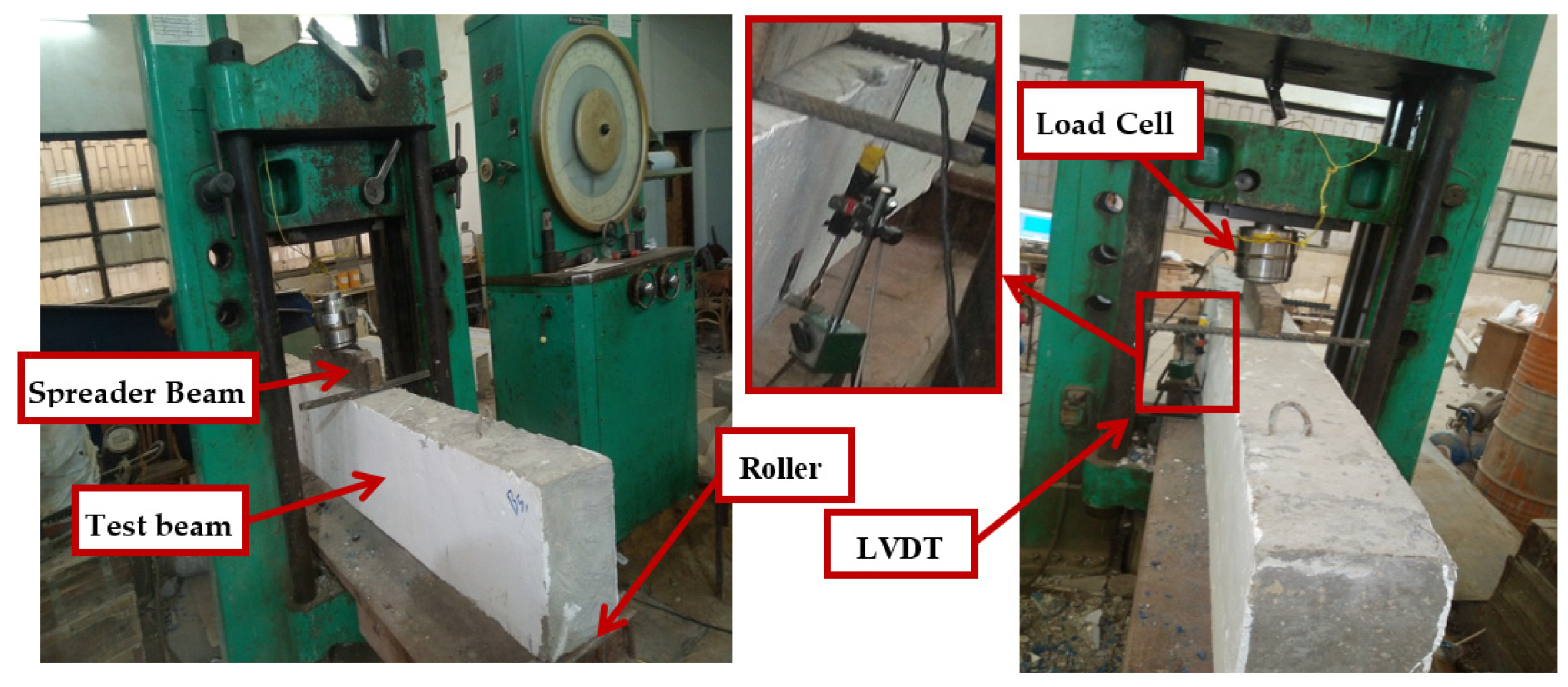
The beams underwent the mixing, casting, and compaction processes at a temperature of 23 °C. A rotary-style mixing apparatus was utilized to formulate the concrete mixes. These mixes were then arranged into three layers, followed by the application of vibration and compaction using a specialized tool. The top layer was meticulously leveled to achieve a smooth surface texture. In the creation of beams, a consistent concrete mixture was used to cast cubes, cylinders, and prisms. To ensure proper curing, the concrete cubes, cylinders, and prisms were submerged in a water reservoir for 28 days. Subsequently, they were transitioned to an open-air environment until the scheduled testing date. The evaluation of the concrete’s hardened properties was based on the analysis of these test specimens. Compressive strength was determined by testing three concrete cubes, resulting in an average compressive strength of 30.8 MPa. The tensile strength was determined through the indirect tensile test on three concrete cylinders, yielding an average splitting tensile strength of 2.63 MPa. The flexural strength of concrete was assessed by testing three concrete prisms under 3-point bending, with an average flexural strength of 5.49 MPa.
The RC beams were configured according to the guidelines of ACI 316 (2011) [33] for under-reinforced beams. These beams had a cross-sectional dimension of (200 × 300) mm, a total length of 2300 mm, and an effective span (Leff) of 2200 mm, showing the length between the two supports. The steel reinforcement setup included 2 Φ 10 mm bars on both the tension and compression sides as longitudinal reinforcements. Additionally, 8 mm diameter steel stirrups were spaced at 100 mm center to center along the beam span, as illustrated in Figure 1. Grooves were cut into the concrete cover of the tested beams, as shown in Figure 2. In the second group, multiple load cycles were applied to create a cracked section, while in the third group, the concrete cover was cast after the beam casting to simulate concrete cover failure due to steel corrosion using different cover materials. After 28 days of curing, the grooves were cut in the longitudinal direction in the third group at the tension face. Once the necessary drilling was completed, anchor holes were prepared for the insertion of bolts. Steel anchor bolts with dimensions of 10 mm in diameter and 100 mm in length were used to establish the anchor plates on the GFRP bars and concrete. Anchor plates measuring 5 mm in thickness, 50 mm in width, and 200 mm in length were employed, as shown in Figure 3. Detailed anchor specifications can be seen in Figure 4.
The grooves were partially filled with epoxy, followed by the placement of the GFRP rods into these grooves. Once the rods were correctly positioned, the remaining grooves were also saturated with the adhesive substance, and the external surface was leveled and smoothed, as illustrated in Figure 5. After a period of 7 days, the anchoring plate was securely fixed to complete the procedure using bolts. To ensure a reliable grip, the grooves were partially occupied with epoxy adhesive, and the rods were meticulously positioned and securely embedded in the adhesive. Following the proper placement of rods, the remaining grooves were infused with the adhesive substance, and the exterior surface was leveled and smoothed, as shown in Figure 5. Subsequently, ample time was allowed for the beams to achieve their maximum adhesive potency, spanning over a week. The anchoring plate was then affixed and firmly secured using bolts to finalize the procedure.

2.4. Test Setup

Beam BC1 experienced static monotonic loading conditions in a four-point bending setup until it reached the point of failure. On the other hand, Beam BC2d experienced initial damage through three distinct loading cycles, each equivalent to 0.125, 0.25, and 0.5 of the failure load of Beam BC1. Subsequently, it proceeded with static loading conditions involving four loading points until it reached the failure load.
The second set of beams (Beams B3–B12) underwent cyclic loading corresponding to 0.125, 0.25, and 0.5 times the failure load of BC1 to induce damage, leading to the development of cracks in their sections resembling BC2d. Subsequently, these beams underwent four-point bending tests until complete failure, utilizing a 1000 kN capacity universal testing machine, as illustrated in Figure 6. For beams B13–B17 (third group), fresh concrete cover was applied after 28 days of curing, following the bonding conditions outlined in Table 1. Following an additional 28 days of curing for the new cover, the beams underwent monotonic static loading conditions similar to those applied to beam BC1.
Testing the beams involved the use of a robust steel spreader beam to apply the load. A load cell was positioned between the steel spreader beam and the machine, as illustrated in Figure 6. The vertical deflection of the beams at the mid-span was measured using linear variable differential transformers (LVDTs). Additionally, an electrical strain gauge with a 6-mm attachment was employed to measure the strain deformation at the main reinforcing steel and NSM-GFRP bars.

3. Results and Discussion

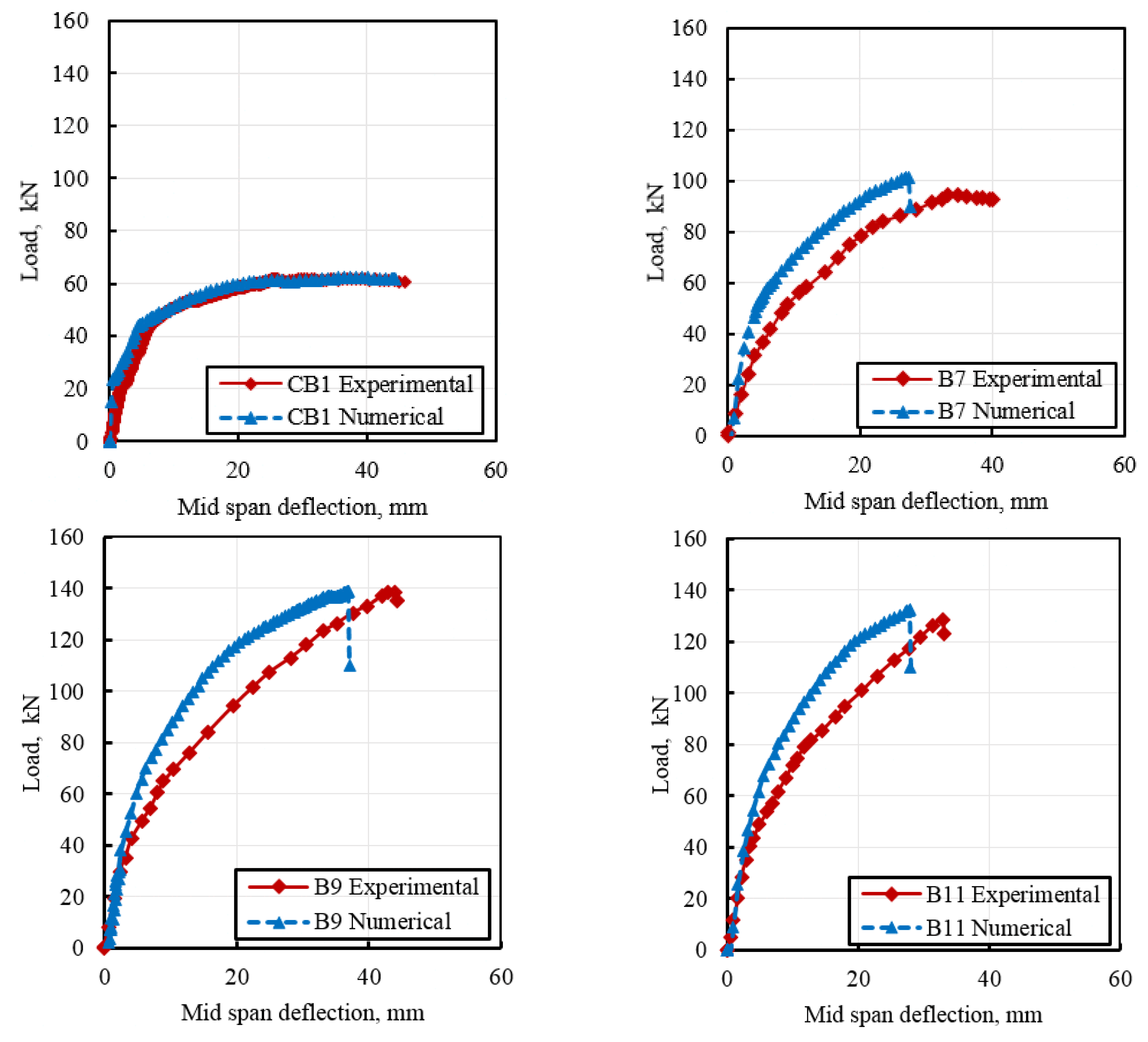
3.1. Numerical Validation

Nonlinear finite element (FE) simulation using ANSYS was conducted to validate the experimental findings of the tested RC beams. In this model, the CTP215 element was chosen to simulate the concrete, while the steel reinforcement and NSM GFRP bars were represented using the REINF264 element. Loading plates were modeled using the SOLID185 element, as depicted in Figure 7. To account for the slippage behavior of the bond between the concrete and the NSM GFRP bars, the CONTA174 element was employed, incorporating a cohesive zone model (CZM) [34].
The concrete utilized in this study exhibited notable material properties, including a compressive strength of 30.8 MPa, a tensile strength of 2.63 Mpa, an elastic modulus of 20 Gpa, and a Poisson’s ratio of 0.2. In contrast, the reinforcing steel featured a yield strength of 448 Mpa, a maximum strength of 594 Mpa, an elastic modulus of 200 Gpa, and a Poisson’s ratio of 0.3. The NSM GFRP bars, on the other hand, demonstrated impressive mechanical characteristics, with a tensile strength of 1020 Mpa, an elastic modulus of 38.6 Gpa, and a Poisson’s ratio of 0.26.
To validate the accuracy of the numerical model, a detailed comparison was made between the experimental results and the numerical simulations for RC beams CB1, B7, B9, and B11. This comparison, illustrated in Figure 8, showcased a high level of agreement between the numerical predictions and the experimental observations. Such close alignment between the two sets of results underscores the reliability and effectiveness of the numerical modeling approach employed in the study, further enhancing the credibility of the findings.

3.2. Experimental Results

The section below provides load-deflection curves and failure modes for the reference beams under flexural loading, both with and without damage, as well as for CB1 and CB2d. Figure 9 illustrates the load-deflection data, while Figure 10 and Figure 11 depict the failure modes.
As shown in Figure 9, when the load is applied, the beam exhibits elastic behavior, meaning that it undergoes deformation proportionate to the applied load. As the load intensifies, the beam reaches its yield point at approximately 50 kN and a mid-span deflection of around 7 mm, initiating plastic deformation in the steel reinforcement. The concrete remained elastic during this phase. With further load increments, the steel reinforcement surpassed its yield strength, resulting in cracks forming at the bottom of the beam, as illustrated in Figure 10. Tension cracks were localized in the region of permanent deformation. The mid-span of the beam, experiencing maximum stress, becomes the primary location for the plastic hinge. As the load continues to rise, reaching its peak at 75 kN, the concrete in the compression zone may begin to fail through crushing when the stress surpasses the ultimate strength of the concrete. This crushing is often accompanied by cracking and spalling in the compression zone, with the maximum recorded mid-span deflection reaching approximately 55 mm.
For beam CB2d, the loading initiates with a preliminary loading phase. Initially, CB2d undergoes pre-damage loading by subjecting it to loads equivalent to 0.125 (7.5 kN), 0.25 (15 kN), and 0.5 (30 kN) of the maximum load of beam CB1. Subsequently, static loading conditions are applied under four points of loading until reaching the maximum load of 62 kN with a decrease of 20.9% when compared with CB1. The pre-damage loading-unloading sequences are illustrated in Figure 9, and the corresponding load-deflection data for the pre-damage stage are presented in the same figure. The results indicate a reduction in the yielding load of beam CB2d to approximately 44 kN, accompanied by a decrease in mid-span deflection to about 5 mm. Additionally, the maximum load was determined to be around 62 kN. It is evident that the pre-damage inflicted on beam CB2d leads to a significant decrease in both cracking and maximum loads. The failure mode and crack pattern of beam CB2d are depicted in Figure 11.

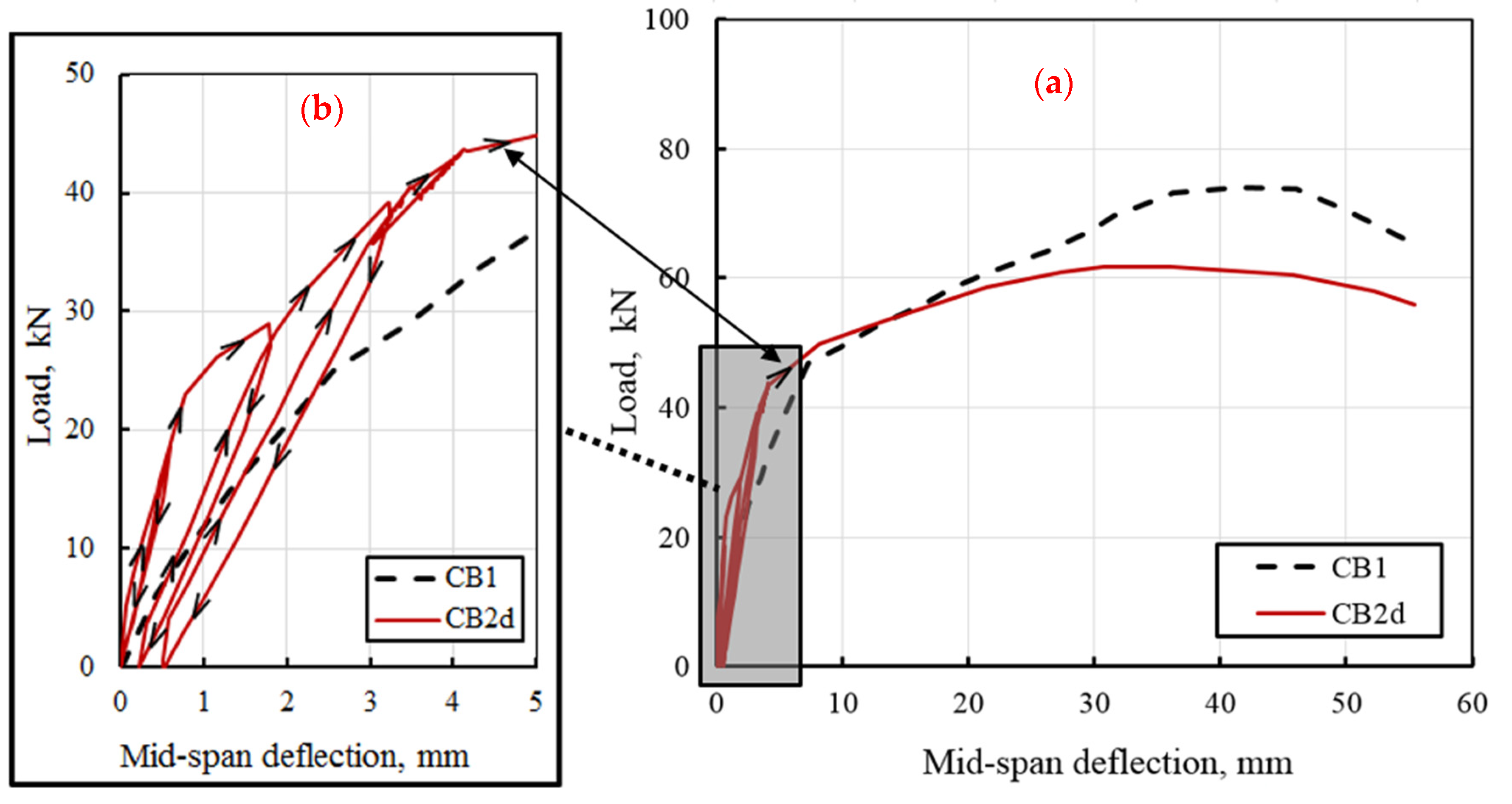
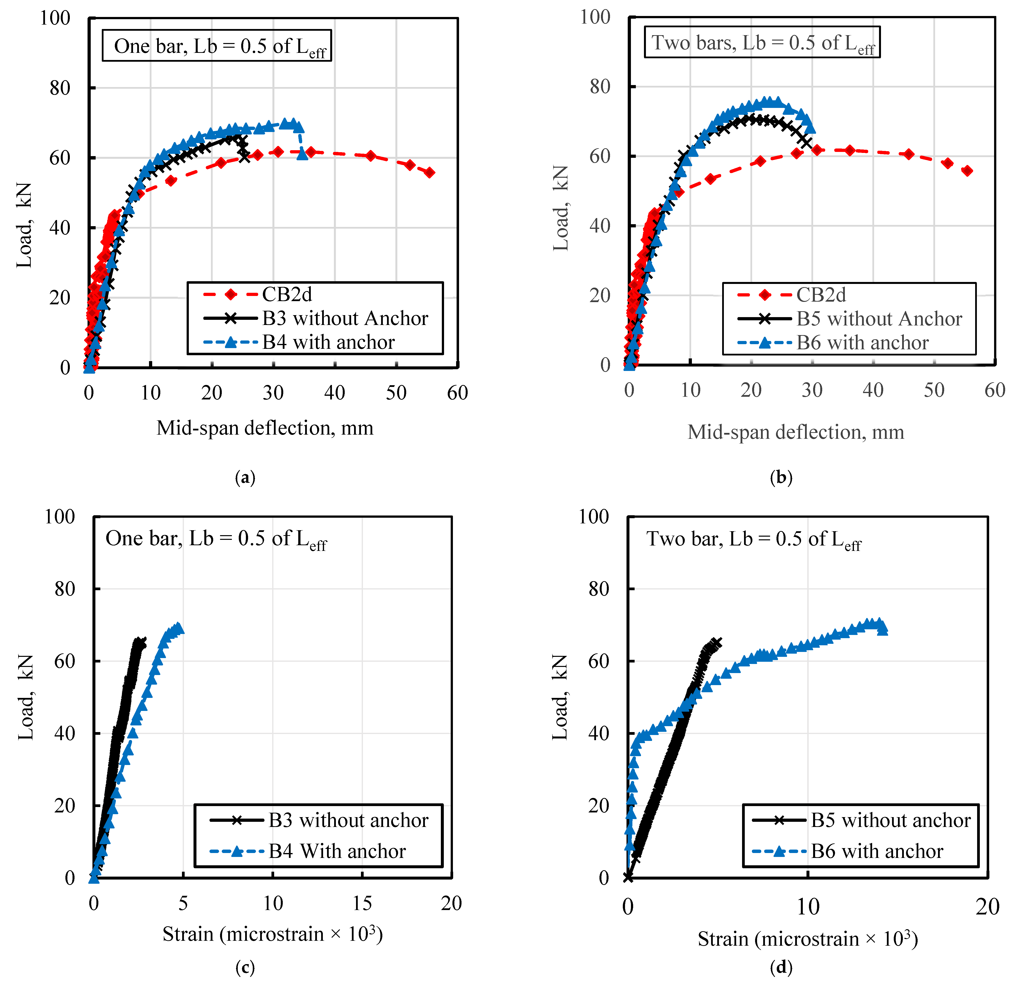
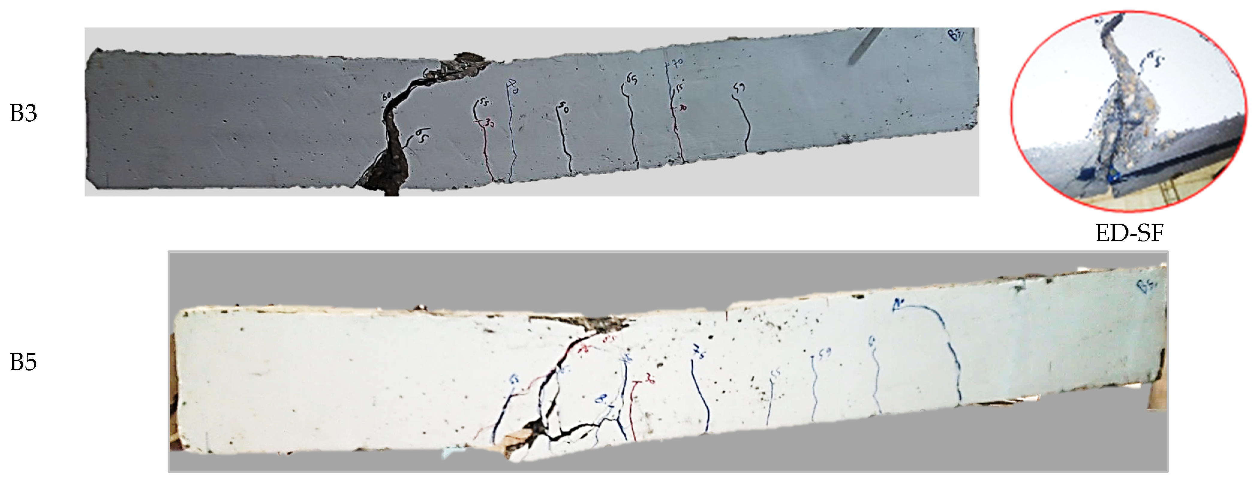
3.2.1. Effect of End Anchor Condition

Figure 12 and Figure 13 show the load deflection curves for the impact of end anchor conditions on both one and two GFRP bars, considering two different GFRP bar lengths. Specifically, Figure 12 depicts the load-deflection and load-strain curves for beams strengthened with a GFRP bar length of Lb = 0.5 of Leff, with and without anchors, for the cases of one and two bars. Using a single GFRP bar increased the maximum load (Pmax) in beams B3 and B4 compared to CB2d, with the maximum load (Pmax) increased by 6.8 and 12.6% for beams B3 and B4, respectively, as shown in Figure 12a. The maximum load (Pmax) increased from 62 kN in CB2d to approximately 70 kN and 75 kN, representing a 13% and 21% improvement in B5 and B6, respectively, as illustrated in Figure 12b for beams strengthened with two bars. The utilization of two bars demonstrated an enhancement in the maximum load capacity of the beam compared to the scenario with a single bar and the damaged beam (CB2d). The trend of load enhancement is further supported by the load-strain curves illustrated in Figure 12c,d. This finding aligns with similar outcomes reported in previous studies [35,36]. Moreover, the use of two bars resulted in a noticeable reduction in mid-span deflection compared to the one-bar scenario, irrespective of the presence of anchors. Conversely, for beams strengthened with a GFRP bar length of Lb = 0.8 of Leff, whether using one or two bars, a significant increase in the maximum load was observed compared to the case of Lb = 0.5 of Leff. In Figure 13a, the maximum load increased from 62 kN in CB2d to 93 kN and 94 kN in B6 and B7, respectively, with an increase of about 51%, in the case of a single GFRP bar and different anchor conditions (with and without anchor). On the other hand, in Figure 13b, the maximum load experienced a substantial rise from 62 kN to about 140 kN, reflecting a remarkable 126% increase when considering different anchor conditions (with and without anchors).
A noticeable decrease in mid-span deflection was observed when using two GFRP bars in comparison to using just one bar. The reduction in mid-span deflection is attributed to an increase in the number of bars, leading to improved resistance to stress. This increased resistance to stress results in the effective distribution of loads and stress along the length of the reinforcement, thereby enhancing its ability to carry applied loads. The Information provided suggests that the presence of end anchors has a positive impact on the maximum load of NSM GFRP bars. The anchors significantly contributed to the increase in maximum load and the decrease in mid-span deflection [37]. Figure 14 and Figure 15 detail the failure modes of the beams. Despite beams B3 and B4 having the same number of GFRP reinforcements, identical length, and cross-sectional area, and differing in anchor cases and peak loads, they exhibit similar failure patterns.
The failure of the specimen resulted from the compression of the upper concrete (CC) in the region subjected to pure bending moments near the load application points. Initially, minor hairline cracks emerged at the midpoint of the beam, gradually extending towards the neutral axis direction during the initial loading phase. With the introduction of additional external loads, new cracks formed. The crack pattern observed in Beam B3 closely resembled that of Beam B4. Ultimately, both beams B3 and B4 failed due to concrete crushing (CC) between the loading points. This failure was preceded by the distortion of GFRP strengthening and shear failure at the end of the GFRP bars. The primary observed failure mode involved the development of flexural and shear cracks near the locations of maximum bending moments, persisting as the applied load increased. It is noteworthy that the presence of end anchors in this specific configuration did not exhibit any noticeable effect on the failure mode of the beams.
The failure pattern of beam B6, which had an anchor, resembled the failure observed in beam B4. In contrast, beam B5 (without an anchor) experienced failure characterized by concrete crushing, accompanied by diagonal shear cracks initiating under loading points and extending towards the end of the strengthened GFRP bars, ultimately resulting in the separation of the concrete cover. It is noteworthy that the utilization of the end anchor in beam B6 successfully prevented concrete cover separation, consequently leading to an increase in the maximum load capacity compared to beam B5, as illustrated in Figure 12b, Figure 14 and Figure 15.

3.2.2. Effect of GFRP Bar Numbers

Figure 16 depicts the impact of the number of GFRP bars for a bar length (Lb) equal to 0.8 of Leff, with and without anchors. This analysis considers scenarios involving one bar with a diameter of 12 mm, two bars with a diameter of 12 mm, and three bars with a diameter of 10 mm. Notably, utilizing two bars with a diameter of 12 mm (designated as B9) resulted in a significant enhancement of the maximum load, exhibiting a 125% increase compared to the damaged reference beams CB2d. Specifically, the maximum load of beam B9 rose from 62 kN to 140 kN. Conversely, employing a single bar with a diameter of 12 mm (designated as B7) led to a 52% increase in the maximum load, elevating it from 62 kN to 94 kN. Meanwhile, the utilization of three bars with a diameter of 10 mm (designated as B11) resulted in a 106% increase in the maximum load, escalating from 62 kN to 128 kN, as illustrated in Figure 16a.
Utilizing two bars with diameters of 12 mm enhanced the maximum load capacity of the tested beams in comparison to the damaged reference beam, CB2d. In the case of a single bar with anchor B8, the maximum load increased from 62 kN to 93 kN, representing a 50% increase, as depicted in Figure 16b. The use of two bars with 12 mm diameters (B10) resulted in an increase in maximum load by 122% compared to CB2d and increased the mid-span deflection. Conversely, employing three GFRP bars with a diameter of 10 mm B12 led to a noticeable increase in maximum load, which increased by 109% compared to CB2d, but it led to a decrease of 6% in the maximum load of the tested beam compared to using two bars with a 12 mm diameter, and it also reduced mid-span deflection. Although the cross-sectional area was nearly the same, using three 10 mm bars increased the maximum load of the tested beam compared to using a single bar, whether with or without an anchor, and the damaged reference beam CB2d, as illustrated in Figure 16a,b. As indicated in Figure 14, beam B7 failed due to a diagonal shear crack, followed by concrete cover separation. In contrast, the use of an anchor in beam B8 prevented concrete cover separation, and the beam failed solely due to a diagonal shear crack (shear failure), as shown in Figure 15.
The impact of the anchor (applied in a manner similar to the bar numbers) was evident in shaping the failure patterns of both B9 and B10. In the case of B9, failure occurred because the concrete cover was crushed, followed by the debonding of the GFRP bars. In contrast, B10 exhibited a distinct effect from the anchor, preventing the separation of the concrete cover. The failure in B10 was attributed to the initiation of diagonal cracks under the loading points, propagating towards the end of the strengthening. This consistent observation of failure patterns was also noted in B11 and B12, as illustrated in Figure 14 and Figure 15.
These findings can be attributed to the increased stitching forces produced when using two bars in comparison to a single bar, as well as the increase in the cross-sectional area of NSM bars. On the other hand, in the case of three bars, the stitching forces generated decreased due to insufficient space between the bars (twice the bar’s diameter) to effectively resist the stitching forces on each side of the middle space. In summary, increasing the number of bars enhanced the maximum load capacity of the beam. However, for optimal efficiency, the spacing between bars should exceed twice the bar’s diameter. This outcome contradicts the findings in [38], which suggest that the distance between bars should not be less than 1.5 to 2 times the bar’s diameter.

3.2.3. Effect of GFRP Bar Length

Overall, the length of Glass Fiber Reinforced Polymer (GFRP) bars utilized for reinforcing RC beams had a notable impact on the strengthening process. This influence was evident in both the maximum load and maximum deflection, as illustrated in Figure 17. Generally, employing longer GFRP bars resulted in higher maximum loads. For instance, when utilizing a single GFRP bar with an anchor, increasing the GFRP bar length (Lb) from 0.5 to 0.8 of Leff led to a significant rise in the maximum load—from 69 kN to 94 kN, marking a 36% increase, as depicted in Figure 17a.
Additionally, there was an increase in the maximum deflection from 34.7 mm to 39.65 mm. This observation is depicted in Figure 17b, where, in the case of a single bar without an anchor, the maximum load for beam B7 saw a 40% increase compared to beam B3. The elongation of bars along the span of the beam provided enhanced reinforcement against applied loads and improved post-cracking resistance.
In the scenario involving two bars, there was a notable improvement in the maximum load value with an increase in bar length from Lb = 0.5 to Lb = 0.8 of Leff, as illustrated in Figure 17c,d, respectively. Increasing the GFRP bar length (Lb) from 0.5 to 0.8 of Leff led to a noticeable increase in the maximum load from 75 kN to 138 kN, with an increase of 84%, as seen in Figure 17c. On the other hand, in the case of two bars without an anchor, the maximum load for B9 increased 94% compared to B5. The extended length of the GFRP bars contributed to the enhanced flexural strength of the RC beams by effectively increasing the lever arm (moment arm) for resisting bending. This led to higher flexural capacity and improved performance under bending loads.
Furthermore, longer GFRP bars played a crucial role in controlling cracks within the RC beams. By extending these bars along the length of the beam, they could distribute stress and prevent the formation of large cracks, ultimately enhancing the durability of the beams [39,40].

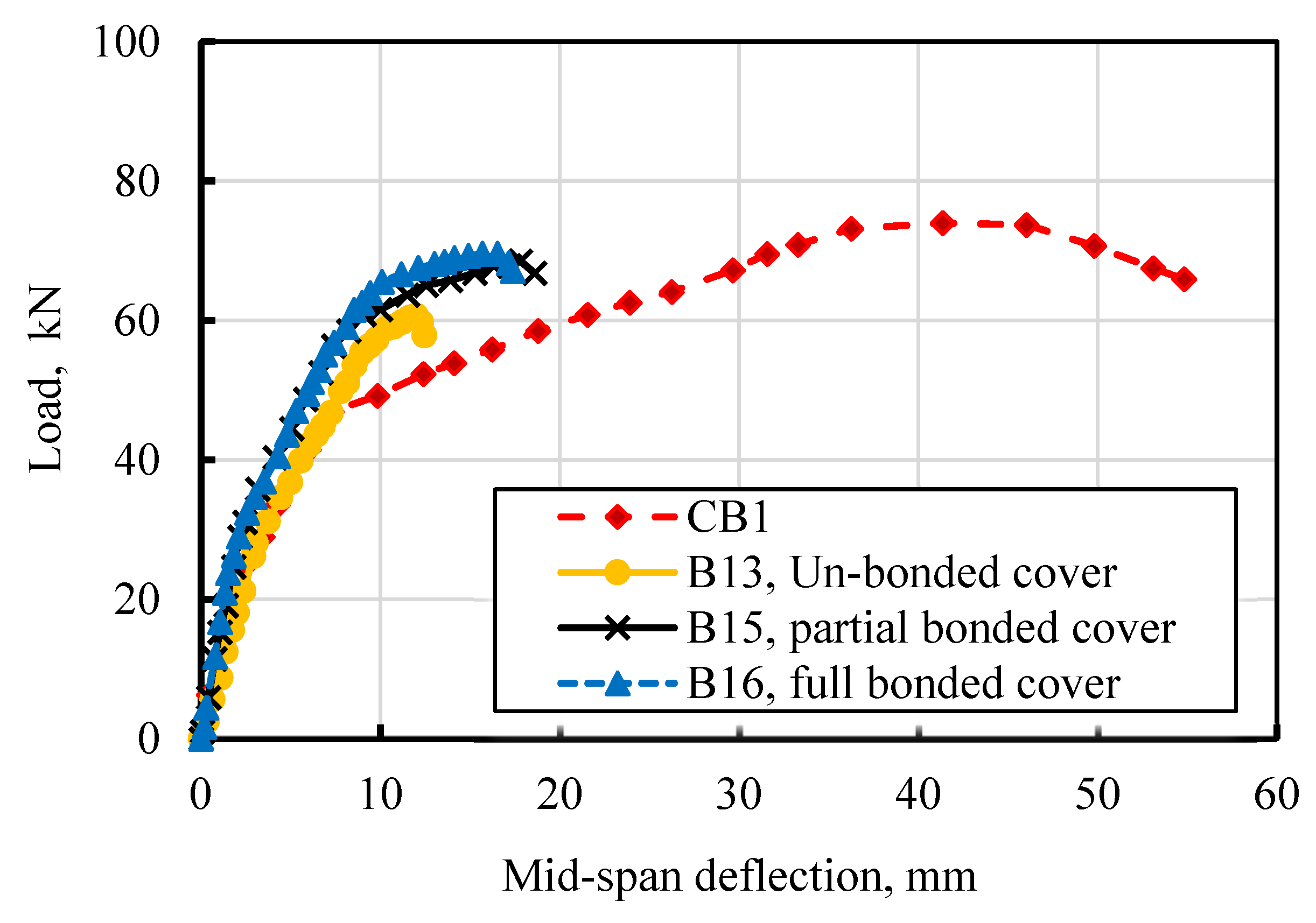
3.2.4. Effect of Concrete Cover Bonding Conditions

The following section presents the load-deflection characteristics and failure patterns of undamaged beams subjected to flexural loading under various concrete cover conditions, aiming to comprehend their behavior. In Figure 18, the load-deflection curve illustrates the impact of concrete cover bonding conditions for two bars with and without anchors, specifically for Lb = 0.5 of Leff. The concrete cover was applied 28 days after casting the beams.
The use of concrete cover, whether in partial or full bonding, significantly enhanced the maximum load capacity of the tested beams. Depending on the type of bonding employed, the maximum load increased by up to 17%. Furthermore, concrete cover bonding contributed to the improvement of mid-span deflection, enhancing the ductility of the beam. Through this technique, the mid-span deflection increased from 12 mm to approximately 18.5 mm, depending on the bonding method, as shown in Figure 18. In general, both partial bonding and full bonding of the concrete cover strengthened the bonding and increased the maximum load compared to beams with an unbonded concrete cover. For instance, the maximum loads of beams B15 and B16 increased by 14% and 16.5%, respectively, with partial and full bonding, compared to B13 without bonding. Moreover, full bonding resulted in a 2% increase in maximum load compared to partial bonding. The mode of failure for beams B13, B15, and B16 (without anchors) is depicted in Figure 19, with diagonal cracks followed by concrete cover separation being the predominant failure mechanism.

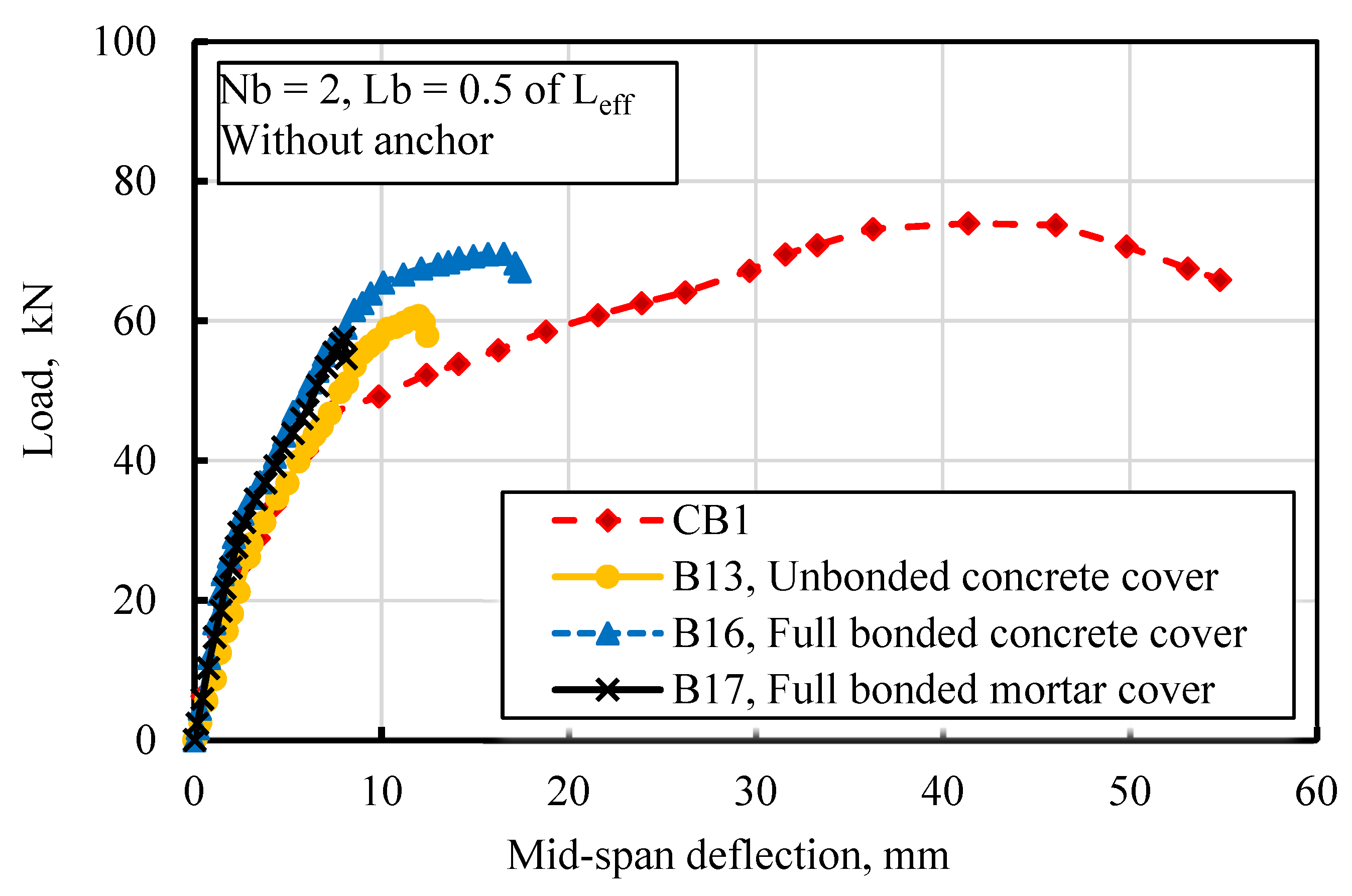
3.2.5. Effect of Concrete Cover Material Type

Figure 20 presents the outcomes of tests conducted on beams B13, B16, and B17 in their original undamaged condition. In the case of B13, the concrete cover was applied without epoxy bonding, whereas B16 had complete epoxy bonding for its concrete cover. On the other hand, beam B17 featured a mortar cover cast with full epoxy bonding. The results indicate that beam B17, with a mortar cover, exhibited lower values for both maximum load and deflection compared to beam B16, which had a concrete cover with full epoxy bonding. The maximum load of beam B17, with a mortar cover, decreased by 17% compared to B16 with a concrete cover. This suggests that utilizing a mortar cover was not effective in reinforcing the beam using the NSM technique. The failure mode of beam B17 is illustrated in Figure 21 [12].

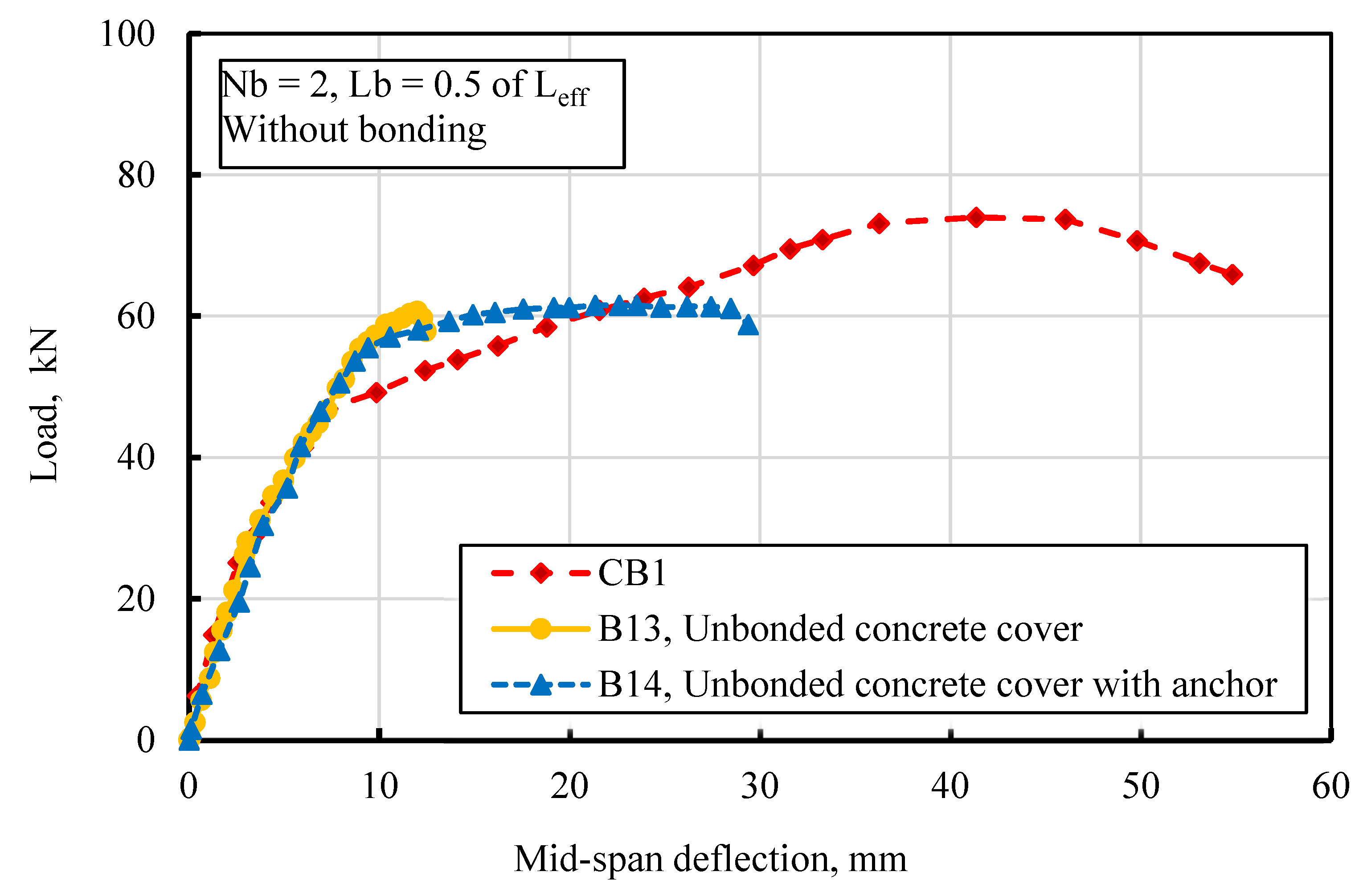
3.2.6. Effect of End Anchor Conditions on Unbonded Concrete Cover

Figure 22 illustrates a comparison between beams reinforced with a non-bonded concrete cover, with and without an anchor. The results clearly indicate that the utilization of the end anchor in B14 significantly improves the ductility of the beam compared to the behavior observed in beam B13, which increased by 135%; on the other hand, there was a slight effect on the maximum load, which increased by 2.5%.
The failure mode exhibited by beam B14 is shown in Figure 23. This failure occurred due to shear failure induced by diagonal shear cracks initiated at loading points and propagated towards the end of the strengthening section. This observation of the failure mode aligns with findings from previous research studies [2,20,41]

4. Conclusions

Based on the findings presented in this study, several key conclusions can be drawn:
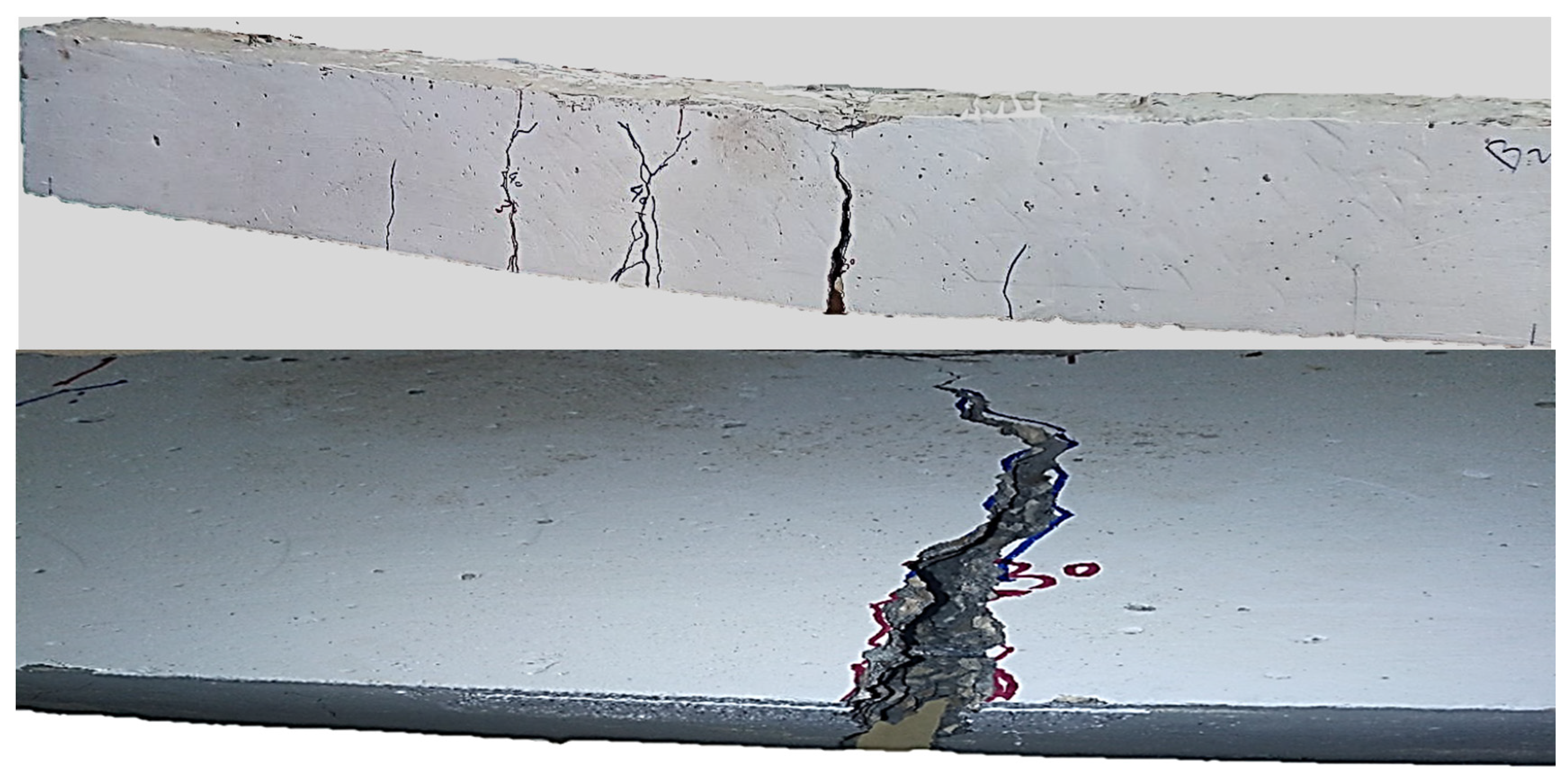
  • Pre-damaged beams experienced a significant decrease in both cracking and maximum load, indicating the substantial impact of structural damage.
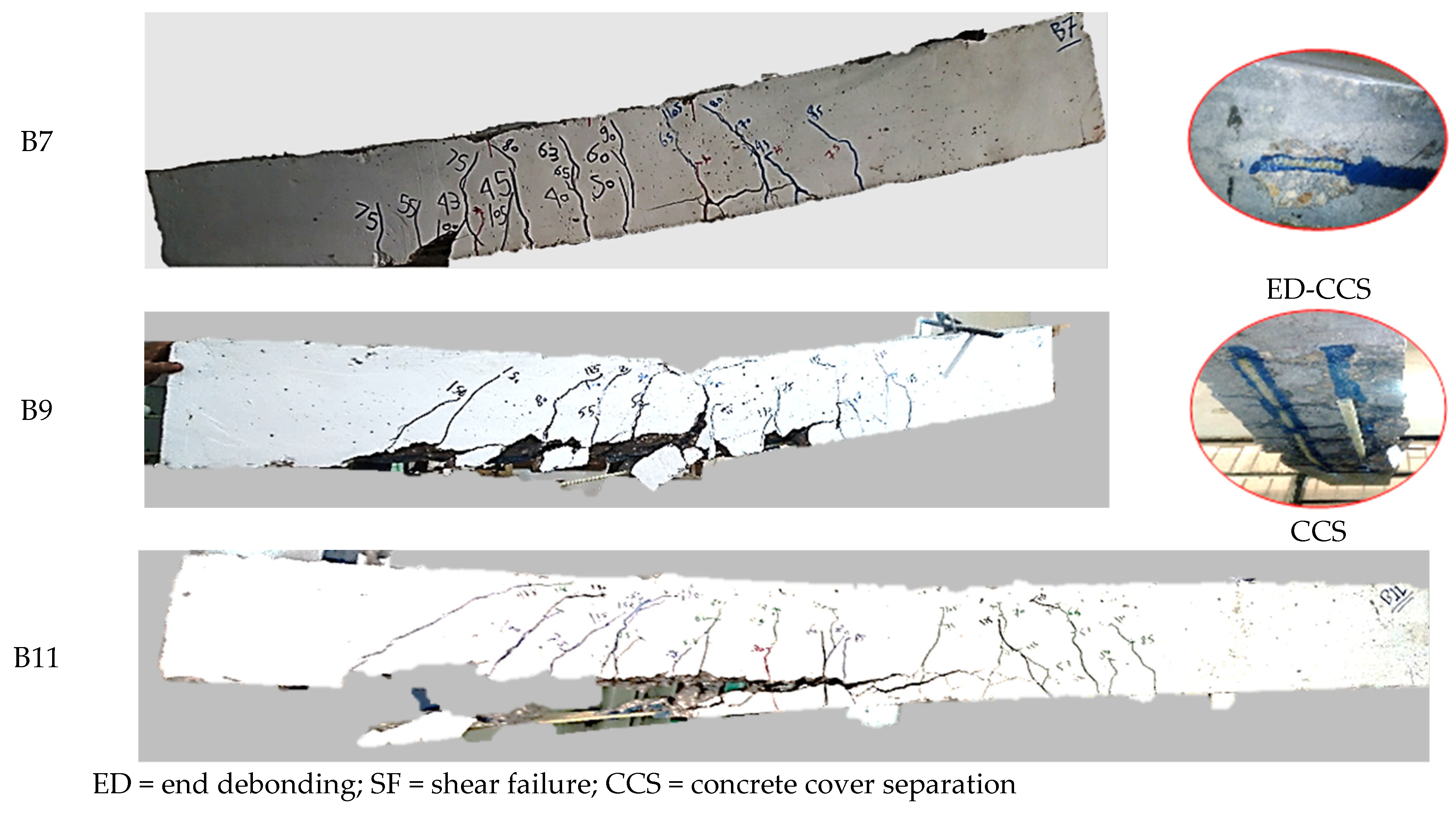
  • The utilization of anchors in NSM strengthening proved highly effective in preventing concrete cover separation, resulting in a notable increase in maximum load and a concurrent reduction in mid-span deflection.
  • Increasing the NSM bar length up to 0.8 of Leff emerged as a critical factor, resulting in a noticeable enhancement in the maximum load in the strengthened beams, confirming the significance of bar length in structural performance.
  • The number of GFRP bars significantly affected the maximum load and ductility, with the study recommending the use of two bars over three for superior results in terms of both maximum load and ductility.
  • A maximum enhancement of 122% in the maximum load was recorded for the beam strengthened with two GFRP bars of 12 mm in diameter and bar length (Lb) equal to 0.8 of Leff with anchor.
  • The study revealed that concrete covering, whether bonded or not, surpassed cement mortar covering in terms of maximum loading and deflection.
  • End bonding of the concrete cover and the end of the strengthening bars was found to be more effective than bonding in the area of maximum moment.
  • Achieving a 135% improvement in maximum loads entailed a cost increase of 180%.
  • There was a high level of agreement between the numerical validation and the experimental results, indicating the reliability of the findings obtained in this study.

Author Contributions

Conceptualization, H.M.E.-E., S.S.E.A., H.A.S. and R.M.R.; Methodology, H.M.E.-E., B.A., S.S.E.A. and R.M.R.; Validation, H.M.E.-E.; Formal analysis, H.M.E.-E., B.A. and R.M.R.; Investigation, B.A. and R.M.R.; Data curation, H.M.E.-E., B.A., S.S.E.A., H.A.S. and R.M.R.; Writing—original draft, H.M.E.-E., B.A. and R.M.R.; Writing—review & editing, H.M.E.-E., S.S.E.A., H.A.S. and R.M.R. All authors have read and agreed to the published version of the manuscript.

Funding

This research received no external funding

Data Availability Statement

All the data required are reported in this manuscript.

Conflicts of Interest

The authors declare no conflict of interest

References

  1. El-Sisi, A.A.; El-Emam, H.M.; El-Kholy, A.E.I.; Ahmad, S.S.; Sallam, H.M.; Salim, H.A. Structural Behavior of RC Beams Containing Unreinforced Drilled Openings with and without CFRP Strengthening. Polymers 2022, 14, 2034. [Google Scholar] [CrossRef]
  2. Elbelbisi, A.H.; El-Sisi, A.A.; Hassan, H.A.; Salim, H.A.; Shabaan, H.F. Parametric Study on Steel–Concrete Composite Beams Strengthened with Post-Tensioned CFRP Tendons. Sustainability 2022, 14, 15792. [Google Scholar] [CrossRef]
  3. Badawi, M.; Soudki, K. Flexural strengthening of RC beams with prestressed NSM CFRP rods–experimental and analytical investigation. Constr. Build. Mater. 2009, 23, 3292–3300. [Google Scholar] [CrossRef]
  4. Barros, J.A.; Ferreira, D.R.; Fortes, A.S.; Dias, S.J. Assessing the effectiveness of embedding CFRP laminates in the near surface for structural strengthening. Constr. Build. Mater. 2006, 20, 478–491. [Google Scholar] [CrossRef]
  5. Bilotta, A.; Ceroni, F.; Nigro, E.; Pecce, M. Efficiency of CFRP NSM strips and EBR plates for flexural strengthening of RC beams and loading pattern influence. Compos. Struct. 2015, 124, 163–175. [Google Scholar] [CrossRef]
  6. Blaschko, M.; Zilch, K. Rehabilitation of concrete structures with CFRP strips glued into slits. In Proceedings of the Twelfth International Conference of Composite Materials, ICCM, Paris, France, 5–9 July 1999. [Google Scholar]
  7. De Lorenzis, L.; Lundgren, K.; Rizzo, A. Anchorage length of near-surface mounted fiber-reinforced polymer bars for concrete strengthening-experimental investigation and numerical modeling. ACI Struct. J. 2004, 101, 269–278. [Google Scholar]
  8. De Lorenzis, L.; Nanni, A.; La Tegola, A. Strengthening of reinforced concrete structures with near surface mounted FRP rods. In Proceedings of the International Meeting on Composite Materials, PLAST, Milan, Italy, 9–11 May 2000; pp. 9–11. [Google Scholar]
  9. De Lorenzis, L.; Teng, J.G. Near-surface mounted FRP reinforcement: An emerging technique for strengthening structures. Compos. Part B Eng. 2007, 38, 119–143. [Google Scholar] [CrossRef]
  10. El-Hacha, R.; Gaafar, M. Flexural strengthening of reinforced concrete beams using prestressed, near-surfacemounted CFRP bars. PCI J. 2011, 56, 134–151. [Google Scholar] [CrossRef]
  11. Galati, D.; De Lorenzis, L. Effect of construction details on the bond performance of NSM FRP bars in concrete. Adv. Struct. Eng. 2009, 12, 683–700. [Google Scholar] [CrossRef]
  12. El-Emam, H.; El-Sisi, A.; Reda, R.; Bneni, M.; Seleem, M. Effect of concrete cover thickness and main reinforcement ratio on flexural behavior of RC beams strengthened by NSM-GFRP bars. Frat. Ed. Integrità Strutt. 2020, 14, 197–210. [Google Scholar] [CrossRef]
  13. Mukhopadhyaya, P.; Swamy, N. Interface shear stress: A new design criterion for plate debonding. J. Compos. Constr. 2001, 5, 35–43. [Google Scholar] [CrossRef]
  14. Nguyen, D.M.; Chan, T.K.; Cheong, H.K. Brittle failure and bond development length of CFRP-concrete beams. J. Compos. Constr. 2001, 5, 12–17. [Google Scholar] [CrossRef]
  15. Rahman, M.M.; Jumaat, M.Z. The Effect of CFRP laminate length for strengthening the tension zone of the reinforced concrete T-beam. J. Sci. Res. Rep. 2013, 2, 626–640. [Google Scholar] [CrossRef]
  16. Reda, R.; Sharaky, I.; Ghanem, M.; Seleem, M.; Sallam, H. Flexural behavior of RC beams strengthened by NSM GFRP Bars having different end conditions. Compos. Struct. 2016, 147, 131–142. [Google Scholar] [CrossRef]
  17. Sen, R.; Liby, L.; Mullins, G. Strengthening steel bridge sections using CFRP laminates. Compos. Part B Eng. 2001, 32, 309–322. [Google Scholar] [CrossRef]
  18. Shabana, I.; Sharaky, I.; Khalil, A.; Hadad, H.; Arafa, E. Flexural response analysis of passive and active near-surface-mounted joints: Experimental and finite element analysis. Mater. Struct. 2018, 51, 1–15. [Google Scholar] [CrossRef]
  19. Sharaky, I.; Baena, M.; Barris, C.; Sallam, H.; Torres, L. Effect of axial stiffness of NSM FRP reinforcement and concrete cover confinement on flexural behaviour of strengthened RC beams: Experimental and numerical study. Eng. Struct. 2018, 173, 987–1001. [Google Scholar] [CrossRef]
  20. Sharaky, I.; Reda, R.; Ghanem, M.; Seleem, M.; Sallam, H. Experimental and numerical study of RC beams strengthened with bottom and side NSM GFRP bars having different end conditions. Constr. Build. Mater. 2017, 149, 882–903. [Google Scholar] [CrossRef]
  21. Sharaky, I.; Selmy, S.; El-Attar, M.; Sallam, H. The influence of interaction between NSM and internal reinforcements on the structural behavior of upgrading RC beams. Compos. Struct. 2020, 234, 111751. [Google Scholar] [CrossRef]
  22. Sharaky, I.A.; Torres, L.; Baena, M.; Miàs, C. An experimental study of different factors affecting the bond of NSM FRP bars in concrete. Compos. Struct. 2013, 99, 350–365. [Google Scholar] [CrossRef]
  23. Sharaky, I.A.; Torres, L.; Comas, J.; Barris, C. Flexural response of reinforced concrete (RC) beams strengthened with near surface mounted (NSM) fibre reinforced polymer (FRP) bars. Compos. Struct. 2014, 109, 8–22. [Google Scholar] [CrossRef]
  24. Sharaky, I.A.; Torres, L.; Sallam, H. Experimental and analytical investigation into the flexural performance of RC beams with partially and fully bonded NSM FRP bars/strips. Compos. Struct. 2015, 122, 113–126. [Google Scholar] [CrossRef]
  25. Soliman, S.M.; El-Salakawy, E.; Benmokrane, B. Flexural behaviour of concrete beams strengthened with near surface mounted fibre reinforced polymer bars. Can. J. Civ. Eng. 2010, 37, 1371–1382. [Google Scholar] [CrossRef]
  26. Soudki, K.; Alkhrdaji, T. Guide for the design and construction of externally bonded FRP systems for strengthening concrete structures (ACI 440.2 R-02). In Structures Congress: Metropolis and Beyond; American Society of Civil Engineers: Reston, VA, UAS, 2005; pp. 1–8. [Google Scholar]
  27. Tang, W.; Balendran, R.; Nadeem, A.; Leung, H. Flexural strengthening of reinforced lightweight polystyrene aggregate concrete beams with near-surface mounted GFRP bars. Build. Environ. 2006, 41, 1381–1393. [Google Scholar] [CrossRef]
  28. Ombres, L.; Mazzuca, P. Residual Flexural Behavior of PBO FRCM Strengthened Reinforced Concrete Beams after Exposure to Elevated Temperatures. J. Compos. Constr 2024, 28, 04023063. [Google Scholar] [CrossRef]
  29. Carloni, C.; Verre, S.; Sneed, L.H.; Ombres, L. Open issues on the investigation of PBO FRCM-Concrete debonding. Compos. Struct. 2022, 299, 116062. [Google Scholar] [CrossRef]
  30. BS EN, 12390-12393:2009; Testing Hardened Concrete-Compressive Strength of Test Specimens, Part 6. British Standards: London, UK, 2011.
  31. BS EN, 12390-12396; Testing Hardened Concrete. Tensile Splitting Strength of Test Specimens, Part 6. British Standards: London, UK, 2009.
  32. BS EN, 12390-12395; Testing Hardened Concrete. Flexural Strength of Test Specimens, Part 5. British Standards: London, UK, 2009.
  33. ACI 318-11; Building Code Requirements for Structural Concrete. American Concrete Institute: Farmington Hills, MI, USA, 2011.
  34. Yu, H.; Bai, Y.L.; Dai, J.G.; Gao, W.Y. Finite element modeling for debonding of FRP-to-concrete interfaces subjected to mixed-mode loading. Polymers 2017, 9, 438. [Google Scholar] [CrossRef] [PubMed]
  35. Wu, Z.; Wang, X.; Iwashita, K. State-of-the-art of advanced FRP applications in civil infrastructure in Japan. Compos. Polycon 2007, 37, 1–17. [Google Scholar]
  36. Zhang, S.S.; Yu, T.; Chen, G. Reinforced concrete beams strengthened in flexure with near-surface mounted (NSM) CFRP strips: Current status and research needs. Compos. Part B Eng. 2017, 131, 30–42. [Google Scholar] [CrossRef]
  37. Soliman, S.M.; El-Salakawy, E.; Benmokrane, B. Bond performance of near-surface-mounted FRP bars. J. Compos. Constr. 2011, 15, 103–111. [Google Scholar] [CrossRef]
  38. Zhou, Y.; Gou, M.; Zhang, F.; Zhang, S.; Wang, D. Reinforced concrete beams strengthened with carbon fiber reinforced polymer by friction hybrid bond technique: Experimental investigation. Mater. Des. 2013, 50, 130–139. [Google Scholar] [CrossRef]
  39. EL-Emam, H.; El-Sisi, A.; Bneni, M.; Ahmad, S.S.; Sallam, H.E.D.M. Effects of tensile reinforcing steel ratio and Near-Surface-Mounted bar development length on the structural behavior of strengthened RC beams. Lat. Am. J. Solids Struct. 2020, 17. [Google Scholar] [CrossRef]
  40. Almusallam, T.H.; Elsanadedy, H.M.; Al-Salloum, Y.A.; Alsayed, S.H. Experimental and numerical investigation for the flexural strengthening of RC beams using near-surface mounted steel or GFRP bars. Constr. Build. Mater. 2013, 40, 145–161. [Google Scholar] [CrossRef]
  41. Hassan, T.; Rizkalla, S. Bond mechanism of NSM FRP bars for flexural strengthening of concrete structures. ACI Struct. J. 2004, 101, 830–839. [Google Scholar]
Figure 1. Details of the control beam.
Buildings 14 00723 g001
Figure 2. Details of the strengthened beam without anchor (a) one bar, (b) two bars and (c) three bars (all dimensions are in mm).
Buildings 14 00723 g002
Figure 3. Details of the strengthened beam with anchor (a) 2 anchor bolts, (b) 3 anchor bolts and (c) 4 anchor bolts (all dimensions are in mm).
Buildings 14 00723 g003aBuildings 14 00723 g003b
Figure 4. The anchor details.
Buildings 14 00723 g004
Figure 5. Strengthening setup and procedures. (a) (B7) beams with one bar without anchor, (b) (B9) beam with two bars without anchor, (d) (B12) beam with three bars with anchor, (e) (B10) beam with two bars with anchor and (c) (B17) beam with mortar cover and fully bonded; (f) (B8) beam with single bar with anchor.
Buildings 14 00723 g005aBuildings 14 00723 g005b
Figure 6. Test setup and instruments.
Buildings 14 00723 g006
Figure 7. FE modeling; (a) The simulated beam, (b) Strengthening details; NSM GFRP bars, epoxy, anchor, and (c) predicted numerical failure mode.
Buildings 14 00723 g007
Figure 8. Numerical validation.
Buildings 14 00723 g008
Figure 9. Load deflection curves for beams CB1 and CB2d; (a) fully load deflection, and (b) cyclic loading/unloading of CB2d.
Buildings 14 00723 g009
Figure 10. Mode of failure of beam CB1.
Buildings 14 00723 g010
Figure 11. Mode of failure of beam CB2d.
Buildings 14 00723 g011
Figure 12. Effect of end anchor; (a) load-deflection of one bar, Lb = 0.5 of Leff, (b) load-deflection of two bars, Lb = 0.5 of Leff, (c) load-strain of one bar, Lb = 0.5 of Leff, and (d) load-strain of two bars, Lb = 0.5 of Leff.
Buildings 14 00723 g012
Figure 13. Effect of end anchor; (a) load-deflection of one bar, Lb = 0.8 of Leff, (b) load-deflection of two bars, Lb = 0.8 of Leff.
Buildings 14 00723 g013
Figure 14. Mode of failure of beams B3, B5, B7, B9, and B11 without end anchorage.
Buildings 14 00723 g014aBuildings 14 00723 g014b
Figure 15. Mode of failure of beams B4, B6, B8, B10, and B12 with end anchorage.
Buildings 14 00723 g015aBuildings 14 00723 g015b
Figure 16. Effect of GFRP bar number; (a) load-deflection for beams without anchor, and (b) load-deflection for beams with anchor.
Buildings 14 00723 g016
Figure 17. Effect of GFRP bar length; (a) load-deflection of one bar with anchor, (b) load-deflection of one bar without anchor, (c) load-deflection of two bars with anchor, and (d) load-deflection of two bars without anchor.
Buildings 14 00723 g017
Figure 18. Effect of bonding conditions on concrete cover.
Buildings 14 00723 g018
Figure 19. Mode of failure of beams B13, B15, and B16.
Buildings 14 00723 g019
Figure 20. Effect of the concrete cover material type.
Buildings 14 00723 g020
Figure 21. Mode of failure of beam B17.
Buildings 14 00723 g021
Figure 22. Effect of End Anchor Conditions for Unbonded Concrete Cover.
Buildings 14 00723 g022
Figure 23. Mode of failure of beam B14.
Buildings 14 00723 g023
Table 1. Configuration of the tested beams.
GroupBeam IDDetails of NSM GFRP BarsCover Details, 3 cmDamage
di, mmNbLeff, mmAnchoring systemTypeCastingBonding
First groupCB1----CCWith beam -W/0ut
CB2dW
Second groupB31211100-CCWith beam-W
B41211100WA
B51221100-
B61221100WA
B71211800-
B81211800WA
B91221800-
B101221800WA
B111031800-
B121031800WA
Third groupB131221100-CCAfter 28 daysW/0utW/0ut
B14WACCW/0ut
B15-CCPartial
B16-CCFull
B17-MCFull
WA = with Anchor, W/out = without, di = diameter of NSM GFRP bars, Nb = number of bars, CC = concrete cover, and MC = mortar cover.
Table 2. Mix proportion of concrete for cubic meter.
MaterialCement, kgW/CSand, kgCoarse Aggregate, kgWater, Lit
Dolomite 10 mmDolomite 20 mm
Amount3750.48635577.5577.5180
Table 3. Mechanical properties of the epoxy used.
PropertiesTensile StrengthCompressive StrengthBending Strength
Yield strength, MPa5486.2138
Strain at yield, %2.553.8
Elastic modulus, MPa303426203724
Ultimate strength, MPa55.286.2138
Rapture strain, %3.555
Disclaimer/Publisher’s Note: The statements, opinions and data contained in all publications are solely those of the individual author(s) and contributor(s) and not of MDPI and/or the editor(s). MDPI and/or the editor(s) disclaim responsibility for any injury to people or property resulting from any ideas, methods, instructions or products referred to in the content.

