Article

Study on Structural Parameter Sensitivity and the Force Transmission Mechanism of Steel–Concrete Joints in Hybrid Beam Bridges

1
Department of Bridge Engineering, College of Civil Engineering, Tongji University, No. 1239 Siping Road, Shanghai 200092, China
2
Jiangxi Communications Design and Research Institute Co., Ltd., Nanchang 330052, China
3
China Railway Shanghai Design Institute Group Co., Ltd., Shanghai 200070, China
*
Author to whom correspondence should be addressed.
Buildings 2024, 14(3), 708; https://doi.org/10.3390/buildings14030708
Submission received: 21 January 2024 / Revised: 29 February 2024 / Accepted: 29 February 2024 / Published: 6 March 2024

Abstract

:
In this study, a refined model of the Shanghai Damaogang Bridge’s (hybrid beam type) box deck joints is established. The correctness of the model is verified by construction monitoring. For the front and back bearing plates, the force performance of the joint members under the most unfavorable loads is investigated, and the force transmission mechanism is analyzed. The influence of the bearing plate thickness and the joints’ stiffness on the stress distribution of the joint members, the internal force of the joints, and the force-transfer efficiency is investigated by the method of controlling variables, and the optimal structural parameters of the nodes are also studied. The results show that, within the proximity of the back bearing plate, the thickness of the back bearing plate affects stress distribution in the joint. The increased stiffness of the welding studs makes the range of shear force along the bridge direction of the top and bottom welding studs larger, and the longitudinal distribution of welding stud shear force is more uneven. The concrete structure bears a higher proportion of the internal force in the joint compared to the steel structure.

1. Introduction

Hybrid beam bridges employ steel beams instead of concrete beams in the mid-span to reduce the self-weight of the main beam, therefore improving its span capacity and fully leveraging the material properties of both steel and concrete. Unlike composite beam bridges that utilize multiple materials on the same section [1,2,3], hybrid beam bridges utilize different materials along the span direction. Therefore, steel–concrete joints are key structures within hybrid beam bridges, and the rationality of these joints directly impacts the safety of the bridge. With the widespread adoption of the hybrid beam bridge, such as the Xupu Bridge in Shanghai, Yongjiang Railway Bridge in Ningbo, Mawei Bridge in Fuzhou, and so on, scholars are increasingly focusing on the mechanical properties of steel–concrete joints.
The overall mechanical performance and force transfer mechanism of the joint are crucial aspects in the research on the hybrid beam joints [4]. Tang et al. [5] conducted a finite element analysis to study the force characteristics and structural parameters of the cellular steel–concrete joint in the back bearing plate of a hybrid girder cable-stayed bridge. Zhang et al. [6] performed model tests and finite element analyses on the steel–concrete joints in the Wusu Bridge, examining the force transmission mechanism of the joints in a hybrid beam cable-stayed bridge. Xing et al. [7] conducted model tests on the steel–concrete joints in a cable-stayed bridge, establishing a finite element analysis model using ANSYS to discuss the simulation analysis method used for the steel–concrete joints in a hybrid beam cable-stayed bridge. Zhang et al. [8], based on the elastic continuous medium layer method and considering the slip between the steel structure and the concrete and the local pressure of the concrete, proposed a theoretical calculation method for the cellular steel–concrete joints within a back bearing plate in a hybrid beam, and analyzed the factors affecting the force transmission mechanism of the joint using the finite element method. He et al. [9] studied the mechanical properties of steel–concrete joints using UHPC grouting in single cable-plane hybrid beam cable-stayed bridges through model tests and numerical analyses. Yang et al. [10] conducted model tests on the joints in a high-speed railway hybrid beam cable-stayed bridge, proposed simplified calculation formulas for deflection and rotation, and analyzed the thickness of the bearing plate at the joint based on the finite element method. Pu et al. [11] investigated the fatigue performance of the joints in a new type of long-span railway cable-stayed bridge based on model tests and numerical analyses. The results show that the thickness of the end bearing plate significantly influences the fatigue performance of the joint, and a recommended thickness range of the end bearing plate is provided. Gu et al. [12] studied the structural performance of the steel–concrete joints in a hybrid beam cable-stayed bridge through model tests and the finite element method, analyzing the force transmission mechanism of the joints. Yao et al. [13] proposed a new type of steel–concrete joint for long-span railway hybrid beam cable-stayed bridges, conducting model tests and studying the influence of different structural parameters on the mechanical properties of the joint using the finite element method. Xu et al. [14] established a full-scale model of a new type of joint, performed static bending tests, and analyzed the influence of material damage plasticity on the mechanical properties of the new joint based on the finite element method. Zhou et al. [15] conducted model tests and a finite element analysis on the joints in a railway bridge, studying the force transmission mechanism and the influence of structural design parameters on the mechanical properties of the joint. Liang et al. [16] conducted half-scale model tests on the joint between a steel–concrete composite beam and concrete beam in a large-span cable-stayed bridge. They established a finite element model to study the crack development law of the joint and proposed a new type of joint with an improved crack resistance performance. However, most of these studies are centered on the joints in cable-stayed bridges, and the construction methods and stress characteristics of hybrid continuous beam bridges differ from those of cable-stayed bridges. Further investigations are required to study the structural parameter sensitivity and force transmission mechanism of steel–concrete joints in hybrid beam bridges.
The design and mechanical properties of the internal structure of the joint are also important aspects in the studying joints. He et al. [17] introduced a new type of steel–concrete joint for hybrid beam cable-stayed bridges using perfo-bond connectors and analyzed its mechanical properties by carrying out push-out tests on perfo-bond connectors and 1:2 model tests on the joint. He et al. [18] investigated the failure mode, ductility, and other mechanical properties of perfo-bond connectors in hybrid beam cable-stayed bridge joints. They proposed a method for predicting the ultimate resistance of perfo-bond connectors using the shear failure of the dowel. Jin et al. [19] designed 39 push-out specimens to study the influence of various parameters such as hole size and hole shape on the mechanical properties of large perfo-bond connectors in the steel–concrete joints in hybrid bridges. They proposed a formula for calculating the shear capacity of the encased perfo-bond connector. Zou et al. [20] developed a finite element model for push-out tests on perfo-bond connectors in the steel–concrete joints in hybrid bridges and studied the shear performance and force transmission mechanism of perfo-bond connectors. Based on numerical simulation and theoretical methods, Zou et al. [21] further delved into the mechanical behavior of perfo-bond connectors at the joint and gave a simplified calculation method for determining the maximum slip, effective utilization rate, and load ratio. Zhou et al. [22] designed a full-scale model of a joint from a hybrid beam cable-stayed bridge and conducted fatigue tests based on this model to study the fatigue performance of the joint’s steel structure, concrete structure, and connectors.
In addition to the aforementioned considerations, scholars have also studied the influence of the joint’s position on the bridge structure. Zhao et al. [23] examined the influence of joint positioning on the nonlinear stability of the construction process in large-span hybrid beam cable-stayed bridges. He et al. [24] proposed a method for determining the optimal joint location based on the concept of system equivalence, and the effectiveness of the method was verified by some case studies.
Hybrid beams find application in cable-stayed bridges, suspension bridges, and beam bridges [25]. In different bridge types, the force characteristics of the joints in the hybrid beams are different. In cable-stayed bridges, the axial force generated by cable action in the main beam is conducive to the connection between the steel structure and the concrete in the joint. While in continuous beam bridges, the main beam primarily experiences shear force and a bending moment. To ensure joint reliability, multiple longitudinal prestressed tendons need to be placed in this section. At present, steel–concrete hybrid structures are mostly employed in cable-stayed bridges and relatively less in beam bridges. Existing studies have primarily focused on the hybrid beam joints in cable-stayed bridges. However, because of the excellent spanning capacity and economic performance of hybrid beam bridges, more and more hybrid beam bridges have been built, but as mentioned above, the joint structure used in beam bridges is complex, and the internal force transmission and distribution are not clear yet. Moreover, most of the above studies are based on finite element models, while this study establishes a finite element model of the joints based on the engineering background of the Damaogang Bridge in Shanghai, and verifies the correctness of the model through construction monitoring. Combining this model with on-site construction monitoring, our study investigates the impact of bearing plate thickness on the joint stress distribution. Additionally, it explores the influence of welding stud stiffness on the shear force in the top and bottom welding studs, and analyzes the force transmission mechanism in the joint.

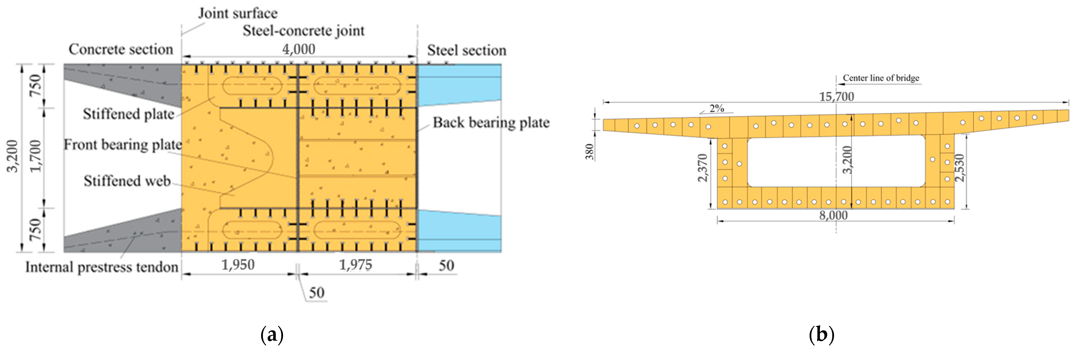
2. Engineering Background

Damaogang Bridge in Shanghai is a three-span steel–concrete hybrid continuous-girder bridge with a span arrangement of (65 + 135 + 65) m. The mid-span of this bridge consists of a 40 m long concrete beam, a 55 m long steel beam, and a 40 m long concrete beam. The steel box girder’s ends are connected to the concrete sections through the steel–concrete joints featuring the front and back bearing plates with cells. In order to ensure the shear force transfer between the concrete beam and steel beam, and to prevent stripping between the steel structure and the concrete structure, welding studs are arranged on the top and bottom plates and bearing plates. Additionally, the perfo-bond connectors embedded in the concrete are employed on the top and bottom plates of the steel box girder. At the same time, steel tendons are connected in the hole, subjecting the concrete within to a three-dimensional compression state, thereby enhancing the shear bearing capacity. The longitudinal internal prestressed steel strand is anchored at one end to the end bearing plate, while the other end is anchored within the concrete. The externally prestressed steel strand passes through the joints and the steel beam, with both ends anchored in the concrete to make the connection between the concrete beam and the steel beam firm. Figure 1 shows the joint structure.

3. Finite Element Model

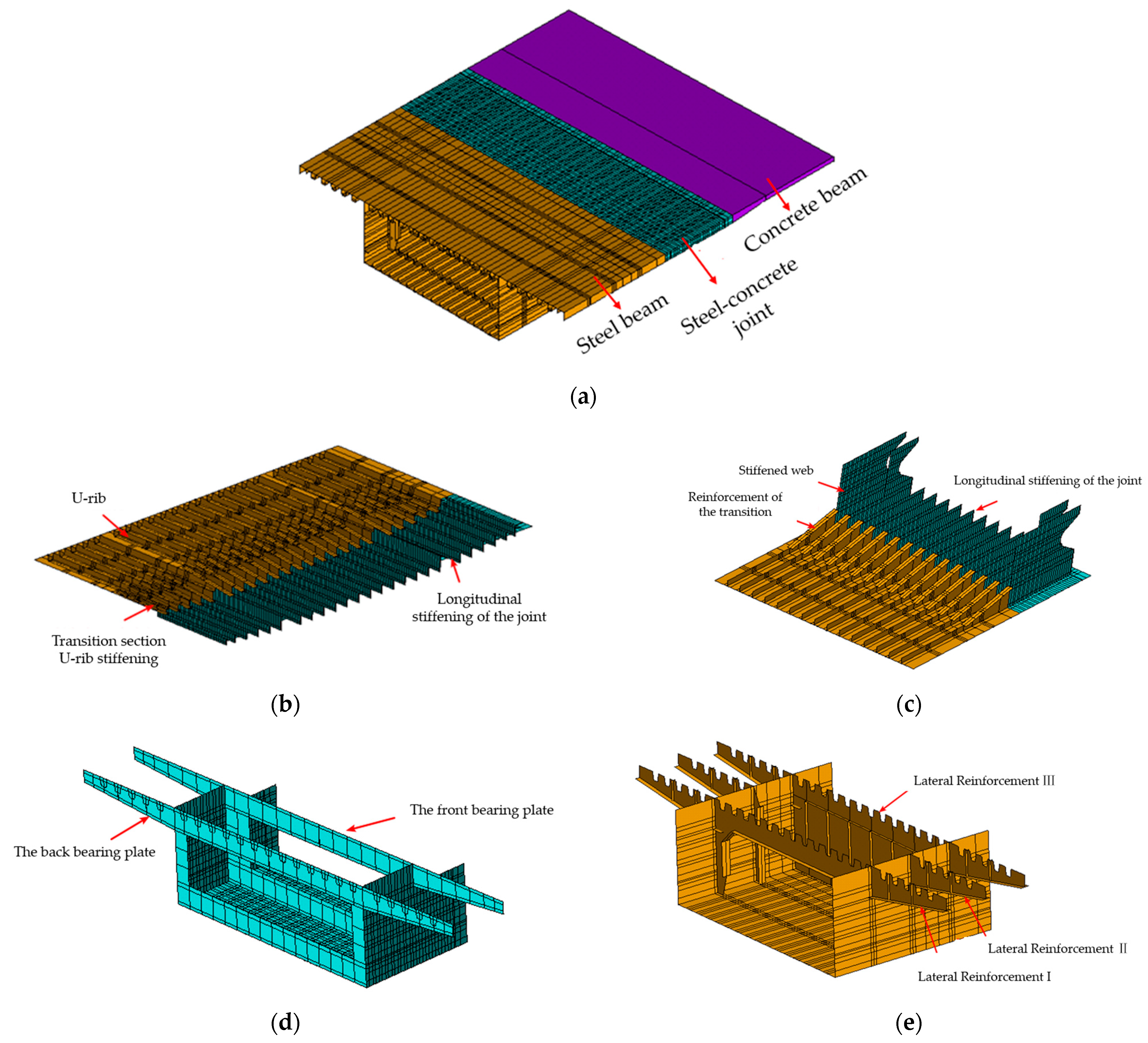
3.1. Establishment of Finite Element Model

To study the reasonable structural parameters and force transmission mechanism of the steel–concrete joint, this paper establishes a refined finite element model of the bridge joint using the ANSYS version 18.2 mechanical software, and verifies the correctness of the model with on-site monitoring data.
The joint of the bridge is located at about one-third of the main span, with relatively small structural internal forces. At the same time, the joint uses thicker steel plates and concrete, and a concrete beam transition section and a steel beam transition section are set at both ends of the joint, resulting in lower stress levels for each component of the joint. Without considering the local stress concentration, it can be considered that the components of the joint have always been in the linear elastic range under load. Therefore, this paper only establishes the linear constitutive relationship of the material during simulation, and the material properties are shown in Table 1. In the model, the tension force of the finely rolled threaded tendon is 568.2 kN, and the controlled tension stress of the longitudinal steel strand is 1395 MPa, taking into account a 20% prestress loss.
In the finite element model, the steel plate is simulated by shell181 elements; the concrete in the joint cell is simulated by solid65 elements; the prestressed tendon is simulated by link8 elements; and the tensioning process of the prestressed tendon is simulated by giving the initial strain to the link8 elements. The linear axial spring element Combin14 is employed to simulate the studs and perfo-bond connectors at the joint. The steel plate element is discretized into quadrilateral grids, while the concrete element is discretized into tetrahedral grids. The structural influence of prestressed tendons is primarily concentrated at the anchorage points, and each prestressed tendon is represented by a single element. The finite element model of the joint is shown in Figure 2.
In the finite element model, the frictional force transmission between the steel structure and the concrete at the joint is ignored. Only the influence of the bearing plates and connecting parts is considered, which provides a certain safety reserve for the calculation results. To account for the high stiffness and small deformation in the concrete section during simulation, the model structure is formed into a single cantilever system by constraining the six-direction freedoms of the nodes at the end section of the concrete beam. A main node is established at the centroid position of the steel beam’s end section, and a constraint equation is employed to connect the main node with other nodes in the section, forming a rigid domain. Based on Midas Civil version 2020, a finite element model of the superstructure of the bridge is established, and the influence line of the positive bending moment of the joint section is calculated and analyzed. Considering the most unfavorable load combination, the influence line of the positive bending moment of the joint section is calculated and analyzed, and the most unfavorable layout of the vehicle load and the internal force of the section are extracted. These internal force values are then applied to the main node as the internal force boundary condition of the refined model, as outlined in Table 2. Under working condition 1, the maximum positive bending moment appears at the B-B section of the joint (at the back bearing plate). Meanwhile, under working condition 2, the maximum positive bending moment appears at the A-A section (at the section where the joint welding studs are located), as shown in Figure 3. The vehicle load and bridge deck pavement load in the finite model are simulated according to the surface uniform load form of 10.5 kN/m and 105 kN/m, respectively.
To mitigate the impact of boundary conditions at both ends of the local model on the stress analysis of the joint, the main concrete beam and main steel beam on both sides are taken as 6 m each, with a joint length of 4 m. The longitudinal extent of the entire local model is 16 m. Figure 4 shows the finite element model of the joint.

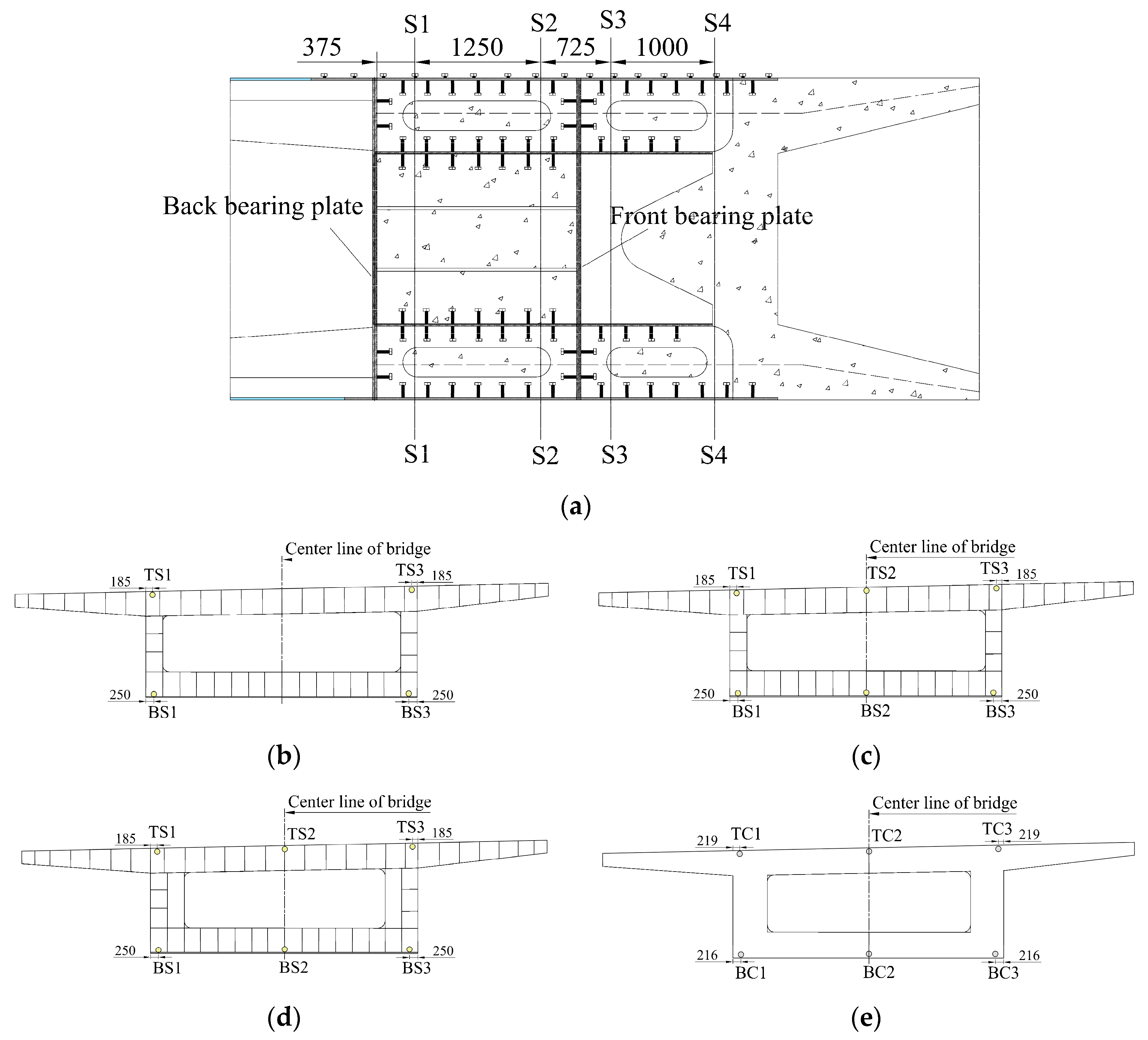
3.2. Verification of Finite Element Model

In order to verify the correctness of the finite element model, the longitudinal stress of the joint under the working condition of prestressed tendon tension at the joint during on-site construction is monitored with a fiber Bragg grating strain sensor. Figure 5 shows the layout of the measurement points. The concrete stress monitoring section adopts embedded strain gauges and is bound to the stressed steel bar. The stress monitoring section of the steel structure is affixed to the top and bottom plates of the steel box and the surface of longitudinal stiffener using surface-mount strain gauges. TS1~TS3 represent the measuring points of the steel structure top plate; BS1~BS3 represent the measuring points in the steel structure bottom plate; TC1~TC3 represent the measuring points in the concrete top plate; BC1~BC3 represent the measuring points in the concrete bottom plate.
Figure 5. (a) Stress monitoring sections (unit: mm); (b) steel structure measuring point arrangement of S1–S1 section (unit: mm); (c) steel structure measuring point arrangement of S2–S2 section (unit: mm); (d) steel structure measuring point arrangements of S3–S3 and S4–S4 sections (unit: mm); (e) concrete structure measuring point arrangements of S3–S3 and S4–S4 sections (unit: mm). Under the working condition of prestressed tendon tension at the joint, the longitudinal stress values were measured and calculated at each designated point, as presented in Table 3 and Table 4. The calculated stress values at the joint are in good agreement with the measured stress values. The maximum error between the calculated stress values of the steel structure and the measured stress values of the steel structure does not exceed 20%, and the maximum error between the calculated stress values of the concrete structure and the measured stress values of the concrete structure does not exceed 15%. This oversight results in a certain safety margin in the calculation results. The reason for the error between the calculated and measured values may be that the model only considers the action of the bearing plates and the connectors, while ignoring the friction transmission between the steel and concrete structures at the joint. This omission leads to a certain safety margin in the calculated results. The above results show that the finite element model is consistent with the actual situation, thereby verifying the model’s accuracy.
Buildings 14 00708 g005

4. Structural Parameter Sensitivity

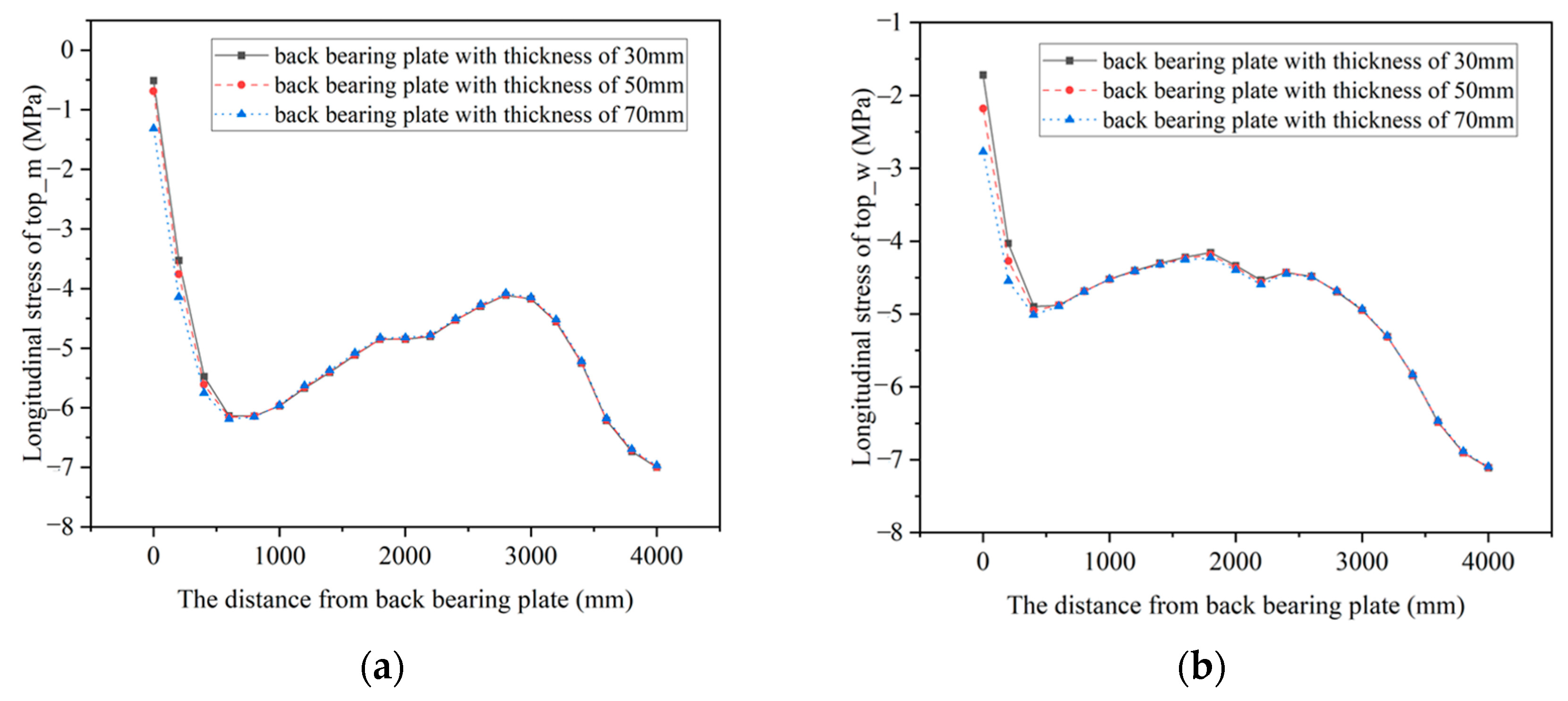
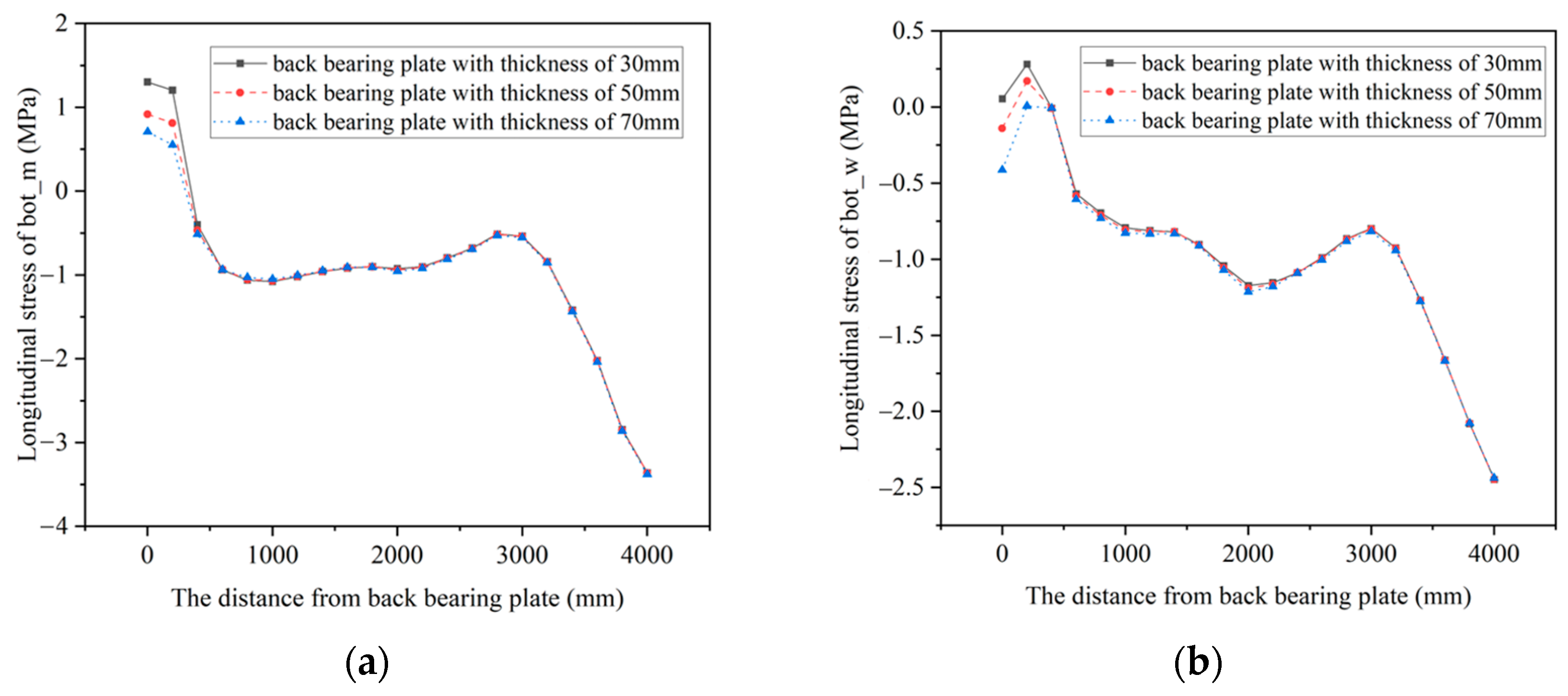
4.1. Thickness of the Back Bearing Plate

To satisfy the stiffness requirements, a larger thickness of the bearing plate is generally selected during design. In the background bridge, the thickness of the bearing plate is 50 mm. In this paper, 30 mm, 50 mm, and 70 mm back bearing plates are selected to establish finite element models and analyze the structural stress characteristics under working condition 1.
The Von Mises stress distributions in the back bearing plates with different thicknesses under working condition 1 are shown in Figure 6. At the welding positions between the back bearing plate and the stiffeners, as well as the anchoring positions of the prestressed tendons, there will be a significant stress concentration. The maximum concentrated stress values of the back bearing plates with different thicknesses are 153.71 MPa, 112.5 MPa, and 83.29 MPa. When the thickness of the back bearing plate increases, the overall level of Mises stress decreases which alleviates the phenomenon of stress concentration, making the stress distribution more uniform.
In the joint, two points at the beam centerline position and web position in the top plate are selected, marked as top_m and top_w, respectively; two points at the beam centerline position and web position in the bottom plate are selected, marked as bot_m and bot_w, respectively, for the joint stress analysis.
Figure 7 and Figure 8 show the longitudinal stress at each point of the steel structures in the joints with different thicknesses of the back bearing plates under working condition 1. Near the back bearing plate, the compressive stress in the steel top plate experiences a slight reduction with increasing thickness of the back bearing plate, but the effect is not significant, while the tensile stress in the steel bottom plate increases with the increase in the back bearing plate thickness. When the back bearing plate thickness changes, the stress in the top and bottom plates only changes near the back bearing plate, and there is almost no change in other positions. The impact range of the back bearing plate thickness on the stress in the steel structure is mainly between 0 mm and 200 mm. This indicates that the influence of the back bearing plate thickness on the steel structure is mainly in the vicinity of the bearing plate, and the thickness of the back bearing plate significantly affects the stress in the steel structure’s bottom plate.
Figure 9 and Figure 10 show the longitudinal stress at each point in the concrete structures within the joints with different thicknesses of the back bearing plates under working condition 1. The results show that the influence range of the back bearing plate thickness on concrete stress is mainly between 0 mm and 400 mm. Within this range, the compressive in of the concrete top plate demonstrates an increase with the augmentation of the back bearing plate thickness, while the tensile stress in the concrete bottom plate decreases with the increase in the back bearing plate thickness. When the back bearing plate thickness increases, the pressure transmitted from the back bearing plate to the concrete structure will increase, and the stress distribution within the concrete structure will be more uniform.
The change in the thickness of the back bearing plate can affect the stress distribution near the back bearing plate of the joint. For the steel structure, the stress levels and changes in stress caused by the change in the thickness of the back bearing plate are relatively small compared to the allowable stress of the steel structure, but a thicker back bearing plate can alleviate the stress concentration phenomenon, making the Mises stress distribution more uniform and the overall stress level in the back bearing plate decrease; for the concrete structure, the increase in the back bearing plate thickness can reduce the tensile stress near the back bearing plate. Therefore, a range of 50 mm~70 mm is suggested for the thickness of the back bearing plate.

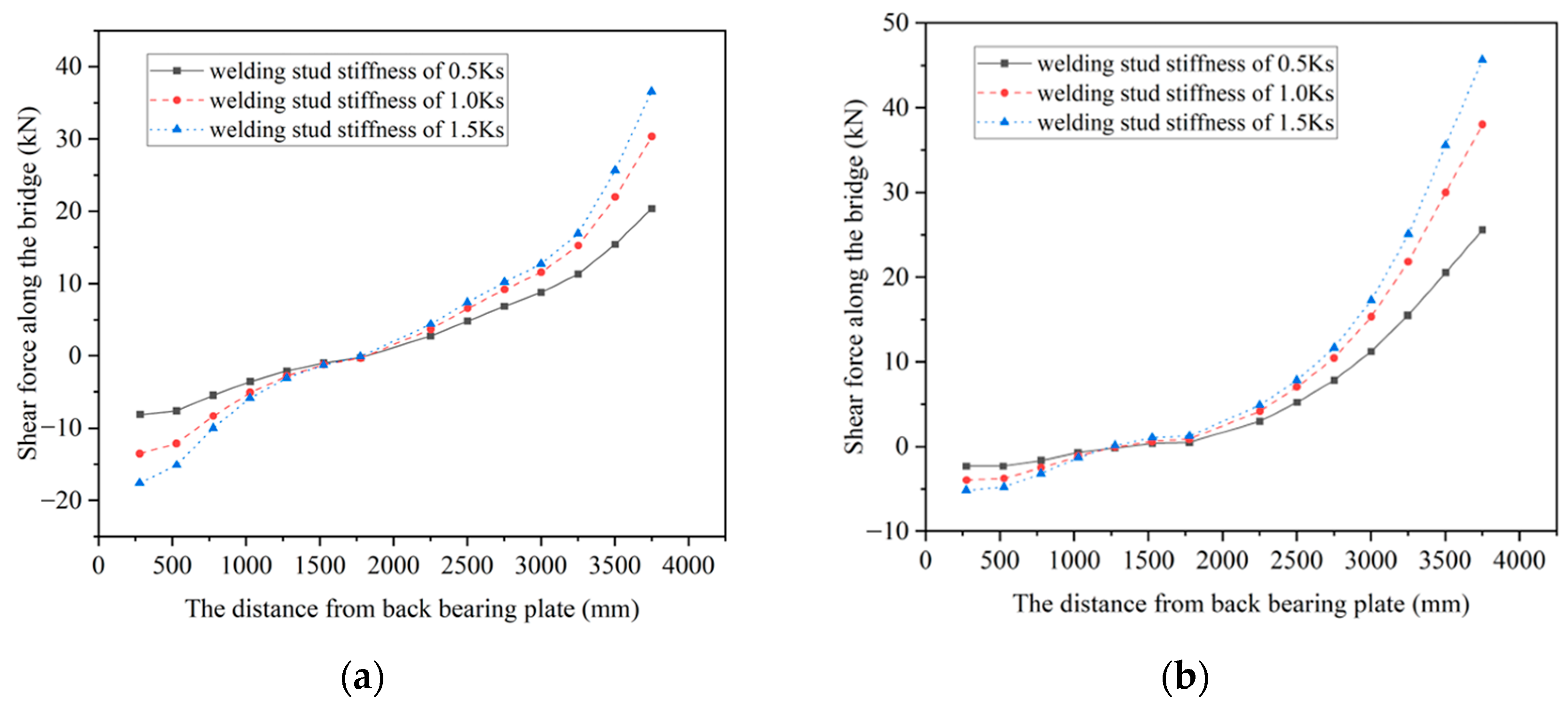
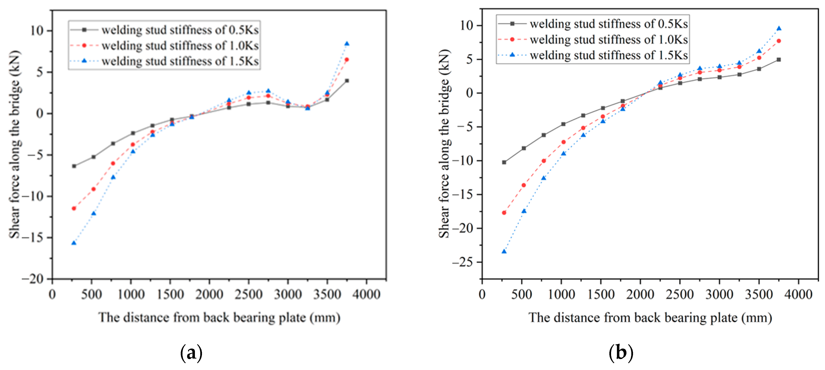
4.2. Stiffness of the Welding Studs

Based on the stiffness of the welding studs in the background bridge, the stiffness is reduced by 0.5 times, kept constant, and increased by 0.5 times. The welding studs with different stiffnesses are represented by 0.5 Ks, 1.0 Ks, and 1.5 Ks, as shown in Table 5. The influence of the stiffness of the welding studs on the shear force of the top and bottom plate welding studs is studied.
Along the longitudinal direction of the bridge, fourteen rows of welding studs are arranged on the top and bottom plates of the steel structure, extending from the section of the back bearing plate to the steel–concrete joint surface. The welding studs near the centerline of the bridge and web were selected to investigate the impact of the welding studs’ stiffness on the shear force along the bridge direction of the top and bottom studs under working condition 2.
Under working condition 2, the distribution of shear forces along the bridge direction of the top and bottom plate welding studs in the joints with different stiffness welding studs is shown in Figure 11 and Figure 12, where a positive shear force represents the relative displacement of concrete and steel units in opposite directions, and a negative shear force represents the relative displacement of the two in backward directions.
For the top plate, the distribution of stud shear forces near the web and the centerline of the bridge is consistent, as is shown in Figure 11. On the whole, with the increase in the welding studs’ stiffness, the shear forces along the bridge direction of the welding studs in the same position increase. The closer the position is to the back bearing plate or the steel–concrete joint surface, the more clearly the shear force increases. In addition, with the increase in the welding studs’ stiffness, the change rate of the shear force along the bridge direction of the top plate welding studs also increases. The results indicate that the increase in the stiffness of the welding studs leads to a larger range of shear forces along the bridge direction of the top plate welding studs, and the longitudinal distribution of shear forces along the bridge direction of the top plate welding studs also becomes more uneven.
For the bottom plate, there is a peak shear force in the stud near the centerline of the bridge between the front bearing plate and the steel–concrete joint surface. In contrast, the longitudinal distribution of the studs’ shear forces near the web does not show this characteristic; but on the whole, there is consistency in the stud shear forces near the web and the centerline of the bridge, as is shown in Figure 12. With the increase in the studs’ stiffness, the shear forces of the studs in the same position increase, which is most significant near the back bearing plate and the steel–concrete joint surface. In addition, with the increase in the studs’ stiffness, the change rate of shear force along the bridge direction of the top plate welding studs also increases. The results indicate that the increase in the stiffness of the welding studs leads to a larger range of shear forces along the bridge direction of the bottom plate welding studs, and the longitudinal distribution of shear forces along the bridge direction of the top plate welding studs also becomes more uneven.
The influence of changes in welding stud stiffness on the shear force of the top and bottom plate welding studs is mainly manifested in the change in the shear force values and the change in the shear force distribution. With the increase in the welding studs’ stiffness, the maximum shear force of the top and bottom plate welding studs increases, and the longitudinal distribution of the shear forces of the welding studs becomes more uneven. This non-uniform distribution can lead to an excessive localized force in the process of force transmission at the joint. To make the forces within the welding studs more uniform, enhance the overall utilization efficiency of the welding studs, and prevent damage caused by excessive forces within the welding studs, the stiffness of the welding studs should not be too large on the basis of ensuring the safety of the joint connection.

5. Force Transmission Mechanism

To investigate the force transmission mechanism of the joint, nine sections were strategically chosen, ranging from the back bearing plate section to the joint surface, with a consistent spacing of 0.5 m. Based on working condition 1, the internal force bearing ratios of both the steel and concrete structures in the joint of the background bridge are calculated, as shown in Figure 13.
In the section proximate to the rear bearing plate, 61% of the bending moment, 79% of the axial force, and 55% of the shear force are borne by the concrete structure, while the remaining internal forces are borne by the steel structure. With the increase in section distance, the ratio of the bending moment borne by the concrete structure steadily rise; the ratio of axial force borne by the concrete structure exhibits an initial decrease followed by an increase; the ratio of shear force borne by the concrete structure increases uniformly. The results indicate that the internal force bearing ratio of the concrete structure is higher than that of the steel structure in the joint, and the concrete near the joint surface will bear all the internal forces.
The steel beam section first disperses stress to components such as the top and bottom plates, web plates, and stiffeners through the transition section of the steel beam, resulting in stress reduction. The normal stress generated by axial force and bending moment is transferred from the steel structure to the concrete structure through the contact-bearing way of the rear bearing plate, which is the main way of transferring the normal stress in the joint with a short force path and high efficiency. The remaining normal stress is transmitted to the concrete structure by shearing through the connectors on the top and bottom plates, web plates, and perforated plates, which is an indirect force transfer method, extending the force transfer path and increasing the force transfer area. The combination of bearing and shearing at the joint facilitates the transfer of normal stress from the steel beam section to the concrete beam section.

6. Conclusions

In this research, a finite element model of the joints in a bridge is established to investigate the influence of the bearing plate thickness and welding studs stiffness on the mechanical behavior of the joint and to analyze the force transmission mechanism of the joint. The main conclusions are as follows:
  • The stress values calculated at the joint are in good agreement with the measured stress values, in which the maximum error between the calculated and measured values of the steel structure does not exceed 20%; the maximum error between the calculated and measured values of the concrete structure does not exceed 15%. Neglecting the frictional force transmission between the steel structure and the concrete at the joint results in a certain safety reserve for the calculation results;
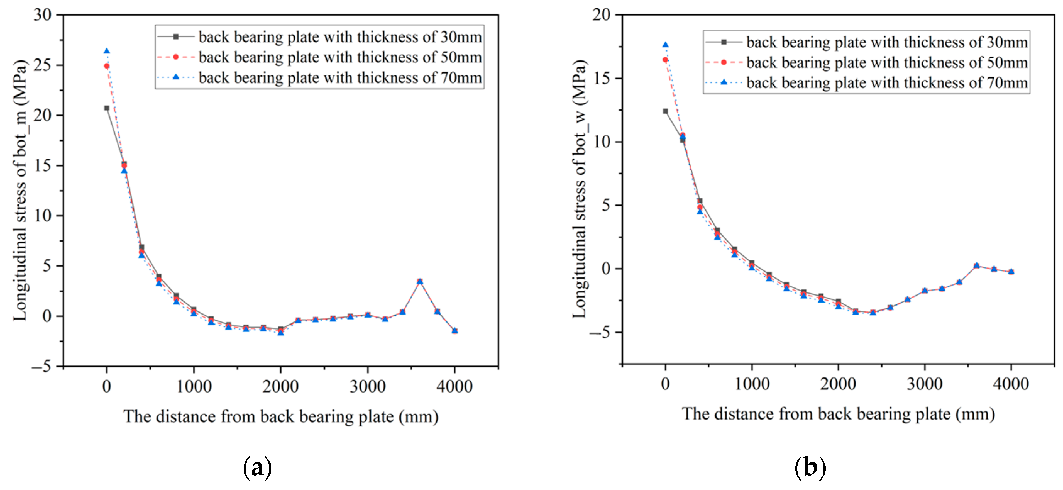
  • The use of a thicker back bearing plate can alleviate the stress concentration phenomenon at the welding positions between the back bearing plate and the stiffeners, as well as at the anchoring positions of the prestressed tendons, making the Mises stress distribution more uniform and the overall stress level decrease. The change in the bearing plate thickness has a large impact on the stresses within the steel structure and the concrete in the proximity of the bearing plate. For the steel structure near the back bearing plate, the compressive stress of the steel top plate decreases with an increase in the back bearing plate’s thickness, while the tensile stress in the steel bottom plate escalates correspondingly, and the opposite is true for the concrete structures. The influence range of the back bearing plate thickness on concrete stress is mainly between 0 mm and 400 mm. It is recommended to maintain a back bearing plate thickness within the range of 50 mm~70 mm;
  • Reducing the stiffness of the welding studs by 0.5 times, keeping it the same, or increasing it by 0.5 times shows that an increase in the welding studs’ stiffness makes the range of the shear force along the bridge direction of the top and bottom welding studs larger, and the longitudinal distribution of the welding studs’ shear force is more uneven. To avoid the damage caused by the excessive forces of the welding studs, the stiffness of the welding studs should not be too large on the basis of ensuring the safety of the joint connection;
  • The internal force bearing ratio of the concrete structure is higher than that of the steel structure in the joint. The transmission of normal stress at the junction occurs from the steel beam section to the concrete beam section through two ways: bearing and shearing. Notably, the primary mode of force transmission for normal stress involves contact bearing through the back bearing plate.

Author Contributions

Conceptualization, L.J.; methodology, L.J. and S.Y.; formal analysis, L.J., H.P., J.L., S.Y., T.W. and G.Z.; investigation, H.P. and J.L.; Data curation, J.L., S.Y., T.W. and G.Z.; writing—original draft preparation, S.Y. and L.J.; writing—review and editing, H.P., S.Y., T.W. and G.Z.; supervision, L.J. and H.P.; project administration, H.P. All authors have read and agreed to the published version of the manuscript.

Funding

This work was supported by the National Natural Science Foundation of China (51878488), Department of Transportation of Jiangxi Province (2022H0019) and Department of Transportation of Jiangxi Province (2023H0008).

Data Availability Statement

The data from this study are available from the corresponding author upon reasonable request.

Acknowledgments

The authors sincerely thank the people who provided assistance during the writing and publication process of the paper.

Conflicts of Interest

Authors Tingying Wu and Huiteng Pei were employed by Jiangxi Communications Design and Research Institute Limited Company. Author Gangyi Zhan was employed by China Railway Shanghai Design Institute Group Limited Company. The authors declare that the research was conducted in the absence of any commercial or financial relationships that could be construed as a potential conflict of interest.

References

  1. Yepes, V.; Dasí-Gil, M.; Martínez-Muñoz, D.; López-Desfilis, V.J.; Martí, J.V. Heuristic Techniques for the Design of Steel-Concrete Composite Pedestrian Bridges. Appl. Sci. 2019, 9, 3253. [Google Scholar] [CrossRef]
  2. Gara, F.; Carbonari, S.; Leoni, G.; Dezi, L. Finite Elements for Higher Order Steel–Concrete Composite Beams. Appl. Sci. 2021, 11, 568. [Google Scholar] [CrossRef]
  3. Lei, Q.; Wang, P.; Nan, H. Study on Mechanical Properties of Simply-Supported Composite Beams Considering Creep and Slip. Appl. Sci. 2022, 13, 193. [Google Scholar] [CrossRef]
  4. Brunesi, E.; Peloso, S.; Pinho, R.; Nascimbene, R. Cyclic testing and analysis of a full-scale cast-in-place reinforced concrete wall-slab-wall structure. Bull. Earthq. Eng. 2018, 16, 5309–5339. [Google Scholar] [CrossRef]
  5. Tang, L.; Wu, W.; Liu, G.; Xu, G. Structural performance of rear bearing-plate connection with cells in steel-concrete hybrid girder. Eng. Mech. 2010, 27, 234–243. [Google Scholar]
  6. Zhang, D.L.; Bao, Y.W.; Gao, J.H.; Xiao, L.; Li, X.Z. Research on load transfer mechanism of steel-concrete joint section of hybrid beam cable-stayed bridge. Adv. Mater. Res. 2013, 639–640, 216–219. [Google Scholar] [CrossRef]
  7. Xing, B.; Li, X.Z. The numerical simulation analysis method of steel-concrete joint section in hybrid girder of cable-stayed bridge. Adv. Mater. Res. 2014, 1049–1050, 226–233. [Google Scholar] [CrossRef]
  8. Zhang, G.; Chen, C.; Liu, Y. Load transfer mechanism between cells and bearing-plate in hybrid girder joint. J. Tongji Univ. Nat. Sci. 2017, 45, 658–663. [Google Scholar]
  9. He, S.; Mosallam, A.S.; Fang, Z.; Liu, L. Structural evaluation of steel–concrete joint with uhpc grout in single cable–plane hybrid cable-stayed bridges. J. Bridge Eng. 2019, 24, 04019022. [Google Scholar] [CrossRef]
  10. Yang, S.; Pu, Q.; Shi, Z.; Hong, Y. Mechanical behavior of steel–concrete composite joints in railway hybrid cable-stayed bridges. J. Constr. Steel Res. 2020, 173, 106242. [Google Scholar] [CrossRef]
  11. Pu, Q.; Yang, S.; Shi, Z.; Hong, Y.; Zhou, Y. Fatigue performance of an innovative steel–concrete joint in long-span railway hybrid box girder cable-stayed bridges. J. Bridge Eng. 2021, 26, 04020129. [Google Scholar] [CrossRef]
  12. Gu, Y.-W.; Nie, X.; Liu, Y.-F.; Duan, S.-K.; Fan, J.-S. Experimental and numerical study of steel-to-concrete joint section in hybrid cable-stayed bridges. J. Constr. Steel Res. 2021, 187, 106982. [Google Scholar] [CrossRef]
  13. Yao, Y.; Yan, M.; Shi, Z.; Wang, Y.; Bao, Y. Mechanical behavior of an innovative steel–concrete joint for long-span railway hybrid box girder cable-stayed bridges. Eng. Struct. 2021, 239, 112358. [Google Scholar] [CrossRef]
  14. Xu, C.; Zhang, L.; Su, Q.; Abbas, S. Mechanical behavior of a novel steel–concrete joint in concrete-composited hybrid continuous bridges. Structures 2022, 36, 291–302. [Google Scholar] [CrossRef]
  15. Zhou, Y.; Pu, Q.; Shi, Z.; Gou, H.; Chen, X. Experimental and numerical parametric study of the mechanical properties in a steel–concrete joint section. Int. J. Civ. Eng. 2022, 20, 1431–1446. [Google Scholar] [CrossRef]
  16. Liang, H.; Tan, K.; Deng, K.; Zhang, Y.; Zhao, C.; Yang, T. Crack resistance of steel–concrete hybrid joint between concrete girder and steel–concrete composite girder in long-span cable-stayed bridge under hogging moment. J. Bridge Eng. 2023, 28, 05022013. [Google Scholar] [CrossRef]
  17. He, J.; Liu, Y.; Pei, B. Experimental study of the steel-concrete connection in hybrid cable-stayed bridges. J. Perform. Constr. Facil. 2014, 28, 559–570. [Google Scholar] [CrossRef]
  18. He, S.; Fang, Z.; Fang, Y.; Liu, M.; Liu, L.; Mosallam, A.S. Experimental study on perfobond strip connector in steel–concrete joints of hybrid bridges. J. Constr. Steel Res. 2016, 118, 169–179. [Google Scholar] [CrossRef]
  19. Di, J.; Zou, Y.; Zhou, X.; Qin, F.; Peng, X. Push-out test of large perfobond connectors in steel–concrete joints of hybrid bridges. J. Constr. Steel Res. 2018, 150, 415–429. [Google Scholar] [CrossRef]
  20. Zou, Y.; Di, J.; Zhou, J.; Zhang, Z.; Li, X.; Zhang, H.; Qin, F. Shear behavior of perfobond connectors in the steel-concrete joints of hybrid bridges. J. Constr. Steel Res. 2020, 172, 106217. [Google Scholar] [CrossRef]
  21. Zou, Y.; Zheng, K.; Zhou, J.; Zhang, Z.; Li, X. Mechanical behavior of perfobond connector group in steel–concrete joint of hybrid bridge. Structures 2021, 30, 925–936. [Google Scholar] [CrossRef]
  22. Zhou, Y.; Pu, Q.-H.; Shi, Z.; Gou, H.-Y.; Yang, S.-L. Experimental study on fatigue performance of steel-concrete joint section of hybrid girder cable-stayed bridge. Adv. Steel Constr. 2022, 18, 536–543. [Google Scholar] [CrossRef]
  23. Zhao, L.; Sun, C.; Yang, X. Stability analysis of edong yangtze river bridge during construction. J. Southwest Jiaotong Univ. 2012, 47, 741–747. [Google Scholar]
  24. He, Z.-Q.; Chen, J.; Liu, Z.; Ma, Z.J. An explicit approach for determining the rational length of steel portion in steel–concrete hybrid girder bridges. J. Bridge Eng. 2023, 28, 05022011. [Google Scholar] [CrossRef]
  25. Liu, M. Practices and prospects of steel-concrete composite technology in bridge engineering. Bridge Constr. 2022, 52, 18–25. [Google Scholar]
Figure 1. (a) Longitudinal section of joint (unit: mm); (b) cross section of joint (unit: mm).
Buildings 14 00708 g001
Figure 2. The finite element model of a joint. (a) The fine finite element model of the joint; (b) top plate stiffened longitudinally; (c) bottom plate lengthwise stiffened and stiffened web; (d) joint bearing plate; (e) steel beam section transverse partition.
Buildings 14 00708 g002
Figure 3. The most unfavorable sections of positive bending moment under two working conditions.
Buildings 14 00708 g003
Figure 4. The finite element model’s boundary conditions.
Buildings 14 00708 g004
Figure 6. (a) The Mises stress in the back bearing plate when t = 30 mm (unit: MPa); (b) the Mises stress in the back bearing plate when t = 50 mm (unit: MPa); (c) the Mises stress in the back bearing plate when t = 70 mm (unit: MPa).
Buildings 14 00708 g006
Figure 7. The longitudinal stress in a steel top plate. (a) The longitudinal stress at top_m; (b) The longitudinal stress at top_w.
Buildings 14 00708 g007
Figure 8. The longitudinal stress in steel bottom plate. (a) The longitudinal stress at bot_m; (b) The longitudinal stress at bot_w.
Buildings 14 00708 g008
Figure 9. The longitudinal stress in concrete top plate. (a) The longitudinal stress at top_m; (b) The longitudinal stress at top_w.
Buildings 14 00708 g009
Figure 10. The longitudinal stress in concrete bottom plate. (a) The longitudinal stress at bot_m; (b) The longitudinal stress at bot_w.
Buildings 14 00708 g010
Figure 11. The shear force along the bridge of the top plate welding studs. (a) The shear force of welding studs near the centerline of the bridge; (b) the shear force of welding studs near the web.
Buildings 14 00708 g011
Figure 12. The shear force along the bridge of the bottom plate welding studs. (a) The shear force of welding studs near the centerline of the bridge; (b) the shear force of welding studs near the web.
Buildings 14 00708 g012
Figure 13. The internal force bearing ratios of the steel structure and concrete structure. (a) The bending moment bearing ratio; (b) the axial force bearing ratio; (c) the shear force bearing ratio.
Buildings 14 00708 g013
Table 1. Material/component properties.
Material/ComponentElastic Modulus (104 MPa)Poisson’s RatioVolume Weight (kN/m3)
concrete3.550.226
steel20.60.378.5
vertical prestressed tendon20.0/78.5
longitudinal prestressed steel strand19.5/78.5
Table 2. Internal force boundary conditions.
Loading CaseBending Moment (kN·m)Axial Force
(kN)
Shearing Force
(kN)
working condition 175,162.6−8930.8−2890.1
working condition 272,647.8−8921.5−2763.2
Table 3. Monitoring point longitudinal stress in steel structure top and bottom plates (MPa).
SectionPointMeasured ValueCalculated Value
S1–S1TS1−7.65−8.60
TS3−7.81−8.03
BS1−5.13−4.22
BS3−4.82−4.16
S2–S2TS1−14.01−13.12
TS2−17.24−18.09
TS3−11.31−12.79
BS1−12.98−13.74
BS2−17.35−17.83
BS3−13.89−13.50
S3–S3TS1−10.21−9.61
TS2−12.54−11.78
TS3−8.54−9.37
BS1−12.32−11.41
BS2−11.85−12.16
BS3−11.84−11.15
S4–S4TS1−4.54−5.01
TS2−4.24−4.80
TS3−5.33−4.96
BS1−5.88−5.48
BS2−5.23−5.54
BS3−5.56−5.38
Table 4. Monitoring point longitudinal stress in concrete structure top and bottom plates (MPa).
SectionPointMeasured ValueCalculated Value
S3–S3TC1−2.18−2.42
TC2−2.68−2.94
TC3−2.54−2.38
BC1−3.25−3.39
BC2−2.98−2.86
BC3−3.41−3.32
S4–S4TC1−2.87−3.13
TC2−3.35−3.13
TC3−2.84−3.03
BC1−3.84−3.98
BC2−3.75−3.65
BC3−3.79−3.92
Table 5. Stiffness of the welding studs.
Welding Stud NumberShear Stiffness (kN/mm)Tensile Stiffness (kN/mm)
0.5 Ks180122.5
1.0 Ks360 245
1.5 Ks540367.5
Disclaimer/Publisher’s Note: The statements, opinions and data contained in all publications are solely those of the individual author(s) and contributor(s) and not of MDPI and/or the editor(s). MDPI and/or the editor(s) disclaim responsibility for any injury to people or property resulting from any ideas, methods, instructions or products referred to in the content.

