
Preliminary Geospatial and In Situ Reconnaissance of the 8 September 2023 Moroccan Atlas Earthquake Damage
 , , and
Abstract
1. Introduction
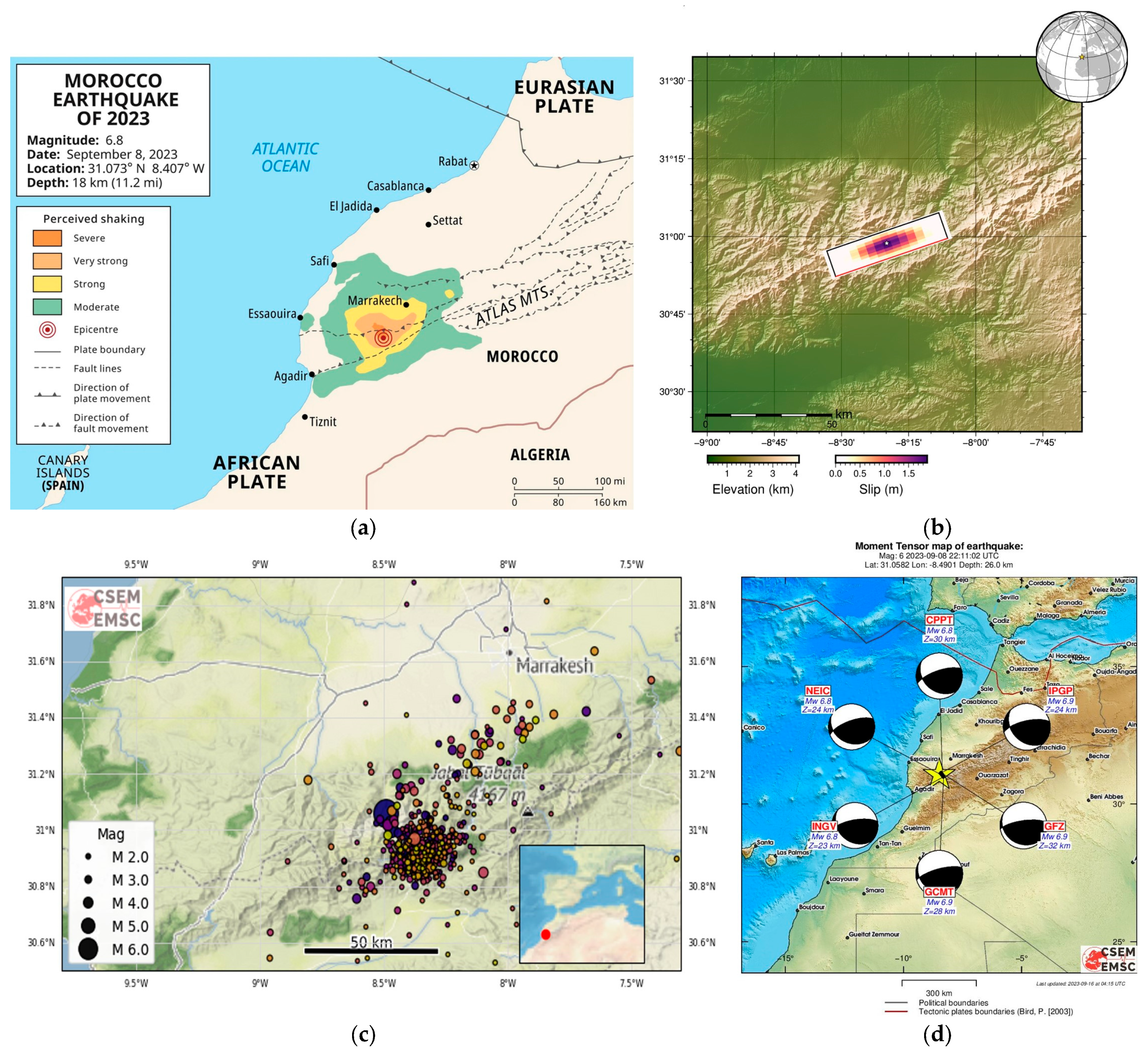
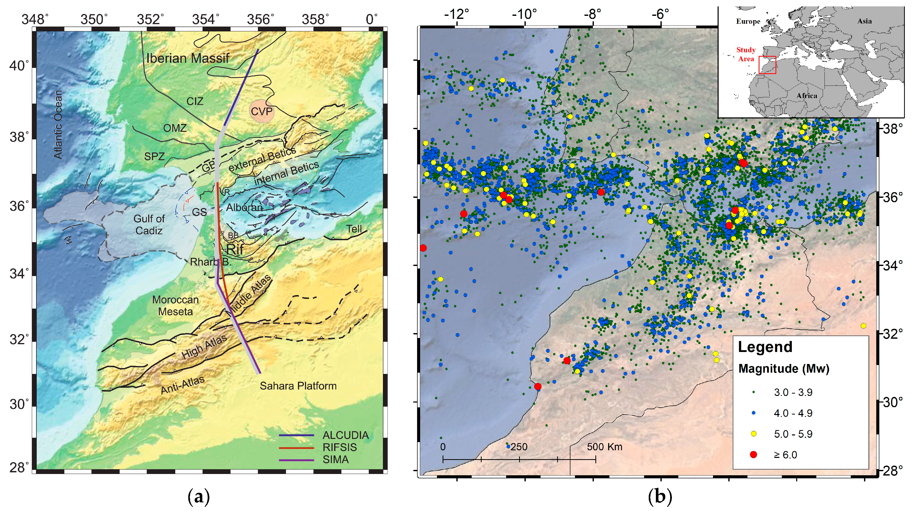
2. Seismotectonic Context
- (1)
- The Atlas domain, where the seismic activity is mainly located in the Middle Atlas and the Central High Atlas. This seismicity is due in large part to the presence of a complex network of active faults. The South Atlas Fault, which starts from Agadir and passes close to Figuig, is marked by violent earthquakes such as that of Agadir (1960, Mw = 5.9). Although the latter was an earthquake of less than magnitude 6, it was the most devastating to occur in Morocco, striking the coastal region near Agadir and claiming approximately 15,000 lives.
- (2)
- Betic–Rif domain: the area between south-eastern Spain to the north and the Rif belt to the south is an intense location where the seismic activity highlights the convergence and collision of the African and Eurasia tectonic plates. This convergence is marked by severe earthquakes in southeastern Spain, in the Alboran Sea and northern Morocco, such as the recent earthquakes in Al Hoceima of 2004 (Mw 6.3) and 2016 (Mw 6.2).
- (3)
- The Atlantic domain: where the boundary between the two plates, represented by the Azores Gibraltar Sicily seismic line, can be clearly distinguished. This is punctuated by earthquakes of magnitude 6 or greater. Moreover, these oceanic earthquakes, particularly those located SW of Cape St Vincent, affect the Iberian Peninsula and Morocco, as was the case in the earthquakes of 1755 (M ≈ 8.5) and 1969 (Ms = 7.3), which largely affected northern Morocco.
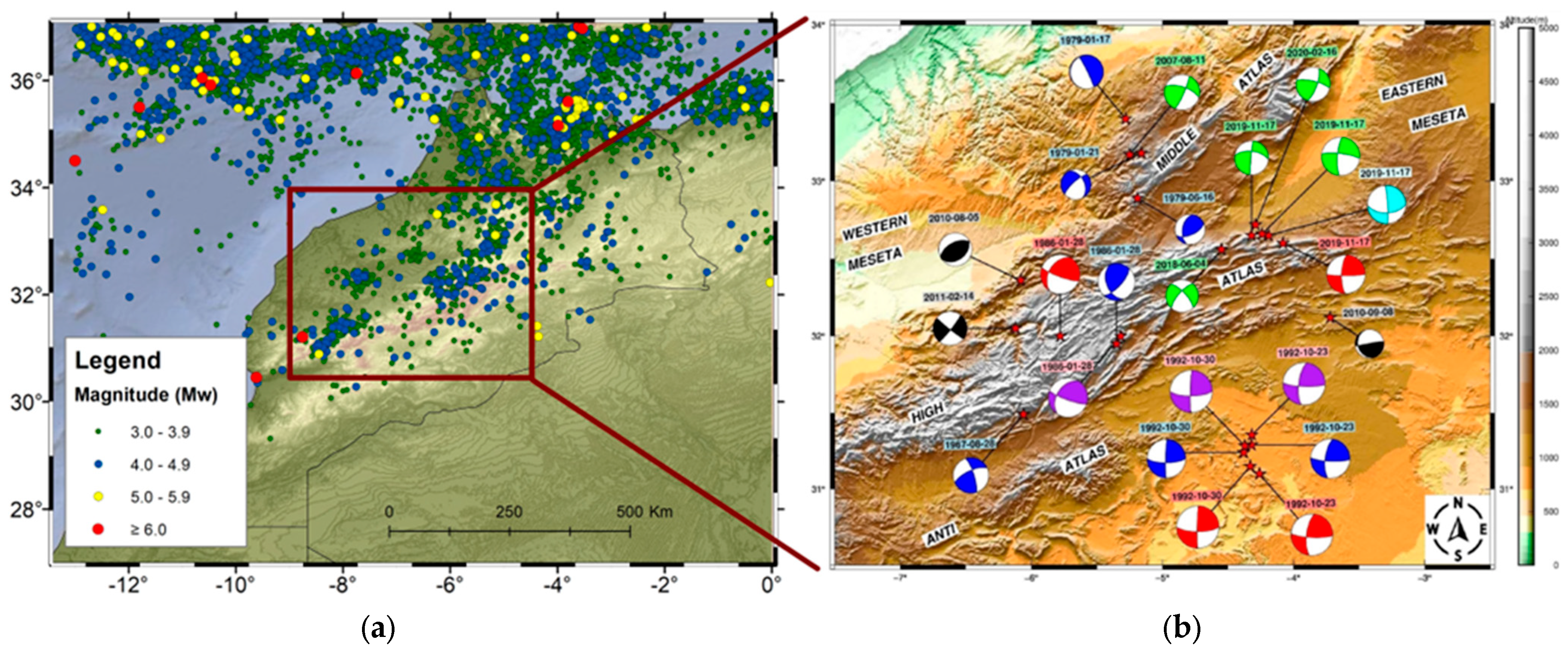
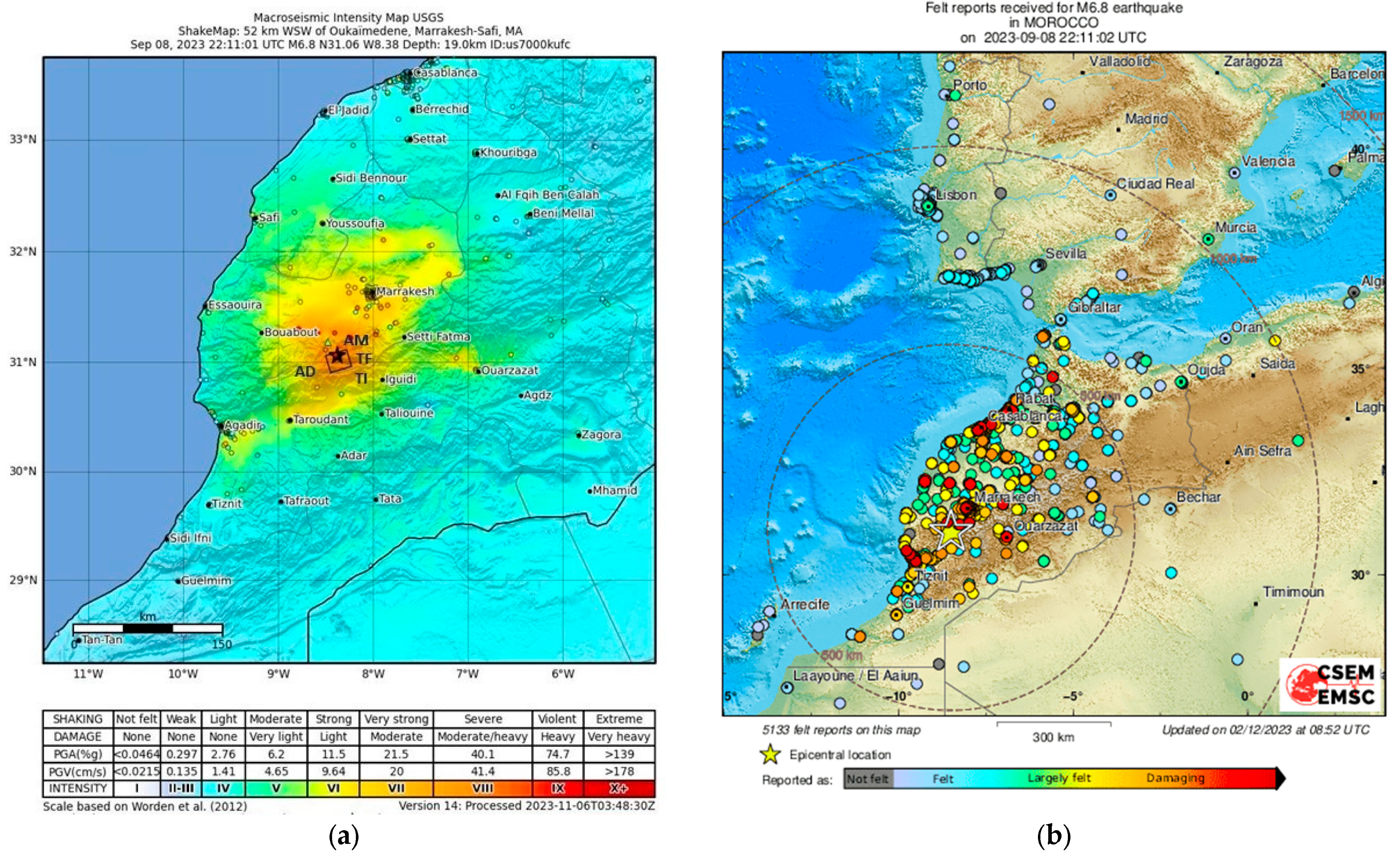
Local Tectonic and Characteristics of the 8 September 2023 Event
3. Building Typology in the Affected Area
Vulnerability of Construction Systems Analysed in the Moroccan Atlas
4. Methodology for Field Campaign Conducted in the High Atlas of Morocco
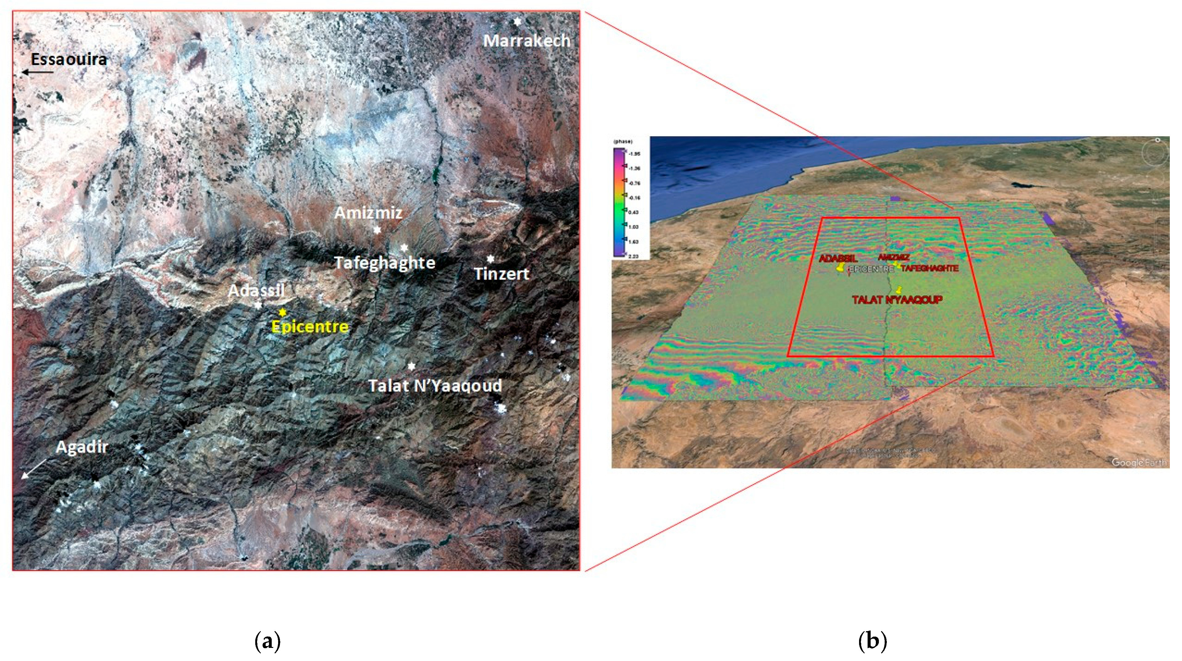
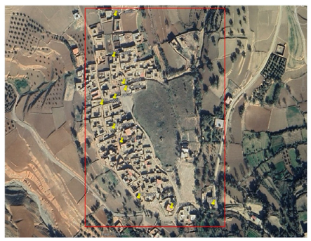
4.1. Selection of the Study Area
4.2. Field Campaign Planning: Geospatial Images and Pre-Processing
4.3. Exploratory Geospatial Analysis
5. Data Collection in the Field
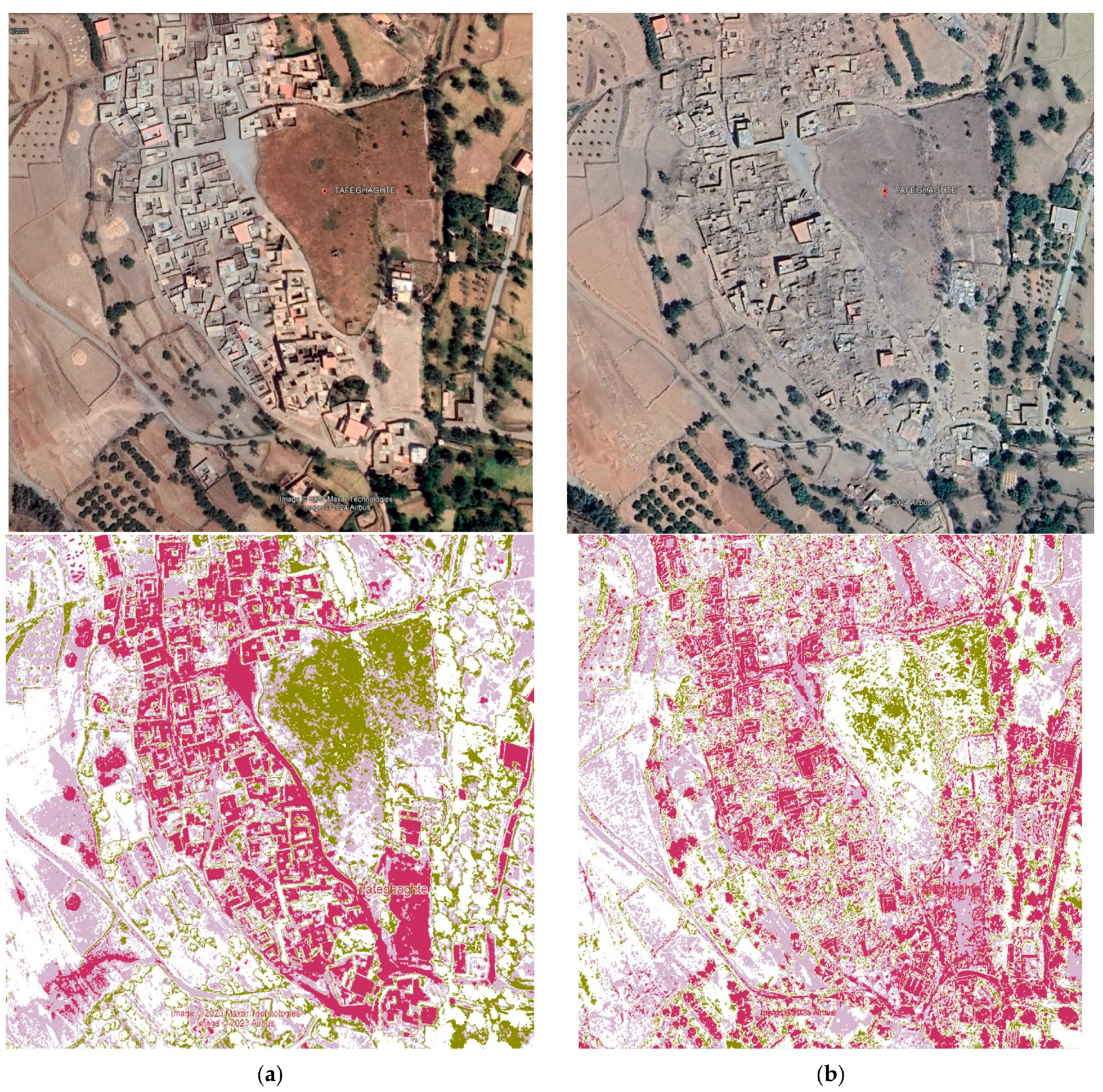
5.1. Post-Processing of Geospatial Images Following Field Campaign
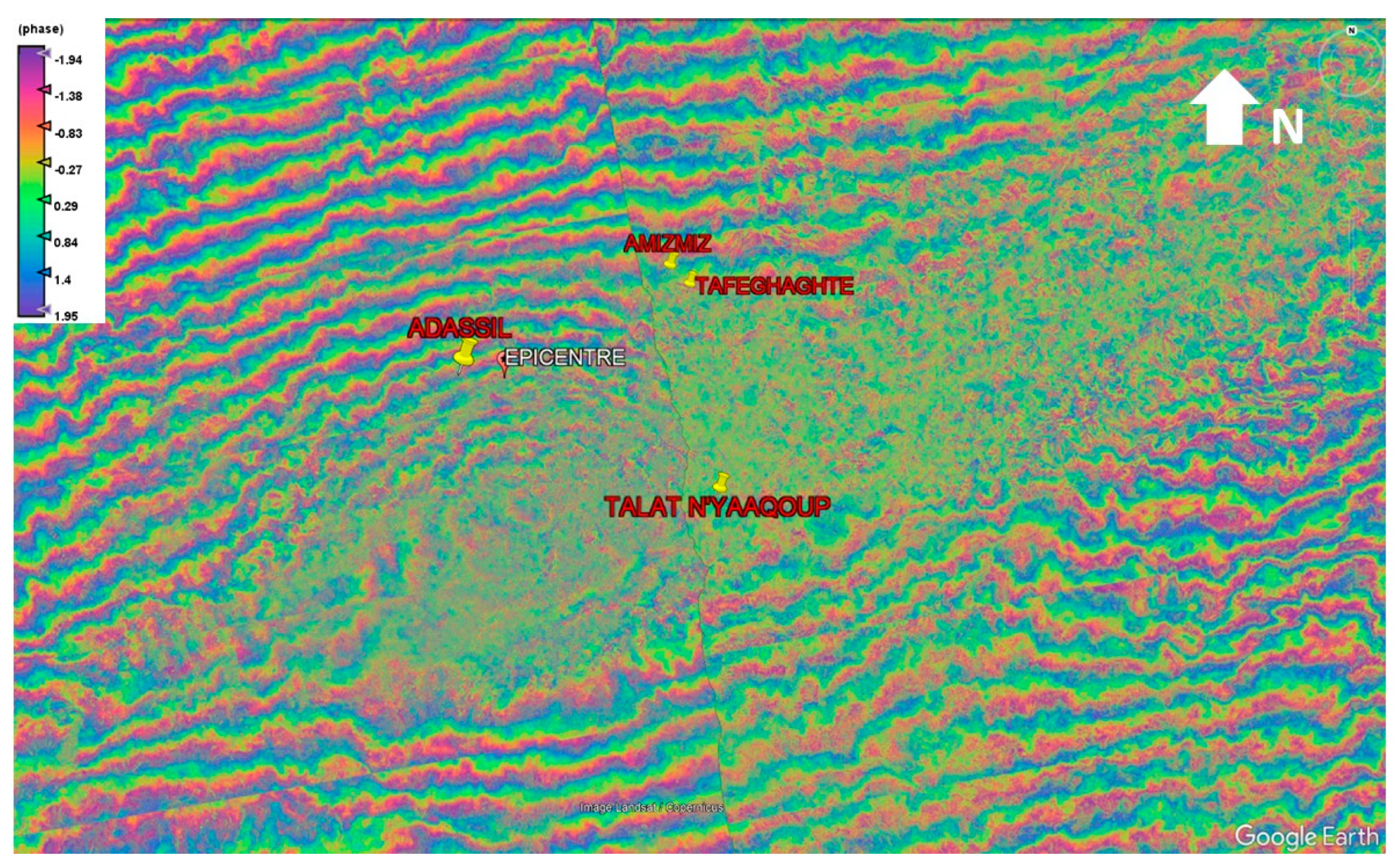
Differential Interferometric Synthetic Radar (DInSAR) Approach
5.2. Construction Characteristics and Observed Damage in Identified Building Systems
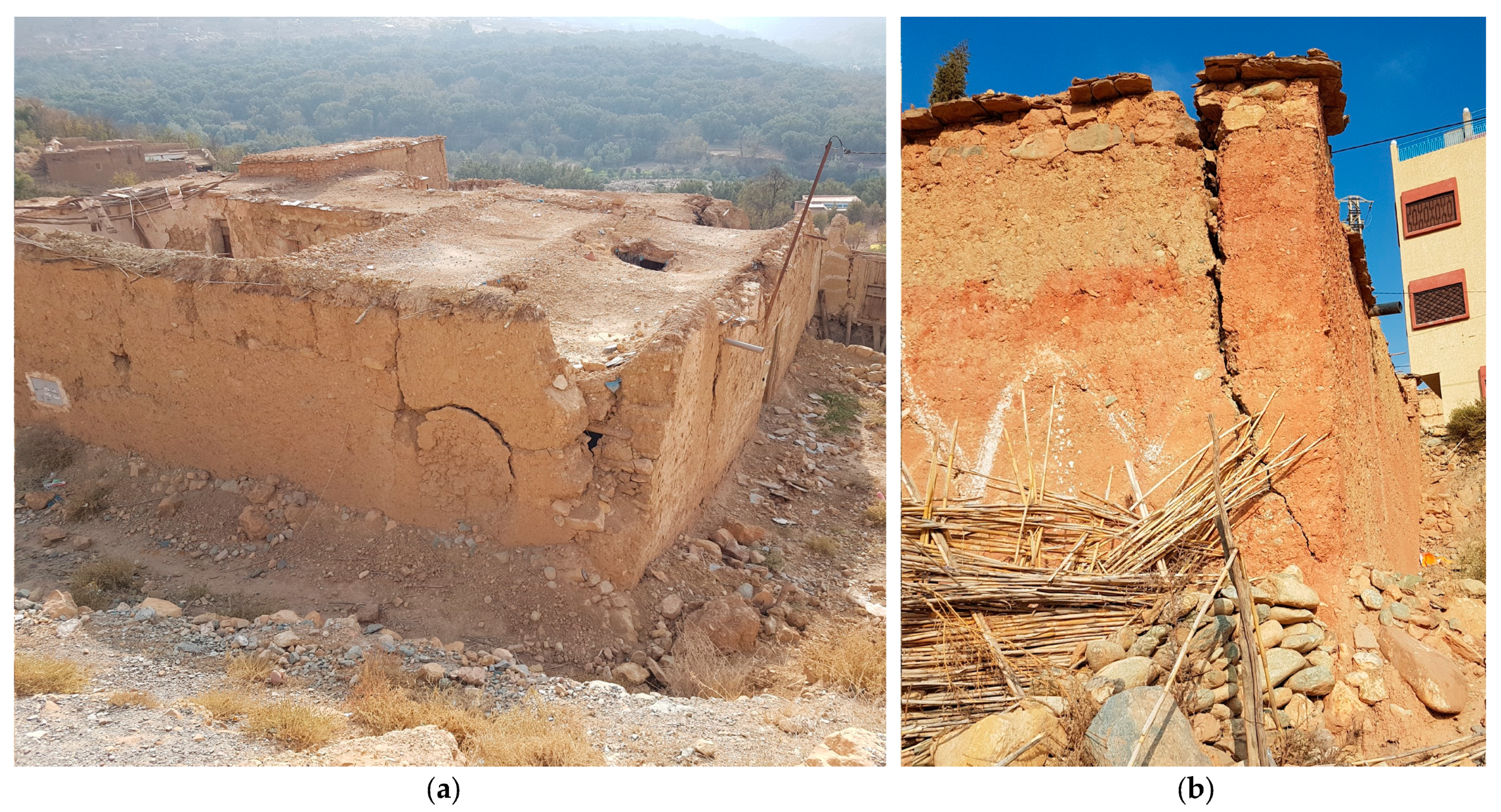
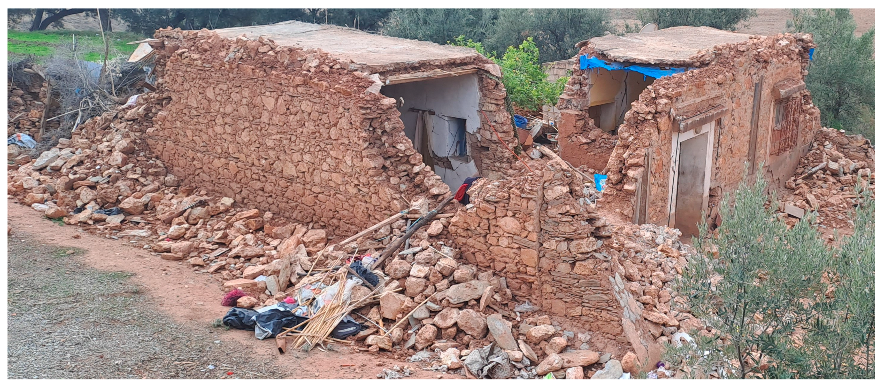
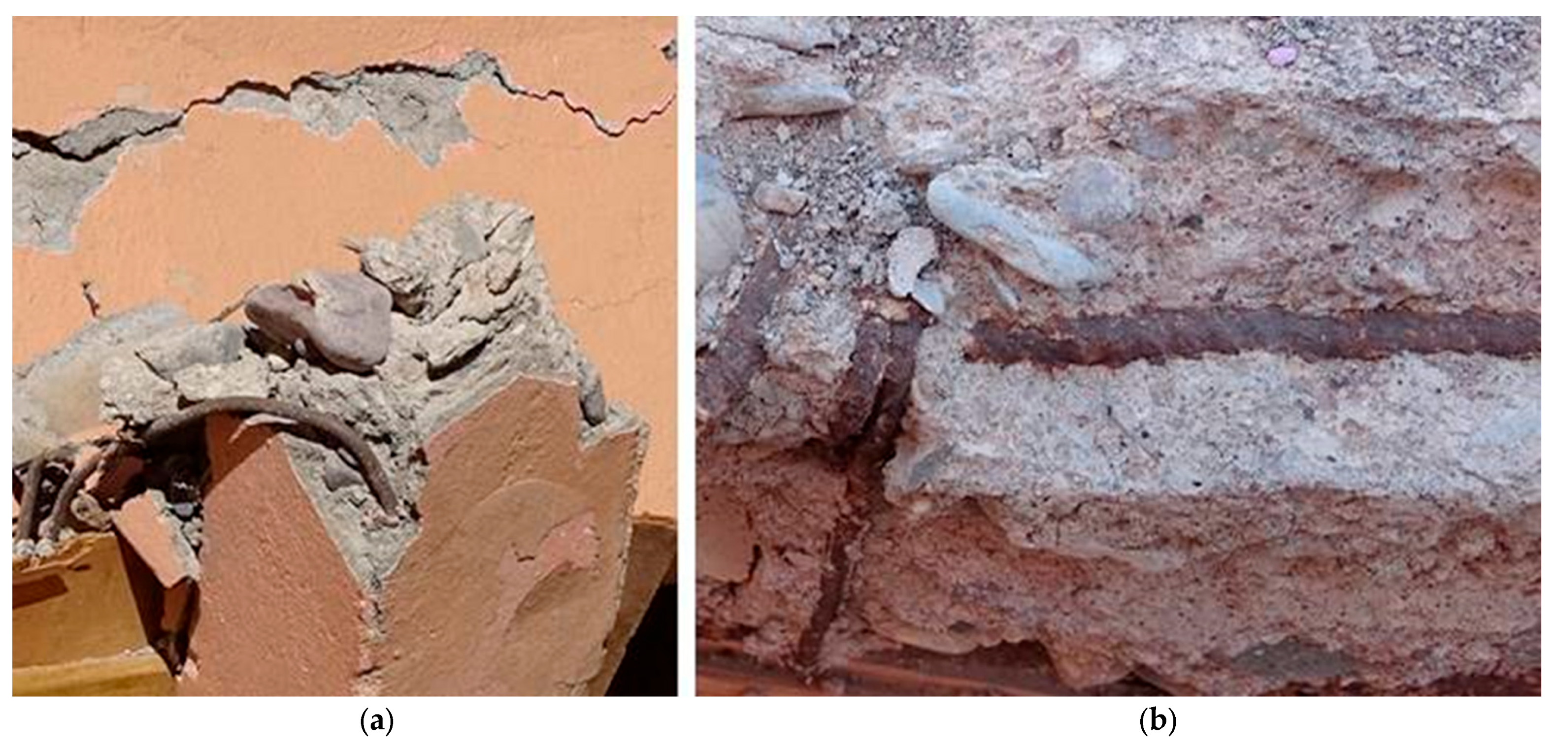
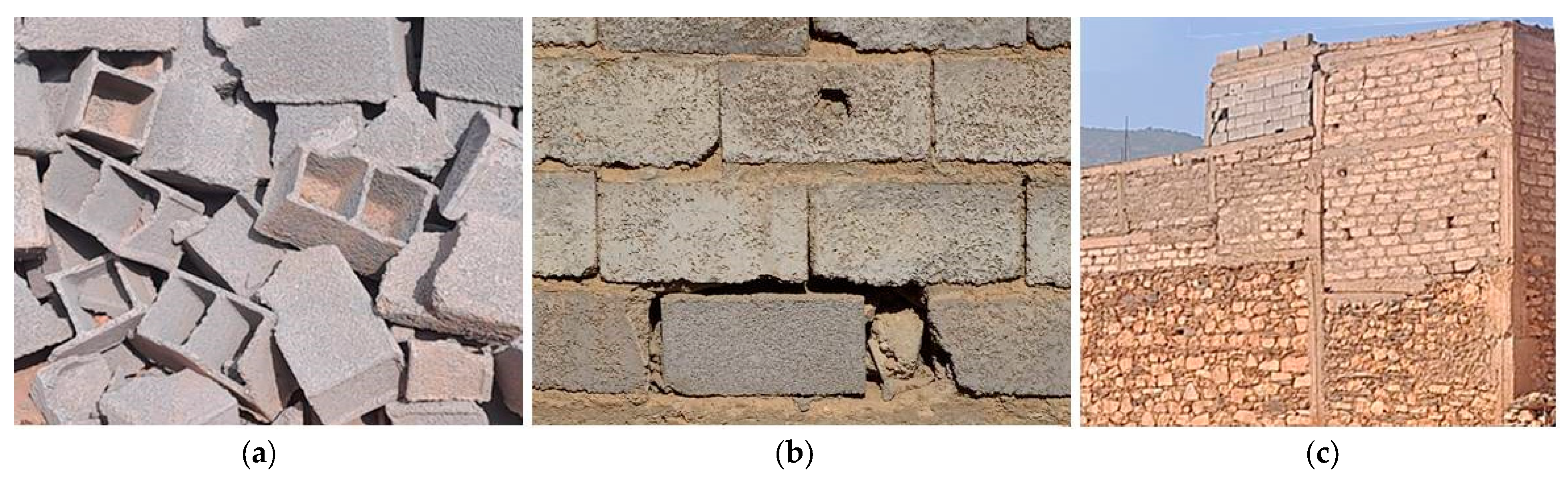
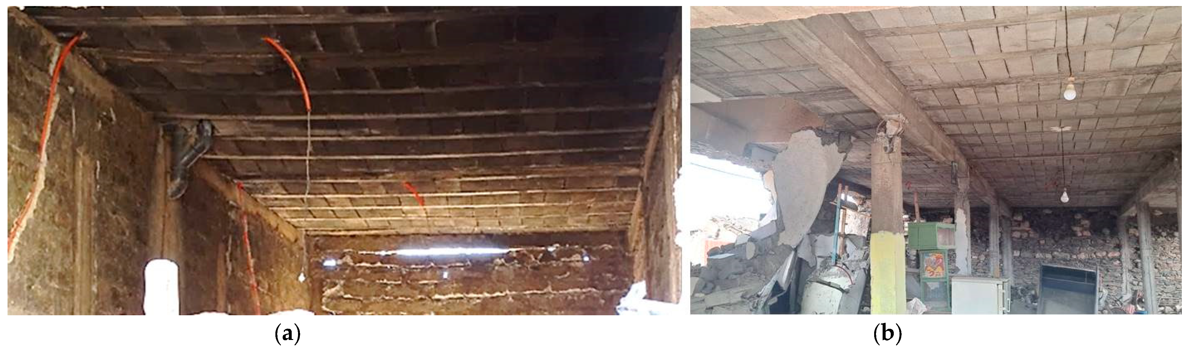
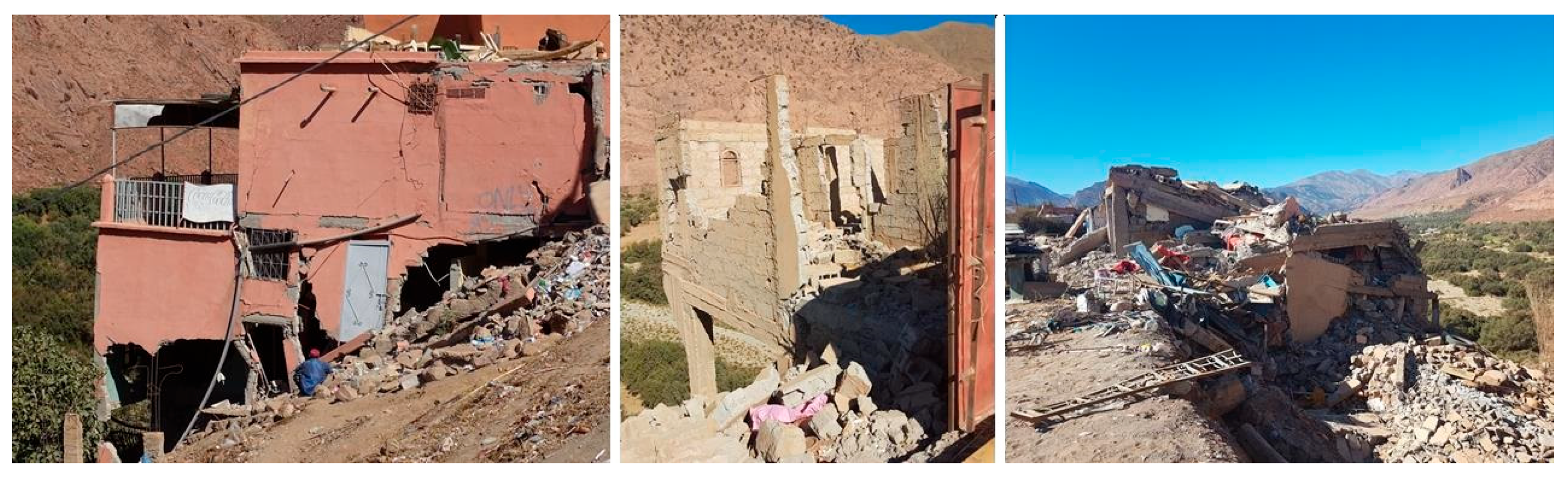
5.2.1. Traditional Construction
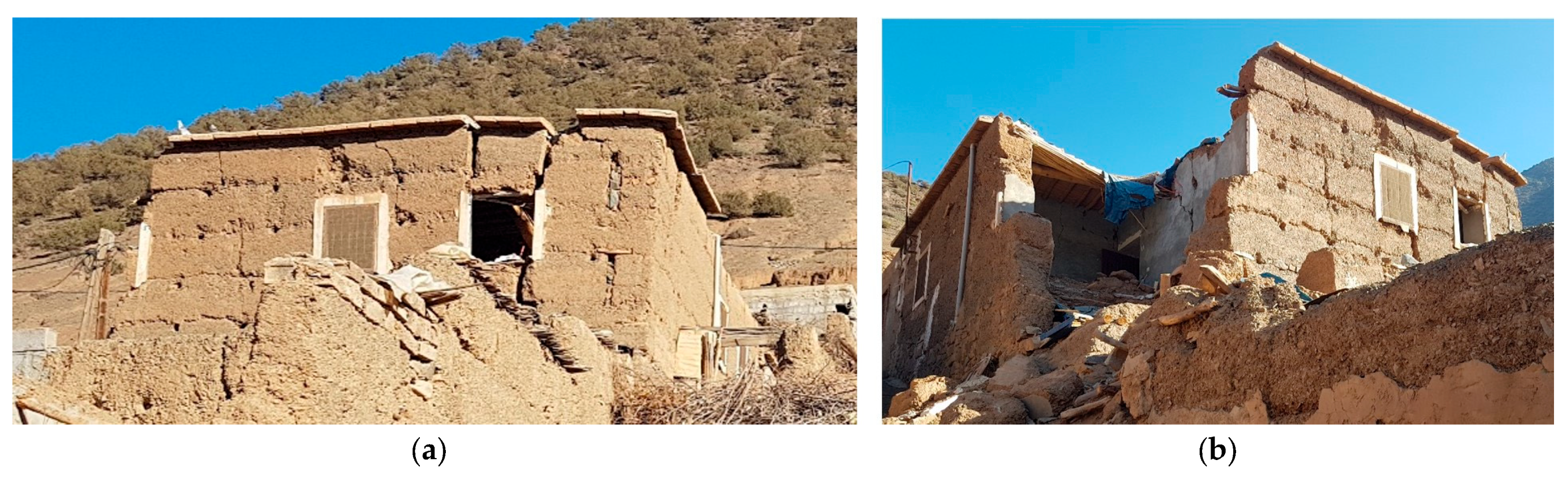
- Rammed-earth wall
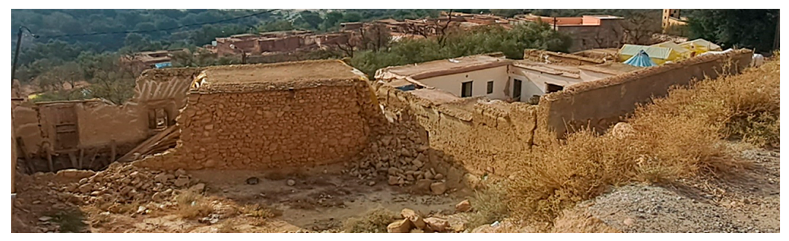
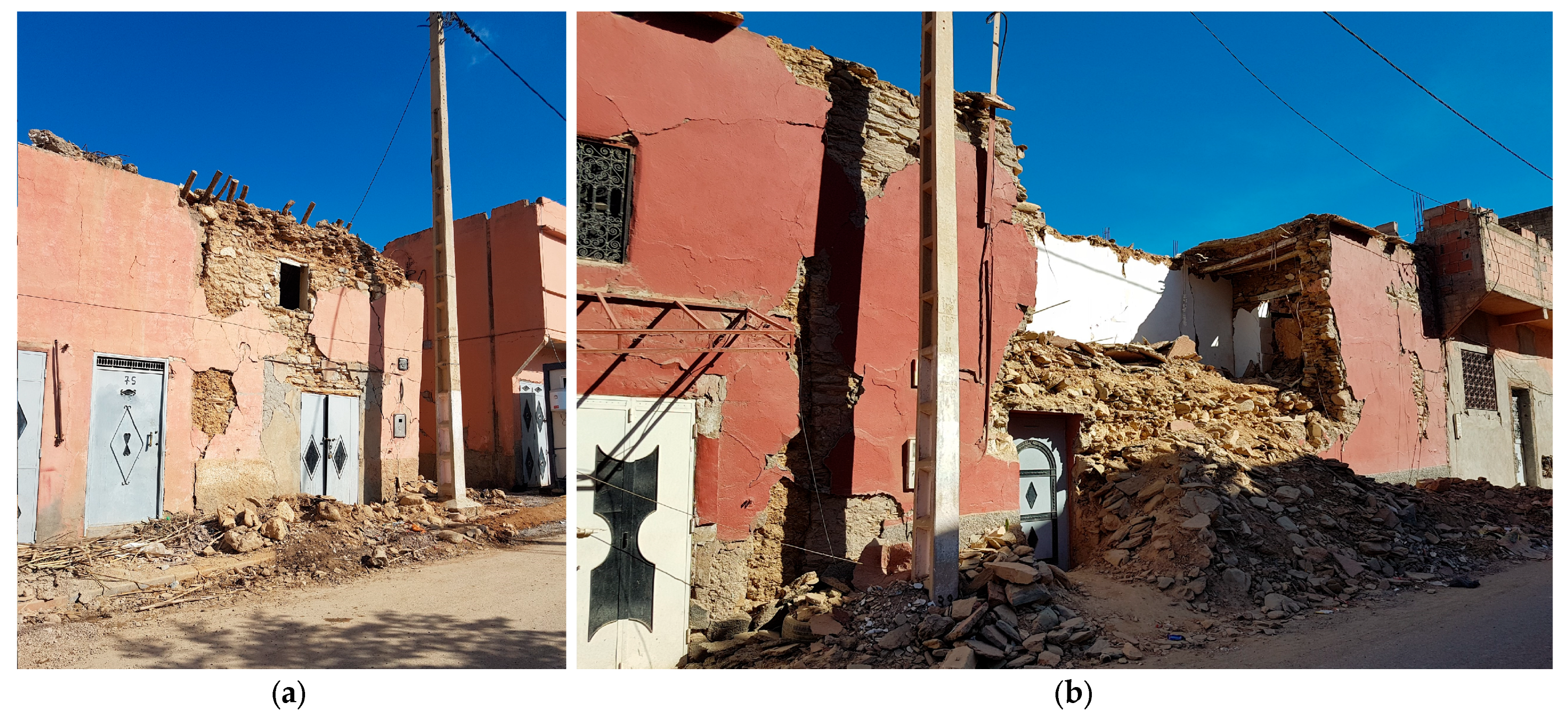
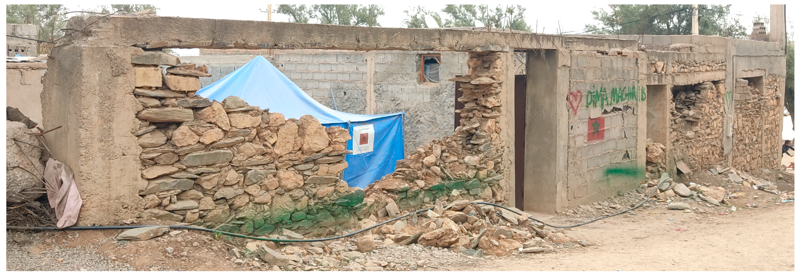
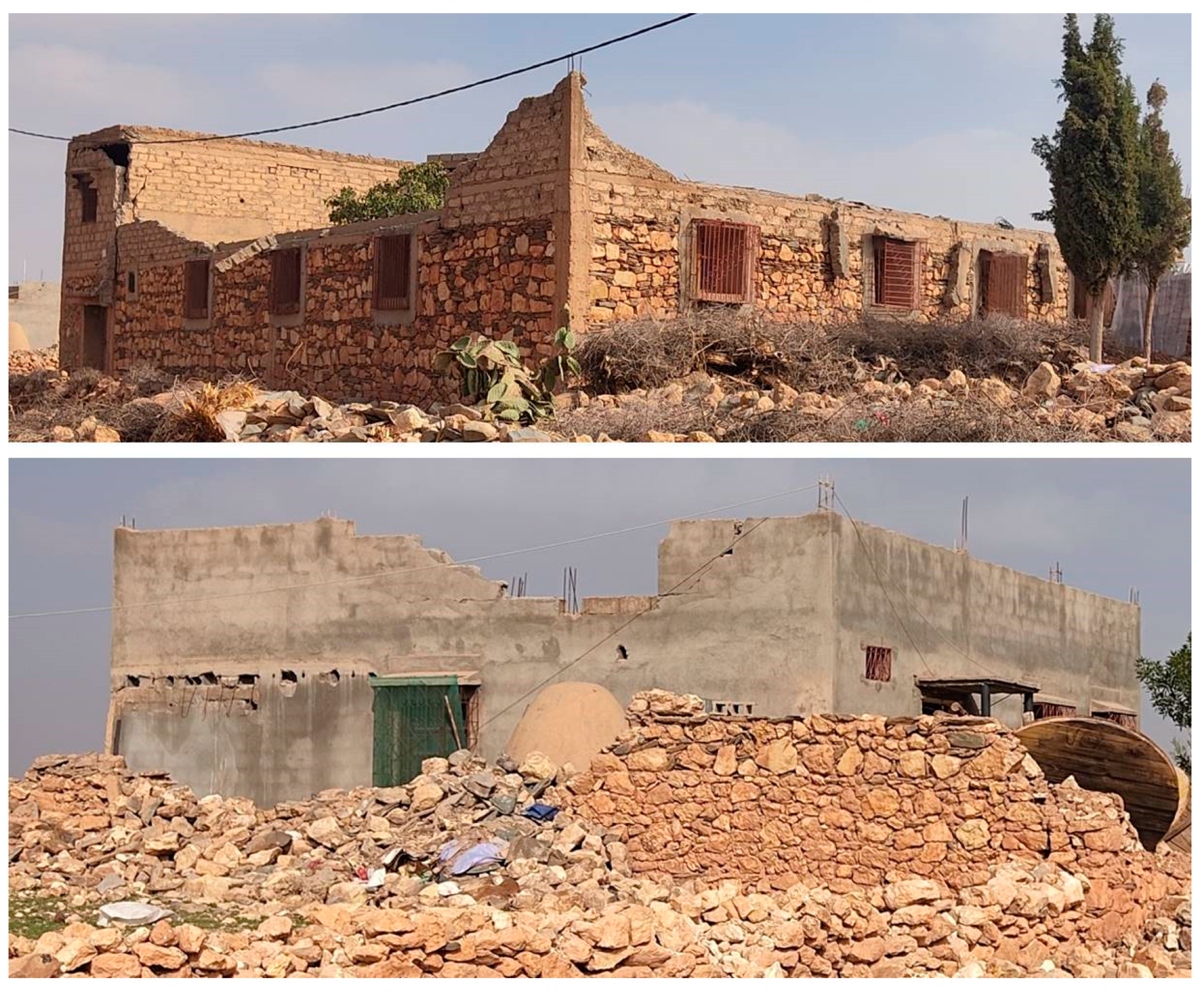
- Unreinforced stone masonry walls
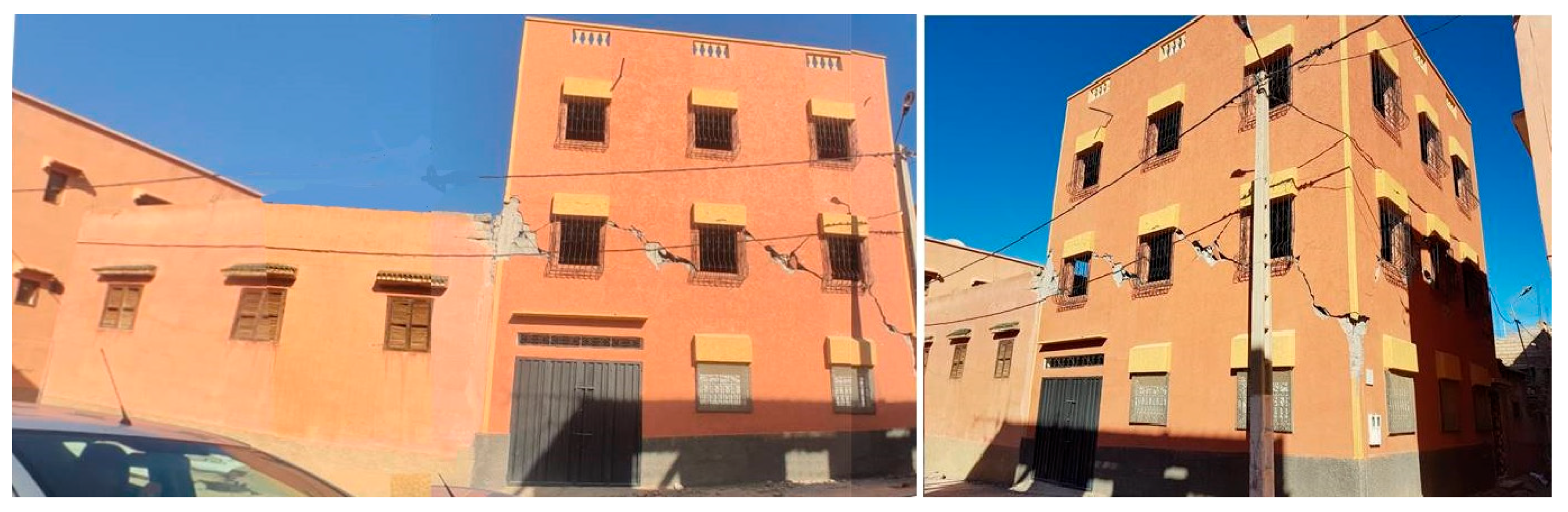
Structural Damage in Traditional Construction Systems
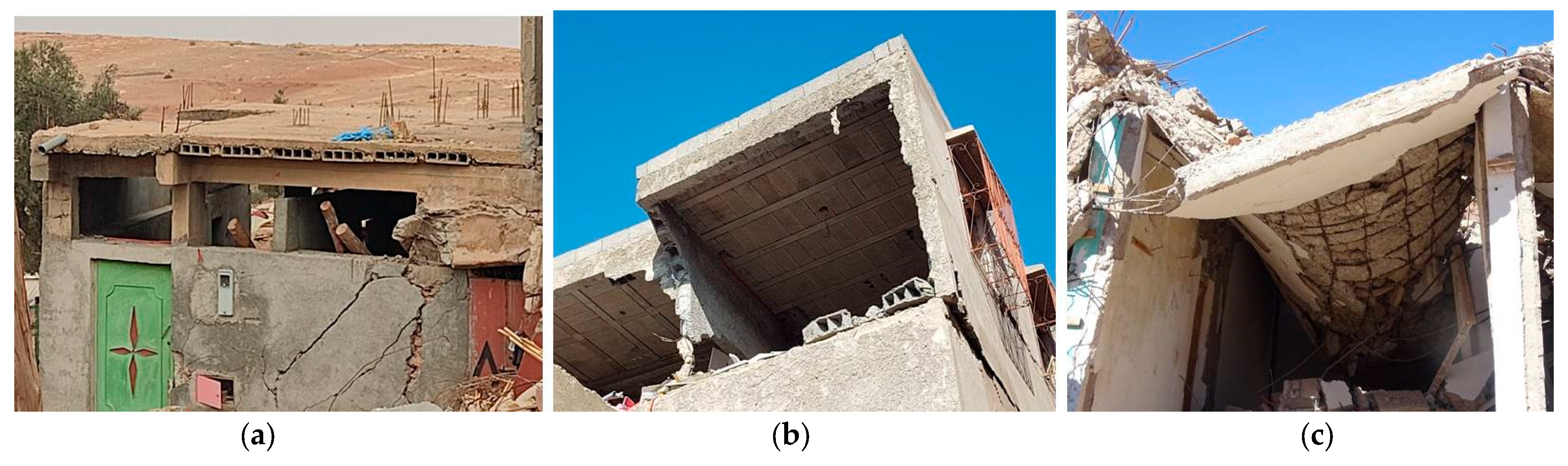
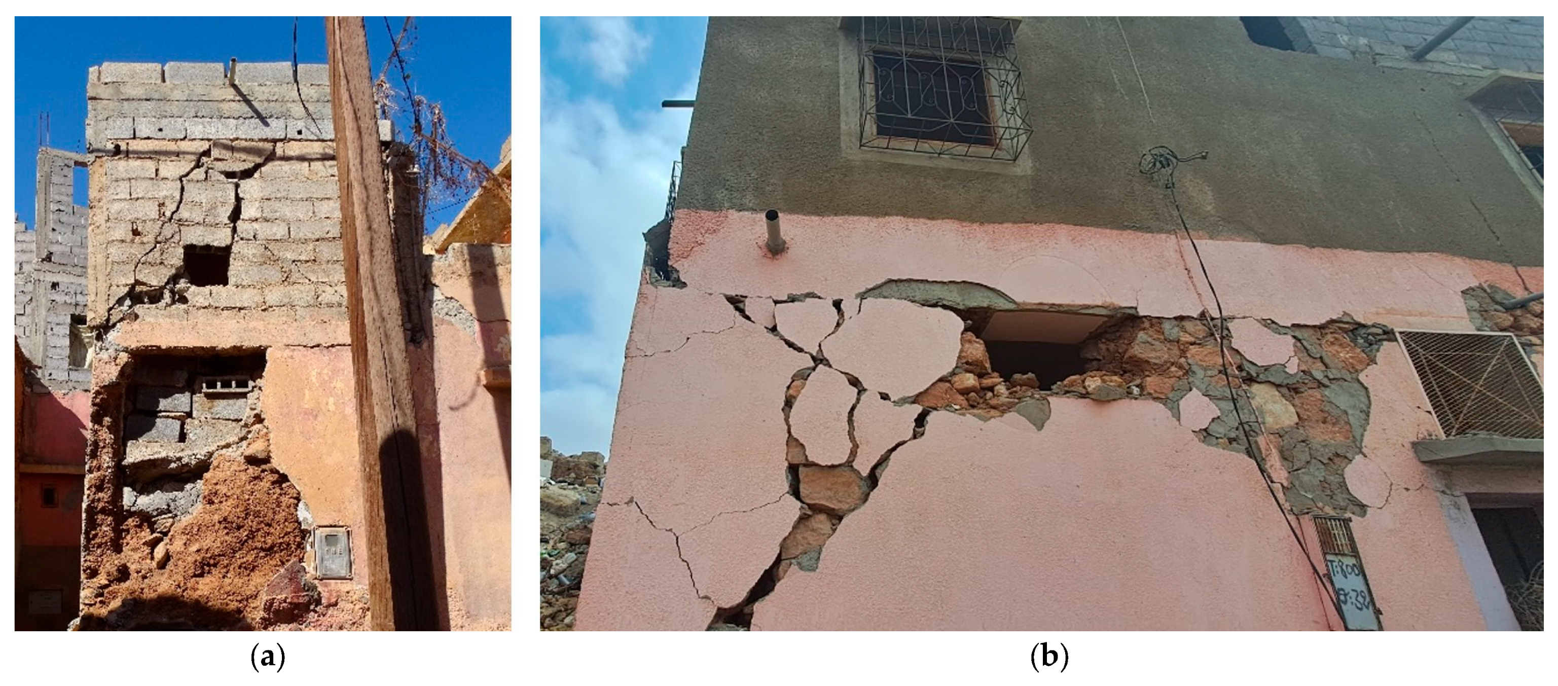
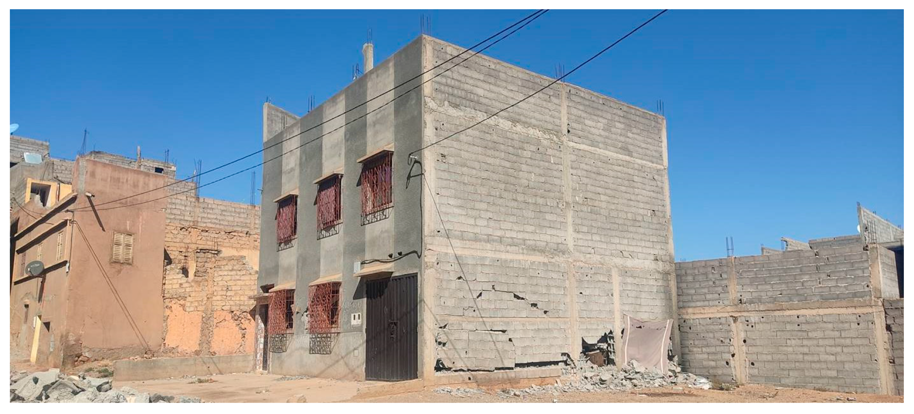
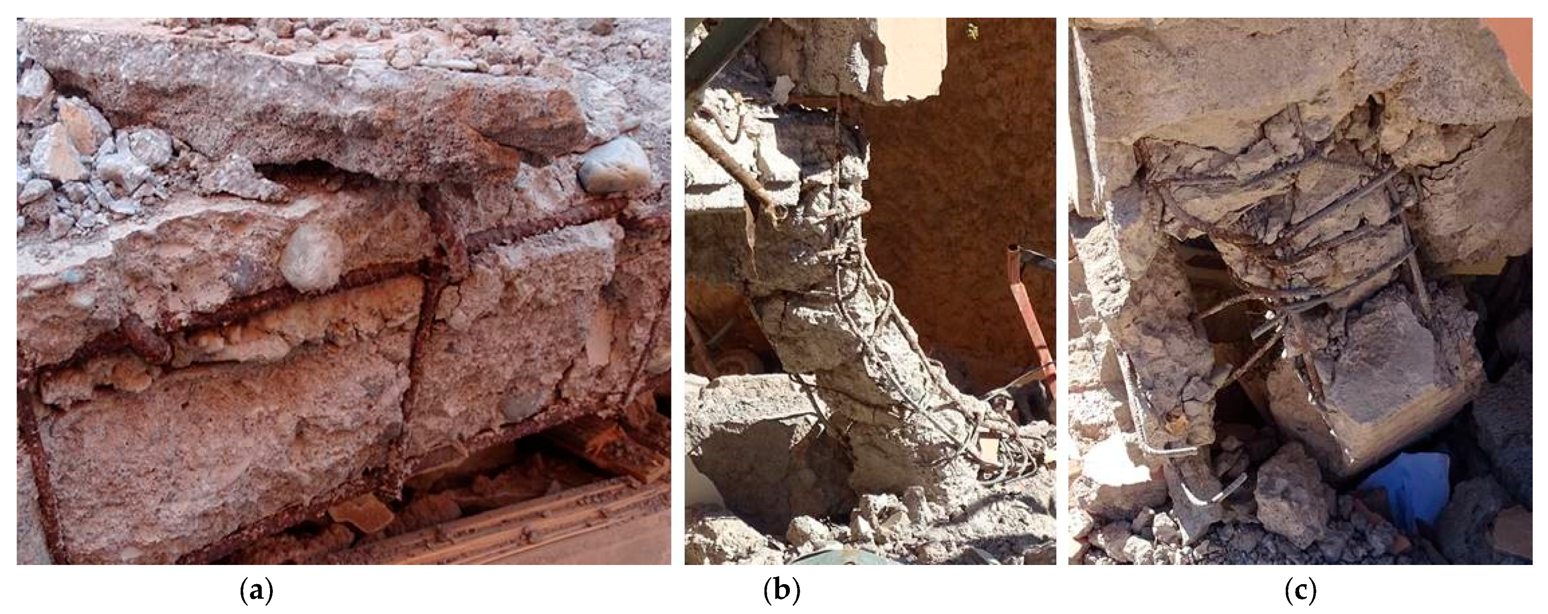
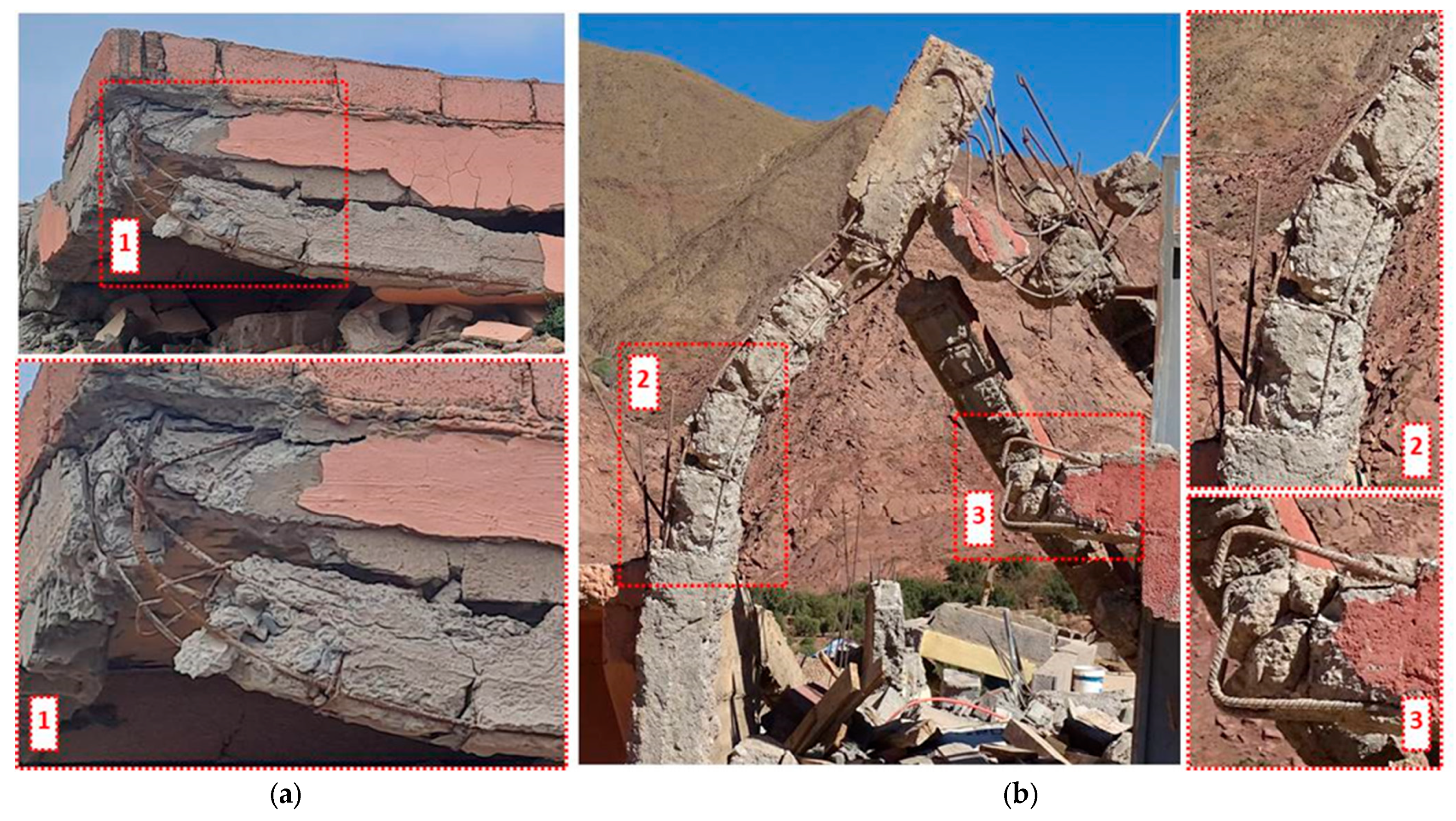
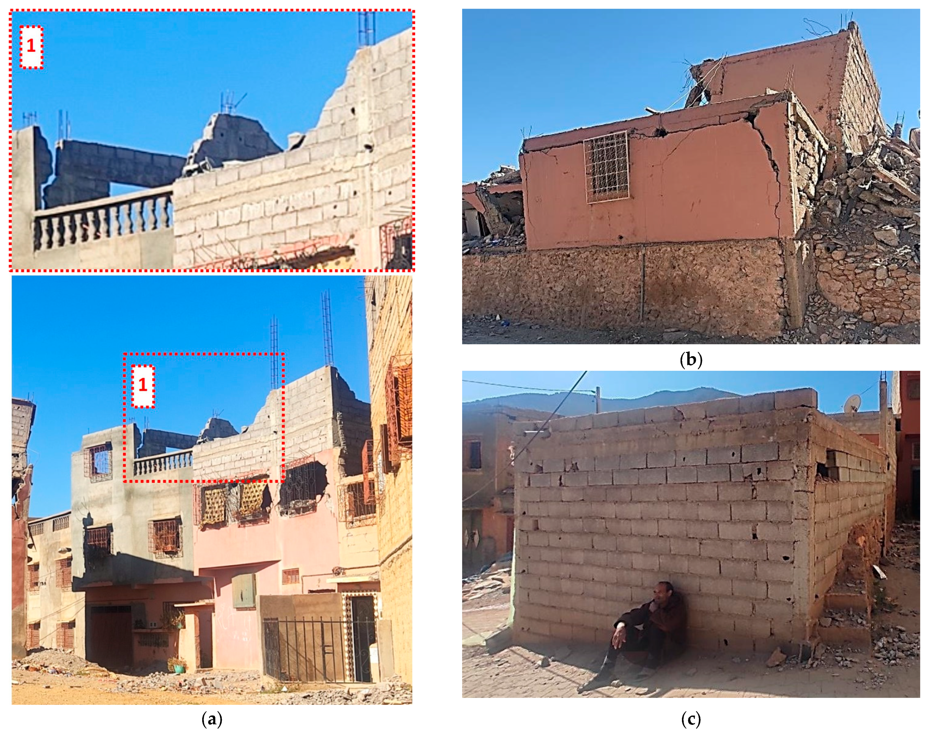
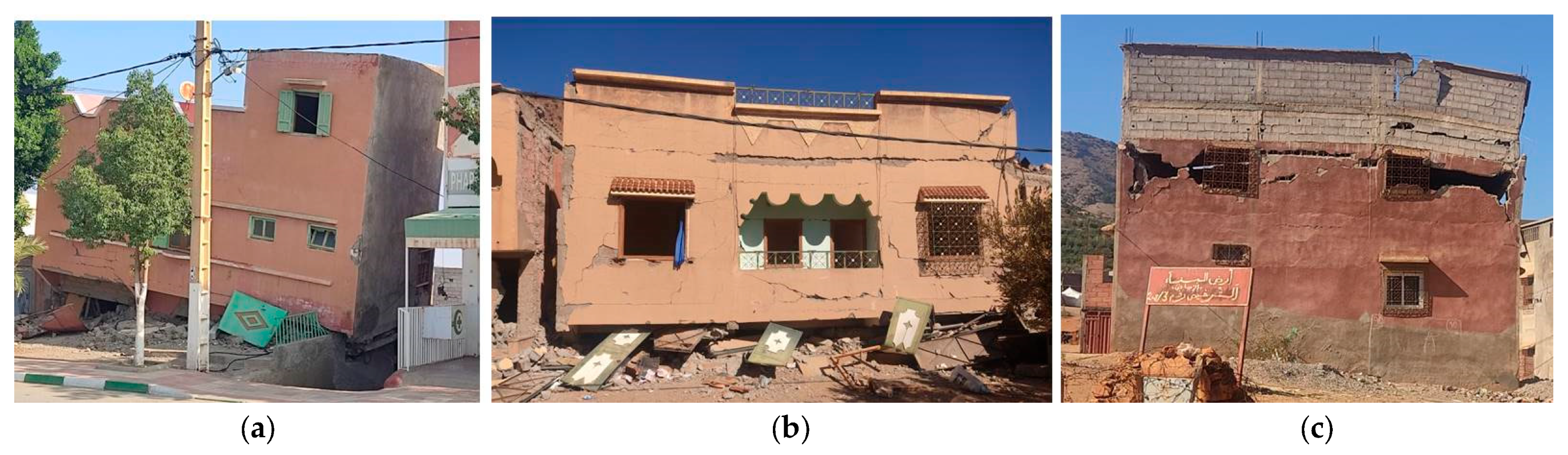
5.2.2. Modern Construction
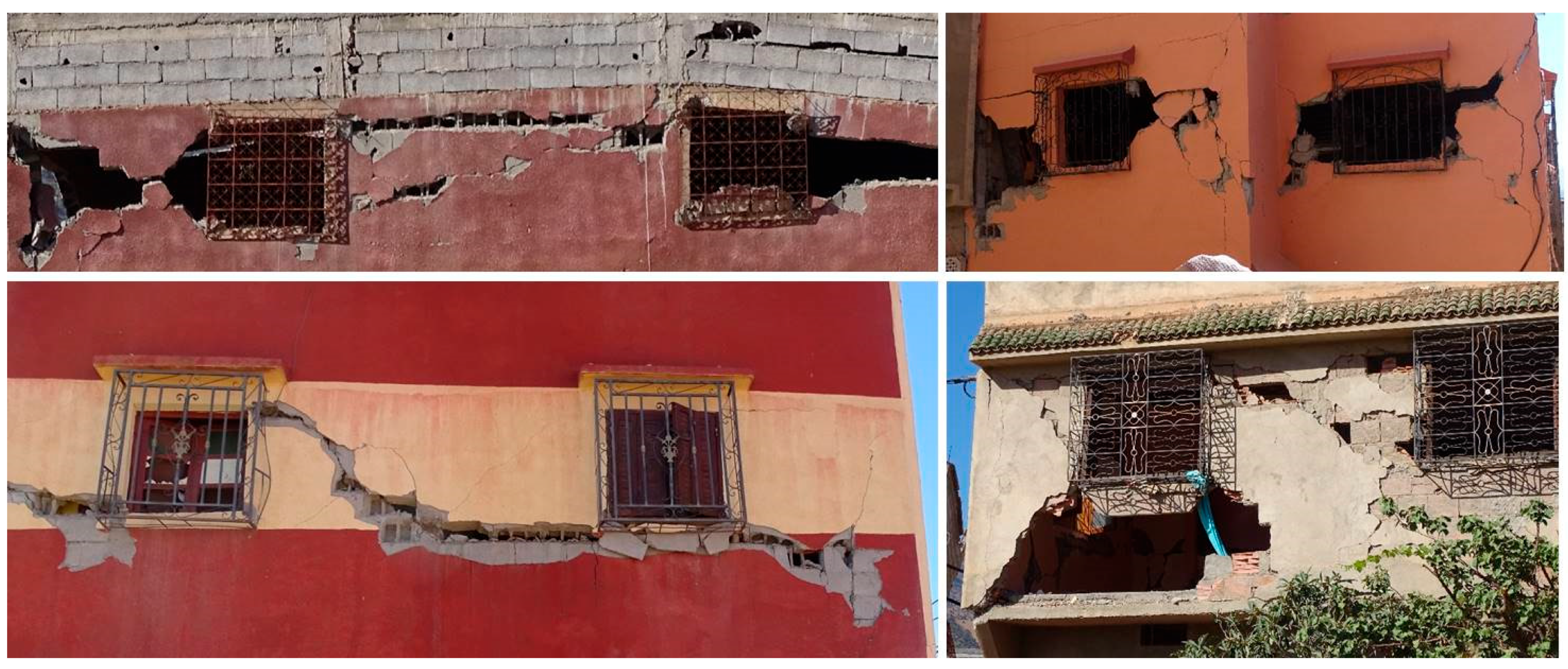
- Confined shear-resistant masonry wall structures
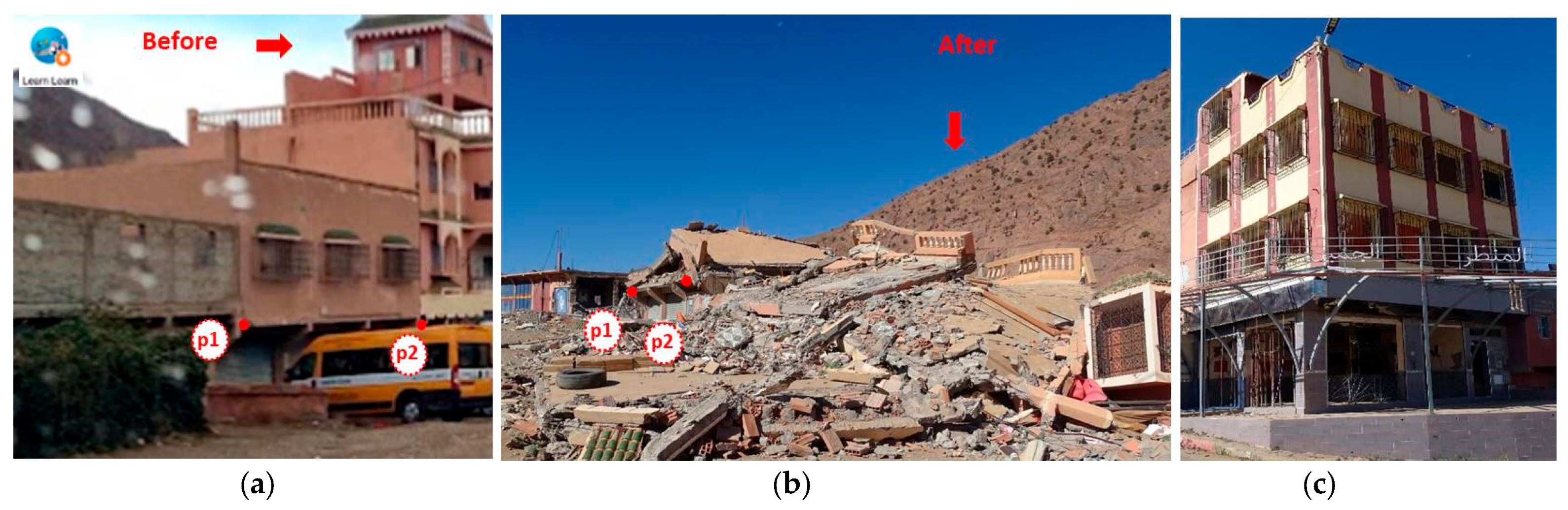
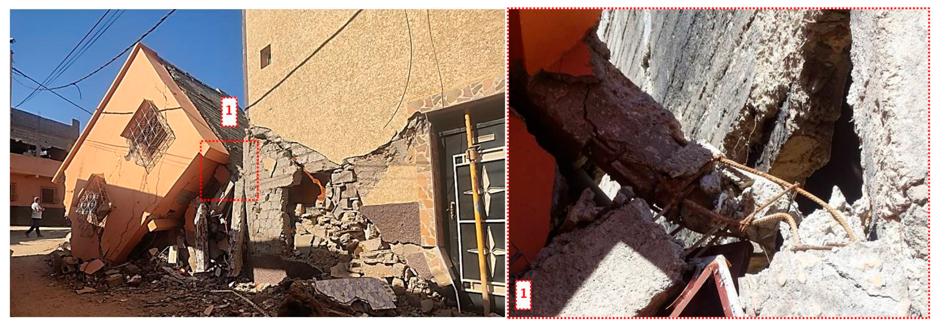
5.2.3. Structural Design and Modifiers Related to the Position of Dwellings in the Block
- Structural design
- Urban position
6. Conclusions and Future Lines of Research
Author Contributions
Funding
Data Availability Statement
Acknowledgments
Conflicts of Interest
References
- Peláez, J.A.; Chourak, M.; Tadili, B.A.; Brahim, L.A.; Hamdache, M.; Casado, C.L.; Solares, J.M.M. A Catalog of Main Moroccan Earthquakes from 1045 to 2005. Seismol. Res. Lett. 2007, 78, 614–621. [Google Scholar] [CrossRef]
- Alami, M.H.; Günay, S.; Mosalam, K.M.; Vargas, L.; Hassan, W.M.; Bektas, N.; Martin, A.; Nobahar, M.; Romão, X.; Zaoui, H.; et al. Morocco Earthquake Preliminary Virtual Reconnaissance Report (PVRR), Virtual. 2023. Available online: https://www.steer.network (accessed on 5 December 2023).
- Cherkaoui, T.E.; El Hassani, A. Seismicity and Seismic Hazard in Morocco 1901–2010. Bull. l’Institut Sci. Sect. Sci. Terre 2012, 34, 45–55. [Google Scholar]
- Jiménez-Munt, I.; Torne, M.; Fernández, M.; Vergés, J.; Kumar, A.; Carballo, A.; García-Castellanos, D. Deep Seated Density Anomalies Across the Iberia-Africa Plate Boundary and Its Topographic Response. J. Geophys. Res. Solid Earth 2019, 124, 13310–13332. [Google Scholar] [CrossRef]
- El Moudnib, L.; Timoulali, Y.; Nouayti, A.; El Abbassi, M.; Bouka, M.; Nouayti, N.; Mhammdi, N. Seismotectonic model of High-Middle Atlas Junction (Morocco) derived from earthquake focal mechanism and stress tensor analysis. Model. Earth Syst. Environ. 2023, 9, 2407–2423. [Google Scholar] [CrossRef]
- Sébrier, M.; Siame, L.; Zouine, E.M.; Winter, T.; Missenard, Y.; Leturmy, P. Active tectonics in the Moroccan High Atlas. Comptes Rendus Geosci. 2006, 338, 65–79. [Google Scholar] [CrossRef]
- U.S. Geological Survey. M 6.8—Al Haouz, Morocco, Earthquake Hazards Program. 2023. Available online: https://earthquake.usgs.gov/earthquakes/eventpage/us7000kufc/executive (accessed on 18 January 2024).
- Euro-Mediterranean Seismological Centre. Quick Moment Tensors Solutions, EMSC. Available online: https://emsc-csem.org/Earthquake_data/data.php?type=mt&id=1550978&base=GCMT_ICYMNKFTD&sub=TD&auth=GCMT&Y=2023&M=09&D=08 (accessed on 18 January 2024).
- Euro-Mediterranean Seismological Centre. Felt Report, EMSC. 2023. Available online: https://emsc-csem.org/Earthquake_information/earthquake_map.php?id=1550978 (accessed on 18 January 2024).
- Rodríguez-Navarro, P.; Vidal, F.J.; Gil-Piqueras, T.; Fantini, F. Earth construction techniques in the Nortern High Atlas, Morocco. In Rammed Earth Conservation; Mileto, C., Vegas, F., Cristini, V., Eds.; Taylor & Francis, Ed.: Oxfordshire, UK, 2012; pp. 569–574. [Google Scholar]
- Costa, M.R.; Batista, D. Architecture traditionnelle dans les zones de montagne: Contribution à l’étude de la typologie des habitations dans le Haut Atlas au Maroc. Digit.-Rev. Digit. de Arqueol. e Arquit. Artes 2018, 2018, 373–397. [Google Scholar] [CrossRef]
- RPS 2000, Règlement de Construction Parasismique; Ministère de l’Habitat et de la Politique de la Ville LE: Rabat, Morocco, 2002.
- RPS 2000 Version 2011. Règlement de Construction Parasismique. 2011. Available online: https://www.sodibet.com/telechargement/RPS2011.pdf (accessed on 1 March 2024).
- Preciado, A.; Santos, J.C. Rammed earth sustainability and durability in seismic areas as a building material. IOP Conf. Ser. Earth Environ. Sci. 2020, 410, 012108. [Google Scholar] [CrossRef]
- Adhikari, R.K.; D’Ayala, D. 2015 Nepal earthquake: Seismic performance and post-earthquake reconstruction of stone in mud mortar masonry buildings. Bull. Earthq. Eng. 2020, 18, 3863–3896. [Google Scholar] [CrossRef]
- Briseghella, B.; Demartino, C.; Fiore, A.; Nuti, C.; Sulpizio, C.; Vanzi, I.; Lavorato, D.; Fiorentino, G. Preliminary data and field observations of the 21st August 2017 Ischia earthquake. Bull. Earthq. Eng. 2019, 17, 1221–1256. [Google Scholar] [CrossRef]
- Penna, A. Seismic assessment of existing and strengthened stone-masonry buildings: Critical issues and possible strategies. Bull. Earthq. Eng. 2015, 13, 1051–1071. [Google Scholar] [CrossRef]
- Chidiac, S.E.; Foo, S. Guidelines for the Seismic Upgrading of Stone-Masonry Structures; Public Works & Government Services Canada: North York, ON, Canada, 2002; Volume 84. [CrossRef]
- Dizhur, D.; Dhakal, R.P.; Bothara, J.; Ingham, J.M. Building typologies and failure modes observed in the 2015 Gorkha (Nepal) earthquake. Bull. N. Zealand Soc. Earthq. Eng. 2016, 49, 211–232. [Google Scholar] [CrossRef]
- Murphy, P. Al-Hoceima Earthquake 24 02 2004; Seismic Engineering: Madrid, Spain, 2004. [Google Scholar]
- Bothara, J.K.; Hiçyılmaz KM, O. General observations of building behaviour during the 8th October 2005 Paquistan earthquake. Bull. N. Zeal. Soc. Earthq. Eng. 2008, 41, 209–233. [Google Scholar]
- Rejas Ayuga, J.G.; Martínez Marín, R.; Malpica Velasco, J.A. Hyperspectral remote sensing application for semi-urban areas monitoring. In Proceedings of the 2007 Urban Remote Sensing Joint Event, Paris, France, 11–13 April 2007. [Google Scholar] [CrossRef]
- Masi, A.; Chiauzzi, L.; Santarsiero, G.; Liuzzi, M.; Tramutoli, V. Seismic damage recognition based on field survey and remote sensing: General remarks and examples from the 2016 Central Italy earthquake. Nat. Hazards 2017, 86, 193–195. [Google Scholar] [CrossRef]
- Pouget, M.; Madeira, J.; Le Floc’h, E.; Kamal, S. Caracteristiques spectrales des surfaces sableuses de la region cotiere nord-ouest de l’egypte: Application aux donnees satellitaires spot. Caracter. Et Suivi Des Milieux Terr. En Reg. Arid. Et Trop. 1991, 27–38. [Google Scholar]
- Huete, A.R. A soil-adjuste d vegetation index (SAVI). Remote Sens. Environ. 1988, 25, 295–309. [Google Scholar] [CrossRef]
- Saito, R.; Spence, K. Rapid damage mapping using post-earthquake satellite images in IGARSS 2004. In Proceedings of the 2004 IEEE International Geoscience and Remote Sensing Symposium, Anchorage, AK, USA, 20–24 September 2004; pp. 2272–2275. [Google Scholar] [CrossRef]
- Masi, A.; Santarsiero, G.; Digrisolo, A.; Chiauzzi, L.; Manfredi, V. Procedures and experiences in the post-earthquake usability evaluation of ordinary buildings. Boll. Geofis. Teor. Appl. 2016, 57, 199–200. [Google Scholar] [CrossRef]
- Arthur, D.; Vassilvitskii, S. K-means++: The advantages of careful seeding. Proc. Annu. ACM-SIAM Symp. Discret. Algorithms 2007, 7, 1027–1035. [Google Scholar]
- An, L.; Zhang, J.; Gong, L.; Li, Q. Integration of SAR image and vulnerability data for building damage degree estimation. In Proceedings of the 2016 IEEE International Geoscience and Remote Sensing Symposium (IGARSS), Beijing, China, 10–15 July 2016; pp. 4263–4266. [Google Scholar] [CrossRef]
- Zhai, W.; Shen, H.-F.; Huang, C.-L.; Pei, W.-S. Building damage information investigation after earthquake using single post-event PolSAR image. In Proceedings of the 2016 IEEE International Geoscience and Remote Sensing Symposium (IGARSS), Beijing, China, 10–15 July 2016; pp. 7338–7341. [Google Scholar] [CrossRef]
- Grünthal, G. European Macroseismic Scale; Council of Europe: Luxembourg, 1998; Volume 15.
- Ministère de l’Habitat et de la Politique de la Ville. Guide Practique D’utilitation du Reglement de Costruction Parasismique (RPS 2000 Version 2011); Ministère de l’Habitat et de la Politique de la Ville: Rabat, Morocco, 2013; pp. 1–201. Available online: https://www.mhpv.gov.ma/wp-content/uploads/2023/10/Guide-RPS-2011-V2011-Francais.pdf (accessed on 1 March 2024).
- Cherif, S.-E.; Chourak, M.; Abed, M.; Douiri, A. Potential seismic damage assessment of residential buildings in Imzouren City (Northern Morocco). Buildings 2018, 8, 179. [Google Scholar] [CrossRef]
- Taucer, F.; Pinto Vieira, A. Field Manual for Post-Earthquake Damage and Safety Assessment and Short Term Countermeasures (AeDES). Eur. Comm.—Jt. Res. Cent.—Inst. Prot. Secur. Citiz. EUR 22868 2007, JRC37914. [Google Scholar]
- D’Ayala, D.; Speranza, E. An Integrated Procedure for the Assessment. In Proceedings of the 12th European Conference Earthquake Engineering, London, UK, 9–13 September 2002. [Google Scholar]
- D’Ayala, D.; Speranza, E. Definition of collapse mechanisms and seismic vulnerability of historic masonry buildings. Earthq. Spectra 2003, 19, 479–509. [Google Scholar] [CrossRef]
- Bilgin, H.; Leti, M.; Shehu, R.; Özmen, H.B.; Deringol, A.H.; Ormeni, R. Reflections from the 2019 Durrës Earthquakes: An Earthquake Engineering Evaluation for Masonry Typologies. Buildings 2023, 13, 2227. [Google Scholar] [CrossRef]
- Angiolilli, M.; Brunelli, A.; Cattari, S. Fragility Curves of Masonry Buildings in Aggregate Accounting for Local Mechanisms and Site Effects; Springer: Dordrecht, The Netherlands, 2023; Volume 21. [Google Scholar]
- D’Ayala, D.F.; Paganoni, S. Assessment and analysis of damage in L’Aquila historic city centre after 6th April 2009. Bull. Earthq. Eng. 2011, 9, 81–104. [Google Scholar] [CrossRef]
- Torres-Olivares, S.; González-Rodrigo, B.; Saavedra-Flores, E.I.; Feijoo-Mosquera, J.C. Seismic behaviour of reinforced—Masonry aggregate under different types of interaction between adjacent dwellings. Bull. Earthq. Eng. 2024, 22, 583–609. [Google Scholar] [CrossRef]
- UNE EN 1998; EN1998 Eurocode 8: Design of Structures for Earthquake Resistance—Part 1: General Rules, Seismic Actions and Rules for Buildings. European Committee for Standardizatio: Brussels, Belgium, 2011.
- ACI 318R-05; Building Code Requirements for Structural Concrete (ACI 318-05) and Commentary. ACI Committee: Farmington Hills, MI, USA, 2005.
- Milutinovic, Z.V.; Trendafiloski, G.S. RISK-UE An Advanced Approach to Earthquake Risk Scenarios with Applications to Different European Towns; WP4: Vulnerability of Current Buildings; European Commission: Brussels, Belgium, 2003; pp. 1–111.
- Lindeburg, M.R. Seismic Design of Building Structures: A Professional’s Introduction to Earthquake Forces and Design Details; Belmont, C., Ed.; EEUU: Stanford, CA, USA, 1996. [Google Scholar]
- Enrique, B.; Meli, R. Diseño Sísmico de Edificios; Limusa: Mexico City, Mexico, 2010. [Google Scholar]
- Angiolilli, M.; Lagomarsino, S.; Cattari, S.; Degli Abbati, S. Seismic fragility assessment of existing masonry buildings in aggregate. Eng. Struct. 2021, 247, 113218. [Google Scholar] [CrossRef]
- Battaglia, L.; Ferreira, T.M.; Lourenço, P.B. Seismic fragility assessment of masonry building aggregates: A case study in the old city Centre of Seixal, Portugal. Earthq. Eng. Struct. Dyn. 2020, 50, 1358–1377. [Google Scholar] [CrossRef]
- Valente, M.; Milani, G.; Grande, E.; Formisano, A. Historical masonry building aggregates: Advanced numerical insight for an effective seismic assessment on two row housing compounds. Eng. Struct. 2019, 190, 360–379. [Google Scholar] [CrossRef]
- Chieffo, N.; Formisano, A. Comparative Seismic Assessment Methods for Masonry Building Aggregates: A Case Study. Front. Built Environ. 2019, 5, 123. [Google Scholar] [CrossRef]
- Formisano, A.; Ademovic, N. An overview on seismic analysis of masonry building aggregates. Front. Built Environ. 2022, 8, 966281. [Google Scholar] [CrossRef]
- Miari, M.; Choong, K.K.; Jankowski, R. Seismic pounding between adjacent buildings: Identification of parameters, soil interaction issues and mitigation measures. Soil Dyn. Earthq. Eng. 2019, 121, 135–150. [Google Scholar] [CrossRef]
- Chieffo, N.; Formisano, A.; Lourenço, P.B. Seismic vulnerability procedures for historical masonry structural aggregates: Analysis of the historical centre of Castelpoto (South Italy). Structures 2023, 48, 852–866. [Google Scholar] [CrossRef]


| Zone | Coordinates (WGS34) | Epicentral Distance Orientation | Image Size Spatial Resolution | Before Date After Date | Copyright Image |
|---|---|---|---|---|---|
| Amizmiz | 31°12′53.06″ N | 22 Km | 1578 × 940 pixels | September 2020 | Airbus |
| 8°14′48.87″ W | 57º N | 0.5 m | October 2023 | Airbus | |
| Tafeghaghte | 31°11′48.01″ N | 23 Km | 1564 × 930 pixel | June 2022 | Maxar Technologies |
| 8°13′25.74” W | 65º N | 0.5 m | September 2023 | Airbus | |
| Adassil | 31°7′6.72″ N | 5 Km | 1572 × 933 pixel | April 2022 | Maxar Technologies |
| 8°29′27.02″ W | 238º N | 0.5 m | October 2023 | Airbus | |
| Talat N’Yaqoud | 30°59′31.28″ N | 27 Km | 1577 × 939 pixel | June 2022 | Maxar Technologies |
| 8°11′2.32″ W | 118º N | 0.5 m | September 2023 | Airbus |
| Village % Image Change; % Structures Change | ||
|---|---|---|
| Image after the Earthquake | Image before the Earthquake | Change |
| Amizmiz −44% image change; −5% structure change | ||
 |  | 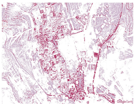 |
| Tafeghaghte −69% image change; −27% structure change | ||
 | 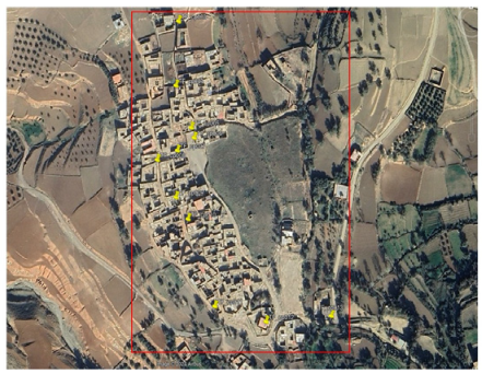 |  |
| Adassil −47% image change; −21% structure change | ||
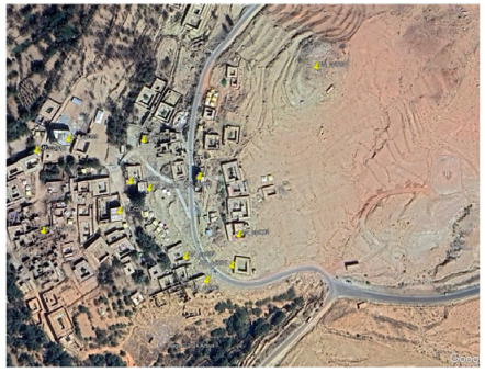 |  | 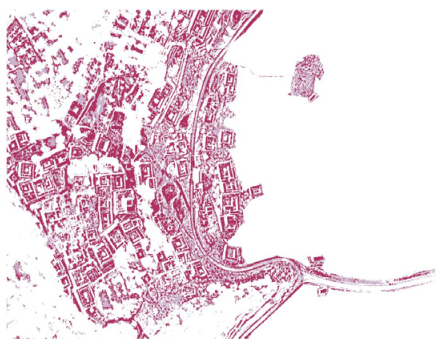 |
| Talat N’Yaaqoud −72% image change; −35% structure change | ||
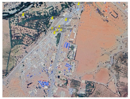 | 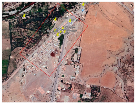 | 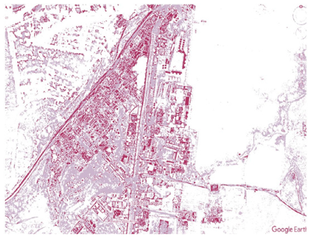 |
| Structural Lateral System (Typical Thickness) | Flooring System | Typical Number of Floors | Schema |
|---|---|---|---|
| Traditional Construction | |||
| Rammed-earth wall (50 to 60 cm) | Wooden beams covered with straw and compacted earth | 1 to 3 | 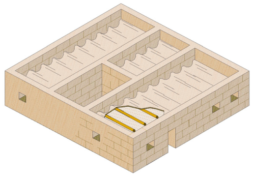 |
| Unreinforced stone masonry walls: rounded or quarry stones bound together with a weak, irregularly bonded mud mortar (40 to 90 cm) | Unidirectional wooden flooring system filled with straw and a layer of mortar or rammed earth | 1 to 2 |  |
| Modern Construction | |||
| Mixed: hybrid behavior between masonry-filled RC frame structures working in flexure and confined (with RC beam and columns) shear-resistant masonry wall structures (10 to 25 cm) | RC joists and concrete hollow blocks with a reinforced or unreinforced compression deck layer | 1 to 4 |  |
Disclaimer/Publisher’s Note: The statements, opinions and data contained in all publications are solely those of the individual author(s) and contributor(s) and not of MDPI and/or the editor(s). MDPI and/or the editor(s) disclaim responsibility for any injury to people or property resulting from any ideas, methods, instructions or products referred to in the content. |
© 2024 by the authors. Licensee MDPI, Basel, Switzerland. This article is an open access article distributed under the terms and conditions of the Creative Commons Attribution (CC BY) license (https://creativecommons.org/licenses/by/4.0/).
Share and Cite
González-Rodrigo, B.; Navas-Sánchez, L.; Rejas-Ayuga, J.G.; Hernández-Rubio, O.; Benito, M.B. Preliminary Geospatial and In Situ Reconnaissance of the 8 September 2023 Moroccan Atlas Earthquake Damage. Buildings 2024, 14, 693. https://doi.org/10.3390/buildings14030693
González-Rodrigo B, Navas-Sánchez L, Rejas-Ayuga JG, Hernández-Rubio O, Benito MB. Preliminary Geospatial and In Situ Reconnaissance of the 8 September 2023 Moroccan Atlas Earthquake Damage. Buildings. 2024; 14(3):693. https://doi.org/10.3390/buildings14030693
Chicago/Turabian StyleGonzález-Rodrigo, Beatriz, Laura Navas-Sánchez, Juan Gregorio Rejas-Ayuga, Orlando Hernández-Rubio, and María Belén Benito. 2024. "Preliminary Geospatial and In Situ Reconnaissance of the 8 September 2023 Moroccan Atlas Earthquake Damage" Buildings 14, no. 3: 693. https://doi.org/10.3390/buildings14030693
APA StyleGonzález-Rodrigo, B., Navas-Sánchez, L., Rejas-Ayuga, J. G., Hernández-Rubio, O., & Benito, M. B. (2024). Preliminary Geospatial and In Situ Reconnaissance of the 8 September 2023 Moroccan Atlas Earthquake Damage. Buildings, 14(3), 693. https://doi.org/10.3390/buildings14030693