Abstract
The utilisation of box girders with corrugated steel webs (CSWs) represents an innovative approach to bridge superstructure design that has garnered substantial popularity worldwide, with a notable prevalence in both Asia and Europe. Compared with traditional box girders, they avoid web cracking, improving the prestressing efficiency and bridge spanning ability. As an innovative box girder, a corrugated web can increase the cantilever length and transverse stiffness, and at the same time, it reduces the dead weight of the bridge deck. However, little research has been conducted on the mechanical properties of this novel spine-like box girder with CSWs, especially its transverse performance, although it has been used in many applications. In this paper, the effect of the web form on the behaviour of box girders is introduced. Therefore, three representative three-dimensional (3D) finite-element models (i.e., corrugated web box girder, flat web box girder, and ordinary equivalent concrete web box girder) have been established to quantitatively investigate the influence of corrugated web stiffness on transverse stress under the action of gravity and vehicle loads. Generally, significant differences in the mechanical performance of box girders with CSWs have been observed compared with conventional box girders with concrete webs. Additionally, parametric studies to investigate the influences of the corrugation dimensions (in term of the corrugation height, web thickness, panel width, web height and elastic modulus) on the transverse stiffness of such bridges are analyzed. The results show that a new stiffness formula can be put forward to consider the effect of web height, and a high-strength steel web needs to be developed urgently for box girders with CSWs in the near future. Overall, the results of this investigation can be used as a reference for transverse designing and segmental construction of similar projects.
1. Introduction
Corrugated plates are widely used in many industrial fields such as profiled steel sheets in containers, construction fences in infrastructure constructions, steel beams and columns of industrial factories, arch bridges, cable-stayed bridges and girder bridges. A box girder bridge with corrugated steel webs (CSWs) is a new type of composite bridge. Due to its unique structural features and light weight, it is one of the preferred composite structures in Asia’s bridge engineering because of both its engineering economic value and aesthetic appearance. It consists of folded steel webs, along with top and bottom concrete flanges. In this design, the concrete flanges are responsible for withstanding axial forces and bending moments, while the CSWs bear shear forces, effectively utilizing the material strength of both concrete and steel. On the other hand, for single box girder bridges with the same dimensions, the traditional single-cell box girder (i.e., the two-webbed box section) with ordinary concrete webs has many shortcomings such as the decline in the bearing capacity caused by concrete web cracking, the increase in shear deformation and deflection caused by concrete structure self-weight and prestressing loss. Compared with traditional concrete webs, CSWs effectively solve the problem of web cracking. This novel structure, indeed, has many other advantages, such as its high prestressing efficiency and convenience for assembly construction. It has been widely applied in Japan and has recently been vigorously promoted in China [1]. With the maturing of design theory of bridge girders and improvements in the level of manufacture and construction, this new type of bridge is becoming increasingly competitive in medium- and large-span bridge construction.
By reviewing the existing literature, it could be found that many scholars have focused on the buckling behaviour of the box girder bridge with CSWs. This included local and global buckling as well as interactive buckling of straight girders with CSWs, because shear buckling is the controlling factor in the design of such girders [2,3,4,5,6,7,8,9]. With the increase in urban populations and traffic flow, prestressed concrete wide box girders have been increasingly used for constructing new bridges and/or reconstructing old bridges. In general, the length of the side cantilever of a conventional box girder is less than 4 m, and the transverse bending moment capacity is the controlling factor for the dimensions of the bridge deck.
The study of its transverse performance can be traced to ordinary continuous concrete box girders. Guo and Zheng [10] delivered the “TYL” framework analysis method of transverse internal force analysis of box girders, which was recommended by the American Bridge Handbook and then extended to the rectangular box girder with cantilever. Some scholars have conducted quantitative studies on the basic mechanical behaviour of the concrete box girder structure. Zheng and Liu [11] briefly introduced the structural forms and mechanical characteristics of wide box girders. The transverse stress of the ribbed concrete wide box girder was analysed by Zhou et al. [12], and it was found that the rib has a certain reduction effect on the transverse stress. The strutted box widening method (SBWM) was, as well, introduced to allow a two-lane concrete bridge to be designed and constructed so that it can easily be widened into a three- or four-lane bridge due to future traffic volume increase. Additionally, based on the folded plate method in conjunction with a plane frame analysis, the computer program STRUTBOX allows for deck prestressing and other reinforcing to be proportioned for transverse flexure [13,14,15].
On the other hand, the arching action, compressive membrane action and geometric arching are important issues that have been considered in the literature, with particular emphasis on their effects on bridge decks. Generally, the analytical methods including arching action significantly reduce the required amount of reinforcement for the deck slab. Additionally, it has been concluded that compressive membrane action may occur and can be used in the design and assessment of box girder structures [16,17]. A rational frame model that can consider the effects of arching action for the top deck slab on the prediction of ultimate load capacity was proposed, and the flexural strength enhancement of the upper slab from the restraints of webs and arching action was also derived [18].
In design practice, the transverse bending analysis of box girder bridges is commonly carried out by modelling the cross-section as a frame of unit width with imaginary supports at the web locations. Based on the error in simple frame analysis (SFA) at the web–top flange junction and under the sagging moment, a set of correction factors for the results of SFA have been proposed. Alternatively, the results of a method using influence surfaces for elastic plates (ISM), as recommended by AASHTO, are generally highly conservative compared to the SFA results [19,20]. When analysing the localised transverse bending from concentrated wheel loads, designers commonly use an equivalent frame model [21]. Furthermore, based on the stress field theory and the application of the static theorem of plasticity, an analytical model of interaction between longitudinal shear and transverse bending was presented [22].
With respect to composite box girders with CSWs, some scholars have studied their transverse performance. Based on elastic thin plate theory, combined with the traditional plane frame method, the formulae for calculating the transverse internal forces of box girders with CSWs were derived by Li’s team, which have been verified by loading tests [23,24]. Later, Zhao and Ye [25] converted wheel loads to a continuous half wave sine load distributed along the span. Then, they substituted the continuous load into the framework analysis model of the box girder with CSWs for calculation of the transverse internal forces. On the other hand, in order to study the effective width of the box girder bridge with CSWs, according to the standard values of the existing highway bridge and finite element results, the bridge standard values were corrected, and the correction coefficient of effective distribution width under different cases was obtained [26]. According to the basic principle of frame analysis, Jia et al. [27] considered the influence of the web and bottom slab of bridge deck on the transverse deflection, and put forward the transverse force calculation model of box girders with CSWs. Furthermore, combined with the structural characteristics of box girders with CSWs, a method for calculating the transverse bending moment of top slabs was established [28].
From the authors’ view point, the structural analysis and quantitative evaluation of box girders in previous studies are insufficient, and few studies have focused on the factors affecting the transverse analysis of box girders with CSWs. Therefore, it is of great significance to analyse the transverse performance of box girders with CSWs with respect to both theory and engineering practice. The influence of web stiffness on the transverse stress conditions and the differences between different webs on bridge decks were determined in this study for the first time. In addition, in this paper, the authors simulate three different box girder models, and parametric analysis of the transverse performance of box girders with CSWs is then carried out based on the verified finite element models. Overall, the results of this work can serve as a reference for those designing similar engineering projects.
2. Box Girders with Different Webs
Since the appearance of PC girders in the 1930s, the modern bridge technology has made great progress compared with the stone and wooden bridge, which increased the spanning ability of the bridges. Later, according to the experience of the construction of truss-type composite girder bridges in France, the concrete webs of traditional box girders were successfully replaced by flat steel webs (FSWs) of box girders, namely, prestressed steel–concrete composite box girders, which reduced the weight of bridges [8].
In the design of bridges, it was found that FSWs have a great constraint to the deformation of the top and bottom concrete flanges of the box girders in the longitudinal direction of the bridges. This resulted in the reduction of the prestress efficiency of the concrete section. In order to improve the prestressing efficiency, the Campenon Bernard (CB) Company of France in 1975 put forward the idea of replacing the FSWs with corrugated steel webs (CSWs), which can freely be elongated and compressed along the longitudinal direction due to the accordion effect. Thus, more novel composite box girders with CSWs were formed.
According to the engineering experience, the concrete section of the box girder is determined by the transverse design. The maximum cantilever length of wide box girders can reach 6 m, and the deck width of box girders with a single-box single room is up to 18 m. In Figure 1, the evolution relations of three typical box girders with different web types are given, which have the same top and bottom concrete flanges. Three types of box girders have different connections between the webs and concrete flanges. Specifically, corrugated and flat steel webs are typically connected to the top and bottom concrete flanges through embedded shear connectors including weld studs, perforated plates, and angle irons, ensuring compliance with both longitudinal shear and transverse bending requirements. In the case of a conventional concrete box girder, overlapping steel bars are used to connect the concrete web and the top/bottom flange, which improves the reliability of the connection.
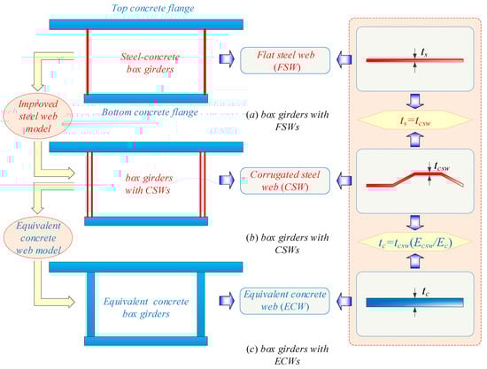
Figure 1.
Three different box girder models.
Based on the principle of equivalent stiffness, equivalent analysis models for box girders with equivalent concrete webs (ECWs), box girders with FSWs and box girders with CSWs have been established, which satisfy the following relationships: the thickness of FSW is equal to that of CSW, i.e., ts = tcsw, and the thickness expression of ECW satisfies the following equation tc = tcsw (Ecsw/Ec). Here, Ecsw and Ec are the Young’s elasticity moduli of CSWs and ECWs, respectively.
2.1. Box Girders with Flat Steel Webs
Box girders with FSWs (belonging to traditional steel–concrete composite box girders) are substitution models of box girders with ordinary concrete webs. They are simpler and easier to make than truss box girders. FSWs are often presented as forms of coffered flat webs (including vertical and longitudinal stiffeners attached by welding) in the practice of engineering, which could improve the stability of the webs, as shown in Figure 2b. The vertical stiffeners are mainly used to prevent the shear buckling and the stress concentration caused by the concentrated forces, while the longitudinal stiffeners are mainly used to prevent the buckling of the webs under the action of bending compressive stresses. When the thickness of stiffeners is smaller than the thickness of the web, the stiffeners bend, accompanied with an out-of-plane deformation of the web under the condition of instability. Accordingly, the stiffeners play an important role in increasing the stiffness of the web. When the thickness of stiffeners is larger than the thickness of the webs, the stiffeners could restrain the out-of-plane deformation of the web under buckling. So, in this case, there is no out-of-plane deformation on the stiffeners; thus, the stiffeners play a supporting role to the web.
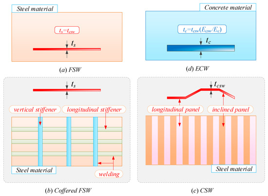
Figure 2.
Different web forms.
2.2. Box Girders with Corrugated Steel Webs
Box girders with CSWs own improved steel web models compared with box girders with FSWs. CSWs have a higher shear buckling strength than FSWs and are slightly more flexible in shear than FSWs [29]. Furthermore, compared with conventional FSWs, the difference in the cost of CSWs is small, as the welding steel stiffeners are eliminated, as shown in Figure 2c. So, CSWs can overcome the disadvantages of traditional welding-stiffened FSWs such as web instability due to fatigue, residual stress and normal stress. In addition, for box girders with CSWs, resistance to section distortion is higher and more uniform along the component compared with box girders with FSWs.
2.3. Equivalent Box Girders with Concrete Webs
Box girders with ECWs are equivalent box girder models to box girders with CSWs. These girders could be suggested using the MIDAS Civil 2020 v.3.1 software [30]. The large three-dimensional finite element software MIDAS Civil 2020 v.3.1 can be used to calculate the mechanical behaviour of box girders with CSWs by making corrugated webs equivalent to concrete webs.
3. Computational Models
In the following sections, the geometric parameters of the simplified models for the bridge application of box girders with CSWs are given. Considering the different material properties of concrete and steel, the finite element models are established. Combined with different working conditions, the finite element numerical calculations of box girders with CSWs are carried out.
3.1. Model Parameters
Box girders with CSWs are 36 m simply supported girders with a width of 12 m, a height of 2.5 m, a cantilever length of 3 m, a bottom concrete slab width of 6.4 m, a top concrete slab thickness of 300 mm and a bottom concrete slab thickness of 250 mm. The CSW has a web thickness of 9 mm, a corrugation height of 170 mm, a longitudinal panel length of 300 mm and a projected length of the inclined panel in relation to the longitudinal axis of 300 mm, as shown in Figure 3a.
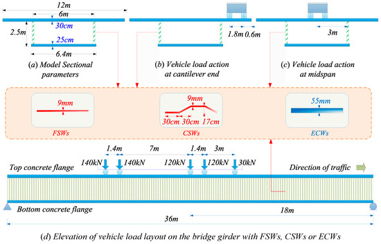
Figure 3.
Parameters and vehicle load layout of box girder models with CSWs.
3.2. Finite Element Models
In order to establish the transverse analysis models of the box girders with CSWs, finite element (FE) pre-processing of large finite element general software ANSYS 12.1 [31] has been considered. It is noteworthy that our chosen modelling methodology for the box girders has been rigorously validated through experimental verification in prior studies, ensuring the reliability of the finite element models [32,33,34]. Based on the creation of key points and lines, CSWs are established through vertical drag along an arbitrary vertical line. On the basis of surface creation, the upper and lower concrete slabs are obtained by a similar stretching technique. The three-dimensional (3D), eight-node solid element SOLID 45 was utilised to simulate the top and bottom slabs of box girders with CSWs, while the four-node shell element shell 63 was used to simulate the CSWs, as shown in Figure 4. The concrete slabs have a density set at 2500 kg/m3. In the elastic phase, the finite element model employs linear elastic constitutive relations, incorporating a concrete material elastic modulus of 34.5 GPa and a Poisson ratio of 0.2. The FSWs and CSWs are made of the same type of steel that have a density of 7850 kg/m3. The constitutive relation of the steel material is characterised as a linear elastic state, featuring a steel material elastic modulus of 210 GPa, a Poisson ratio of 0.3, and an acceleration of gravity of 9.8 m/s2. Considering that the models are in an elastic stage throughout, there will be no occurrence of interface relative slip between the concrete flanges and webs. Therefore, these parts are merged into a single instance with the main girder by Boolean operations, ensuring coordinated deformation and reliable connections.
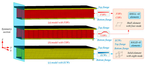
Figure 4.
Finite element models of box girders with different webs.
3.3. Load Case and Boundary Condition
In the analysis of the finite element models, the self-weight and the unfavourable vehicle load cases have been considered. Generally, the design of the concrete bridge deck is controlled by vehicle load. The five-axle load is used for the live load, and the total wheel load is 55 t [35]. Two load cases were set up, which correspond to different vehicle load positions. The most unfavourable load was arranged along the longitudinal direction, determined by the influence line of bending moments, as shown in Figure 3. The third wheel load of the vehicle act on the girder mid-span along the longitudinal direction. Translational displacements in all directions at both ends of girders were constrained to form simply supported girders, as shown in Figure 4.
3.4. Extraction Positions for Analysis
Currently, the unfavourable stress and deflection paths are extracted from ANSYS post-processing results. When the vehicle load is placed on the cantilever of the bridge deck, the transverse stress of Path B (the cantilever root) and the vertical deflection (deflection induced by longitudinal bending of the box girder is not included) of Path C (the cantilever end) are extracted. When the vehicle load is acting on the transverse mid-span of the bridge deck, the transverse tensile stress and vertical deflection of the adverse position (path A) are extracted at the same time. In the same way, the transverse stress and vertical deflection values under gravity action can be obtained. Considering the longitudinal symmetry section of box girders with CSWs, it can be seen that the mid-span path of the girders is Path A. Among them, Am, Bm and Cm are the middle points of paths A, B and C, respectively.
Under the action of self-weight and live load, the corresponding transverse stress of the path of the cantilever root represents the mechanical properties of the negative bending moment region near the web. The stress and deflection of the transverse mid-span path are used to represent the mechanical characteristics of the mid-span positive bending moment in the upper concrete flange, as shown in Figure 5.
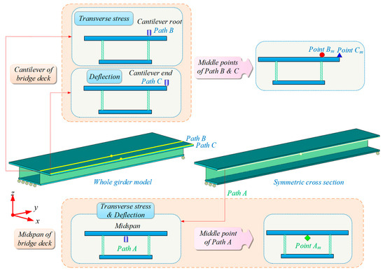
Figure 5.
Extraction positions of transverse stress and deflection of box girders with different webs.
4. Stiffness Comparison of Box Girders with Different Webs
Because there are differences among the web forms of the three considered typical box girders, there is a difference in the degree of constraint of the corresponding web to the bridge deck, and the stiffness contribution of webs will be different. Here, the conversion value of ECW thickness is 55 mm. The variation law of the transverse stress and deflection under the action of two kinds of loads (vehicle load and gravity) is discussed below.
4.1. Vehicle Load Action
As shown in Figure 6, under vehicle load action, the transverse tensile stress and deflection at the cantilever end and the mid-span of the box girders with CSWs are lower than those of the box girders with FSWs and the box girders with ECWs. Among them, the transverse stress and deflection values are similar at the cantilever end and mid-span of box girders with FSWs and with ECWs.
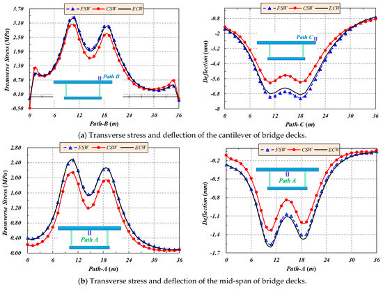
Figure 6.
Transverse stress and deflection of box girders with different webs under vehicle load action.
For the position of the transverse cantilever of box girders with CSWs, the transverse stress of the bridge deck below te vehicle rear axle is greater than that below the vehicle middle axle, but deflections of the two are similar. Relative to box girders with FSWs, the transverse stress of the bridge deck below the rear axle of box girders with CSWs is reduced by 10%; the reduction rate of the deflection of the bridge deck below the rear axle is 15.8%, while the transverse stress of the bridge deck below the middle axle of box girders with CSWs is reduced by 12.8% and the reduction rate of the deflection of the bridge deck below the middle axle is 17.9%.
For the position of the transverse mid-span of box girders with CSWs, the transverse stress and deflection of the bridge deck below the vehicle rear axle are greater than those below the vehicle middle axle. Relative to box girders with FSWs, the transverse stress of the bridge deck below the rear axle of box girders with CSWs is reduced by 13.5%, the reduction rate of the deflection of the bridge deck below the rear axle is 14.5%, the transverse stress of the bridge deck below the middle axle of box girders with CSWs is reduced by 13.8% and the reduction rate of the deflection of the bridge deck below the middle axle is 14.7%.
From the above situation, it can be found that under the vehicle load, compared with the FSWs and ECWs, CSWs can greatly reduce the transverse deflection of the free side of the cantilever slab and greatly reduce the transverse stress of the mid-span of the bridge deck.
4.2. Gravity Action
As shown in Figure 7, under gravity action, relative to box girders with FSWs and box girders with ECWs, CSWs can effectively reduce the tensile stress in the negative moment region and the vertical deflection at the cantilever end of the bridge deck. The transverse mid-span deflection of the bridge deck is also decreasing, and the amplitude of the stress in the middle span is relatively small, but has increased to a certain extent. Among them, the stress and deflection values on the bridge decks of box girders with FSWs and ECWs are close. Relative to box girders with FSWs, the transverse stress of the cantilever root of box girders with CSWs is reduced by 4.1%, and the deflection of the cantilever end of box girders with CSWs is reduced by 6.5%. In a similar manner, the transverse tensile stress in the middle span of box girders with CSWs is improved by 0.077 MPa, and the deflection of the mid-span of box girders with CSWs is reduced by 0.07 mm.
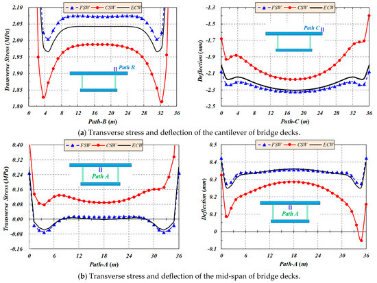
Figure 7.
Transverse stress and deflection of box girders with different webs under gravity action.
From the above discussion, it can be found that, under dead weight, the CSW can also effectively reduce the transverse deflection and stress of the free side of the cantilever slab. However, the absolute values of the deflection and stress of the mid-span of the bridge deck are very small on the whole.
5. Parametric Analysis of Box Girders with CSWs
In view of the condition of gravity action, the transverse stress and deflection in negative and positive moment zones of bridge decks of box girders with CSWs are analysed, respectively, which involves a series of corrugation parameters of CSWs. Additionally, these parameters are closely related to the stiffness of the corrugated web, and consequently they affect the transverse stress and deflection distribution of the bridge deck cantilever or mid-span of box girders with CSWs. In order to analyse the main factors (including corrugation height, web thickness, panel length, web height and elastic modulus) that affect the transverse stiffness, the transverse performance of box girders with CSWs is parameterised.
5.1. Transverse Stress and Deflection of the Cantilever (Paths B and C)
With the increase in the corrugation height of the box girders with CSWs, the transverse stress of Path B and the deflection of Path C decrease. When the corrugation height increases from 130 mm to 230 mm (with an increment of 20 mm), the transverse peak stress of Point Bm drops from 2.029 MPa to 1.913 Mpa, accompanied by a drop ratio of 5.72%, and the peak deflection of Point Cm decreases from 2.257 mm to 2.008 mm, with a drop ratio of 11.03%, as shown in Figure 8.

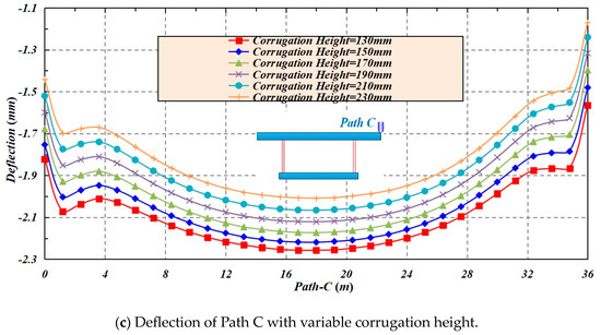
Figure 8.
The effect of corrugation height on the transverse stress and deflection of Paths B and C.
When the thickness of webs increases, the transverse stress of Path B and the deflection of Path C decrease. When the thickness of the webs increases from 8 mm to 22 mm (with an increment of 2 mm), the transverse peak stress of Point Bm drops from 1.996 MPa to 1.902 Mpa, accompanied by a drop ratio of 4.71%, and peak deflection of Point Cm decreases from 2.203 mm to 1.9128 mm, with a drop ratio of 13.17%, as shown in Figure 9.
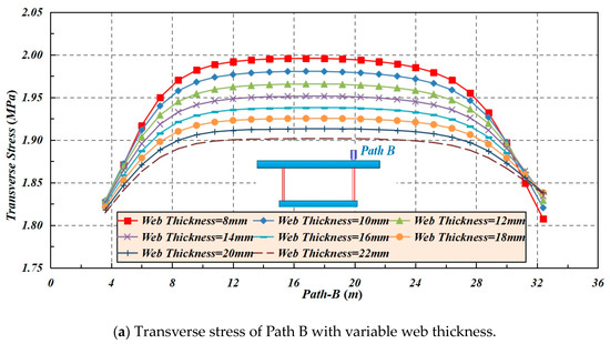
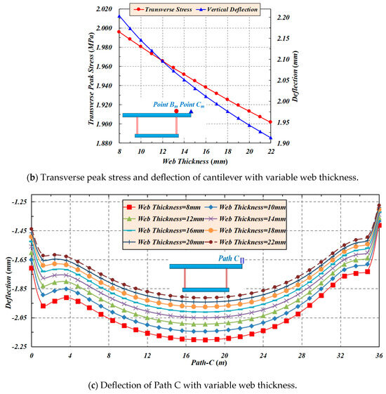
Figure 9.
The effect of web thickness on the transverse stress and deflection of Paths B and C.
With the increase in the panel segment length (length of longitudinal panel or projected length of inclined panel in relation to longitudinal axis) of the CSWs, the transverse stress of Path B increases, while the deflection of Path C decreases. Here, under the premise that the total length of box girders with CSWs is constant, the numbers of different panel segments of box girders with CSWs should be converted according to the variation in panel segment lengths. When the length of the longitudinal panel and projected length of the inclined panel in relation to the longitudinal axis (these two lengths are equal here) increase from 250 mm to 430 mm (with an increment of 30 mm), the transverse peak stress of Point Bm tends to increase from 1.9828 to 1.9972 MPa, accompanied by a growth rate of 0.73%, and the peak deflection of Point Cm tends to decrease from 2.182 to 2.142 mm, with a drop ratio of 1.83%, as shown in Figure 10.
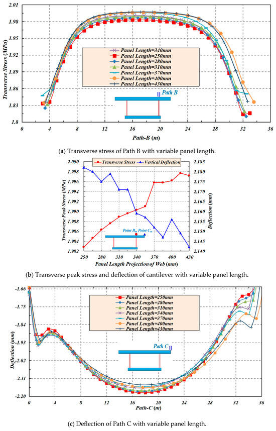
Figure 10.
The effect of panel length on the transverse stress and deflection of Paths B and C.
When the height of webs increases, both the transverse stress of path B and the deflection of Path C increase. When the height of webs increases from 2.2 m to 4.3 m (with an increment of 0.3 m), the transverse peak stress of Point Bm increases from 1.975 to 2.0195 MPa, accompanied by a growth rate of 2.25%, and the peak deflection of Point Cm increases from 2.173 to 2.1826 mm with a growth rate of 0.44%, as shown in Figure 11.
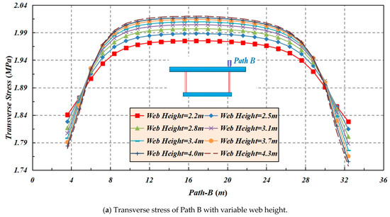
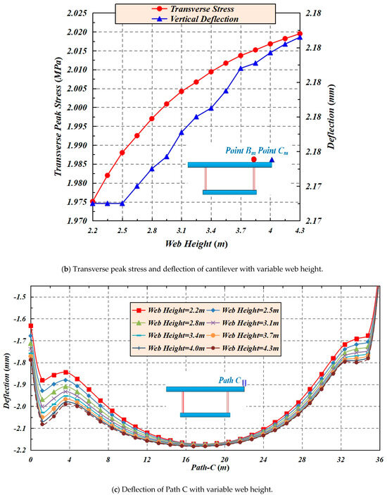
Figure 11.
The effect of web height on the transverse stress and deflection of Paths B and C.
With the increase in the modulus of elasticity of the webs, both the transverse stress of Path B and the deflection of Path C decrease. When the modulus of elasticity increases from 1.8 × 10⁵ MPa to 2.3 × 10⁵ MPa (with an increment of 0.1 × 10⁵ MPa), the transverse peak stress of Point Bm decreases from 1.9978 to 1.9815 MPa, accompanied by a drop ratio of 0.82%, and peak deflection of Point Cm decreases from 2.212 to 2.149 mm, with a drop ratio of 2.85%, as shown in Figure 12.

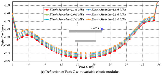
Figure 12.
The effect of elastic modulus on the transverse stress and deflection of Paths B and C.
As the stiffness of webs increases, the transverse stress of Path B and the deflection of Path C decrease. When the transverse peak stress of Point Bm decreases, the peak deflection of Point Cm decreases. It could also be observed that the rigidity of the panel segment has little effect on the improvement of the overall stiffness, while it is more sensitive to the transverse stress and deflection, as shown in Figure 13.
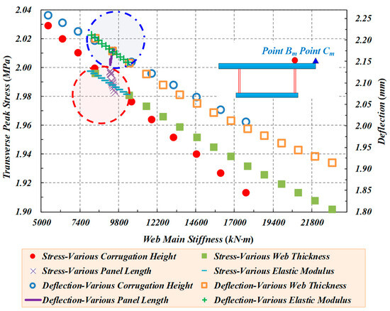
Figure 13.
The effect of web stiffness on the transverse stress and deflection of Points Bm and Cm.
From the above parametric analysis, for cantilever concrete slabs of box girders with CSWs, it can be found that under the effect of self-weight, both the corrugation height and the panel thickness have the greatest impact on transverse stress and deflection of bridge decks which can be reduced greatly by increasing the corrugation height and utilising thick enough panels of CSWs. In addition, the increase in panel width (inclined panel or longitudinal panel) and elastic modulus (high-strength steel material) can reduce the transverse deflection of cantilever slabs, to a certain extent. This is because the weight of webs has been reduced and the strength of webs has been improved. Moreover, utilising webs with larger depths can improve the transverse stress of the cantilever root of the top concrete slabs to a certain extent.
5.2. Transverse Stress and Deflection of the Mid-Span (Path A)
With the increase in corrugation height of the box girders with CSWs, the transverse stress of Path A increases, while the corresponding deflection decreases. When the corrugation height increases from 130 mm to 230 mm (with an increment of 20 mm), the transverse peak stress of Point Am increases from 0.04174 to 0.18728 MPa, accompanied by a growth of 0.14554 Mpa, and the corresponding deflection decreases from 0.327 to 0.206 mm, with a drop of 0.121 mm, as shown in Figure 14.
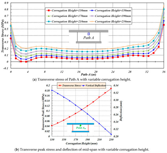
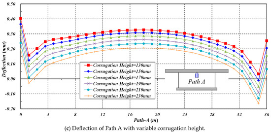
Figure 14.
The effect of corrugation height on the transverse stress and deflection of Path A.
With the increase in the web thickness, the transverse stress of Path A increases, while the corresponding deflection decreases. When the web thickness increases from 8 mm to 22 mm (with an increment of 2 mm), the transverse peak stress of Point Am increases from 0.07806 to 0.21174 MPa, accompanied by a growth of 0.13368 Mpa, and the corresponding deflection decreases from 0.299 to 0.1672 mm, with a drop of 0.1318 mm, as shown in Figure 15.
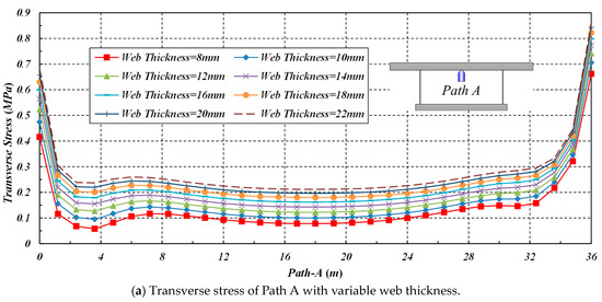
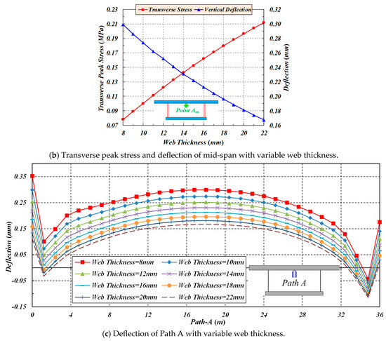
Figure 15.
The effect of web thickness on the transverse stress and deflection of Path A.
With the increase in the panel segment length of the CSWs, the transverse stress of Path A increases, while the corresponding deflection decreases. When the length of the longitudinal panel and the projected length of the inclined panel in relation to the longitudinal axis (which are alike in this investigation) increase from 250 mm to 430 mm (with an increment of 30 mm), the transverse peak stress of Point Am tends to increase from 0.08378 to 0.11014 MPa, accompanied by a growth rate of 0.02636 Mpa, and the corresponding peak deflection tends to decrease from the whole from 0.291 to 0.269 mm, with a drop of 0.022 mm, as shown in Figure 16.
Figure 16.
The effect of panel length on the transverse stress and deflection of Path A.
As the height of webs increases, the transverse stress of Path A decreases, while the corresponding deflection increases. When the web heights increase from 2.2 m to 4.3 m (with an increment of 0.3 m), the transverse peak stress of Point Am decreases from 0.11441 to 0.02035 MPa, accompanied by a drop of 0.09406 Mpa, and the corresponding deflection increases from 0.28 to 0.3076 mm with a growth of 0.0276 mm, as shown in Figure 17.

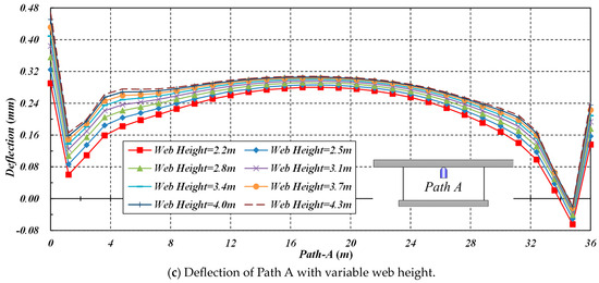
Figure 17.
The effect of web height on the transverse stress and deflection of Path A.
When the modulus of elasticity of CSWs increases, the transverse stress of Path A increases, while the corresponding deflection decreases. When the modulus of elasticity of webs increases from 1.8 × 10⁵ MPa to 2.3 × 10⁵ Mpa (with an increment of 0.1 × 10⁵ Mpa), the transverse peak stress of Point Am increases from 0.0751 to 0.09864 Mpa, accompanied by a growth of 0.02354 Mpa, and the corresponding deflection decreases from 0.303 to 0.275 mm, with a drop of 0.028 mm, as shown in Figure 18.
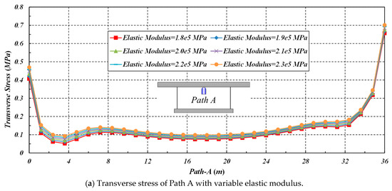
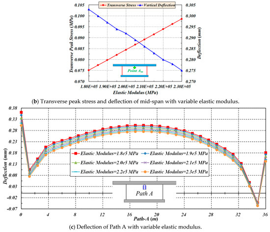
Figure 18.
The effect of elastic modulus on the transverse stress and deflection of Path A.
As the stiffness of the webs increases, the transverse stress of Path A increases, while the corresponding deflection decreases. When the transverse peak stress of Point Am increases, the corresponding peak deflection decreases. The rigidity of the panel segment has little effect on the improvement of the overall stiffness, as shown in Figure 19.
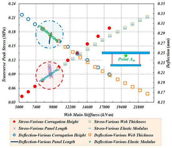
Figure 19.
The effect of web stiffness on the transverse stress and deflection of Point Am.
From the above parametric analysis, for mid-span concrete slabs of box girders with CSWs, it can be found that under the effect of self-weight, the corrugation height and the panel thickness have, to some extent, an impact on the transverse stress and deflection. Additionally, webs with large depths have a certain effect on the transverse stress of top concrete slabs.
6. Stiffness Analysis of Box Girders with CSWs
The equivalent flexural stiffness of the CSWs in x-direction per unit length for box girder bridges, involving many corrugation waves with the dimensions shown in Figure 20, can be calculated as:
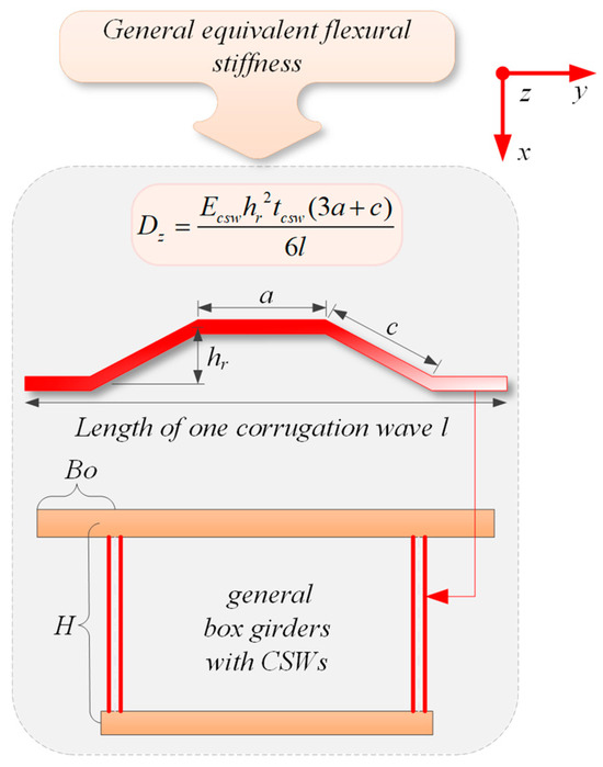
Figure 20.
Equivalent flexural stiffness of CSWs for box girders.
The above formula shows that the stiffness of the CSWs is closely related to Young’s modulus Ecsw of steel material, corrugation height hr, web thickness tcsw and panel segments lengths (longitudinal panel length a and inclined panel length c). Among them, l represents the projected length of the total folded panel segments of single periodic corrugation in relation to the longitudinal axis:
These factors are also fully reflected in the current analyses. However, it has been found that the dimensions of the CSWs have a certain influence on the stiffness, and they can be included in a new stiffness formula in the future to obtain better stiffness predictions for the CSWs. Among them, the most influential parameters are the corrugation height and the web thickness. Additionally, the tensile stress is particularly important for the bridge deck due to the direct contact wheel load, almost included in the transverse stress of box girders with CSWs. Thus, it affects the bearing capacity of concrete bridge deck slabs. Although corrugation height and panel thickness have a great influence on both the transverse stress and deflection of the top concrete flanges of box girders with CSWs (including the cantilever and mid-span), the web height also has a certain effect on the transverse stress. So, the effect of panel segments’ lengths and the modulus of elasticity on the transverse deflection of cantilever slabs cannot be ignored.
7. Conclusions
In this paper, the characteristics and differences of box girders with CSWs were interpreted from the development history of the web forms of box girders, and the transverse performance of box girders with three different webs (including box girders with ECWs, box girders with FSWs and box girders with CSWs) were compared. Then the influence of a series of web parameters on the transverse performance of box girders with CSWs was analysed, and the factors that greatly influence the stiffness of box girders with CSWs (or not be ignored) were obtained.
- (1)
- Based on the gradual improvement and evolution of three typical box girders, the equivalent analytical models between box girders with ECWs, box girders with FSWs and box girders with CSWs were established using the principle of equivalent stiffness. In this study, the effect of web stiffness on the transverse stress distribution and the differences of web constraints on the bridge deck were given. The results of this work can be used as a reference for analysing and designing similar projects.
- (2)
- Because the web constraint degree and stiffness contribution to the top concrete flange slabs of box girders with the three different typical webs are different, their effects on the transverse stress distribution and deflection of the bridge deck under vehicle load and dead weight were studied. Compared with FSWs and ECWs, CSWs can greatly reduce the transverse deflection of the cantilever end of the bridge deck and the transverse stress in the mid-span under the vehicle load. Under the action of gravity, CSWs can effectively reduce transverse deflection and stress at the free ends of cantilever slabs. Additionally, the transverse deflection and stress of the mid-span of the bridge deck become relatively small using the CSWs.
- (3)
- By considering the influence of the corrugation size, the transverse performance of the cantilever and mid-span of the box girder bridge deck was analysed, which is beneficial to the optimisation of the transverse design. By changing the corrugation size, the transverse parametric analysis of box girders with CSWs was carried out. Under the condition of gravity, it was found that the corrugation height and web thickness can significantly reduce the transverse stress and deflection. Moreover, increasing the panel width and elastic modulus can reduce the transverse deflection of the cantilever end to a certain extent. Therefore, it is necessary to increase the panel width if the corrugation height remains unchanged and to utilise high-strength steel webs. The results also showed that using webs with larger depths can improve the transverse stress of the cantilever root of the bridge deck to some extent, and has a certain effect on the transverse stress of the mid-span of deck slabs.
- (4)
- In the stiffness analysis of the box girders with CSWs, it was found that the web height has some influence on stiffness, while the corrugation height and the web thickness have a great influence on the stiffness. It was finally suggested that a new stiffness formula should be developed for box girders with CSWs. At the same time, the influence of panel segments and high-strength steel on the transverse deflection of cantilevered plates should not be neglected.
Author Contributions
Conceptualization, M.Z.; Methodology, F.X.; Software, F.X.; Validation, K.W.; Formal analysis, Y.C.; Investigation, Y.C.; Resources, Y.C.; Data curation, F.X.; Writing—original draft, F.X.; Writing—review & editing, M.Z.; Visualization, K.W.; Supervision, K.W.; Funding acquisition, M.Z. All authors have read and agreed to the published version of the manuscript.
Funding
This study is supported by the National Natural Science Foundation of China under Grant number 52278209 and the Fundamental Research Funds for the Central Universities under Grant number 2042023kf0171.
Data Availability Statement
The data presented in this study are available on request from the corresponding author.
Conflicts of Interest
The authors declare no conflicts of interest.
Nomenclature
| ts | the thickness of FSWs |
| tcsw | the thickness of CSWs |
| tc | the thickness of ECWs |
| Ecsw | the Young’s elasticity moduli of CSWs |
| Ec | the Young’s elasticity moduli of ECWs |
| Dy | the equivalent flexural stiffness of CSWs in y-direction per unit length |
| hr | corrugation height |
| a | longitudinal panel length |
| c | inclined panel length |
| l | the projection length of total folded panel lengths of single periodic corrugation in relation to the longitudinal axis |
References
- Deng, W.; Zhou, M.; Hassanein, M.F.; Zhang, J.; Liu, D.; An, L. Growth of prestressed concrete bridges with corrugated steel webs in China. Proc. Inst. Civ. Eng. Civ. Eng. 2018, 171, 77–84. [Google Scholar] [CrossRef]
- Aggarwal, K.; Wu, S.; Papangelis, J. Finite element analysis of local shear buckling in corrugated web beams. Eng. Struct. 2018, 162, 37–50. [Google Scholar] [CrossRef]
- Guo, T.; Sause, R. Analysis of local elastic shear buckling of trapezoidal corrugated steel webs. J. Constr. Steel Res. 2014, 102, 59–71. [Google Scholar] [CrossRef]
- Yi, J.; Gil, H.; Youm, K.; Lee, H. Interactive shear buckling behavior of trapezoidally corrugated steel webs. Eng. Struct. 2008, 30, 1659–1666. [Google Scholar] [CrossRef]
- Easley, J.T. Buckling Formulas for Corrugated Metal Shear Diaphragms. J. Struct. Div. 1975, 101, 1403–1417. [Google Scholar] [CrossRef]
- Hassanein, M.F.; Kharoob, O.F. Shear buckling behavior of tapered bridge girders with steel corrugated webs. Eng. Struct. 2014, 74, 157–169. [Google Scholar] [CrossRef]
- Hassanein, M.F.; Elkawas, A.A.; El Hadidy, A.M.; Elchalakani, M. Shear analysis and design of high-strength steel corrugated web girders for bridge design. Eng. Struct. 2017, 146, 18–33. [Google Scholar] [CrossRef]
- Zhou, M.; Zhang, J.; Zhong, J.; Zhao, Y. Shear Stress Calculation and Distribution in Variable Cross Sections of Box Girders with Corrugated Steel Webs. J. Struct. Eng. 2016, 142, 04016022. [Google Scholar] [CrossRef]
- Elkawas, A.A.; Hassanein, M.F.; Elchalakani, M. Lateral-torsional buckling strength and behaviour of high-strength steel corrugated web girders for bridge construction. Thin-Walled Struct. 2018, 122, 112–123. [Google Scholar] [CrossRef]
- Guo, J.Q.; Zheng, Z. Analysis of transverse internal forces in box girder bridges with cantilevers. China Civ. Eng. J. 1986, 19, 59–72. [Google Scholar]
- Zheng, H.; Liu, Z. Discussion on the reasonable structural forms of wide box girder. In Proceedings of the 15th National Conference on Bridge Engineering, Dalian, China, 22 August 2013; Volume 25–29. [Google Scholar]
- Zhou, M.; Zhang, J.; Yang, D.; Hassanein, M.F.; An, L. Transverse Analysis of a Prestressed Concrete Wide Box Girder with Stiffened Ribs. J. Bridge Eng. 2017, 22, 04017046. [Google Scholar] [CrossRef]
- Shushkewich, K. The Strutted Box Widening Method for Prestressed Concrete Segmental Bridges. PCI J. 2003, 48, 64–81. [Google Scholar] [CrossRef][Green Version]
- Shushkewich, K.W. Design of Prestressed Concrete Bridges to Accommodate Future Widening. PCI J. 2005, 50, 74–89. [Google Scholar] [CrossRef]
- Shushkewich, K.W. Transverse Analysis of Strutted Box Girder Bridges. J. Bridge Eng. 2006, 11, 33–47. [Google Scholar] [CrossRef]
- Collings, D.; Sagaseta, J. A review of arching and compressive membrane action in concrete bridges. Proc. Inst. Civ. Eng. Bridge Eng. 2016, 169, 271–284. [Google Scholar] [CrossRef]
- Zaid, A.; Collings, D. Transverse assessment of a concrete box girder bridge. Proc. Inst. Civ. Eng. Bridge Eng. 2017, 170, 14–27. [Google Scholar] [CrossRef]
- Choi, Y.C.; Oh, B.H. Transverse Modeling of Concrete Box-Girder Bridges for Prediction of Deck Slab Ultimate Load Capacity. J. Bridge Eng. 2013, 18, 1373–1382. [Google Scholar] [CrossRef]
- Kurian, B.; Menon, D. Correction of Errors in Simplified Transverse Bending Analysis of Concrete Box-Girder Bridges. J. Bridge Eng. 2005, 10, 650–657. [Google Scholar] [CrossRef]
- Kurian, B.; Menon, D. Transverse bending analysis of concrete box-girder bridges with flange overhangs. J. Struct. Eng. 2008, 35, 173–179. [Google Scholar]
- Maguire, M.; Moen, C.D.; Roberts-Wollmann, C.; Cousins, T. Field Verification of Simplified Analysis Procedures for Segmental Concrete Bridges. J. Struct. Eng. 2015, 141, D4014007. [Google Scholar] [CrossRef]
- Recupero, A.; Granata, M.F.; Culotta, G.; Arici, M. Interaction between Longitudinal Shear and Transverse Bending in Prestressed Concrete Box Girders. J. Bridge Eng. 2017, 22, 04016107. [Google Scholar] [CrossRef]
- Peng, K.; Li, L.; Wang, W. Experimental study on effective distribution width of transverse load of composite box girder with corrugated steel webs. J. China Foreign Highw. 2009, 29, 164–167. [Google Scholar]
- Yuan, Z.; Li, L.; Liu, Q.; Hou, J. Analysis and experimental study of transverse internal force in composite box-girder with corrugated steel webs. China J. Highw. Transp. 2015, 28, 73–81. [Google Scholar]
- Zhao, P.; Ye, J. Analysis of transverse internal force in deck of box girder with corrugated steel webs under wheel load. J. Highw. Transp. Res. Dev. 2013, 30, 44–48. [Google Scholar]
- Zhao, P.; Rong, X.; Ye, J. Research on the lateral effective width of composite box-girders with corrugated steel webs. J. Highw. Transp. Res. Dev. 2016, 43, 105–110. [Google Scholar]
- Jia, H.; Dai, H.; Zhang, J. Research on transverse internal forces in box-girder bridges with corrugated steel webs. Eng. Mech. 2014, 31, 76–82. [Google Scholar]
- Li, Y.; Yang, B.; Zhang, J. Transverse moment of PC single box-girder bridge with corrugated steel webs. J. Cent. South Univ. Sci. Technol. 2016, 47, 2802–2809. [Google Scholar]
- Sayed-Ahmed, E.Y. Behaviour of steel and (or) composite girders with corrugated steel webs. Can. J. Civ. Eng. 2001, 28, 656–672. [Google Scholar] [CrossRef]
- MIDAS Civil. MIDAS Structural Analysis; MIDAS Information Technology Co., Ltd.: Seongnam, Republic of Korea, 2012. [Google Scholar]
- ANSYS 12.1. User’s Manual Revision; ANSYS, Inc.: Canonsburg, PA, USA, 2012. [Google Scholar]
- Zhou, M.; Liao, J.; An, L. Shear properties of tapered box girders with steel trapezoidally corrugated webs considering Resal effect. ASCE J. Bridge Eng. 2020, 25, 04019126. [Google Scholar] [CrossRef]
- Zhou, M.; An, L. Full-range shear behavior of a nonprismatic beam with trapezoidally corrugated steel webs: Experimental tests and FE modeling. ASCE J. Struct. Eng. 2020, 146, 04020162. [Google Scholar] [CrossRef]
- Zhou, M.; Fu, Y.; Su, L.; An, L. Shear performance analysis of a tapered beam with trapezoidally corrugated steel webs considering the Resal effect. Eng. Struct. 2019, 196, 109295. [Google Scholar] [CrossRef]
- Ministry of Communications of the People’s Republic of China. General Specifications for Design of Highway Bridges and Culverts; JTG D60-2015; China Communication Press: Beijing, China, 2015. [Google Scholar]
Disclaimer/Publisher’s Note: The statements, opinions and data contained in all publications are solely those of the individual author(s) and contributor(s) and not of MDPI and/or the editor(s). MDPI and/or the editor(s) disclaim responsibility for any injury to people or property resulting from any ideas, methods, instructions or products referred to in the content. |
© 2024 by the authors. Licensee MDPI, Basel, Switzerland. This article is an open access article distributed under the terms and conditions of the Creative Commons Attribution (CC BY) license (https://creativecommons.org/licenses/by/4.0/).