1. Introduction
The building sector has attracted global attention as a significant contributor to energy-related issues, accounting for 40% of worldwide energy consumption [
1] and approximately 30% of total greenhouse gas emissions [
2]. In this regard, the refurbishment of existing buildings will play a crucial role in achieving energy and climate objectives outlined in the European Union (EU) Sustainable Development Goals (SDGs) for Agenda 2030 [
3], given that 35% of the European Union’s buildings are over 50 years old and about 75% of the building stock is considered energy inefficient [
4]. Accordingly, there is an urgent need to refurbish and retrofit old and energy-inefficient buildings and find effective solutions to enhance thermal and energy performance, thereby reducing overall energy consumption [
5].
One potential strategy to tackle this challenge involves the use of thermal energy storage (TES) systems incorporating phase change materials (PCMs) since they provide an effective means of mitigating indoor temperature fluctuations and energy demands [
6]. These materials, with a designated melting and crystallization temperature range, demonstrate the capacity to store and release thermal energy upon demand [
7]. Essentially, energy is stored in a latent form during the transition from a solid to a liquid state, and during the reverse process (i.e., from a liquid to a solid state), the stored energy is released [
8]. Notably, the U.S. Department of Energy (DOE) has recognized the use of PCMs as the system most capable of thermal latent heat storage in passive solar designs [
9]. Due to their promising capabilities, PCMs have been extensively researched for innovative applications in buildings in recent years, including mortars and concrete [
8,
10,
11,
12,
13], masonry technologies and bricks [
14,
15], plastic foams [
16], gypsum boards [
17,
18], and passive solar applications [
19,
20]. The integration of PCMs into building materials or systems offers a promising means of mitigating indoor temperature fluctuations, thereby enhancing overall energy efficiency. Notably, the study by Christen et al. [
10] demonstrated a significant reduction in maximum indoor temperatures, by up to 3.9 °C, achieved through the use of 3D-printed concrete with PCM incorporated via vacuum impregnation. Likewise, Mahdaoui et al. [
15] explored the application of a hollow building brick with microencapsulated PCM, achieving a 2 °C reduction in daily thermal amplitude. Similar positive outcomes were observed in the studies of gypsum boards modified with microencapsulated PCM [
18] and a Trombe wall system enhanced with macroencapsulated PCM [
20,
21].
Nevertheless, applications of PCM in refurbishment remain a relatively unexplored research domain, marked by a scarcity of studies on the matter, especially those adopting an experimental approach. Experimental tests play a crucial role in this field, allowing for the consideration of real conditions in thermal performance analysis. In this context, novel approaches for deriving environmental and energy parameters in building monitoring are making the process more accessible and accurate [
22]. One of the pioneering investigations on using PCM to enhance building envelope refurbishment was conducted by Ascione et al. [
23] in Italy in 2014, employing simulation analysis. Their findings revealed a reduction in cooling season energy demand with an increase in the thickness of the PCM wallboard. Moreover, a collection of additional studies and review papers addressing the retrofit of new and existing buildings is available in the literature [
24,
25,
26,
27,
28,
29,
30,
31,
32,
33,
34]. In a more recent study, Imafidon and Ting [
28] investigated the potential energy savings achieved by incorporating a layer of honeycomb PCM wallboard into the wall assembly of a prefabricated retrofit panel across various climates. Their simulation-based investigation concluded that optimal performance was achieved when the PCM layer was positioned closer to the indoor environment than the outdoors, resulting in a 13% reduction in heat loss and an 8% reduction in heat gain. Regarding experimental research, Berardi and Soudian [
26] examined a composite PCM system with varying melting temperatures, evaluating its influence on indoor air and surface building temperatures through monitoring conducted in two test cells. Their findings indicated a notable reduction in peak indoor and surface temperatures, with decreases of up to 6 °C.
Now, addressing the identified gap in the literature involves incorporating solutions containing PCM into real-scale construction applications. To do so, in this study, we set out to introduce and investigate a novel constructive solution: a PCM containing mortar for a flooring application, to compensate for the thermal inertia losses caused by the use of thermal insulation materials in the inner surface of the building’s envelope. This scenario arises as a result of building refurbishment since national laws often require the preservation of the historical appearance, limiting the interventions that can be applied to the inner layer of exterior walls. Given that thermal comfort and energy efficiency are the paramount objectives when applying this innovative solution, real-condition experimental monitoring, complemented by a dynamic thermal simulation of a real-scale test cell, was carried out to analyze its performance.
2. Methodology
The main goal of this work was the development of and research into a novel constructive solution incorporating PCM for new or refurbished buildings, and thermal comfort and energy efficiency were the two main goals we considered. In this context, monitoring and dynamic thermal simulation of a test cell using EnergyPlus
® (EnergyPlus is funded by the U.S. Department of Energy’s (DOE) Building Technologies Office (BTO), and managed by the National Renewable Energy Laboratory (NREL)) [
35] were carried out to evaluate whether those goals were achieved.
Our methodology began with the development of an experimental setup of a test cell that could be used for real thermal characterization, as well as the validation of the numerical model. To record the values of temperatures and relative humidity (RH), thermo-hygrometer sensors were installed. The sensors were positioned inside the test cell in such a way as to avoid direct sun exposure through its glazed area, following the recommendations of the standard ISO 7726 [
36].
To determine the passive solar building thermal performance using a test cell as a demonstrator, the novel developed PCM constructive solution was evaluated following the methodology depicted in
Figure 1.
This methodology was divided into five main steps.
The first step was the experimental preparation and setup, where the slabs were produced from an expanded clay containing mortar with PCM (developed by Salgueiro et al. [
37] in a previous study) for subsequent application on the floor of one test cell compartment.
The second step involved the characterization of the test cell (dimensions, orientation, and constructive solutions). In this step, to characterize the constructive solution (namely, slab boards), the transient plane source (TPS) method and a modulated differential scanning calorimeter (MDSC) were used.
The third step was the experimental tests, where the selected parameters were recorded using a data acquisition system. To do so, the outdoor parameters—relative humidity (RH), solar radiation (S) and air temperature (Tair)—were monitored with local weather data. Regarding the indoor environment’s conditions: air temperature, relativity humidity and heat flows were monitored. Data acquisition was carried out with a time step of 10 min for a period of approximately one month.
The fourth step focused on the numerical simulation of the building’s thermal performance, using Energy+®, where the experimental setup data of the previous step were used for calibration purposes. In this step, the fitness between the real and simulated data was evaluated for the model calibration. Then, the ventilation rate of the test cell was improved to mitigate overheating, using the total latent heat capacity of the PCM.
In the fifth and last step, the data obtained through experimental test monitoring and numerical simulations were analyzed, evaluated, and discussed.
3. Case Study
3.1. Base Model: General Setup
The test cell is located at the University of Aveiro, Aveiro, Portugal. This test cell is divided into two identical compartments, without any shading system installed or mechanical/natural ventilation devices/grids (
Figure 2). The glazed wall of the test cell faces due south, allowing for the maximization of passive solar gains [
9]. As shown in
Figure 2a, one of the compartments of the test cell was used as the reference compartment (C-REF) while slabs with PCM were placed in the other compartment (C-PCM).
The test cell structure has the shape of a rectangular parallelepiped (
Figure 2b) and measures 7 m × 2.35 m × 2.57 m (L × W × H), which represents a total floor area of 16.45 m
2 and an internal volume of each compartment of 21.14 m
3.
Regarding the constructive solutions, the floor structure is composed of structural metal profiles and 18 mm of insulation material with a thermal conductivity of 0.30 W m−2 K−1 and vinyl finish. The external walls of the test cell are composed of 40 mm sandwich panels (with polyurethane foam as the insulation material), and the roof is also composed of sandwich panels with two additional layers of glass fiber and water vapor protection. The total thickness is equal to 80 mm.
As previously indicated, the test cell is divided into two internal compartments, which are separated by an internal partition wall composed of a sandwich panel with 40 mm of insulation material. Furthermore, to improve the thermal insulation and to reduce the energy transfer between compartments, for this study, an additional layer was applied on each partition wall surface containing 40 mm of XPS insulation material.
The front south façade is composed of four panes of double-glazed windows with air between the layers (5 + 12 + 5 mm), with an area of 1.80 × 2.28 m2.
3.2. Slab Boards’ Production
In the experimental work, the mixture used for the slab board production was that put forward by Salgueiro et al. [
38], which was developed following the European Standard EN 998–1 [
39], which is specific for plaster mortars.
Furthermore, the mortar was formulated according to NP EN 197–1 [
40], composed of Portland cement (Type I, Class 42.5R (Cimpor) [
41]), water, Leca
® XS and microencapsulated PCM.
The microencapsulated PCM added to the mortar mixture was
Micronal DS 5040 X. This is a powder that contains a paraffin wax core wrapped inside polymeric microcapsules with sizes ranging from 50 μm to 300 μm. The
Micronal characteristics are shown in
Table 1.
The slabs’ fabrication started with mixing the mortar in accordance with the mixture formulation presented in
Table 2, following the procedure defined in NP EN 196–1 [
43] to ensure homogeneity of all mortar aggregates.
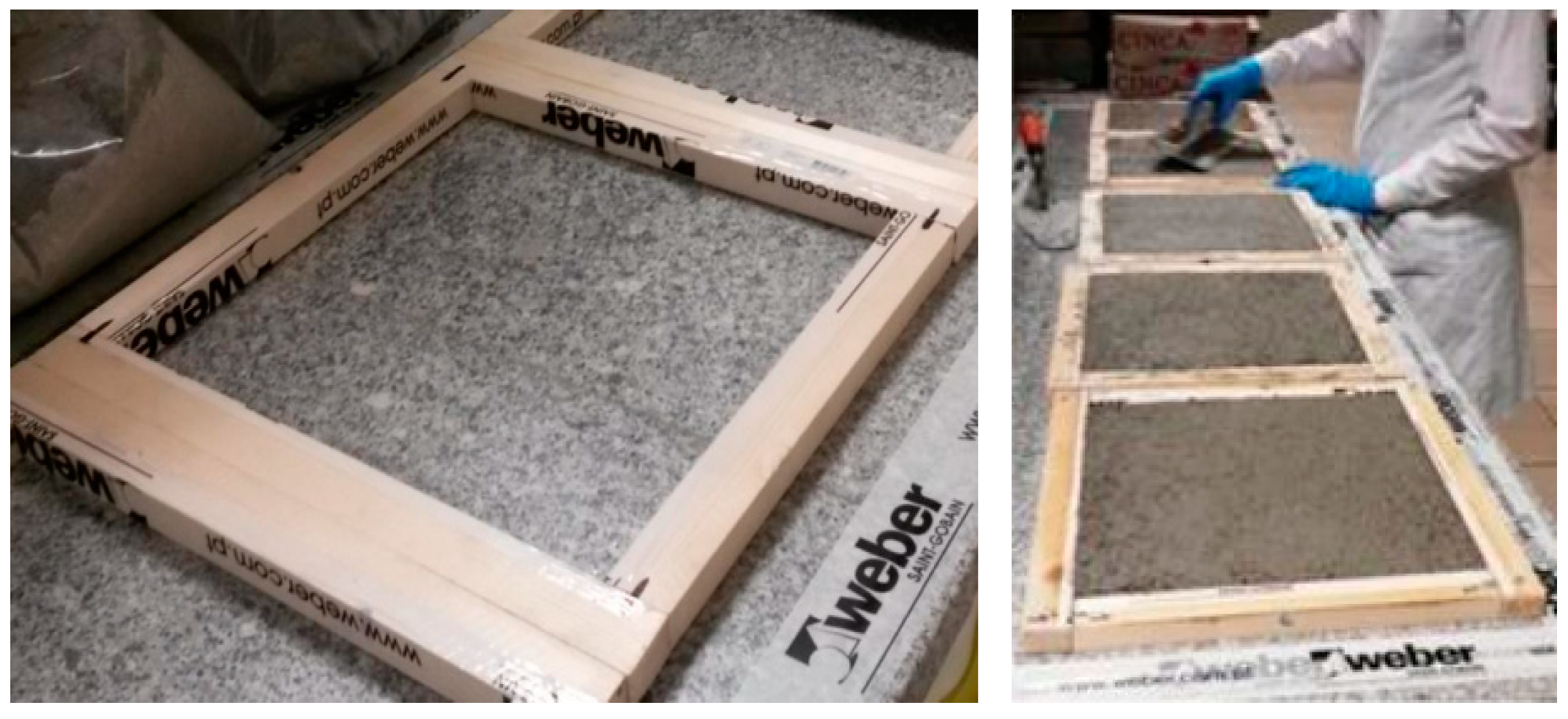
After the mixing process, the mixture was immediately moved to the casts, which have a parallelepiped shape (0.30 × 0.30 × 0.02 m
3), as presented in
Figure 3.
The boards were left inside the molds for 48 h, with the curing process performed in a laboratory at 23 ± 2 °C and 50 ± 5% relative humidity.
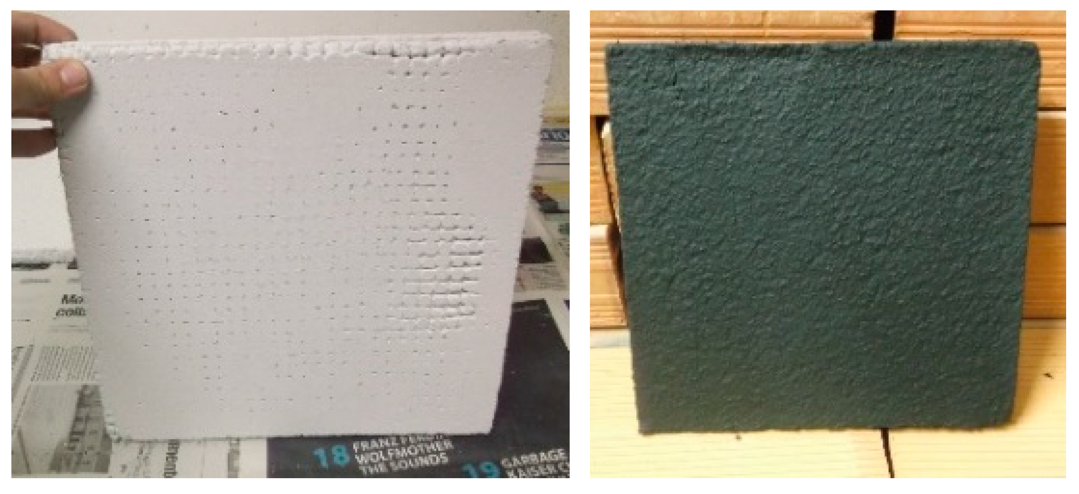
After the curing process was finished, all slabs were painted with black matte paint (
Figure 4) to maximize solar absorption. Additional information on the characterization of the slab boards can be found by consulting the studies conducted by Salgueiro et al. [
44], Monteiro [
45] and Nunes [
46]. To construct the test cell with PCM slabs covering the entire floor, a total of 39 kg of PCM and 172 kg of mortar were utilized.
3.3. Slab Boards’ Thermal Characterization
The mortar used for the board’s fabrication was thermally characterized using the following approaches:
TPS (transient plane source) method using the
Hot Disk AB TPS 2500 S equipment. In this method, a designated amount of heat is introduced through a sensor positioned between two specimens of the same material. The specimen absorbs this heat, and by assessing the energy released to the surroundings, the values for thermal conductivity and specific heat capacity are estimated [
47];
MDSC (modulated differential scanning calorimeter) method using the
TA Instruments Q100 equipment. In this test, a temperature increment is applied to both the specimen and a reference material, while sensors gauge the temperature difference between them. During a phase change in the specimen, the heat flux as a function of temperature is quantified [
48].
A full description of the mortar thermal properties is presented in Salgueiro et al.’s work [
38]. The most important mortar properties for this work are presented in
Table 3.
The enthalpy evolution of the mortar containing PCM was experimentally measured by the MDSC method and evaluated by the mathematical integration of the specific heat as a function of the temperature (
Figure 5).
As expected, the mortar’s measured enthalpy was lower than the values of the microencapsulated PCM. These results validated the values given by the manufacturer, with the heat of fusion reduced by 74% (from 95 kJ kg−1 to 25 kJ kg−1), which was equivalent to the PCM quantity in the mortar mixture.
3.4. Numerical Modeling: Monitoring and Validation
Computational models are becoming increasingly prevalent in various fields of science and engineering. These models are developed to predict and understand complex phenomena that are difficult or impossible to observe experimentally. However, the accuracy of these models depends on how well they can represent a real-world system. Therefore, validating numerical models is crucial for ensuring the accuracy and reliability of their results.
The hygrothermal and heat flow of the test cell were monitored, as well as the weather data (solar radiation, S, air temperature, Tair, and relative humidity, RH). These data are fundamental for the numerical model’s calibration and validation.
For the external monitoring (weather data), a pyranometer (
LP PYRA 03) was used to measure and record the global radiation (W m
−2) in compliance with the ISO 9060 standard [
49] and meet the requirements defined by the Word Meteorological Organization (WMO). This pyranometer is designed to support extreme climatic conditions and was installed on the roof of the test cell.
The measurements of the outdoor air temperature and relative humidity were carried out using an HD 9008 TR hygrothermal device, which has a capacitive humidity sensor of type H6100 and a Pt100 temperature sensor. This device was installed on the roof and protected against the wind, solar radiation, and rain by a ring-type Delta Ohm.
For indoor monitoring, to record the temperature and relative humidity, thermo-hygrometer sensors were used (JUMO 907021/21): the temperature probe has an accuracy of 0.5 °C and a resolution of 0.1 °C, and the humidity probe has 3% RH accuracy and 0.1% RH resolution. The temperature was also monitored by Pt100 probes.
The internal heat flow through both internal compartments was measured and recorded using a Hukseflux HFP01 thermal flow meter. This has a ceramic–plastic body that keeps the thermal resistance low. Considering the temperature dependence, over the temperature range from −30 °C to 70 °C, the heat flux uncertainty was ±5%.
Figure 6 shows the locations of internal and external probes used in this experimental test.
The test cell was monitored for almost one month (from 23 September to 9 October). Sensors were positioned inside the test cell in order to avoid direct sun exposure through the glazed area. Furthermore, this distribution was in accordance with ISO 7726 [
36], which serves to prevent the combined effect of solar radiation and exterior temperature of exterior walls.
3.5. Weather Files Used for Numerical Models
In accordance with the World Map of Köppen—Geiger Climate Classification, Aveiro is located in a Csa region (C—warm temperature; s—summer dry; a—hot summer). In terms of a detailed weather classification, to correspond with the parameters in the simulations, the climatic database from LNEG (National Laboratory for Energy and Geology) was used.
A summary of the weather data adopted for the simulation is shown in
Table 4, where the average monthly values of the air temperature, relative humidity, direct normal irradiance (DNI), and diffuse horizontal irradiance (DHI) are presented.
To characterize the weather, the hottest months and those with higher irradiance are July and August; meanwhile, the lowest temperatures occur in December, January, and February, which also present the higher values of relative humidity.
3.6. Numerical Model Definition
In this sub-section, the model features of the whole dynamic building simulation are presented, which were developed to simulate the thermal and energy behavior of the case study. The model was created using SketchUp® with the OpenStudio® plugin, to reproduce the geometry of the case study. The numerical calculations were carried out using the Energy+® software.
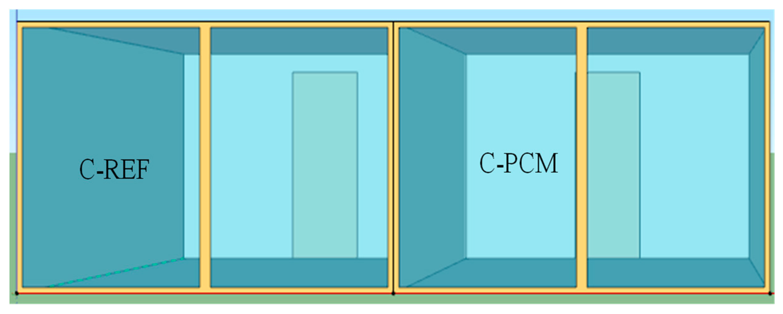
A multi-zone model with two thermal zones was considered, which corresponded to the internal compartments (spaces with and without slab board containing PCM) of the test cell (see
Figure 7). Both zones had the same indoor space and geometry, orientation, opaque constructive solutions, and glazed area, enabling them to be compared. As presented in
Section 3.1, one of the compartments had PCM boards installed in the floor (C-PCM), and the other compartment without PCM was considered the reference compartment (C-REF) (
Figure 7).
The test cell was simulated without considering human occupation or heating sources (lighting, electric equipment, and active systems for heating or cooling) to represent completely passive use.
4. Results’ Analyses and Discussion
4.1. Test Cell’s Performance (Real Data)
To achieve the main objective of the present research work, it was essential for us to evaluate and compare the thermal behaviors of the novel constructive solution containing PCM and the reference solution, both when applied under real environmental conditions.
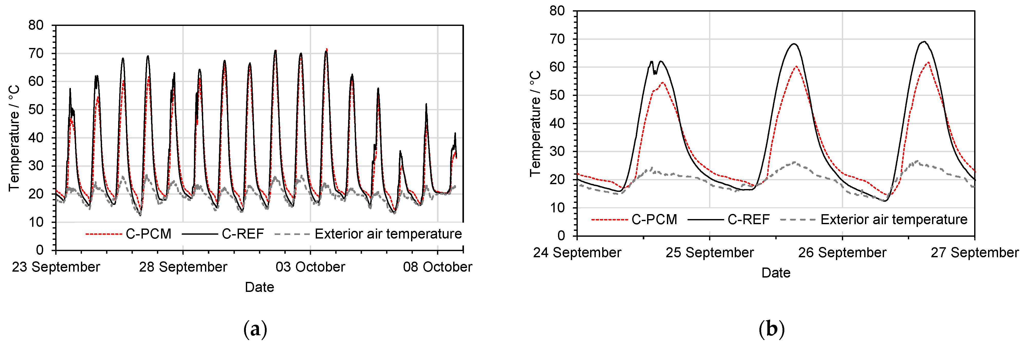
Figure 8 shows the indoor temperature measured in both compartments, where C-REF corresponds to the air temperature of the reference compartment and C-PCM corresponds to the air temperature of the PCM compartment.
When analyzing these results, the compartment with the PCM solution presents the following:
Thermal amplitude reduction of 21% (average);
Longer time delay, of between 60 min to 90 min, to reach the maximum and minimum indoor temperatures;
Lower maximum air temperature peak (average of 13%);
Higher minimum air temperature peak (average of 14%).
During the day, the PCM prevented high overheating values, and during the night, it contributes to preventing an excessive temperature drop. Despite periods of excessive overheating, as well as extreme indoor air temperatures in both compartments, the reference compartment showed a higher temperature amplitude.
During the night, the PCM compartment present higher minimum indoor air temperatures and also a longer time delay to reach the minimum temperature.
Both compartments have large south-facing glazed areas, meaning they are strongly influenced by solar radiation, which significantly increases the indoor air temperatures.
4.2. Dynamic Building Simulation
4.2.1. Numerical Model’s Validation
The numerical model was validated using monitoring data from the indoor environments of the test cells, as well as using data collected from the exterior weather station (located on the roof of the test cell) for the period under study.
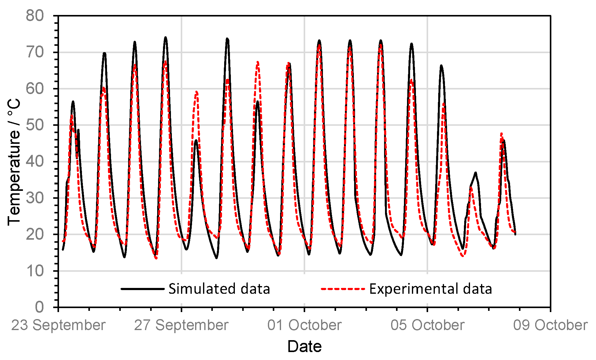
A comparison between measured and numerical data was performed for the indoor air temperatures of the PCM test cell (see
Figure 9).
The overlapping of results shows there was fairly good agreement between the numerical model and in situ measurements. The difference between the temperature curves was approximately 1 °C to 2 °C (
Figure 10) with a maximum difference of 10 °C at the maximum peak of temperature on 29 September.
As can be observed in
Figure 11, the correlation factor showed good agreement for both data: simulated and real. Thus, the model was considered validated.
4.2.2. Simulated Building’s Performance
Numerical simulations were carried out in order to analyze the PCM effect on the constructive solution, namely, on the floor. The numerical simulations allowed us to evaluate different strategies that we modeled for preventing overheating in the summer and consequently reducing the annual energy demand, thus preserving high thermal comfort inside the buildings.
Different scenarios were defined to evaluate the thermal behavior and optimize the use of the PCM to potentiate the charge and discharge process during a daily cycle.
The strategy consisted of increasing the fresh air entering each thermal zone when the exterior temperature was suitable for passive ventilation and the exterior wind velocity was at a maximum of 4 m s−1. Thus, in the cooling period, passive ventilation was activated based on the differential dry bulb temperature, that is, the outdoor air inflow rate increased when the outdoor air temperature was lower than the indoor air temperature.
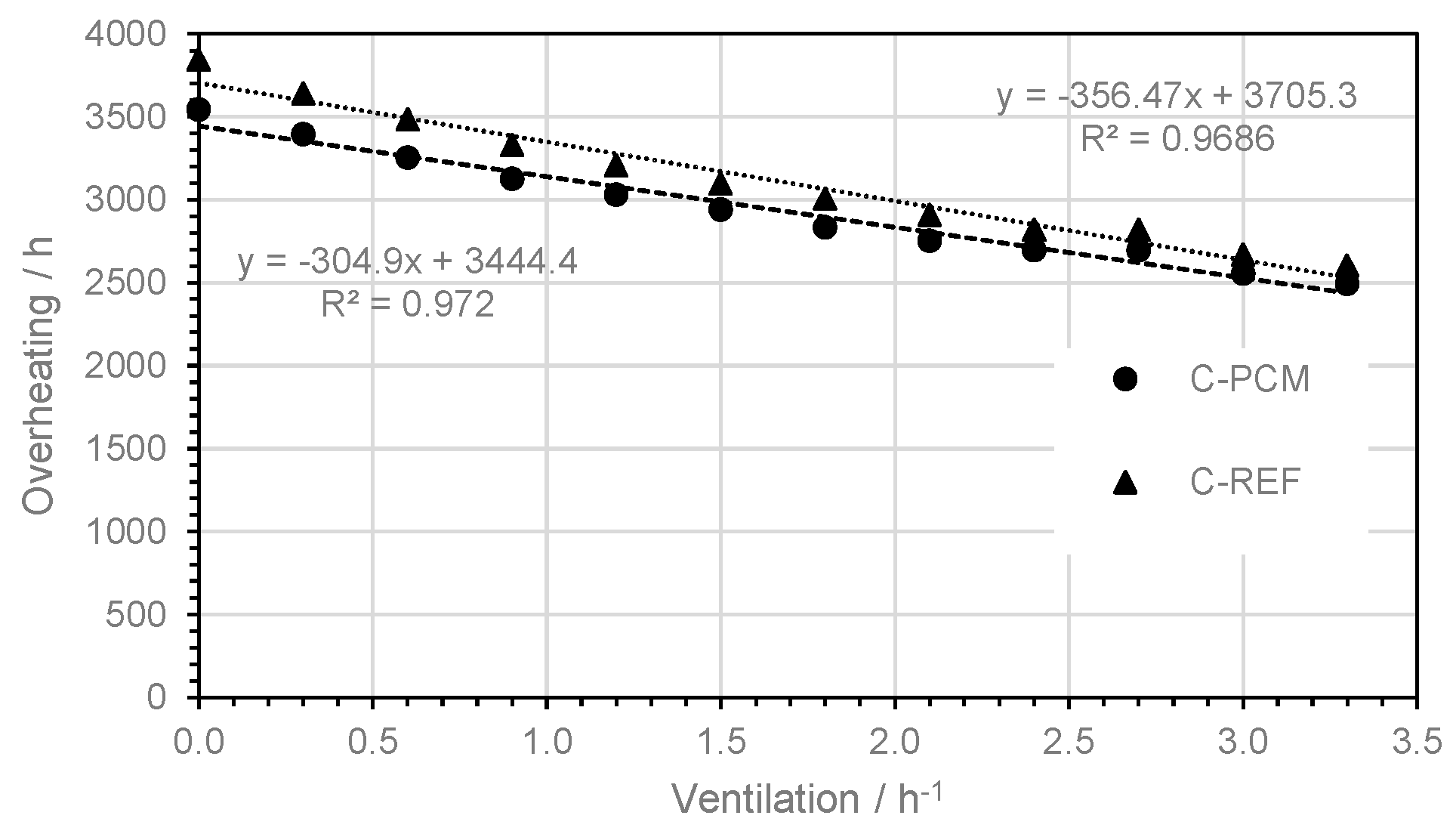
The PCM’s performance was characterized by evaluating the overheating rate during the summer season, which was considered to be between the months of May and October (
Figure 11), and also for the reference year (
Figure 12).
When analyzing the results from
Figure 11 and
Figure 12, the following conclusions can be drawn:
The increase in ventilation leads to a linear decrease in the overheating hours until reaching one renovation per hour, for both scenarios (C-PCM and C-REF);
For higher levels of ventilation (above 1 h−1), the overheating decreases more smoothly;
From the trendline analyses in both figures, it seems the latent heat capacity of the PCM can attenuate the impact of the ventilation rate on the indoor environment;
For high levels of ventilation, the charge and discharge process of the PCM occurs faster. Thus, the amount of PCM should be adequately defined, taking into account the ventilation level.
5. Conclusions
The work carried out in this study has proven the applicability and potential of PCM in constructive solutions, which should be highly incentivized for southern European climates.
Based on our assessment of the discomfort time for the heating season, it is possible to conclude that the PCM provides a potential thermal regulation effect (average thermal amplitude reduction of 18%), reducing the discomfort level through the attenuation of the temperature swing and peak temperatures reached in indoor spaces. However, the chosen melting point was essentially defined to improve the indoor comfort for the cooling season.
PCMs are a promising technology for improving energy efficiency and reducing greenhouse gas emissions. By incorporating PCMs in buildings, it is possible to reduce energy consumption for heating and cooling and provide a reliable form of thermal energy storage. With the continuous development of new and innovative systems incorporating PCMs, it is possible to unlock even more potential for sustainable energy storage.
However, to provide a more comprehensive evaluation of the impact of PCMs on indoor temperature fluctuations and thermal inertia, enhanced experimentation should be conducted. This must involve the combination of different passive strategies, so that those work together, aiming to reduce the excessive indoor air temperature reached in the test cell. This may include, e.g., shading devices to minimize the solar radiation inside the compartments. Furthermore, to optimize PCM behavior in terms of charging and discharging processes and thereby enhance energy-saving efficiency and thermal comfort in the test cell, additional exploration through numerical simulation regarding different PCM phase change ranges is deemed necessary.
Author Contributions
Conceptualization, A.S.; methodology, A.S.; validation, A.F., T.S., M.G. and A.S.; investigation, A.S.; resources, A.S.; data curation, A.F.; writing—original draft preparation, A.F.; writing—review and editing, A.F., T.S., M.G. and A.S.; supervision, A.S.; project administration, A.S.; funding acquisition, A.S. All authors have read and agreed to the published version of the manuscript.
Funding
This research was funded by the Foundation for Science and Technology (FCT)-Aveiro Research Centre for Risks and Sustainability in Construction (RISCO), Universidade de Aveiro, Portugal (FCT/UIDB/ECI/04450/2020 and UIDP/00481/2020—Fundação para a Ciência e a Tecnologia; DOI 10.54499/UIDB/00481/2020 (
https://doi.org/10.54499/UIDB/00481/2020) and DOI 10.54499/UIDP/00481/2020 (
https://doi.org/10.54499/UIDP/00481/2020)), and the Centro Portugal Regional Operational Programme (Centro2020; CENTRO-01-0145-FEDER-02208), under the PORTUGAL 2020 Partnership Agreement, through the European Regional Development Fund.
Data Availability Statement
The raw data supporting the conclusions of this article will be made available by the authors on request.
Conflicts of Interest
The authors declare no conflicts of interest.
References
- Lou, S.; Peng, Z.; Cai, J.; Zou, Y.; Huang, Y. Building Performance under Untypical Weather Conditions: A 40-Year Study of Hong Kong. Buildings 2023, 13, 2587. [Google Scholar] [CrossRef]
- Pervez, H.; Ali, Y.; Petrillo, A. A Quantitative Assessment of Greenhouse Gas (GHG) Emissions from Conventional and Modular Construction: A Case of Developing Country. J. Clean. Prod. 2021, 294, 126210. [Google Scholar] [CrossRef]
- Nations, U. Sustainable Development Goals. Available online: https://www.un.org/sustainabledevelopment/sustainable-development-goals/ (accessed on 13 December 2023).
- Zangheri, P.; Castellazzi, L.; D’agostino, D.; Economidou, M.; Ruggieri, G.; Tsemekidi-Tzeiranaki, S.; Maduta, C.; Bertoldi, P. Progress of the Member States in Implementing the Energy Performance of Building Directive; Publications Office of the European Union: Louxembourg, 2021; ISBN 9789276252009. [Google Scholar]
- Cakyova, K.; Figueiredo, A.; Oliveira, R.; Rebelo, F.; Vicente, R.; Fokaides, P. Simulation of Passive Ventilation Strategies towards Indoor CO2 Concentration Reduction for Passive Houses. J. Build. Eng. 2021, 43, 103108. [Google Scholar] [CrossRef]
- Hou, J.; Wei, D.; Meng, X.; Dewancker, B.J. Thermal Performance Analysis of Lightweight Building Walls in Different Directions Integrated with Phase Change Materials (PCM). Case Stud. Therm. Eng. 2022, 40, 102536. [Google Scholar] [CrossRef]
- Gonçalves, M.; Novais, R.M.; Senff, L.; Carvalheiras, J.; Labrincha, J.A. PCM-Containing Bi-Layered Alkali-Activated Materials: A Novel and Sustainable Route to Regulate the Temperature and Humidity Fluctuations inside Buildings. Build. Environ. 2021, 205, 108281. [Google Scholar] [CrossRef]
- Rebelo, F.; Figueiredo, A.; Vicente, R.; Ferreira, V.M. Study of a Thermally Enhanced Mortar Incorporating Phase Change Materials for Overheating Reduction in Buildings. J. Energy Storage 2022, 46, 103876. [Google Scholar] [CrossRef]
- National Renewable Energy Laboratory (NREL); U.S. Department of Energy (DOE). Passive Solar Design for the Home; National Renewable Energy Laboratory (NREL), U.S. Department of Energy (DOE): Washington, DC, USA, 2001.
- Christen, H.; van Zijl, G.; de Villiers, W. Improving Building Thermal Comfort through Passive Design—An Experimental Analysis of Phase Change Material 3D Printed Concrete. J. Clean. Prod. 2023, 392, 136247. [Google Scholar] [CrossRef]
- Rao, V.V.; Parameshwaran, R.; Ram, V.V. PCM-Mortar Based Construction Materials for Energy Efficient Buildings: A Review on Research Trends. Energy Build. 2018, 158, 95–122. [Google Scholar] [CrossRef]
- Frahat, N.B.; Amin, M.; Heniegal, A.M.; Ibrahim, O.M.O. Optimizing Microencapsulated PCM Ratios of Sustainable Cement Mortar for Energy Savings in Buildings. Constr. Build. Mater. 2023, 391, 131844. [Google Scholar] [CrossRef]
- Bat-Erdene, P.E.; Pareek, S.; Koenders, E.; Mankel, C.; Löher, M.; Xiao, P. Evaluation of the Thermal Performance of Fly Ash Foam Concrete Containing Phase Change Materials (PCMs). Buildings 2023, 13, 2481. [Google Scholar] [CrossRef]
- Gupta, M.K.; Rathore, P.K.S.; Kumar, R.; Gupta, N.K. Experimental Analysis of Clay Bricks Incorporated with Phase Change Material for Enhanced Thermal Energy Storage in Buildings. J. Energy Storage 2023, 64, 107248. [Google Scholar] [CrossRef]
- Mahdaoui, M.; Hamdaoui, S.; Msaad, A.A.; Kousksou, T.; El Rhafiki, T.; Jamil, A.; Ahachad, M. Building Bricks with Phase Change Material (PCM): Thermal Performances. Constr. Build. Mater. 2021, 269, 121315. [Google Scholar] [CrossRef]
- Amaral, C.; Silva, T.; Mohseni, F.; Amaral, J.S.; Amaral, V.S.; Marques, P.A.A.P.; Barros-Timmons, A.; Vicente, R. Experimental and Numerical Analysis of the Thermal Performance of Polyurethane Foams Panels Incorporating Phase Change Material. Energy 2021, 216, 119213. [Google Scholar] [CrossRef]
- Marín, P.E.; Ushak, S.; de Gracia, A.; Cabeza, L.F. Characterisation of the COMFORTBOARD Gypsum Board for Thermal Energy Storage in Buildings. J. Energy Storage 2024, 77, 109850. [Google Scholar] [CrossRef]
- Bravo, J.P.; Venegas, T.; Correa, E.; Álamos, A.; Sepúlveda, F.; Vasco, D.A.; Barreneche, C. Experimental and Computational Study of the Implementation of MPCM-Modified Gypsum Boards in a Test Enclosure. Buildings 2020, 10, 15. [Google Scholar] [CrossRef]
- Askari, M.; Jahangir, M.H. Evaluation of Thermal Performance and Energy Efficiency of a Trombe Wall Improved with Dual Phase Change Materials. Energy 2023, 284, 128587. [Google Scholar] [CrossRef]
- Li, C.; Yang, X.; Peng, K. Performance Study of a Phase Change Material Trombe Wall System in Summer in Hot and Humid Area of China. Energy Rep. 2021, 8, 230–236. [Google Scholar] [CrossRef]
- Mobaraki, B.; Pascual, F.J.C.; Garcia, A.M.; Mascaraque, M.Á.M.; Vázquez, B.F.; Alonso, C. Studying the Impacts of Test Condition and Nonoptimal Positioning of the Sensors on the Accuracy of the In-Situ U-Value Measurement. Heliyon 2023, 9, e17282. [Google Scholar] [CrossRef]
- Mobaraki, B.; Komarizadehasl, S.; Castilla Pascual, F.J.; Lozano-Galant, J.A. Application of Low-Cost Sensors for Accurate Ambient Temperature Monitoring. Buildings 2022, 12, 1411. [Google Scholar] [CrossRef]
- Ascione, F.; Bianco, N.; De Masi, R.F.; de’ Rossi, F.; Vanoli, G.P. Energy Refurbishment of Existing Buildings through the Use of Phase Change Materials: Energy Savings and Indoor Comfort in the Cooling Season. Appl. Energy 2014, 113, 990–1007. [Google Scholar] [CrossRef]
- Berardi, U.; Manca, M. The Energy Saving and Indoor Comfort Improvements with Latent Thermal Energy Storage in Building Retrofits in Canada. Energy Procedia 2017, 111, 462–471. [Google Scholar] [CrossRef]
- Jiang, W.; Jin, Y.; Liu, G.; Li, Q.; Li, D. Passive Nearly Zero Energy Retrofits of Rammed Earth Rural Residential Buildings Based on Energy Efficiency and Cost-Effectiveness Analysis. Renew. Sustain. Energy Rev. 2023, 180, 113300. [Google Scholar] [CrossRef]
- Berardi, U.; Soudian, S. Experimental Investigation of Latent Heat Thermal Energy Storage Using PCMs with Different Melting Temperatures for Building Retrofit. Energy Build. 2019, 185, 180–195. [Google Scholar] [CrossRef]
- Choi, J.Y.; Nam, J.; Yuk, H.; Yun, B.Y.; Lee, S.; Lee, J.K.; Kim, S. Proposal of Retrofit of Historic Buildings as Cafes in Korea: Recycling Biomaterials to Improve Building Energy and Acoustic Performance. Energy Build. 2023, 287, 112988. [Google Scholar] [CrossRef]
- Imafidon, O.J.; Ting, D.S.K. Retrofitting Buildings with Phase Change Materials (PCM)—The Effects of PCM Location and Climatic Condition. Build. Environ. 2023, 236, 110224. [Google Scholar] [CrossRef]
- Park, J.H.; Jeon, J.; Lee, J.; Wi, S.; Yun, B.Y.; Kim, S. Comparative Analysis of the PCM Application According to the Building Type as Retrofit System. Build. Environ. 2019, 151, 291–302. [Google Scholar] [CrossRef]
- Park, J.H.; Berardi, U.; Chang, S.J.; Wi, S.; Kang, Y.; Kim, S. Energy Retrofit of PCM-Applied Apartment Buildings Considering Building Orientation and Height. Energy 2021, 222, 119877. [Google Scholar] [CrossRef]
- Park, J.H.; Yun, B.Y.; Chang, S.J.; Wi, S.; Jeon, J.; Kim, S. Impact of a Passive Retrofit Shading System on Educational Building to Improve Thermal Comfort and Energy Consumption. Energy Build. 2020, 216, 109930. [Google Scholar] [CrossRef]
- Evola, G.; Marletta, L. The Effectiveness of PCM Wallboards for the Energy Refurbishment of Lightweight Buildings. Energy Procedia 2014, 62, 13–21. [Google Scholar] [CrossRef]
- Far, C.; Far, H. Improving Energy Efficiency of Existing Residential Buildings Using Effective Thermal Retrofit of Building Envelope. Indoor Built Environ. 2019, 28, 744–760. [Google Scholar] [CrossRef]
- Baniassadi, A.; Sailor, D.J.; Bryan, H.J. Effectiveness of Phase Change Materials for Improving the Resiliency of Residential Buildings to Extreme Thermal Conditions. Sol. Energy 2019, 188, 190–199. [Google Scholar] [CrossRef]
- Building Technologies Office (BTO); U.S. Department of Energy (DOE). EnergyPlusTM; version 9.0; Building Technologies Office (BTO), U.S. Department of Energy (DOE): Washington, DC, USA, 2023.
- ISO 7726; Ergonomics of the Thermal Environment, Instruments for Measuring Physical Quantities. International Organization for Standardization (ISO): Geneva, Switzerland, 1998.
- Lavine, A.G.; Rucker, J.L.; Wilkes, K.E. Flanking Loss Calibration for a Calibrated Hot Box. In Thermal Insulation, Materials, and Systems for Energy Conservation in the ‘80s; ASTM International: West Conshohocken, PA, USA, 1983; pp. 234–247. [Google Scholar] [CrossRef]
- ISO 6781; Thermal Insulation—Qualitative Detection of Thermal Irregularities in Building Envelopes—Infrared Method. International Organization for Standardization (ISO): Geneva, Switzerland, 1983.
- ISO/FDIS 9869-2; Thermal Insulation—Building Elements—In-Situ Measurement of Thermal Resistance and Thermal Transmittance—Part 2: Infrared Method for Frame Structure Dwelling. International Organization for Standardization (ISO): Geneva, Switzerland, 2018.
- Empresa, P. Da Pesquisa de Nomes Existentes. Available online: https://eportugal.gov.pt/RegistoOnline/Services/PesquisaSICONF/PesquisaSICONF.aspx (accessed on 12 December 2022).
- Cimpor Portugal – CEM I 42.5 R. Available online: https://www.cimpor.com/-/cem-i-425-r (accessed on 13 December 2023).
- Microtek Laboratories Inc. MICRONAL® DS 5040 X; Microtek Laboratories Inc.: Dayton, OH, USA, 2018. [Google Scholar]
- Miller, R.; Perrine, E.; Linehan, P. A Calibrated/Guarded Hot-Box Test Facility. In Thermal Transmission Measurements of Insulation; ASTM International: West Conshohocken, PA, USA, 1978; pp. 329–341. [Google Scholar] [CrossRef]
- Salgueiro, T.; Samagaio, A.; Gonçalves, M.; Figueiredo, A.; Labrincha, J.; Silva, L. Incorporation of Phase Change Materials in an Expanded Clay Containing Mortar for Indoor Thermal Regulation of Buildings. J. Energy Storage 2021, 36, 102385. [Google Scholar] [CrossRef]
- Da Silva Monteiro, C.S. Estudo de Um Edifício Solar Passivo de Ganho Direto Usando Um PCM. Ph.D. Thesis, University of Aveiro, Aveiro, Portugal, 2014. [Google Scholar]
- Nunes, H.F.S. Comportamento Térmico de Uma Argamassa Com PCM Numa Célula-de-Teste. Ph.D. Thesis, University of Aveiro, Aveiro, Portugal, 2013. [Google Scholar]
- Johansson, P.; Adl-Zarrabi, B.; Hagentoft, C.E. Using Transient Plane Source Sensor for Determination of Thermal Properties of Vacuum Insulation Panels. Front. Archit. Res. 2012, 1, 334–340. [Google Scholar] [CrossRef]
- Fatahi, H.; Claverie, J.; Poncet, S. Thermal Characterization of Phase Change Materials by Differential Scanning Calorimetry: A Review. Appl. Sci. 2022, 12, 12019. [Google Scholar] [CrossRef]
- ISO 9060; Solar Energy, Specification and Classification of Instruments for Measuring Hemispherical Solar and Direct Solar Radiation. International Organization for Standardization (ISO): Geneva, Switzerland, 2018.
| Disclaimer/Publisher’s Note: The statements, opinions and data contained in all publications are solely those of the individual author(s) and contributor(s) and not of MDPI and/or the editor(s). MDPI and/or the editor(s) disclaim responsibility for any injury to people or property resulting from any ideas, methods, instructions or products referred to in the content. |
© 2024 by the authors. Licensee MDPI, Basel, Switzerland. This article is an open access article distributed under the terms and conditions of the Creative Commons Attribution (CC BY) license (https://creativecommons.org/licenses/by/4.0/).


