Abstract
Since the stability of slopes in infrastructures such as road and railroad embankments, excavations, and, in general, earthwork is important, analyzing the stability of these slopes has been one of the main focuses of geotechnical engineers. Although analyzing both reinforced and unreinforced slopes is needed, reinforced slopes require special attention as the reinforcement elements significantly affect the calculations. Hence, the current study’s aim is to find out the differences between obtained safety factors using the Limit Equilibrium Method (LEM) and Shear Strength Reduction Method (SSRM). For this purpose, first, the origin differences in terms of Safety Factor (SF) are theoretically determined according to basic formulas for the aforementioned techniques. Then, to verify the formula, several numerical modelings are carried out using in situ measured geotechnical data to better understand the differences in terms of safety factors. The results indicate that for the reinforced slope with an SF value of higher than 1, the SSRM provides a higher SF in comparison with the other techniques, and the origin of this difference is the definitions of the SF in the different methods.
1. Introduction
The term “slope stability analysis” refers to evaluating the stability of earthworks, including embankments, excavated slopes, and earth dams, as well as natural soil and rock slopes using dynamic or static analytical or empirical techniques. Slope stability analysis is one of the most common problems geotechnical engineers face. The stability of slopes is estimated using different methods, and each has several advantages and limitations. Knowing more about these methods and their differences helps engineers choose the method that suits the project conditions and has the best prediction. Analyses are mostly aimed at understanding the causes of an occurred slope failure or effective factors associated with initiating a slope movement. They are also used to prevent the trigger of movements that result in landslides, slowing down or discontinuing them using mitigation techniques. Although several approaches have been developed for analyzing the stability of both reinforced and unreinforced slopes used in civil infrastructures, the Limit Equilibrium Method (LEM) and Shear Strength Reduction Method (SSRM) are frequently used by engineers and researchers. Therefore, in this section, each of the mentioned methods will be first described in detail and then followed by a review of the relevant studies.
To begin with, the Limit Equilibrium Method is the most popular methodology for analyzing the stability of both artificial and natural slopes in two and three dimensions [1]. Possible failure mechanisms and associated safety factors for a particular geotechnical situation are usually detected by this method [1]. The Limit Equilibrium Method lacks unique factors of safety due to its dependence on assumptions like defining inter-slice forces distribution and failure surface shape. This sensitivity emphasizes the potential variability in slope stability analysis outcomes [2]. The Limit Equilibrium Method (LEM) does not account for the stress–strain behavior of soil or consider certain soil parameters like dilatancy [3]. Nevertheless, its ability to rapidly estimate slope safety factors has made it widely favored among geotechnical engineers and researchers [4,5]. The industry has accepted the Limit Equilibrium Method as the standard thanks to its effectiveness in conducting simpler and faster analyses [6]. In recent decades, the LEM has been frequently used by geotechnics engineers and researchers to analyze the stability of both rock and soil [2,4,7,8,9,10,11]. For instance, Lee et al. [12] developed a new estimate of the Mohr envelope for the generalized Hook–Brown (GHB) criterion, which is valid in a broad range of Geological Strength Index (GSI) values. The outcomes show that the safety factor for the stability of the slope was very sensitive to the crack geometry (i.e., its depth and location), along with the selection of the GSI value. A new 3D slope stability analysis method based on stress calculation by the finite-element method was proposed by Su and Shao [13]. This method approved the uniform assumption of the sliding direction of the rigid LEM so that it can be easily used to calculate the 3D sliding direction. Recently, a new study has been dedicated to evaluating and modeling the slope stability in view of different scenarios in 2D and 3D [14]. One of the main results of this study is that Spencer’s and Morgenstern and Price’s methods can confidently be used for 2D solutions in almost all cases with various types of water conditions, external effects, slip surfaces, and geological characteristics. Villalobos and Villalobos [15] evaluated the effect of nail spacing with the assumption of a bilinear failure surface with the Morgenstern–Price method and two rigid blocks, where the failure shape is neither linear nor circular. According to the obtained results, they finally suggested using FEM instead of LEM, where analyzing the stability of nail-reinforced soil is required.
The Shear Strength Reduction Method (SSRM) for slope stability analysis encompasses the systematic use of finite-element (FE) analysis to determine a safety factor magnitude associated with the threshold of slope failure [16]. This technique was first proposed by Zienkiewicz et al. in 1975 [17], and since then, it has been regularly used by researchers for many purposes. Issues related to complex geometries or analysis of seepage, consolidation, and coupled hydrological and mechanical behaviors may find better solutions through the use of FE analysis [18]. One of the prime studies associated with FE analysis of slope stability was investigated by Matsui and San in 1992 [19]. One of the notable achievements of this study was showing that SSRM has a satisfactory agreement with Fellenius’ method. Moreover, it was revealed that in the case of using total shear strain for embankment slope analyses, the critical shear strength reduction ratio agreed with the factor of safety obtained by Bishop’s method. Another basic and reputed study in the scope of SSRM was carried out by Dawson et al. in 1999 [20]. They examined a wide range of pore pressure coefficients, soil friction angles, and slope angles to evaluate the safety of slopes according to a log-spiral failure mechanism. The results indicated that FS obtained using SSRM was mostly a touch higher than those calculated by limit analysis. Hammah et al. [21] modeled Generalized Hoek–Brown materials directly using SSRM to analyze the slope stability of rocks. In another study carried out by Fu and Liao [22], the non-linear Hoek–Brown shear strength reduction technique was implemented in calculations of slope stability of rock mass subjected to different stress conditions [21]. A case study of a failed slope, the Surabhi Resort landslide, was evaluated using FE analysis adopting SSRM [23]. The result of this approach showed a good confirmation of the previous analysis carried out on this landslide. The effects of dilatancy angle on slope stability were three-dimensionally assessed using the FE method considering SSRM by Lin et al. [3]. The findings showed that the angle of dilation affects slope stability considerably. Hence, they suggested this parameter should be considered when evaluating slope stability is required. Luo et al. [24] investigated probabilistic analyses of geosynthetic-reinforced soil slopes using SSRM in a finite-element environment. The results indicated that obtained factor of safety for reinforced slopes analyzed using LEM may not be the same as those estimated by modified FEM. In another study, carried out by Wei et al. [25], the effect of the presence of water flow on the stability of the slope was investigated using SSRM. It was shown that there is a slight difference in obtained safety factors between considering pore pressure water within clay soil slopes and the absence of it. This effect is noticeable, on the other hand, for sandy soil slopes. A reinforced slope with one row of piles was analyzed using the strength reduction technique by Wei and Cheng (2009) [16]. The main output of this study revealed the fact that the location of maximum shear force within a pile is not necessarily where the critical slip surface of a piled-reinforced slope occurs.
Many researchers, on the other hand, compared the safety factor obtained from LEM with SSRM [2,3,4,7,9,10,11,15,26,27,28]. In the following, some of these studies, preferably the recent and straightforward ones, are opened up and explained. A pioneering study carried out by Ugai and Leshchinsky in 1995 [27] was dedicated to numerically comparing the results of three-dimensional LEM and SSRM analyses. However, the comparisons were restricted to vertical cuts and encompassed a pseudo-static seismic force component. The outcomes revealed that factors of safety and their linked slip failure resulting from both methods were in a fitting agreement, though the two analyses were fundamentally different. We et al. [26] (2009) performed 3D slope stability analyses using both LEM and SSRM for some cases. It was found that the safety factors resulting from the two techniques were in good agreement in terms of safety factors and failure modes. In another study, recently done by Villalobos et al. (2021) [15], the effect of space between nails on the global stability of a nail-reinforced wall was investigated by adopting both LEM and SSRM techniques. The result of this study indicated that the safety factors obtained by SSRM represented a significant improvement in comparison with those attained using LEM; therefore, the authors suggested SSRM for designing nail spacing. Tschuchnigg et al. (2015) [28] carried out the same study in which SSRM and finite-element limit analysis results were compared in terms of safety factors and the associated failure surface. It was shown that for sharp slopes with a low safety factor and angle of friction higher than 40 degrees, the flow rule may play a key role in the outcomes.
Having reviewed previous studies associated with the Safety Factor (SF) and the relevant failure surface calculated by the Shear Strength Reduction Method (SSRM) and Limit Equilibrium Method (LEM), it was found that there is still an unbridged gap highlighting the real difference between SF obtained from the two aforementioned techniques. Therefore, the current study is dedicated to revealing this difference using both theoretical and numerical analysis. In the theoretical step, the basic equations for calculating the safety factor are expressed based on the Limit Equilibrium Method. These formulas are expanded according to the definitions in the Shear Strength Reduction Method for both reinforced and unreinforced states until the definitions are comparable with the safety factor in the Shear Strength Reduction Method. Then, using FE and LE modeling, the results from the theoretical step are validated for both reinforced and unreinforced earth slopes. Geotechnical data was collected from a real site located in Tehran, Iran, for numerical analysis.
2. Slope Stability Analysis Approaches
In this section, LEM, ELEM, and SSRM are theoretically explained for reinforced slopes to clarify the origin of safety factor calculation for each technique. Since the main focus of the current study is on the SSRM technique, the methodology of this technique is also opened in detail to determine how this method is considered reinforcement for calculating safety factors.
2.1. LEM Methodology
In accordance with Sweden’s national standards entitled “Construction Side Slope Engineering Technology Standard” [29], the arc technique is suitable for stability analysis of soil slopes (see Figure 1). The reinforcement elements can be substituted with forced as follows:
where is the horizontal spacing of the first row of reinforced element rods, is the maximum resistance of the first k rows associated with the reinforced slice, is the included angle between the first k rows of reinforced element rod and tangent of the arch, and is the friction angle of slice i. By considering the contribution of anchored reinforcement, the calculation formula of safety factor can be defined for the reinforce-slope as follows:
where , , , and are soil weight and surface loads of slice i, intersection angle between the tangent of the first i slice arch failure surface and horizontal plane, cohesion force of slice i, and length of slip surface, respectively. The reinforced section has a pull-out resistance, where , and are the shear resistance of grout, anchor section length, and the anchor section diameter, respectively.
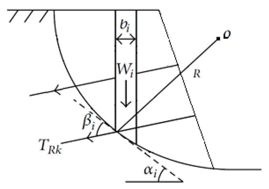
Figure 1.
Stability analysis for reinforced soil slope using slice method [2].
In the plane strain assumption, the failure surface is presumed to be a circular arc in many existing LEMs. On the other hand, numerical analysis has shown that the failure surface shape might be a combination of a circular arc and a straight line or a logarithmic spiral and a straight line. However, it has been revealed that optimization methods are the most capable means of locating noncircular slip surfaces [30,31].
2.2. Enhanced LEM
Referring to the approach of reinforcing slope stability analysis with the slice technique and merging it with the finite-element stress analysis, the safety factor of the reinforced slope is defined as [2]:
where and are the allowable shear strength and the actual shearing stress on the slip surface, respectively. It should be noted that in the ELEM, an optimization technique is usually used to locate the surface of critical slip [10].
2.3. SSRM Methodology
In slope stability analysis using SSRM, the FS is defined as the factor by which the original shear strength parameters must be divided to bring the slope to the point of failure [32].
Cohesion, and friction angle ∅ can be reduced by strength reduction factor S. Then we use the ideal elastic–plastic stress–strain model and the Mohr–Coulomb yield criterion with an iterative calculation based on the no associated flow rules and take the non-convergence of finite-element calculation as instability criterion. The FS is equal to the value of the S that causes the slope to fail.
where and are reduced cohesion and friction angle slopes at the occurrence of failure.
2.3.1. Unreinforced Slopes
To compare the SF obtained from SSRM, it is assumed that the SF is calculated using Formula (3). To simplify, we first apply the contents to unreinforced slopes.
In unreinforced slopes:
As mentioned, the software calculates SF in such a way that reduces the soil shear parameters until failure occurs. Assuming the failure occurrence:
By placing (6) in (5):
On the other hand, cohesion C, and friction angle ∅ are reduced by strength reduction factor S.
In Equation (7), if C and tan∅ are substituted with and , respectively:
From Equation (9), it can be demonstrated that the FS is similar to the conventional SSRM. Griffiths and Lane noted that this definition of the FS in SSRM is the same as the one used in the LEM [32].
2.3.2. Reinforced Slopes
Similarly, for the reinforced slopes, the SF is defined as:
If the parameters at the time of failure substitute, then:
where and are reduced cohesion and friction angle for reinforced slopes at failure occurrence, respectively. For forces, the equation below is true:
From the combination of Equations (10) and (12):
Based on Equation (6):
On the other hand, cohesion C, and friction angle ∅ are reduced by strength reduction factor S2.
From a combination of equations of (14), (15), and (8):
It can be seen that the assumptions of the Shear Strength Reduction Method are different from the previous two methods. Using recursive proof, it can be proved that the conventional Shear Strength Reduction Method uses the following formula to obtain the SF associated with reinforced slopes. This formula is different from the previous two methods.
Because:
In two modes, SSRM calculates the factor of safety based on two previous techniques, LEM and ELEM, for the obtaining of which the equation below should be solved:
The first mode is associated with unreinforced slopes, while the second mode is when the safety factor is equal to one.
For comparing FS at other different spots, it is possible to place C, and in and formulas and then calculate and compare the results.
Figure 2 is a summary of the abovementioned results, showing the obtained safety factor versus for two techniques of SSRM and LEM qualitatively. From the figure, it can be obviously seen that the safety factor at point is 1, irrespective of the technique used. By decreasing , the gap between SF calculated by SSRM and LEM is gradually raised. It can be the result that in the reinforced slopes, the SF calculated by SSRM gives a higher magnitude in comparison with LEM for (reduced soil cohesion at failure) less than C (actual cohesion of soil), while both techniques give the same value for SF equal to 1 and less.
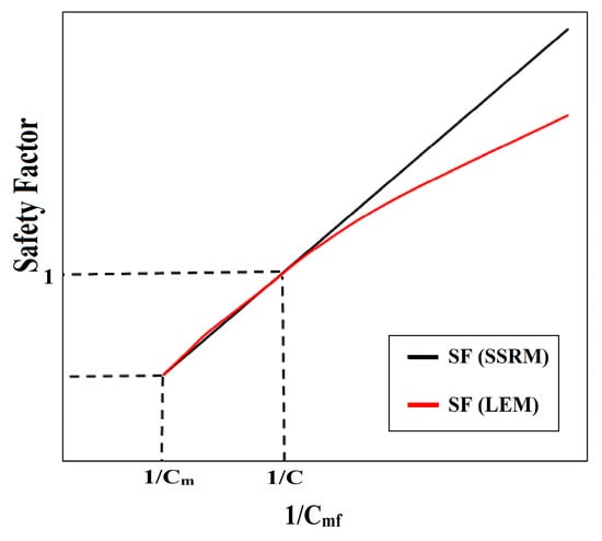
Figure 2.
versus safety factor calculated by SSRM and LEM.
3. Finite-Element Stability Analysis
In this section, a numerical simulation is developed based on actual data provided from a real project located in Tehran, Iran (see Figure 3 and Figure 4). To simulate the reinforced soil and unreinforced slope, two well-known pieces of commercial geotechnical software—PLAXIS 2D V8.6 [33] and GeoStudio—were used. To compare the obtained safety factor of the slopes, the LEM technique is adopted in GeoStudio software v.2012, while SSRM is used in PLAXIS 2D. It should be clarified that in the GeoStudio, the three methods of Morgenstern–Price, Spencer, and Bishop are adopted for obtaining the safety factor, whereas in the PLAXIS, the SSRM method with plain strain is used. To analyze the model more precisely, 15-node tri-angular elements were assumed for the materials in Plaxis 2D. For simulation interaction between the surrounding soil and the reinforcement elements, an interface value of 0.95, denoted R inter, was applied to the model.
The “drained” condition was adopted for the models as the site tests confirmed the absence of pore water pressure on the site. Moreover, based on shear strength tests performed on the site soil and the essence of the topic, the elastoplastic assumptions of the Mohr–Coulomb and Hardening soil models were applied for the soil material in GeoStudio and Plaxis, respectively.
3.1. Site and Material Specifications
To compare the SF driven from different aforementioned techniques, a real geotechnical site located in Tehran was chosen to be numerically modeled. This site, which is associated with multiple buildings, has a deep excavation where the foundation is placed at the level of −20.5 m from the natural ground surface. In the current project, a series of lab and in situ tests were performed to determine the geotechnical properties of the soil profile. As an example of these tests, Figure 3 depicts a trench and an intact cubic soil sample related to the in situ direct shear strength test.
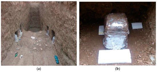

Figure 3.
In situ direct shear strength test: (a) an access trench, (b) an intact cubic soil sample.
In the current study, the type AIII bar was used as nails and anchors with the given specification in Table 1. Technical characterization of nail and anchor are summarized in Table 2. It should be noted that 5 strands were used in each anchor. It should also be clarified that the magnitude of bond skin friction for both nails and anchors was obtained from the pull-out test carried out in accordance with FHW [33,34].
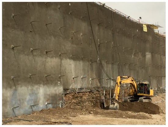

Figure 4.
A view of the site project.

Table 1.
Soil profile characteristics.

Table 2.
Technical characterization of nail and anchor (one strand).
3.2. Geometry and Boundary Conditions
The geometry and boundary conditions of the models are almost the same as the site project (see Figure 5) except for the slope angle of the front face in the unreinforced model, which is 45 degrees (see Figure 6 and Figure 7). The aim of considering this slope was obtaining SF higher than 1 to compare results understandably. With respect to boundary conditions, to avoid the influence of boundaries, the length and height of the models are appropriately extended, as can be seen in Figure 5. The boundaries are completely fixed except for displacement in the y-direction of the rear and front faces of the model (see Figure 5). It should also be noted that a uniform distributed load of 10 kN/m2 is applied over the top of the slope to consider traffic loads adjacent to the project.
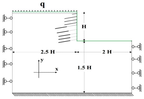
Figure 5.
Schematic diagram of the reinforced model and constraint condition.
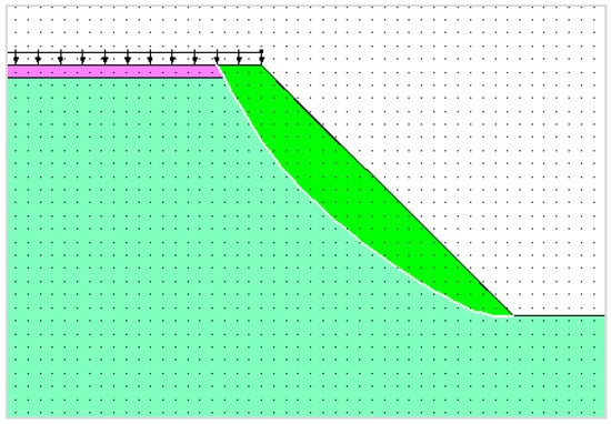
Figure 6.
Failure surface in GeoStudio software v.2012 adopting Morgenstern–Price technique (SF = 1.33).
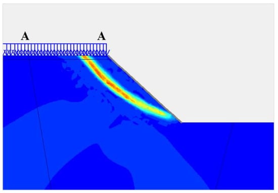
Figure 7.
Failure surface in PLAXIS V8.6.
4. Results and Discussion
4.1. Unreinforced Inclined 45° Slope
Two methods, namely the slice method and SSRM, are used in the stability analysis of the slope without any reinforced segments. In the Limit Equilibrium Method, GeoStudio software v.2012, one of the well-known pieces of software in the study of slope stability, is used. This software can calculate the SF using different equilibrium methods. In this research, three methods of Spencer, modified Bishop, and Morgenstern–Price have been used. On the other hand, the SSRM method is adopted in Plaxis softwareV8.6 to obtain the safety factor. The analysis results of the two methods are summarized in Table 3.

Table 3.
Safety factors in unreinforced soil slope.
The results indicate that the safety factor obtained from the SSRM method is less than LEM, with a slight difference of 2%. This outcome is in agreement with previous studies, which showed an insignificant difference between SF resulting from SSRM, ELSM, and LEM [2,4,10,35,36].
4.2. Reinforced Slope
To evaluate the above results, a vertically reinforced soil slope with a height of 19 m has been modeled and analyzed according to real-site data by two methods: SSRM and LEM. All soil and load characteristics are the same as the unreinforced model. Figure 8 shows the horizontal displacement against the height of the reinforced wall. The results rationally indicate decreasing displacement with increasing depth as the maximum of 30 mm is obtained almost at the surface of the model. Previously, to monitor the lateral displacement of the reinforced wall, horizontal displacement of the wall was recorded at depths of 1 m and 9.55 m using a Total Station Camera by 24 and 13 mm, respectively. From in situ measuring data, the values obtained using numerical modeling show good confirmation and denote that the model is working correctly. Figure 9 and Figure 10 show the section view of failure surfaces in GeoStudio 2012 and Plaxis V8.6.
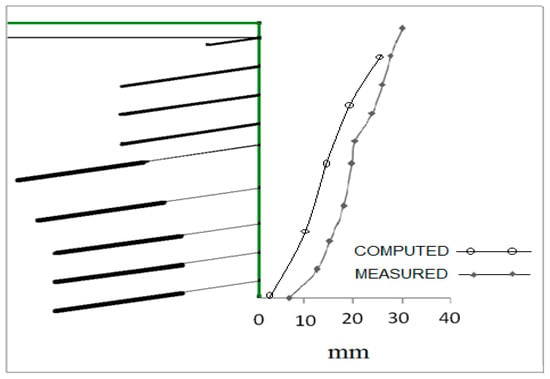
Figure 8.
Horizontal displacement of the front face of the nail-reinforced wall with a height of 19 m.
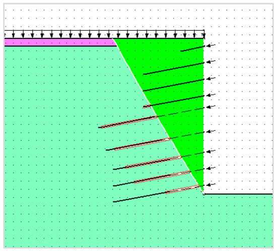
Figure 9.
A section view of failure surface in GeoStudio 2012 using Morgenstern–Price technique (FS = 1.31).
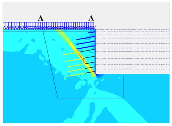
Figure 10.
Failure surface in the nail-reinforced model in the Plaxis V8.6.
From the data provided in Table 4, the magnitude of the safety factor in the SSRM method is 4.3% higher than the average Limit Equilibrium Method, while in the unreinforced state, it was 2.2% lower. After reinforcing the slope by anchor and nail, the safety factor from limit equilibrium methods irrationally decreases approximately by 1.7% compared to the unreinforced slope, whereas the safety factor from SSRM increases approximately by 6.6%. This change in the values of the safety factor can be due to differences in the hypotheses to define the safety factor, as mentioned, in the reinforced soil slopes; the conventional SSRM method calculates the safety factor from a different formula than the previous two methods which give us a more accurate amount of safety factor. Previous studies have also declared that safety factor change for reinforced slopes in the SSRM method is greater than in the LEM and ELSM [2,24].

Table 4.
Safety factors in reinforced soil slope.
5. Concluding Remarks
The current study is dedicated to finding the differences between the safety factors of reinforced and unreinforced slopes calculated using the Limit Equilibrium Method (LEM) and Shear Strength Reduction Method (SSRM). For this purpose, first, the differences are investigated theoretically according to the basic formulation of each methodology. The main results of this study can be categorized as follows:
- For determining safety factors in reinforced slopes, the SSR method uses a completely different formula compared to LEM. This marks a noticeable difference in the obtained safety factor.
- For unreinforced slopes and in the case of a safety factor equal to 1, the safety factor is calculated based on an identical definition for the three techniques: SSRM, LEM, and ELEM.
- For the reinforced slope with an SF value of higher than 1, the SSRM provides a higher SF compared to the other techniques.
Then, using FE and LE modeling, the results are validated for both reinforced and unreinforced earth slopes. The data for FE and LE modeling is collected from a deep excavation project located in Tehran. In LE modeling, the three techniques—Morgenstern–Price, Spencer, and Bishop—were adopted, while for FE modeling, the SSRM technique is used. Based on the numerical outcomes in the reinforced state, the obtained SF using SSRM is 4.3% higher than the average LEM values, while in the unreinforced state, it is lower by 2.2%. This result is consistent with the results (number 3) presented above.
Author Contributions
Supervision, S.M.R.I. and M.M.R.; Formal analysis, S.H. and S.M.R.I.; Writing—review and editing, Conceptualization, F.A.; Investigation, Visualization, J.C.; Validation, Original draft, S.H.; Methodology, S.M.R.I.; Editing and Review, M.M.R. All authors have read and agreed to the published version of the manuscript.
Funding
This research received no external funding.
Data Availability Statement
The datasets are present in the work.
Conflicts of Interest
The authors declare that they have no known competing financial interests or personal relationships that could have appeared to influence the work reported in this paper.
References
- Huang, Y.H. Slope Stability Analysis by the Limit Equilibrium Method: Fundamentals and Methods; American Society of Civil Engineers: Reston, VA, USA, 2014. [Google Scholar]
- Zhang, R.; Zhao, J.; Wang, G. Stability analysis of anchored soil slope based on finite element limit equilibrium method. Math. Probl. Eng. 2016, 2016, 7857490. [Google Scholar] [CrossRef]
- Lin, H.D.; Wang, W.C.; Li, A.J. Investigation of dilatancy angle effects on slope stability using the 3D finite element method strength reduction technique. Comput. Geotech. 2020, 118, 103295. [Google Scholar] [CrossRef]
- Cheng, Y.M.; Lansivaara, T.; Wei, W.B. Two-dimensional slope stability analysis by limit equilibrium and strength reduction methods. Comput. Geotech. 2007, 34, 137–150. [Google Scholar] [CrossRef]
- Azarafza, M.; Akgün, H.; Ghazifard, A.; Asghari-Kaljahi, E.; Rahnamarad, J.; Derakhshani, R. Discontinuous rock slope stability analysis by limit equilibrium approaches–a review. Int. J. Digit. Earth 2021, 14, 1918–1941. [Google Scholar] [CrossRef]
- Memon, Y. A comparison between limit equilibrium and finite element methods for slope stability analysis. Mo. Univ. Sci. Technol. Roll. 2018. [Google Scholar] [CrossRef]
- Rawat, S.; Gupta, A.K. Analysis of a nailed soil slope using limit equilibrium and finite element methods. Int. J. Geosynth. Ground Eng. 2016, 2, 34. [Google Scholar] [CrossRef][Green Version]
- Liu, S.; Su, Z.; Li, M.; Shao, L. Slope stability analysis using elastic finite element stress fields. Eng. Geol. 2020, 273, 105673. [Google Scholar] [CrossRef]
- Tschuchnigg, F.; Schweiger, H.F.; Sloan, S.W. Slope stability analysis by means of finite element limit analysis and finite element strength reduction techniques. Comput. Geotech. 2015, 70, 178–189. [Google Scholar] [CrossRef]
- Liu, S.Y.; Shao, L.T.; Li, H.J. Slope stability analysis using the limit equilibrium method and two finite element methods. Comput. Geotech. 2015, 63, 291–298. [Google Scholar] [CrossRef]
- Wei, W.B.; Cheng, Y.M. Soil nailed slope by strength reduction and limit equilibrium methods. Comput. Geotech. 2010, 37, 602. [Google Scholar] [CrossRef]
- Lee, Y.K.; Pietruszczak, S. Limit equilibrium analysis incorporating the generalized Hoek–brown criterion. Rock Mech. Rock Eng. 2021, 54, 4407–4418. [Google Scholar] [CrossRef]
- Su, Z.; Shao, L. A three-dimensional slope stability analysis method based on finite element method stress analysis. Eng. Geol. 2021, 280, 105910. [Google Scholar] [CrossRef]
- Firincioglu, B.S.; Ercanoglu, M. Insights and perspectives into the limit equilibrium method from 2D and 3D analyses. Eng. Geol. 2021, 281, 105968. [Google Scholar] [CrossRef]
- Villalobos, S.A.; Villalobos, F.A. Effect of nail spacing on the global stability of soil nailed walls using limit equilibrium and finite element methods. Transp. Geotech. 2021, 26, 100454. [Google Scholar] [CrossRef]
- Wei, W.B.; Cheng, Y.M. Strength reduction analysis for slope reinforced with one row of piles. Comput. Geotech. 2009, 36, 1176–1185. [Google Scholar] [CrossRef]
- Zeinkiewicz, O.; Humpheson, C.; Lewis, R. Associated and non-associated visco-plasticity in soils mechanics. J. Geotech. 1975, 25, 671–689. [Google Scholar] [CrossRef]
- Matthews, C.; Farook, Z.; Helm, P. Slope stability analysis–limit equilibrium or the finite element method. Ground Eng. 2014, 48, 22–28. [Google Scholar]
- Matsui, T.; San, K.C. Finite element slope stability analysis by shear strength reduction technique. Soils Found. 1992, 32, 59–70. [Google Scholar] [CrossRef]
- Dawson, E.M.; Roth, W.H.; Drescher, A. Slope stability analysis by strength reduction. Geotechnique 1999, 49, 835–840. [Google Scholar] [CrossRef]
- Hammah, R.E.; Yacoub, T.E.; Corkum, B.C.; Curran, J.H. The Shear Strength Reduction Method for the Generalized Hoek-Brown Criterion. In In Proceedings of the Alaska Rocks 2005, The 40th US Symposium on Rock Mechanics (USRMS), Anchorage, AL, USA, 25–29 June 2005. [Google Scholar]
- Fu, W.; Liao, Y. Non-linear shear strength reduction technique in slope stability calculation. Comput. Geotech. 2010, 37, 288–298. [Google Scholar] [CrossRef]
- Gupta, V.; Bhasin, R.K.; Kaynia, A.M.; Kumar, V.; Saini, A.S.; Tandon, R.S.; Pabst, T. Finite element analysis of failed slope by shear strength reduction technique: A case study for Surabhi Resort Landslide, Mussoorie township, Garhwal Himalaya. Geomat. Nat. Hazards Risk 2016, 7, 1677–1690. [Google Scholar] [CrossRef]
- Luo, N.; Bathurst, R.J.; Javankhoshdel, S. Probabilistic stability analysis of simple reinforced slopes by finite element method. Comput. Geotech. 2016, 77, 45–55. [Google Scholar] [CrossRef]
- Wei, W.B.; Cheng, Y.M. Stability analysis of slope with water flow by strength reduction method. Soils Found. 2010, 50, 89–92. [Google Scholar] [CrossRef]
- Wei, W.B.; Cheng, Y.M.; Li, L. Three-dimensional slope failure analysis by the strength reduction and limit equilibrium methods. Comput. Geotech. 2009, 36, 70–80. [Google Scholar] [CrossRef]
- Ugai, K.; Leshchinsky, D.O.V. Three-dimensional limit equilibrium and finite element analyses: A comparison of results. Soils Found. 1995, 35, 1–7. [Google Scholar] [CrossRef]
- Tschuchnigg, F.; Schweiger, H.F.; Sloan, S.W.; Lyamin, A.V.; Raissakis, I. Comparison of finite-element limit analysis and strength reduction techniques. Géotechnique 2015, 65, 249–257. [Google Scholar] [CrossRef]
- Fellenius, W. Erdstatische Berechnungen; W. Ernst and Sihn: Berlin, Germany, 1926. [Google Scholar]
- Arai, K.; Tagyo, K. Determination of noncircular slip surface giving the minimum factor of safety in slope stability analysis. Soils Found. 1985, 25, 43–51. [Google Scholar] [CrossRef]
- Cheng, Y.M.; Li, L.; Chi, S.C.; Wei, W.B. Particle swarm optimization algorithm for the location of the critical non-circular failure surface in two-dimensional slope stability analysis. Comput. Geotech. 2007, 34, 99–103. [Google Scholar] [CrossRef]
- Griffiths, D.V.; Lane, P.A. Slope stability analysis by finite elements. Geotechnique 1999, 49, 378–403. [Google Scholar] [CrossRef]
- Lazarte, C.A.; Robinson, H.; Gómez, J.E.; Baxter, A.; Cadden, A.; Berg, R.; USA Department of Transportation. Soil Nail Walls Reference Manual; FHWA-AO-IF; National Highway Institute U.S. Department of Transportation Federal Highway Administration: Washington, DC, USA, 2003; No. 7. [Google Scholar]
- Federal Highway Administration. Geotechnical Engineering Circular No. 4: Ground Anchors and Anchored Systems. 1999, 99-015. Available online: https://rosap.ntl.bts.gov/view/dot/712 (accessed on 20 January 2024).
- Hwang, J.; Dewoolkar, M.; Ko, H.Y. Stability analysis of two-dimensional excavated slopes considering strength anisotropy. Can. Geotech. J. 2002, 39, 1026–1038. [Google Scholar] [CrossRef]
- Baker, R.; Shukha, R.; Operstein, V.; Frydman, S. Stability charts for pseudo-static slope stability analysis. Soil Dyn. Earthq. Eng. 2006, 26, 813–823. [Google Scholar] [CrossRef]
Disclaimer/Publisher’s Note: The statements, opinions and data contained in all publications are solely those of the individual author(s) and contributor(s) and not of MDPI and/or the editor(s). MDPI and/or the editor(s) disclaim responsibility for any injury to people or property resulting from any ideas, methods, instructions or products referred to in the content. |
© 2024 by the authors. Licensee MDPI, Basel, Switzerland. This article is an open access article distributed under the terms and conditions of the Creative Commons Attribution (CC BY) license (https://creativecommons.org/licenses/by/4.0/).