Article

Finite-Element Performance Degradation Behavior of a Suspension Prestressed Concrete Arch Bridge with Grouting Defects

1
Power China Huadong Engineering Corporation Limited, Hangzhou 311122, China
2
Large Dam Supervision Center, National Energy Administration, Hangzhou 311122, China
3
State Key Laboratory of Coastal and Offshore Engineering, Dalian University of Technology, Dalian 116023, China
*
Author to whom correspondence should be addressed.
Buildings 2024, 14(2), 399; https://doi.org/10.3390/buildings14020399
Submission received: 4 January 2024 / Revised: 23 January 2024 / Accepted: 30 January 2024 / Published: 1 February 2024
(This article belongs to the Section Building Structures)

Abstract

:
In response to the difficulty in effectively dealing with grouting defects in corrugated pipes within a suspension prestressed concrete arch bridge, a method for assessing the deterioration in the performance of prestressed concrete girders afflicted with grouting defects was established in the present study. Specifically, a time-varying model of steel strand corrosion within grouting defects was constructed by investigating the corrosion theory of steel strands. In addition, a full-scale numerical simulation model of the long-span prestressed concrete bridge was established based on a practical project. Through the described means, the long-term impact of steel strand corrosion at various locations, lengths, and quantities on the vertical displacement and axial stress of girders was elucidated. The results reveal that in the presence of corrosion affecting 16 steel strands located in the midspan bottom plate, a vertical displacement alteration of 17.55 mm was observed in the midpoint region of the girder over a 30-year period following the bridge’s construction. Further, when considering the combined effects of concrete shrinkage, creep, and the corrosion of 16 steel strands in the midspan bottom plate, the axial compressive stress within the midpoint region of the girder decreased from an initial 6.30 MPa to 0.79 MPa over the same 30-year timeframe post-construction. It was observed that two indicators of vertical displacement and axial stress can be employed to evaluate the performance degradation of prestressed concrete bridge girders with grouting defects. The present findings may provide a reference for the operation and management of bridges with grouting defects.

1. Introduction

Prestressed concrete bridges emerged as a prominent bridge type in China due to their inherent benefits, including substantial load-bearing capacity, expansive span capabilities, swift construction timelines, cost-effectiveness, and sustainability [1,2,3,4]. The concept of prestressed concrete structures involves the preliminary application of axial compressive forces to a structure to preemptively diminish or counteract tensile stresses induced by external loads prior to the structural elements experiencing such external forces. During prestressed concrete bridge construction, cement mortar must be poured into prestressed corrugated pipes on site. This process facilitates the integration of the steel strand enclosed within the corrugated pipe with the surrounding concrete, thereby guaranteeing protection against corrosion for the steel strand [5,6]. Although the current technology and equipment for pouring concrete slurry are relatively mature [7,8,9,10,11], as the span of the bridge continues to increase, the transmission distance of the slurry in the corrugated pipe also becomes longer. Especially when there are design flaws in the exhaust hole configuration or irregularities in the construction process, grouting defects are prone to occur in corrugated pipes. Such defects can lead to the exposure of steel strands to the surrounding air. With the infiltration of external chloride ions into these defects, steel strand corrosion is likely to occur, which would result in significantly weakened mechanical properties. This can further lead to a reduced prestressing, precompression effect, stiffness, and durability of concrete structures or even collapse in the long-term service process of bridges [12,13]. The most typical example is the Ynys-y-Gwas Bridge, located in South Wales, UK. This bridge is a single-span, post-tensioned prestressed concrete bridge constructed in stages that collapsed suddenly in December 1985 without warning. After conducting an accident investigation, it was found that the main reason was the grouting defect in the corrugated pipe, which caused severe corrosion of the prestressed reinforcements at the segment connection parts [14]. Similarly, the Bissell Bridge in Connecticut, USA, built in 1957, was also destroyed and rebuilt after 35 years of use due to defects in corrugated pipe grouting and long-term corrosion of steel strands.
Grouting defects within corrugated pipes of prestressed concrete girders are typically of a diminutive size and concealed within the structural components. While techniques such as ultrasonic testing, impact echo analysis, distributed fiber optic sensing, and ensemble deep convolutional neural network can identify these defects, accurately conducting secondary grouting to rectify them through drilled holes on the surface of girders remains a challenging endeavor [15,16,17,18,19]. As such, it is imperative to assess the structural damage caused by these defects by taking into consideration their location and size. This evaluation can serve as a foundation for determining suitable preventative and remedial measures for addressing the defects effectively. Xiang et al. [20,21] selected the grouting compactness and load pattern of corrugated pipes as the control conditions to explore the influence of eight kinds of grouting compactness on the flexural performance of prestressed concrete girders. The experimental results demonstrated that grouting compactness had minimal influence on the early cracking of prestressed concrete girders. Nonetheless, the influence became increasingly prominent after cracking. With an increase in the grouting compactness, the ductility of girders increased, and the distribution of cracks became more concentrated. In order to investigate the influence of residual prestressing levels and the imperfect grouting of ducts in post-tensioned concrete bridges, Losanno et al. [22] undertook an experimental study on the flexural behavior of six post-tensioned concrete girders prestressed. The different impacts of the prestress level and grouting condition were addressed in terms of the initial (uncracked) behavior, post-cracking behavior, and ultimate capacity. The experimental results indicated that limited serviceability was achieved in the case of lower prestressing levels, while a 12% to 15% lower load-bearing capacity was attained in the case of unbonded tendons. After investigating the effect of grouting defects and steel strand corrosion on the performance of prestressed concrete girders, Wang et al. [23,24] proposed that the compactness, length, and position of grouting defects could affect the stiffness and strength of girders. When the extent of steel strand corrosion was relatively minor, it had a negligible effect on the bending behavior and failure mode of the girders. In cases of severe steel strand corrosion, there was a substantial reduction in both the stiffness and ultimate strength of the girders. Nevertheless, the focus of such studies centered on single concrete girders, leading to a paucity of research regarding the broader implications of steel strand corrosion at various locations on the overall performance deterioration of the entire bridge over its entire lifespan.
In the present study, an evaluation method for the performance degradation of a prestressed concrete bridge with grouting defects was established based on the time-varying model of steel strand corrosion. At the same time, the influence of steel strand corrosion on the long-term performance of girders of prestressed concrete bridges was also explored. In particular, the present study involved the development of a time-varying model that accounts for steel strand corrosion occurring within grouting defects. This model was constructed by delving into the corrosion principles governing steel strands and evaluating how grouting defects impact the corrosion process of these steel strands. Additionally, a full-scale numerical simulation model of the long-span prestressed concrete bridge was established based on a practical project. The time-varying model of steel strand corrosion was also incorporated into the numerical simulation. Through the described means, the extended and varying effects of steel strand corrosion were identified in diverse positions, with differing lengths and quantities, on the vertical displacement and axial stress characteristics of the girders. Moreover, the evaluation criteria for the performance degradation of prestressed concrete girders were summarized.

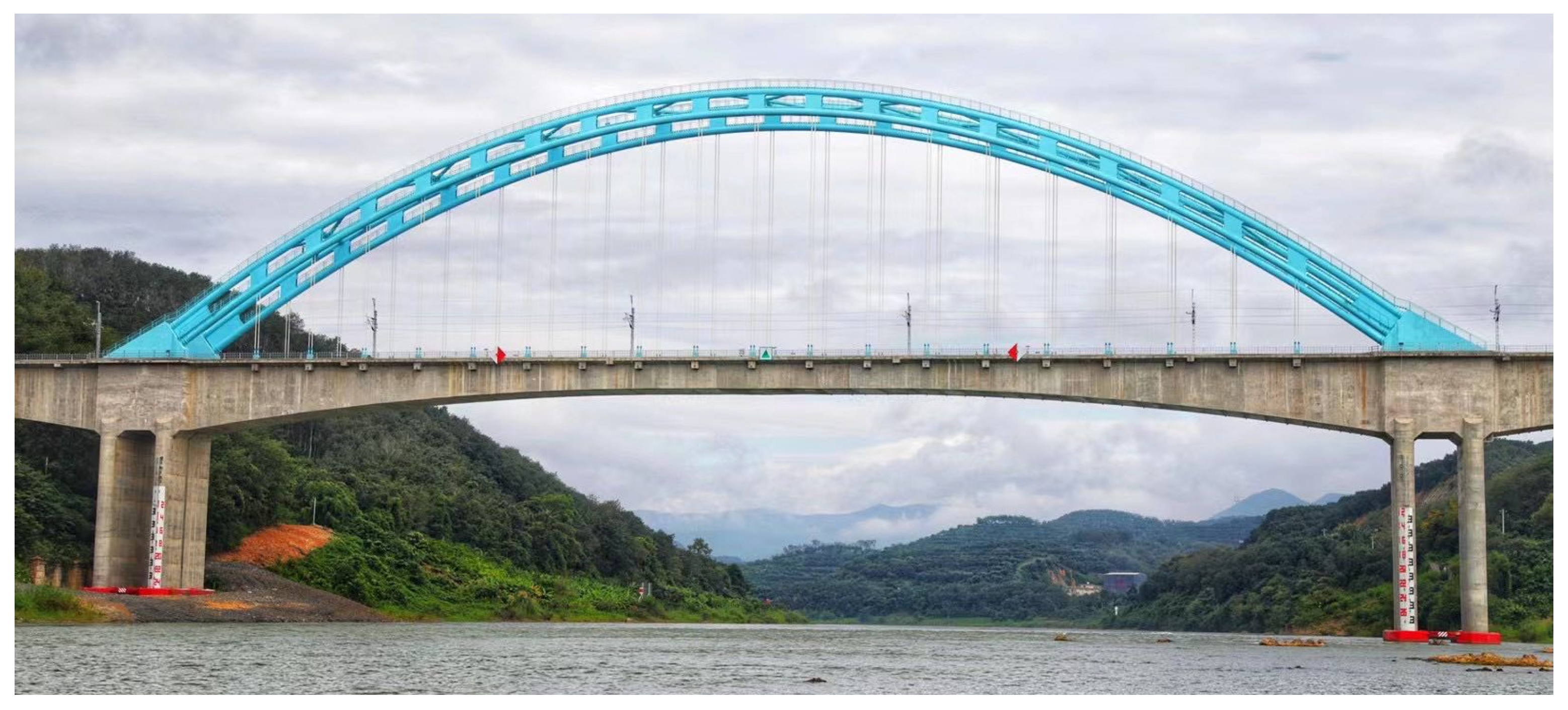
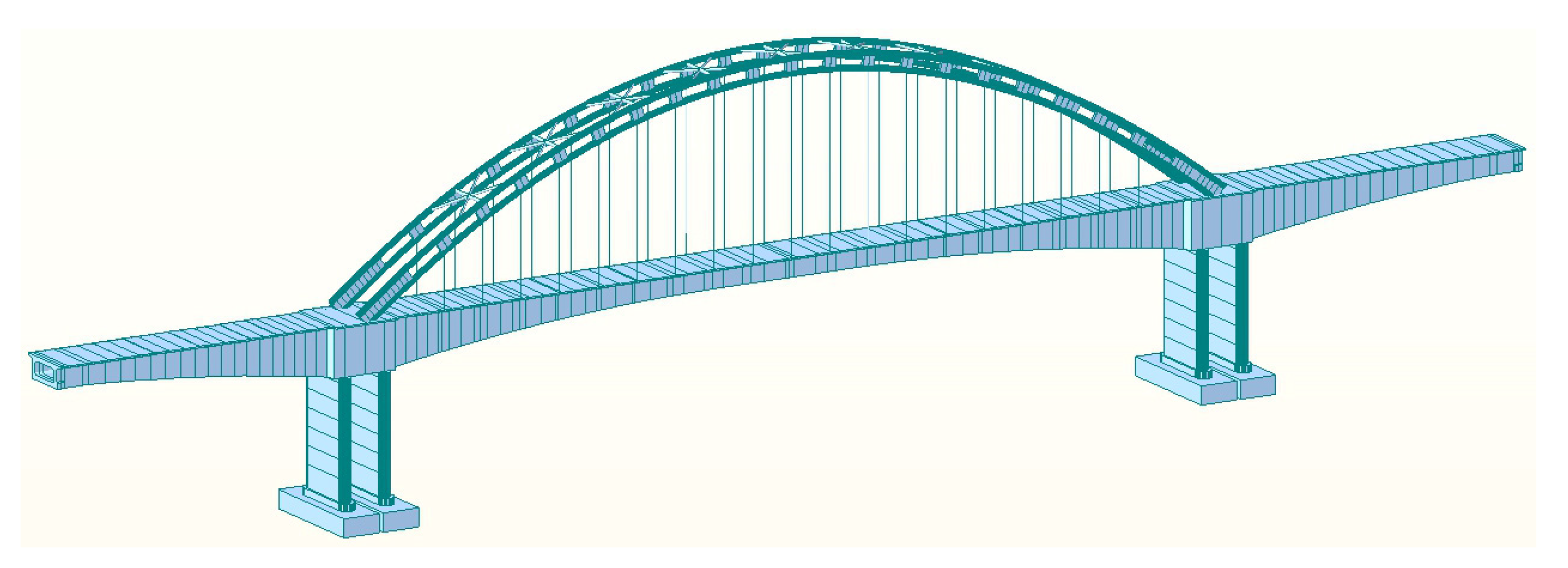
2. Bridge Description

In the present study, the project involved a prestressed concrete bridge for a high-speed railway with a total length of 340 m. More specifically, the length of the main span was 200 m, and that of the sidespans on both sides was 70 m. The elevation of the bridge is shown in Figure 1. The girder of the bridge was a single-box single-chamber box girder with variable cross-section and variable height, in which there was a group of straight girders with an equal height in the middle of the midspan, with a length of 31 m and a height of 4.5 m. Further, there was also a group of straight girders with an equal height at the end of the sidespan, with a length of 7.4 m and a height of 5.0 m. The girder height at the middle pier reached the maximum value of 11 m, and the girder bottom curve at the variable height section presented a quadratic parabola shape. The thickness of the top plate, bottom plate, and web plate of the girder ranged from 45 cm to 61 cm, 53 cm to 100 cm, and 60 cm to 120 cm, respectively. In the straight section of the side span, the thickness of the bottom plate was found to undergo a gradual transition from 55 cm to 100 cm, while the thickness of the web plate gradually changed from 76.5 cm to 100 cm. These transitions exhibited a discontinuous, or broken-line, pattern. Additionally, the width of the top plate of the girder measured 13.0 m, with a localized increase to 15.4 m at the central bearing point. The bottom plate had a width of 9.8 m.
The girder was provided with prestressed tendons in the longitudinal, transverse, and vertical directions. The longitudinal prestressing system of the top plate, bottom plate, and web plate was provided with 7- ϕ 15.2 steel strands with high strength and low relaxation. Specifically, the diameter of the steel strand was 15.2 mm, and the standard tensile strength was 1860 MPa. The longitudinal prestressed tendons were perforated with metal corrugated pipes with an inner diameter of 100 mm and an outer diameter of 107 mm, and the spacing between corrugated pipes in the horizontal and vertical directions of the girder was 23 cm. The transverse prestressing system was composed of 4- ϕ 15.2 steel strands, and its standard tensile strength was 1860 MPa. Flat plastic corrugated pipes with a width of 72 mm and a height of 23 mm were perforated and staggered along the box girder with a spacing of 50 cm along the bridge direction. The vertical prestressing system consisted of prestressed concrete special threaded steel bars with a diameter of ϕ 32 mm, and they were perforated with metal corrugated pipes with an inner diameter of 45 mm. The aerial photo of the bridge is shown in Figure 2.

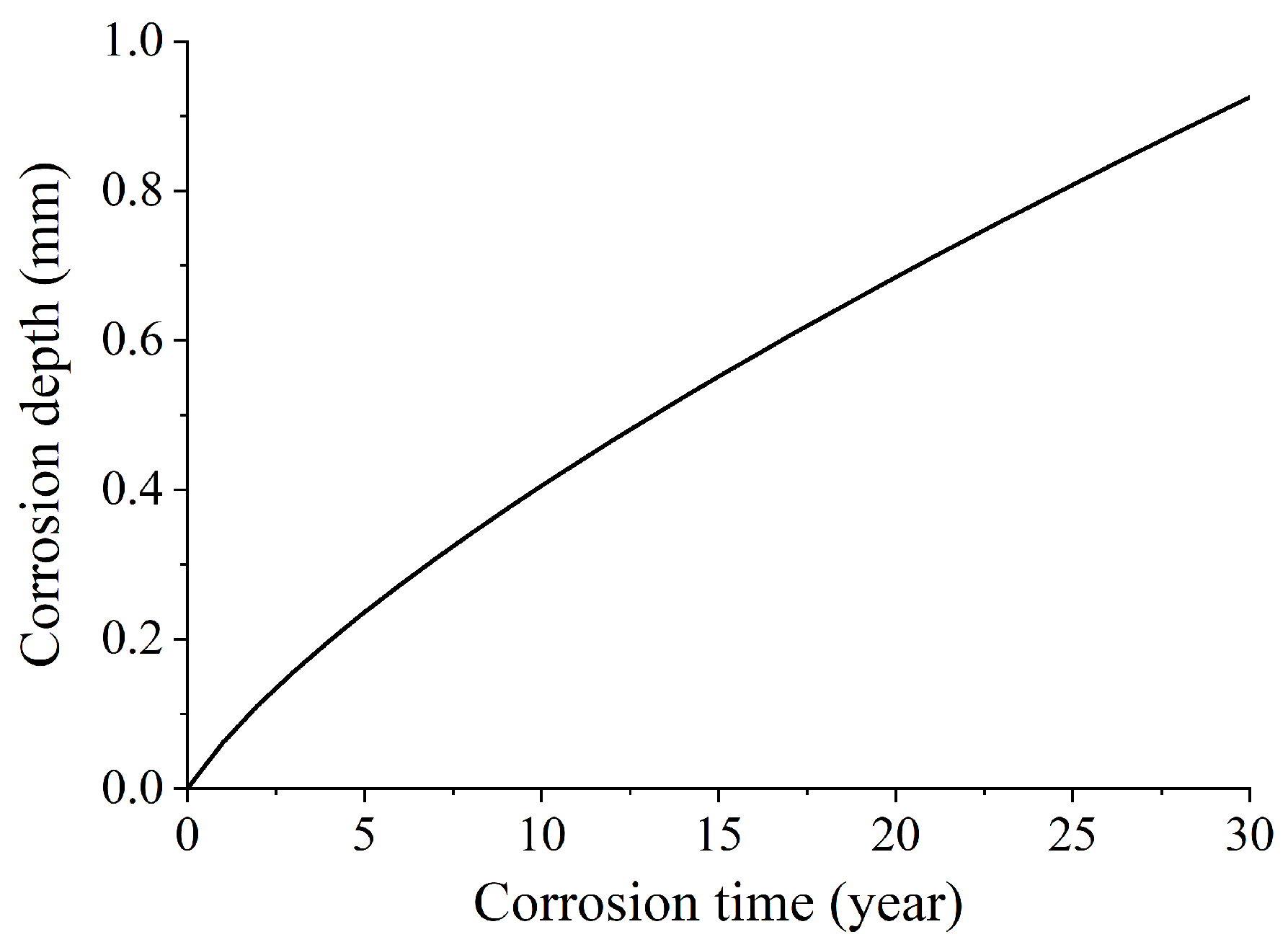
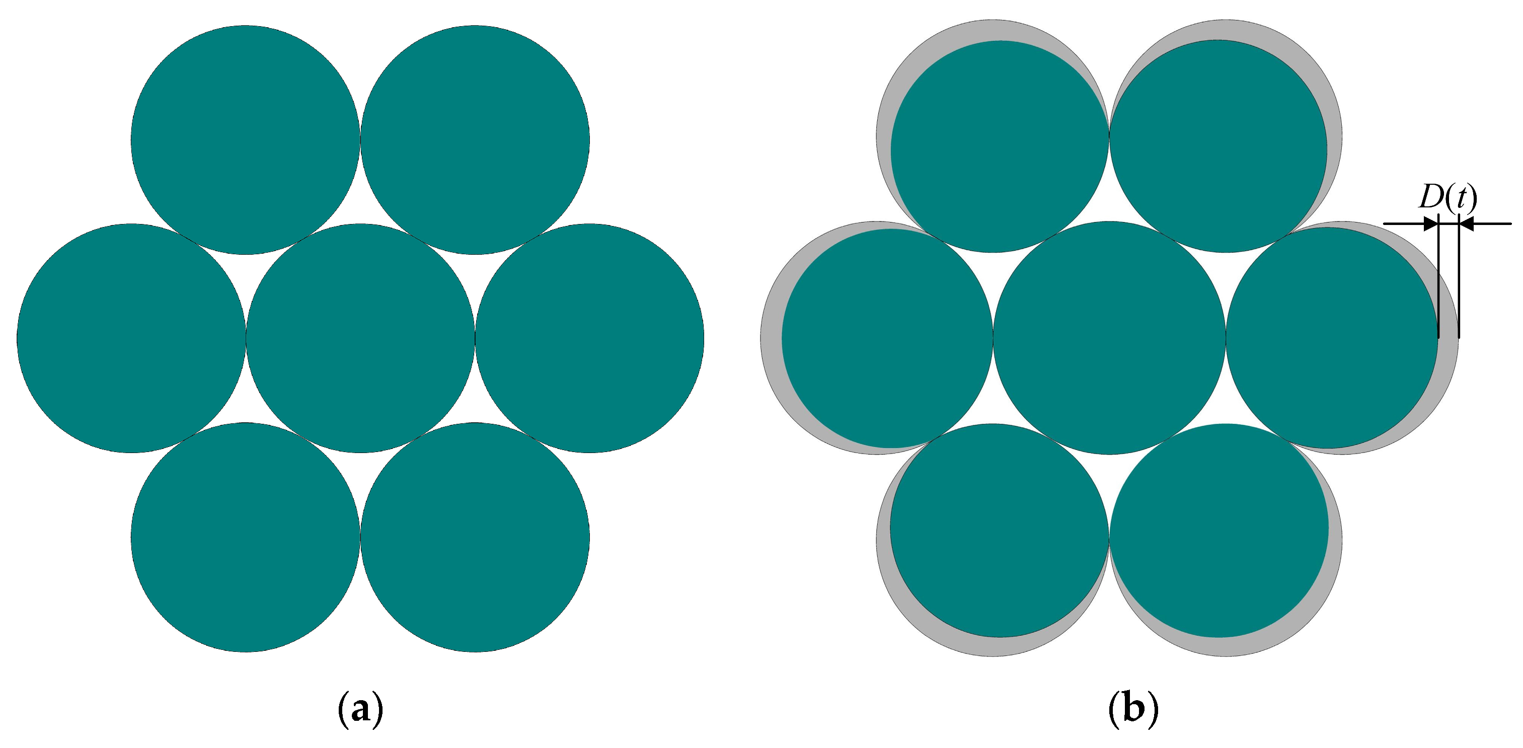
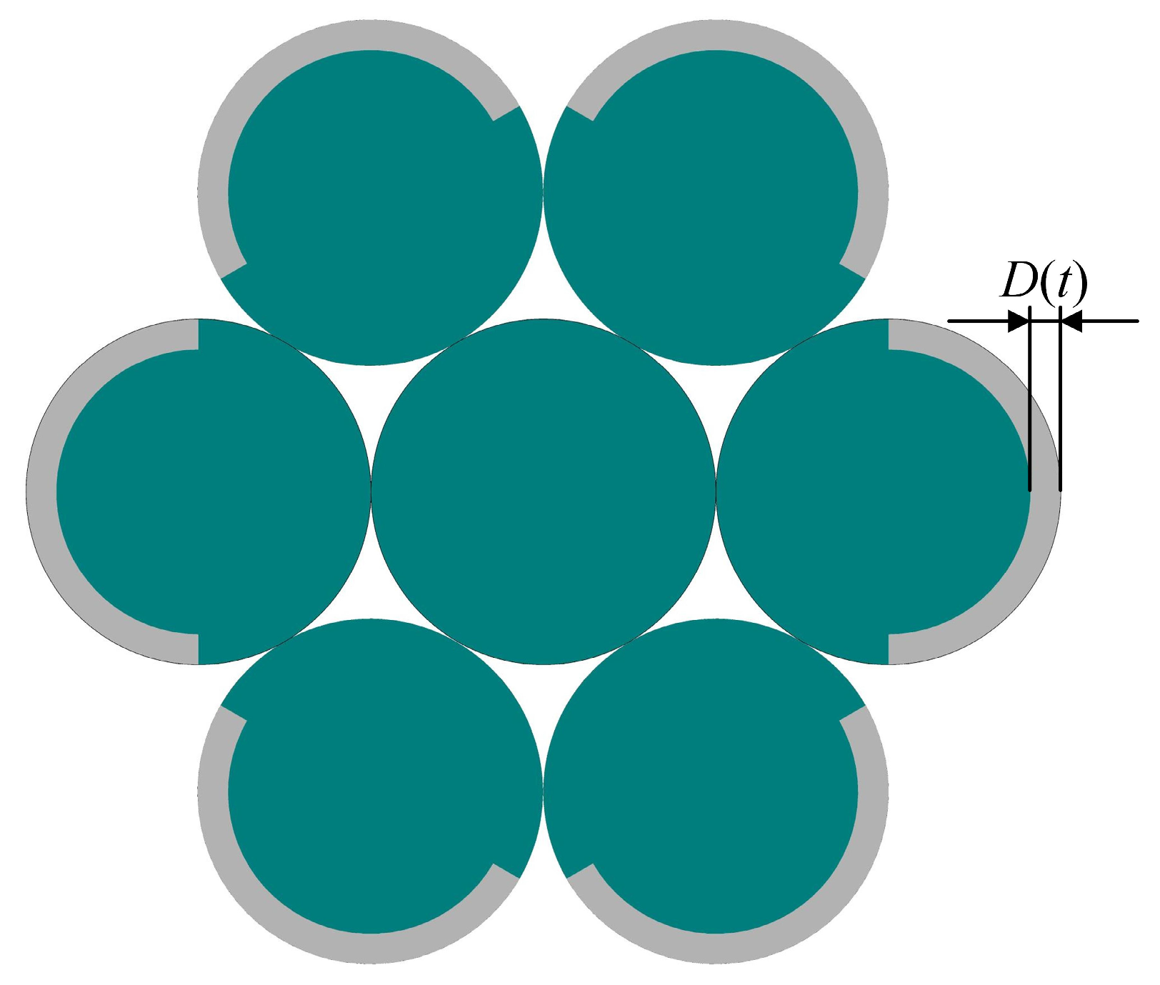
3. Time-Varying Theoretical Model of Steel Strand Corrosion within Grouting Defects

When there are grouting defects in the corrugated pipe, the steel strand will be exposed to the air due to the loss of protection from cement mortar. Under the long-term invasion of water vapor and chloride ions, the steel strands will be in an extremely corrosive environment. When the rust-causing factor reaches a certain level, the steel strand begins to corrode. The corrosion process of steel strands is the electrochemical reaction of iron atoms to generate iron ions. The rate of the electrochemical reaction determines the corrosion rate of the steel strands, and the corrosion current density on the steel strands can characterize the rate of the electrochemical reaction. The greater the current density, the faster the electrochemical reaction rate and the faster the corrosion rate of the steel strands. The time point when the corrosion begins is referred to as the initial corrosion time, and the current density of the corresponding steel strand at this time point is denoted as the initial corrosion current density, which is related to the water/cement ratio of concrete and the concrete cover thickness of the steel strand. The specific formula can be expressed as follows [25,26]:
i c c o r ( t 0 ) = 37.8 ( 1 w / c ) 1.64 C
where i c o r r ( t 0 ) represents the initial corrosion current density (μA/cm2); t 0 represents the initial corrosion time (year); w / c represents the water/cement ratio of concrete outside the steel strand; and C represents the concrete cover thickness of the steel strand (cm).
Following the onset of corrosion, the presence of corrosion products on the surface of steel strands impedes the diffusion of iron ions, causing a gradual reduction in corrosion current density. Vu et al. [27] elucidated this relationship between current density and time following the initiation of corrosion through extensive experimental data, which can be represented as follows:
i c c o r ( t ) = i c c o r ( t 0 ) 0.85 ( t t 0 ) 0.29
The steel strands within grouting defects are left exposed in the defect cavity once grouting is finished, rendering them susceptible to corrosion. As a result, it is plausible to simplify the initial corrosion time t 0 = 0 , namely, Formula (2), as follows:
i c c o r ( t ) = i c c o r ( t 0 ) 0.85 t 0.29
when the corrosion type is assumed to be uniform corrosion, the corrosion rate of steel strands is related to the current density. According to the empirical formula, the relationship between both can be expressed as follows [27]:
s ( t ) = 0.0116 i c c o r ( t )
where s ( t ) represents the corrosion rate of steel strands (mm/year), and i c o r r ( t ) represents the corrosion current density (μA/cm2).
In the present study, the water/cement ratio of girders was 0.34, the minimum concrete cover thickness of steel strands was 12 cm, and the initial corrosion current density i c o r r ( t 0 ) was calculated as 6.23 μA/cm2 according to Formula (1). Then, according to Formulas (3) and (4), the relationship between steel strand corrosion depth and corrosion time can be obtained, as shown in Formula (5) and Figure 3.
D ( t ) = 0 t 0.0116 i c c o r ( t 0 ) 0.85 t 0.29 = 0 t 0.0614 t 0.29
where D ( t ) represents the corrosion depth of steel strands (mm).
The standard seven-wire steel strand adopted in the present study was composed of one central steel wire encompassed by six outer ring steel wires. The diameter ( d 0 ) of the central steel wire was 5.2 mm, and that ( d 1 ) of the outer ring steel wire was 5.0 mm. The cross-section of the steel strand is shown in Figure 4a. The special structure of steel strands serves to shield the central steel wire from corrosion, with only the outer ring steel wires being exposed to the external environment, making them susceptible to corrosion. Additionally, a greater likelihood of exposure to a corrosive environment corresponds to an increased corrosion rate. As such, the corrosion area of steel strands can be expressed as the gray area in Figure 4b. To simplify the calculation, the cross-sectional area of steel strand corrosion was approximately equivalent and analyzed according to Figure 5. In other words, the cross-sectional corrosion rate of each outer ring steel wire can be expressed as follows [28]:
ρ w ( t ) = S c ( t ) S 0 = 1 2 1 2 × 1 D ( t ) r 1 2
where S c ( t ) represents the corrosion cross-sectional area (mm2) of one outer ring steel wire within the corrosion time; S 0 represents the initial cross-sectional area of the outer ring steel wire (mm2); D ( t ) represents the corrosion depth of the outer ring steel wire (mm); and r 1 represents the radius of the outer ring steel wire (mm).
Each individual steel wire within the steel strand has a relatively small cross-sectional area, and a substantial reduction in this cross-sectional area due to localized corrosion can have a pronounced effect on the mechanical properties of the steel wires. Furthermore, being a high-strength material, the steel wire demonstrates clear brittle failure characteristics. Consequently, the ultimate tensile strength of corroded steel strands primarily hinges on the degree of corrosion experienced by each individual steel wire [29]. Jeon et al. [30] conducted several experiments and numerical simulations and found that the nominal ultimate tensile strength of steel strands after corrosion had a linear relationship with the corrosion rate of the section of individual outer steel wire, which can be expressed as follows:
f y n ( t ) = 1995.6 ρ w ( t ) + 1801.6
where f y n ( t ) represents the nominal ultimate tensile strength of steel strands after corrosion (MPa).
By substituting Formulas (5) and (6) into the above formula, the relationship between the nominal ultimate tensile strength and corrosion time of steel strands can be expressed as follows:
f y n ( t ) = 997.8 × 1 0 t 0.02456 t 0.29 2 + 803.8
In the present study, the standard tensile strength of steel strands in the girder was 1860 MPa, and the pre-tensile stress applied to steel strands was 70% of the standard tensile strength, namely 1302 MPa. With the progression of corrosion, the section of steel strands at the defect cavity decreased gradually, which led to a decrease in the nominal ultimate tensile strength ( f y n ( t ) ). When f y n ( t ) decreased to 1302 MPa, the steel strand would break and fail. By substituting f y n ( t ) = 1302   MPa into the above formula, the corrosion depth and corrosion time of the outer ring steel wire when the steel strand was broken can be calculated to be 0.733 mm and 22 years, respectively. Therefore, when grouting defects are present in the girder, the steel strand within the defect would be prone to corrosion, leading to a reduction in its cross-sectional area. Moreover, the corrosion depth would progressively increase, as illustrated in Figure 3. After 22 years of continuous corrosion, the corrosion depth of the outer ring steel wire was projected to reach 0.733 mm. Under such circumstances, the nominal ultimate tensile strength of the steel strand would decrease to the value of the pre-tensile stress. Moreover, the steel strand in the defect cavity may fail, completely losing the precompression effect on the girder.

4. The Finite Element Model of the Prestressed Concrete Bridge

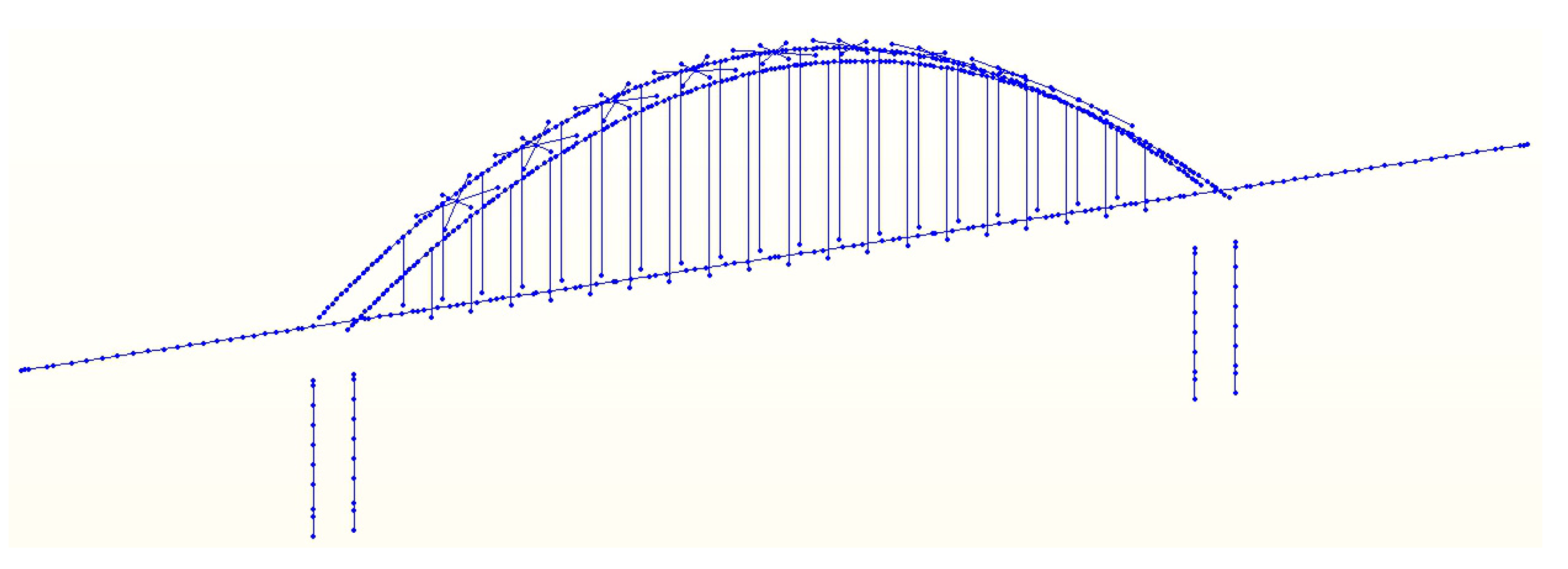
4.1. Construction of the Finite Element Model

In the present study, special bridge analysis software (Midas Civil 2021 V1.2) was used to establish a three-dimensional finite element model of the prestressed concrete bridge [31]. The type of the finite element model was the space beam-column element mode. Among them, the girder, arch ribs, cross braces, bridge piers, and abutments were simulated using beam elements. Each beam element was composed of two nodes. Each node had a total of six degrees of freedom, including three directions of translation and three directions of rotation, and had deformation stiffness under tension, compression, shear, bending, and torsion. The suspension rod was simulated using truss elements that were only subjected to tension, and each truss element was also composed of two nodes, but each node had only three translational degrees of freedom. The interactions between the girder and the arch foots, suspension rods, and bridge piers were simulated using rigid connections. The whole bridge model was composed of 612 nodes and 582 elements, including 544 girder elements and 38 tension-only truss elements. The three-dimensional finite element model and discrete element diagram of the bridge are shown in Figure 6 and Figure 7. The finite element model parameters and the material property setting of the components are listed in Table 1 and Table 2. It should be noted that this study mainly focuses on the performance degradation of the prestressed concrete girder and neglects the effect of the tension force loss of the suspension rods.
In accordance with the original bridge design, a specific quantity of steel strands was placed in both the longitudinal, transverse, and vertical directions of the girders. However, when using Midas Civil, the girder element adhered to the plane section assumption theory, where the cross-sectional stiffness of the girders was exceptionally high; as such, considering transverse and vertical prestress in the model was of limited significance. As a result, only prestressed steel strands in the longitudinal direction were set in the finite element model. In the finite element model of the prestressed concrete bridge, there were 390 longitudinal steel strands in girders, including 60 steel strands for the midspan bottom plate and 6 for the midspan top plate, as well as 16, 104, and 42 steel strands for the bottom plate, top plate, and web plate, respectively, in the left and right sidespans. If the steel strand at a certain site suffered from corrosion due to grouting defects, the cross-section of the steel strand at that site would gradually decrease. Thus, by adding different construction stages in Midas Civil, the cross-section of the steel strand at each construction stage was set according to the curve of the relationship between the corrosion depth and the corrosion time of the steel strand. After sufficient corrosion for a long time, the nominal ultimate tensile strength of the steel strands would decline to the level of the initial pre-tensile stress. Hence, the steel strand would experience failure at the location of the grouting defect, leading to a complete loss of its precompression effect on the girder. In such a scenario, these steel strands were directly treated as being passivated during the corresponding construction stage in the numerical simulation model.

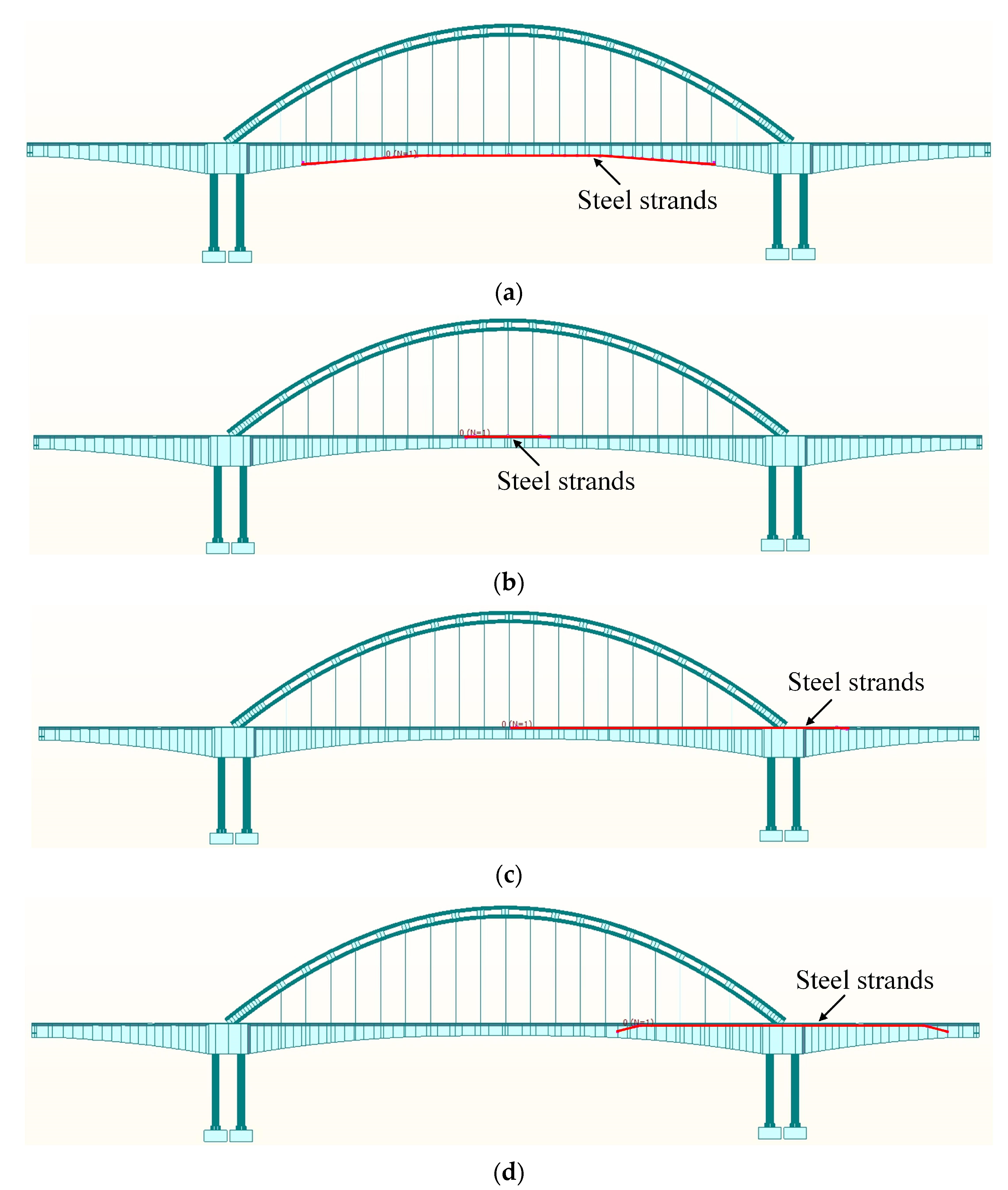
4.2. Corrosion Conditions of Steel Strands in the Girder

A total of 390 bundles of steel strands were utilized in the construction of the girders, distributed in the top plate, bottom plate, and web plate, with each bundle comprising 19 independent seven-wire steel strands. In instances where grouting defects were identified within the corrugated pipes, the 19 steel strands located at the defect cavity will corrode independently, following the established time-varying model. As such, the corrosion status considered in the present study was established on a per-bundle steel strand basis. Notably, the primary role of the cement paste within the corrugated pipe was corrosion protection for the steel strands, having minimal impact on their prestress performance. Therefore, once the steel strand within the defect cavity was broken due to corrosion, it was considered that the whole steel strand failed and no longer exerted precompression effects on the concrete structure. The steel strands in the concrete of the left and right sidespans of the girder were symmetrically distributed, exerting the same influence on the bridge after corrosion. Given that fact, only the steel strands in the right sidespan were explored in the present study. The corrosion parameters of each steel strand are listed in Table 3, and the positions of the steel strands in the midspan bottom plate, the midspan top plate, the right-sidespan top plate, and the right-sidespan web plate is shown in Figure 8.

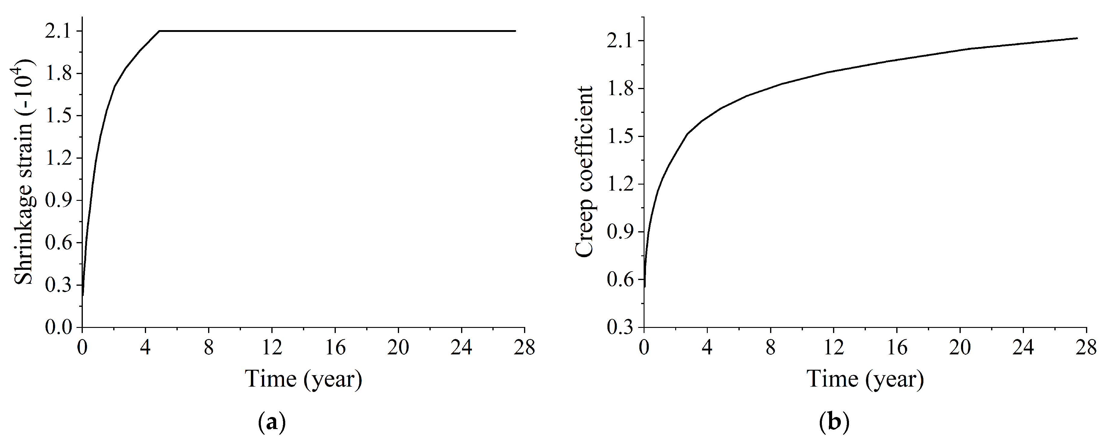
4.3. Shrinkage and Creep of Concrete

Even in the absence of corrosion in the girder’s steel strand, the long-term effects of concrete shrinkage and creep can result in the relaxation of the internal steel strand. This relaxation phenomenon has the potential to diminish the precompression effect that the steel strand imparts to the concrete. At the same time, due to the constraint effect of ordinary steel bars in the concrete, the development of shrinkage and creep will also cause stress redistribution in the structure. Thus, the effect of concrete shrinkage and creep on the structure cannot be ignored in the analysis of the influence of steel strand corrosion on the performance of bridges [32]. Shrinkage is an inherent property of concrete, which is a physical and chemical phenomenon of volume reduction caused by factors such as moisture changes, chemical reactions, and temperature changes in concrete. It is related to moisture, temperature, admixtures, and curing environment of the concrete and is independent of the structural load. The creep is also an inherent property of concrete, which refers to the phenomenon where the deformation of concrete structures increases over time under sustained loads. The influence of concrete creep on the structure has a double-sided effect. On the one hand, for prestressed concrete structures, creep will cause the loss of prestress and increase the deflection of the bridge. On the other hand, creep can also reduce the temperature stress caused by the hydration heat of concrete and improve the stress peak at the location of structural stress concentration. The evolution of concrete’s shrinkage and creep phenomena over time is commonly elucidated through the quantification of shrinkage strain and the creep coefficient. In Midas Civil, only the concrete strength, environmental relative humidity, structural thickness, and material age of concrete at the beginning of shrinkage were set; the relationship curve of the shrinkage strain and creep coefficient with time could be automatically plotted, as shown in Figure 9.

5. Performance Degradation Analysis of Prestressed Concrete Girders with Grouting Defects

5.1. Influence of Steel Strand Corrosion on the Vertical Displacement of Girders

5.1.1. Changes in the Midpoint Vertical Displacement of the Girder over Corrosion Time

For prestressed concrete bridges, it is common for the midpoint to represent the structurally weakest point of the girder. Notably, this location often exhibits significant vertical displacement when subjected to unpredictable damage [33,34]. Hence, the impacts of concrete shrinkage, creep, and the corrosion of steel strands on the midpoint vertical displacement of the girder needed to be analyzed. As shown in Figure 10, when there was only shrinkage and creep of concrete, the downward vertical displacement in the midpoint region of the girder gradually increased with time, and the increasing rate of the displacement became progressively smaller. The traffic load was applied on the girder on the first day after the construction of the bridge was completed, which led to a large change in the midpoint vertical displacement. The midpoint vertical displacement of the girder, attributable to concrete shrinkage and creep, exhibited minimal change five years following the construction of the bridge. Under Conditions 1, 2, and 3, corrosion existed in eight bundles of steel strands in the midspan bottom plate of the girder, and the length of steel strands increased in turn. The steel strands failed and broke under the combined influence of corrosion and pre-tensioning, occurring 22 years after the construction of the bridge. As a result, there was a sudden and substantial increase in the downward vertical displacement within the midpoint region of the girder. Meanwhile, the longer the length of the steel strand, the smaller the vertical displacement variation at the midpoint. The downward vertical displacement change values in the midpoint region of the girder under Conditions 1, 2, 3, and 4 were 8.59 mm, 6.24 mm, 1.26 mm, and 17.55 mm, respectively. These changes were observed in comparison to the effects of concrete shrinkage and creep 30 years after the construction of the bridge. The corroded steel strands under Condition 5 were located in the midspan top plate of the girder, and the bending moment resulting from the precompression of steel strands on the concrete was opposite to that on the bottom plate. Hence, the downward vertical displacement in the midpoint region of the girder caused by the shrinkage and creep of concrete decreased under the action of the steel strand corrosion on the midspan top plate.

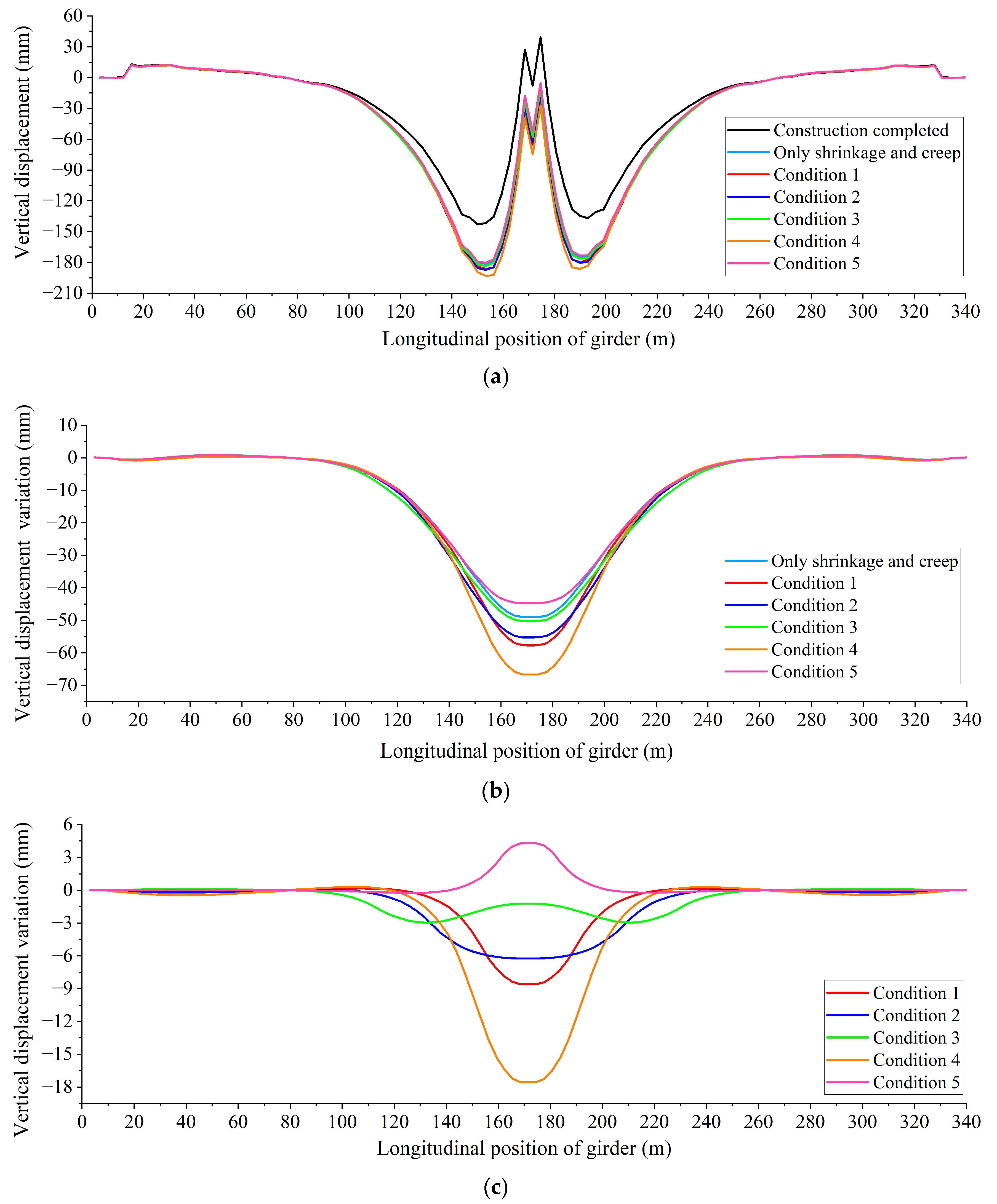
5.1.2. Influence of Steel Strand Corrosion on the Vertical Displacement Distribution of the Girder

The vertical displacement distribution of the bridge girder observed 30 years post-construction was found to be influenced by the effects of concrete shrinkage, concrete creep, and the corrosion of steel strands. Figure 11 illustrates this phenomenon. Compared with the impact of concrete shrinkage and creep only, distinct alterations in the vertical displacement distribution curve of the girder were discernible under various midspan steel strand corrosion conditions. Predominantly, these displacement changes manifested within the midpoint region of the girder. By subtracting the initial post-construction vertical displacement from the vertical displacement caused by the concrete shrinkage and creep and steel strand corrosion of Conditions 1–5 in Figure 11a, the distribution of vertical displacement change values that occurred over a 30-year period following the bridge’s construction could be obtained, as illustrated in Figure 11b. Under all working conditions, the maximum change value of the downward vertical displacement could be observed in the midpoint of the girder, and the change value gradually decreased from the midpoint of the girder to both sides. However, there was no significant change in the vertical displacement far away from the midpoint region of the girder. Compared with the shrinkage and creep of concrete only, the corroded steel strand under Conditions 1–4 was located at the midspan bottom plate, leading to an increase in the downward vertical displacement change value. In contrast, the corroded steel strand was located at the midspan top plate under Condition 5, which caused a decrease in the downward vertical displacement change value.
By subtracting the vertical displacement change values resulting from the effects of concrete shrinkage and creep from those observed under Conditions 1–5 in Figure 11b, the vertical displacement change value specifically attributable to steel strand corrosion over the 30-year period following the construction of the bridge could be isolated, as shown in Figure 11c. An observation can be made that the midspan steel strand corrosion only affected the midspan vertical displacement of the girder, while the sidespan vertical displacement of the girder hardly changed. Through a comparison of the vertical displacement distribution curves under Conditions 1–3, the length of corroded steel strands was found to affect the range and size of vertical displacement of the girder. The relationship between the length of steel strands and the vertical displacement change of the girder was as follows: as the length of the steel strands increased, the range of vertical displacement change of the girder became larger, and there was a more significant vertical displacement change observed at locations farther away from the midpoint region, whereas the vertical displacement change value in the midpoint region tended to be smaller. In some cases, Condition 3 would even lead to a rebound in vertical displacement in the midpoint region. Comparing the vertical displacement distribution curves under Conditions 1 and 4, it is evident that the vertical displacement change range of the girder, caused by the corrosion of steel strands of the same length, remained essentially consistent. Moreover, an increase in the number of corroded steel strands resulted in a larger vertical displacement change value throughout the girder.
Due to the comparable impact of steel strand corrosion on the vertical displacement of the girder observed between the right-side span top plate and the right-side span web plate, the steel strand corrosion on the right-side span web plate was selected for analysis. Figure 12 illustrates the distribution curve of vertical displacement change values in the girder resulting from steel strand corrosion, specifically on the right-side span web plate over a 30-year period following the construction of the bridge. Downward vertical displacement changes can be observed in both the midspan and the right sidespan of the girder. Further, the vertical displacement change value of the midspan was far larger than that of the right sidespan. However, there was no significant change in the vertical displacement at the pier. Through a comparison of the vertical displacement change value distribution curves under Conditions 9–11, an observation can be made that with an increase in the length of corroded steel strands, the vertical displacement change range of the girder became larger in turn, and the peak value of vertical displacement changes of the midspan and the right sidespan moved to both sides. Notably, under all working conditions, the maximum vertical displacement change resulting from steel strand corrosion consistently occurred at the midspan of the girder. Further, the longer the steel strand, the larger the maximum vertical displacement change value.

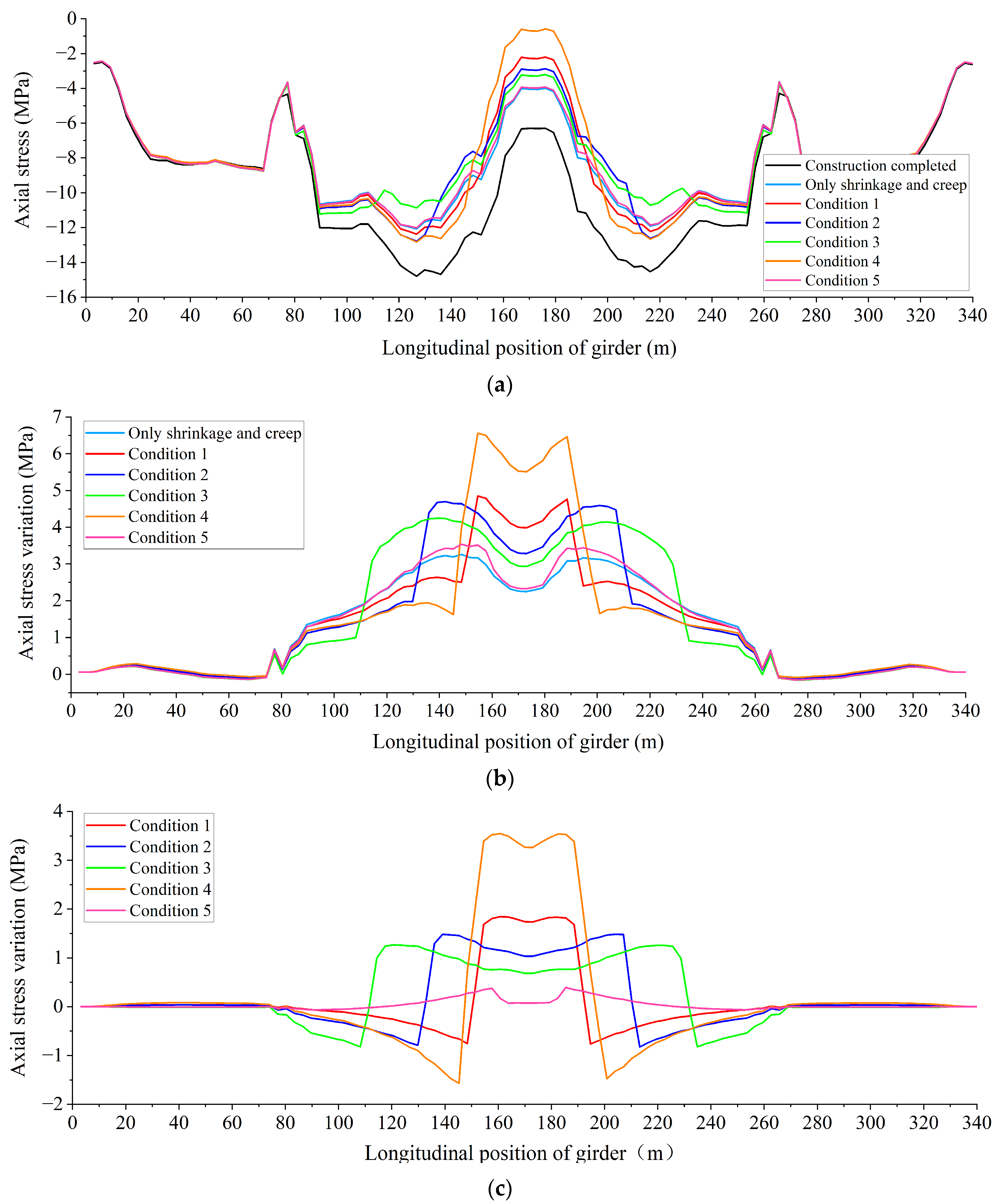
5.2. Influence of Steel Strand Corrosion on the Axial Stress of Girders

Considering that the steel strands were primarily distributed at the bottom plate of the girder [35], this section focuses on the analysis of the axial stress distribution and changes in the bottom plate of the girder 30 years after the construction of the bridge, taking into account the effects of concrete shrinkage, creep, and steel strand corrosion. As shown in Figure 13a, as many prestressed tendons were arranged in the midspan bottom plate of the girder, the axial compressive stress of the midspan bottom plate was larger than that of the sidespan bottom plate after the construction of the bridge. Moreover, the axial stress distribution of the midspan bottom plate was W-shaped, and the axial compressive stress of the bottom plate at the midpoint and pier positions was small. Under the influence of shrinkage and creep of concrete, the axial compressive stress of the midspan bottom plate of the girder decreased, while the axial compressive stress of the sidespan bottom plate of the girder remained basically unchanged. Under the steel strand corrosion at the midspan, the axial compressive stress of the midspan bottom plate further decreased, and that in the midpoint of the girder under Condition 4 decreased to 0.79 MPa.
By subtracting the initial post-construction axial stress from the axial stress caused by the concrete shrinkage and creep and steel strand corrosion of Conditions 1–5 in Figure 13a, the distribution of axial stress change values that occurred over a 30-year period following the bridge’s construction could be obtained, as illustrated in Figure 13b. Since the pre-camber was pre-imposed in the midpoint region of the girder, the maximum axial stress change value of the bottom plate of the girder under the action of shrinkage and creep of concrete did not appear in the midpoint region but at the positions 150 m and 190 m on both sides of the pre-camber. Under Condition 4, the axial stress change value of the bottom plate caused by steel strand corrosion was the largest, reaching 6.56 MPa.
By subtracting the axial stress change values resulting from the effects of concrete shrinkage and creep from those observed under Conditions 1–5 in Figure 13b, the axial stress change value specifically attributable to steel strand corrosion over the 30-year period following the construction of the bridge could be isolated, as shown in Figure 13c. Under steel strand corrosion in the midspan bottom plate from Conditions 1 to 4, within the steel strand length range, the bending moment induced by corrosion and the axial stress caused by axial force had the same effect, so steel strand corrosion led to a reduction in the axial compressive stress experienced by the bottom plate. Beyond the specified steel strand length range, the direction of axial stress caused by the bending moment becomes reversed, and the expansion of concrete within the range of steel strands exerts compressive stress on the adjacent concrete. As such, both the axial stress caused by the bending moment and axial force reversed their effects simultaneously. Thus, as shown in Figure 13c, the axial compressive stress decreased within the corroded steel strand length range, while the axial compressive stress increased on both sides outside the steel strand length range. Further, the increase in axial compressive stress was notably most significant at the end of the steel strand, demonstrating a gradual decrease in magnitude towards both sides. This trend persisted until reaching the pier, where the axial compressive stress increase value diminished to zero. A comparison of the axial stress change curves under Conditions 1–3 reveals several noteworthy patterns. Notably, as the length of corroded steel strands increased, the range of axial compressive stress reduction in the bottom plate widened, and the actual reduction in the axial compressive stress value diminished. Concurrently, there was a notable increase in the compressive stress within the concrete on both sides of the corroded steel strands. When comparing the axial stress change curves under Conditions 1 and 4, it became evident that, with an identical length of corroded steel strands, the affected area of the bottom plate remained essentially constant. Nevertheless, a greater number of corroded steel strands amplified their impact on the axial stress of the midspan bottom plate. Under Condition 5, the corroded steel strand was located in the midspan top plate. In the steel strand length range, the axial stress caused by the corrosion and bending moment was opposite in the bottom plate, but the tensile stress caused by the axial force was in a dominant position. Hence, even if there was a mutual offset, the axial compressive stress of the bottom plate of the girder would still decrease. Beyond the specified steel strand length range, the direction of axial stress caused by corrosion and bending moment becomes reversed simultaneously. Nonetheless, under this condition, the axial stress caused by axial force remained relatively low, while the tensile stress induced by the bending moment took on a dominant role. As such, the axial compressive stress in the bottom plate of the girder is still decreasing. Further, the axial stress change value gradually diminished towards both sides, ultimately reaching zero at the pier.

5.3. Performance Degradation Summary of Prestressed Concrete Girders

Under the effects of concrete shrinkage, creep, and corrosion of steel strands at the midspan bottom plate, noticeable downward vertical displacement becomes apparent at the midpoint of the girder. When corrosion affected 16 bundles of steel strands within the midspan bottom plate, the vertical displacement change in the midpoint of the girder amounted to 17.55 mm over a span of 30 years following the construction of the bridge. The shrinkage and creep of concrete and the corrosion of steel strands weakened the midspan axial compressive stress of the girder. Under the combined action of the shrinkage and creep of concrete and the corrosion of 16 bundles of steel strands, the axial compressive stress in the midpoint of the girder experienced a reduction from 6.30 MPa to 0.79 MPa over a period of 30 years subsequent to the construction of the bridge.

6. Preventive Maintenance Measures for Degraded Prestressed Concrete Girders

At present, the commonly used methods for bridge reinforcement mainly include the pasted steel plate reinforcement method, the enlarged cross-section and reinforcement reinforcement method, and the external prestressing reinforcement method. Among them, the external prestressing method is an active reinforcement technology for the original structure, which aims to restore and improve the performance of the girder by applying steel strands of different lengths, quantities, and pre-tension forces outside the structure. In view of the performance degradation of the bridge due to grouting defects and steel strand corrosion, the specific steps of the reinforcement scheme based on the external prestressing method are as follows:
  • Based on ultrasonic testing, impact echo analysis, or other defect detection methods, a comprehensive inspection of the grouting defects in the corrugated pipes inside the girder is carried out to determine the possible location and specific size of the defect cavities.
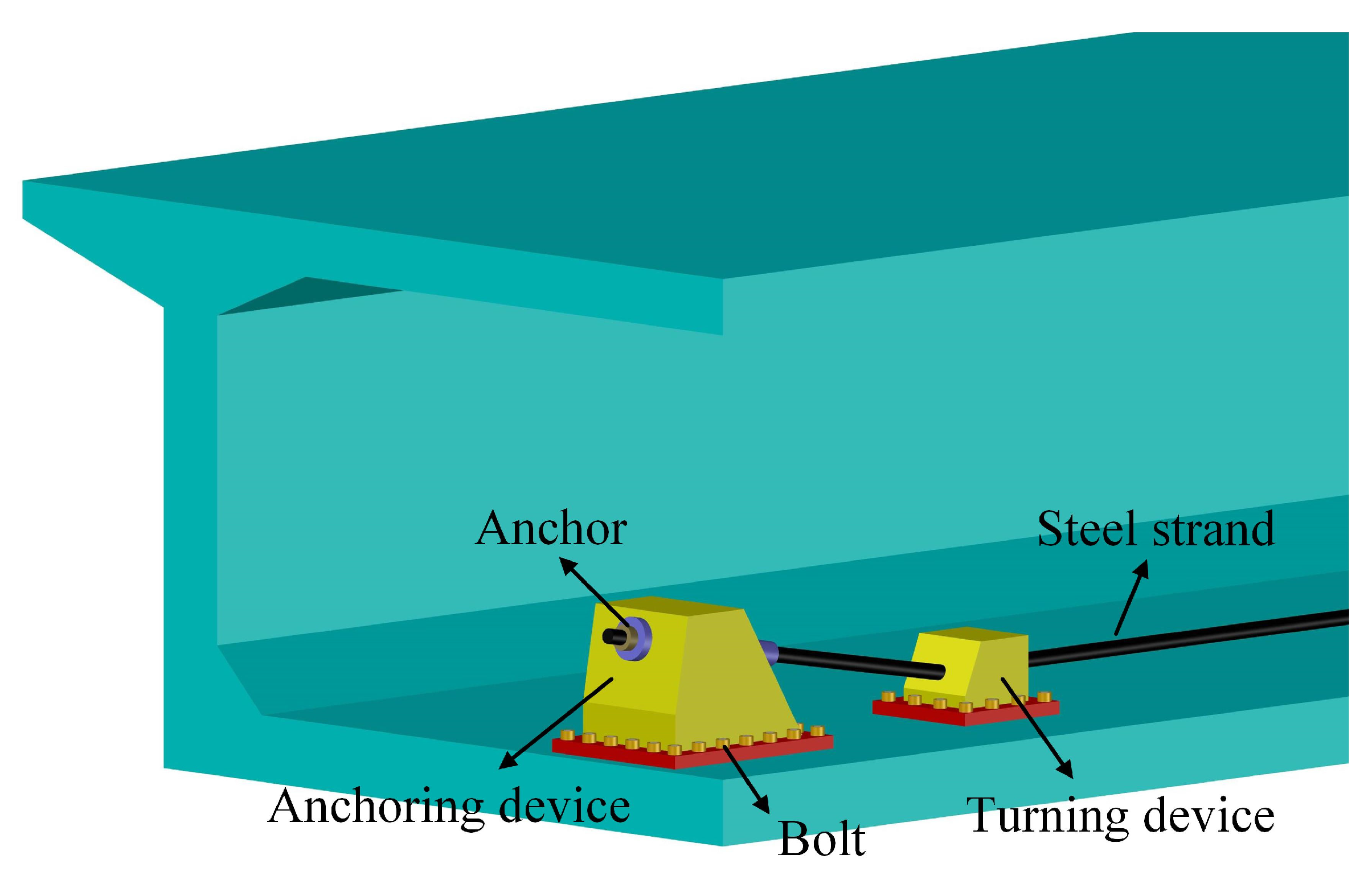
  • Based on the defect detection results, the position and length of the corroded steel strands are counted, and the specific location of the external prestressed reinforcement to be installed is specified. Furthermore, steel anchoring devices and turning devices are installed at both ends of the predetermined position mentioned above, as shown in Figure 14. Among them, the anchoring device is fixed to the girder with high-strength bolts, forming a stable connection between the anchor block and the girder, responsible for directly transferring the external prestress to the girder. The function of the turning device is to provide turning support for the external prestressed reinforcement that undergoes directional turning and to transfer the vertical force of the external prestressed reinforcement to the girder.
  • Install prestressed corrugated pipes at the predetermined positions of the steel strands between the anchoring devices and reserve grouting holes and exhaust holes. Then, insert the same number of steel strands into the corrugated pipes as those that corroded and failed in the girder. Install steel strand anchors on the anchoring device, and use tensioning equipment to tension both ends of the steel strand at the same time. It should be noted that the external pretension force is consistent with the steel strand in the girder.
  • Monitor the structural performance of the reinforced girder to determine whether the expected reinforcement goals are achieved. If not, further measures can be made by adjusting the pre-tension force of the steel strands or continuing to add external prestressed steel strands.
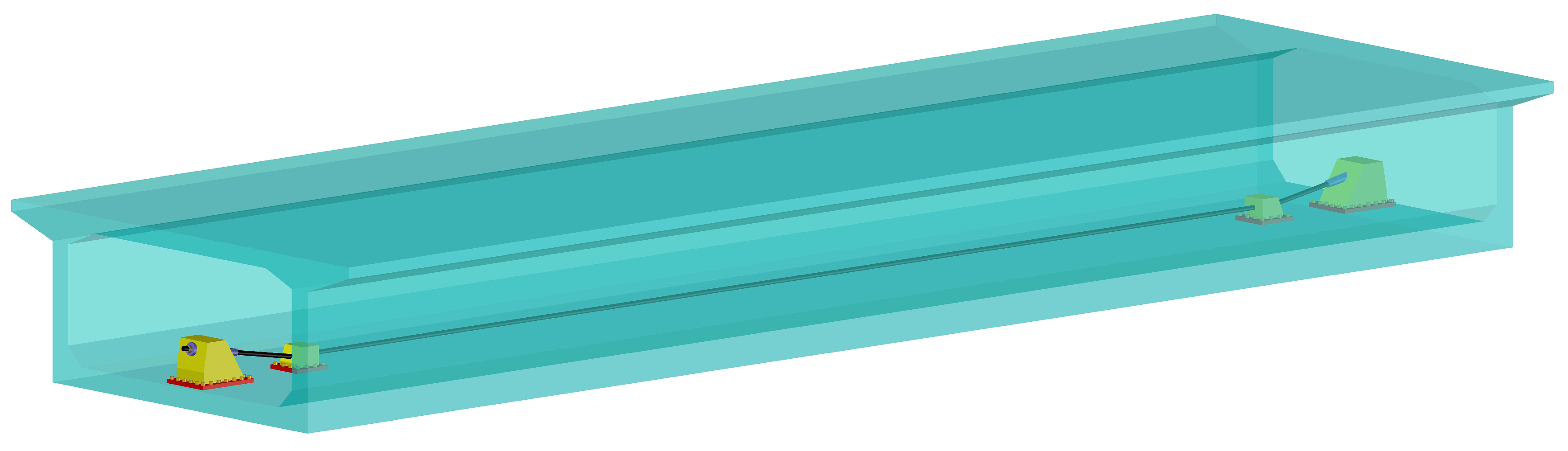
  • If the monitoring results reach the expected target, cement slurry can be injected into the corrugated pipe through the grouting hole to protect the steel strands; the reinforced external stress system is shown in Figure 15.

7. Conclusions

The aim of the present study was to explore corrugated pipe grouting defects in a prestressed concrete bridge. The distribution and changes of the vertical displacement and axial stress of the girder were calculated after taking into account the influence of shrinkage and creep of concrete and steel strand corrosion conditions. The main conclusions are summarized as follows.
  • Due to the combined effects of concrete shrinkage, creep, and the corrosion of steel strands at the midspan bottom plate, a noticeable downward vertical displacement becomes apparent at the midspan of the girder. Further, the magnitude of vertical displacement change progressively escalates from the extremities of the midspan towards the midpoint region. Specifically, under the influence of corrosion affecting 16 bundles of steel strands within the midspan bottom plate, the vertical displacement change in the midpoint of the girder amounted to 17.55 mm over a span of 30 years following the construction of the bridge.
  • The shrinkage and creep of concrete and the corrosion of steel strands weakened the midspan axial compressive stress of the girder. Under the combined action of shrinkage and creep of concrete and corrosion of 16 bundles of steel strands, the axial compressive stress in the midpoint of the girder experienced a reduction from 6.30 MPa to 0.79 MPa over a period of 30 years subsequent to the construction of the bridge.
  • The results reveal that two indicators of vertical displacement and axial stress can be employed to evaluate the performance degradation of prestressed concrete bridges with grouting defects. These findings can provide a reference for the operation and management of bridges with grouting defects.
  • In the current research, the corrosion of steel strands was assumed to be uniform, and only displacement and stress were selected as the main indicators for bridge performance degradation assessment. In order to expand its applicability, we will consider more steel strand corrosion types (such as pitting corrosion) and evaluation indicators for bridge performance degradation (such as structural stiffness and vibration characteristics) in future research. Moreover, the performance degradation evaluation method regarding grouting defects in the girder is also applicable to existing old long-span prestressed concrete bridges (without hangers), and it will become our future research topic.

Author Contributions

Conceptualization, S.G.; methodology, S.G.; software, S.G.; validation, X.F.; formal analysis, K.C.; investigation, S.G.; resources, X.F.; data curation, S.G.; writing—original draft preparation, S.G.; writing—review and editing, F.S.; visualization, F.S.; supervision, K.C.; project administration, X.F.; funding acquisition, S.G. All authors have read and agreed to the published version of the manuscript.

Funding

This research was funded by the China Postdoctoral Science Foundation (2023M733315).

Data Availability Statement

Data are contained within the article.

Conflicts of Interest

Author Shilin Gong was employed by the company Power China Huadong Engineering Corporation Limited. The remaining authors declare that the research was conducted in the absence of any commercial or financial relationships that could be construed as a potential conflict of interest.

Abbreviations

ϕ
diameter
t 0
initial corrosion time
t
corrosion time
i c o r r
corrosion current density
w / c
Water/cement ratio of concrete
C
concrete cover thickness of the steel strand
s
corrosion rate of the steel strand
D
corrosion depth of the steel strand
d 0
diameter of the central steel wire of the steel strand
d 1
diameter of the outer ring steel wire of the steel strand
S c
corrosion cross-sectional area of one outer ring steel wire
S 0
initial cross-sectional area of the outer ring steel wire
r 1
radius of the outer ring steel wire
ρ w
cross-sectional corrosion rate of each outer ring steel wire
f y n
nominal ultimate tensile strength of the steel strand

References

  1. Xiang, Y.Q.; Zhu, S.; Zhao, Y. Research and development on accelerated bridge construction technology. China J. Highw. Transp. 2018, 31, 1–27. [Google Scholar]
  2. Zia, A.; Zhang, P.; Holly, I.; Prokop, J. Sustainability enhancement through high-dose recycled tire steel fibers in concrete: Experimental insights and practical applications. Sustainability 2023, 15, 15760. [Google Scholar] [CrossRef]
  3. Lehner, P.; Hrabová, K. Evaluation of degradation and mechanical parameters and sustainability indicators of zeolite concretes. Constr. Build. Mater. 2023, 371, 130791. [Google Scholar] [CrossRef]
  4. El-Gamal, S.; El-Khouly, H.; Fayek, S.; Mohamed, M.; Roupheil, G.; Aly, N.; Ghaly, A.A.; Breakah, T.; Abou-Zeid, M.N. Enhancing sustainability: Integrating carbon dioxide into Portland cement concrete. Innov. Infrastruct. Solut. 2023, 8, 278. [Google Scholar] [CrossRef]
  5. Jiang, T.; Zheng, J.; Huo, L.; Song, G. Finite element analysis of grouting compactness monitoring in a posttensioning tendon duct using piezoceramic transducers. Sensors 2017, 17, 2239. [Google Scholar] [CrossRef] [PubMed]
  6. Li, B.; Fang, H.; He, H.; Yang, K.; Chen, C.; Wang, F. Numerical simulation and full-scale test on dynamic response of corroded concrete pipelines under multi-field coupling. Constr. Build. Mater. 2019, 200, 368–386. [Google Scholar] [CrossRef]
  7. Zheng, J.; Du, H.; Mu, T.; Liu, J.; Qin, D.; Mei, G.; Tu, B. Innovations in design, construction, and management of Pingnan Third Bridge—The largest-span arch bridge in the world. Struct. Eng. Int. 2022, 32, 134–141. [Google Scholar] [CrossRef]
  8. Huang, S.-G.; Zhang, T.; Cao, H. A calculation model of grout migration height for post-grouting technology. Appl. Sci. 2022, 12, 6327. [Google Scholar] [CrossRef]
  9. Li, N.; Cao, M.; Du, H.; He, C.; Wu, B. Detection of single steel strand distribution in grouting duct based on capacitive sensing technique. Sensors 2019, 19, 2564. [Google Scholar] [CrossRef]
  10. Chen, X.; Xu, L.S.; Xu, M. Adaptive control system for grouting pressure stability based on fuzzy algorithm. J. Intell. Fuzzy Syst. 2016, 31, 2231–2239. [Google Scholar] [CrossRef]
  11. Chen, W.; Liu, Y.; Wu, J.; Lu, S.; Han, G.; Wei, X.; Gao, Y. Enhancing cementitious grouting performance through carbon nanotube-coated fly ash incorporation. Constr. Build. Mater. 2023, 409, 133907. [Google Scholar] [CrossRef]
  12. Jiang, T.; Kong, Q.; Wang, W.; Huo, L.; Song, G. Monitoring of grouting compactness in a post-tensioning tendon duct using piezoceramic transducers. Sensors 2016, 16, 1343. [Google Scholar] [CrossRef]
  13. Bonopera, M.; Chang, K.C. Novel method for identifying residual prestress force in simply supported concrete girder-bridges. Adv. Struct. Eng. 2021, 24, 3238–3251. [Google Scholar] [CrossRef]
  14. Woodward, R.; Williams, F. Collapse of Ynys-Y-Gwas Bridge, West Glamorgan. Proc. Inst. Civ. Eng. Part 1-Des. Constr. 1989, 86, 1177–1191. [Google Scholar] [CrossRef]
  15. Lu, J.; Tang, S.; Dai, X.; Fang, Z. Investigation into the effectiveness of ultrasonic tomography for grouting quality evaluation. KSCE J. Civ. Eng. 2018, 22, 5094–5101. [Google Scholar] [CrossRef]
  16. Li, T.; Long, S. Grout assessment of plastic ducts in prestressed structures with an HHT-based method. Constr. Build. Mater. 2018, 180, 35–43. [Google Scholar] [CrossRef]
  17. Terzioglu, T.; Karthik, M.M.; Hurlebaus, S.; Hueste, M.B.D. Nondestructive evaluation of external post-tensioning systems to detect grout defects. J. Struct. Eng. 2019, 145, 5018002. [Google Scholar] [CrossRef]
  18. Garg, S.; Misra, S. Efficiency of NDT techniques to detect voids in grouted post-tensioned concrete ducts. Nondestruct. Test. Eva. 2021, 36, 366–387. [Google Scholar] [CrossRef]
  19. Barkhordari, M.S.; Armaghani, D.J.; Asteris, P.G. Structural damage identification using ensemble deep convolutional neural network models. CMES-Comp. Model. Eng. 2023, 134, 835–855. [Google Scholar] [CrossRef]
  20. Xiang, Q.; Cheng, X.; Su, J.; Ma, L. Bending behaviour experiment of a prestressed concrete beam with metal bellows. Aust. J. Struct. Eng. 2020, 21, 279–293. [Google Scholar] [CrossRef]
  21. Cheng, X.; Liu, H.; Su, J.; Ma, L.; Li, G. Flexural performance of prestressed beams with grouting material of various compactnesses. KSCE J. Civ. Eng. 2020, 24, 2419–2434. [Google Scholar] [CrossRef]
  22. Losanno, D.; Galano, S.; Parisi, F.; Pecce, M.R.; Cosenza, E. Experimental investigation on nonlinear flexural behavior of post-tensioned concrete bridge girders with different grouting conditions and prestress levels. J. Bridge Eng. 2024, 29, 04023121. [Google Scholar] [CrossRef]
  23. Wang, L.; Zhang, X.; Zhang, J.; Ma, Y.; Xiang, Y.; Liu, Y. Effect of insufficient grouting and strand corrosion on flexural behavior of PC beams. Constr. Build. Mater. 2014, 53, 213–224. [Google Scholar] [CrossRef]
  24. Wang, L.; Hu, Z.; Yi, J.; Dai, L.; Ma, Y.; Zhang, X. Shear behavior of corroded post-tensioned prestressed concrete beams with full/insufficient grouting. KSCE J. Civ. Eng. 2020, 24, 1881–1892. [Google Scholar] [CrossRef]
  25. Elsner, B. Corrosion rate on reinforced concrete structures determined by electrochemical methods. Mater. Sci. Forum 1995, 192–194, 857–866. [Google Scholar] [CrossRef]
  26. Liu, T.; Weyers, R. Modeling the dynamic corrosion process in chloride contaminated concrete structures. Cem. Concr. Res. 1998, 28, 365–379. [Google Scholar] [CrossRef]
  27. Vu, K.A.T.; Stewart, M.G. Structural reliability of concrete bridges including improved chloride-induced corrosion models. Struct. Saf. 2000, 22, 313–333. [Google Scholar] [CrossRef]
  28. Wang, P.; Zhang, L.; Wang, F.M.; Zhang, Z.P. Research on influences of time-varying effect of steel strand corrosion on prestressed concrete beam bridges. Technol. Highw. Transp. 2015, 1, 66–72. [Google Scholar]
  29. Zheng, Y.M.; Ou, Y.P.; An, L. Study on the test of mechanical properties of corroded steel bar embedded in concrete. Mod. Transp. Technol. 2005, 6, 33–36. [Google Scholar]
  30. Jeon, C.-H.; Lee, J.-B.; Lon, S.; Shim, C.-S. Equivalent material model of corroded prestressing steel strand. J. Mater. Res. Technol. 2019, 8, 2450–2460. [Google Scholar] [CrossRef]
  31. Lee, J.; Yoo, B.; Santos, E.D.L.; Farias, L.; Weigang, L.; Kang, K.; Prak, L.; Jain, M.; Joseph, P.; Milillo, P.; et al. Midas Civil 2021 V1.2. Available online: https://www.midasoft.com/product/midascivil (accessed on 29 January 2024).
  32. Dey, A.; Vastrad, A.V.; Bado, M.F.; Sokolov, A.; Kaklauskas, G. Long-term concrete shrinkage influence on the performance of reinforced concrete structures. Materials 2021, 14, 254. [Google Scholar] [CrossRef] [PubMed]
  33. Zhang, J.; Wang, R.; Zhang, Z.; Tong, C.; Zhang, Y.; Feng, L.; Han, W. Residual performance and damage mechanism of prestressed concrete box girder bridge subjected to falling heavy object impact. Struct. Infrastruct. Eng. 2023, 19, 1568–1584. [Google Scholar] [CrossRef]
  34. Islam, N.; Miyashita, T.; Shill, S.K.; Takeda, K.; Fukada, S.; Takasu, A.; Al-Deen, S.; Subhani, M. Assessment of structural health of an existing prestressed concrete bridge by finite element analysis. Aust. J. Civ. Eng. 2023, 21, 265–278. [Google Scholar] [CrossRef]
  35. Yan, L.; Li, Y.; He, S.H. Statistical investigation of effective prestress in prestressed concrete bridges. ASCE-ASME J. Risk Uncertain. Eng. Syst. Part A Civ. Eng. 2017, 3, 06017001. [Google Scholar] [CrossRef]
Figure 1. Elevation of the prestressed concrete bridge.
Buildings 14 00399 g001
Figure 2. Aerial photo of the prestressed concrete bridge.
Buildings 14 00399 g002
Figure 3. Relation curve of the steel strand corrosion depth with the corrosion time.
Buildings 14 00399 g003
Figure 4. Cross-sections of steel strands. (a) Before corrosion. (b) After corrosion.
Buildings 14 00399 g004
Figure 5. Simplified steel strand corrosion model.
Buildings 14 00399 g005
Figure 6. Three-dimensional finite element model of the prestressed concrete bridge.
Buildings 14 00399 g006
Figure 7. Discrete element diagram of the prestressed concrete bridge.
Buildings 14 00399 g007
Figure 8. Positions of steel strands in the girder. (a) Midspan bottom plate (Condition 3); (b) midspan top plate (Condition 5); (c) right-sidespan top plate (Condition 8); (d) right-sidespan web plate (Condition 11).
Buildings 14 00399 g008
Figure 9. Relation curves of shrinkage strain and creep coefficient with time. (a) Shrinkage strain; (b) creep coefficient.
Buildings 14 00399 g009
Figure 10. Variation curves of the midpoint vertical displacement of the girder with the corrosion time of steel strands.
Buildings 14 00399 g010
Figure 11. Vertical displacement distribution curves of the girder under midspan steel strand corrosion conditions after 30 years of construction completed. (a) Vertical displacement; (b) Vertical displacement change values; (c) Vertical displacement change values caused by steel strand corrosion only.
Buildings 14 00399 g011
Figure 12. Vertical displacement variation distribution curves of the girder under right span web steel strand corrosion conditions after 30 years of construction completed.
Buildings 14 00399 g012
Figure 13. Axial stress distribution curves of the girder beam bottom plate under midspan steel strand corrosion conditions after 30 years of construction were completed. (a) Axial stress; (b) axial stress change values; (c) axial stress change values caused by steel strand corrosion only.
Buildings 14 00399 g013
Figure 14. Anchoring devices and turning devices.
Buildings 14 00399 g014
Figure 15. Schematic diagram of the external prestressed reinforcement.
Buildings 14 00399 g015
Table 1. Parameters of the finite element model.
Type of Finite Element ModelNumber of NodesNumber of ElementsType of Elements
Beam-column element mode612BeamTruss GirderArch ribCross braceBridge pierAbutmentSuspension rod
54438BeamBeamBeamBeamBeamTruss
Table 2. Material property settings of components in the bridge.
ComponentsMaterialsDensity
(kg/m3)
Elasticity Modulus
(MPa)
Poisson Ratio
GirderConcrete of grade C5526503.60 × 1040.2
Concrete in arch ribMicro expansion concrete of grade C5523503.55 × 1040.2
Bridge abutmentConcrete of grade C4026003.40 × 1040.2
Steel pipe for arch ribQ345Qd steel78502.06 × 1050.3
Table 3. Steel strand corrosion conditions.
Condition NamePosition of Steel StrandsLength and Quantity of Steel Strands
Condition 1Midspan bottom plate47.93 m (4 bundles), 55.96 m (4 bundles)
Condition 2Midspan bottom plate93.98 m (4 bundles), 101.00 m (4 bundles)
Condition 3Midspan bottom plate140.18 m (4 bundles), 146.22 m (4 bundles)
Condition 4Midspan bottom plate47.93 m (4 bundles), 55.96 m (4 bundles), 63.96 m (4 bundles), 71.96 m (4 bundles)
Condition 5Midspan top plate29.98 m (6 bundles)
Condition 6Right-sidespan top plate16.00 m (4 bundles), 21.00 m (4 bundles)
Condition 7Right-sidespan top plate91.00 m (4 bundles), 98.00 m (4 bundles)
Condition 8Right-sidespan top plate120.00 m (6 bundles), 122.00 m (2 bundles)
Condition 9Right-sidespan web plate17.82 m (2 bundles), 18.41 m (2 bundles), 22.80 m (2 bundles), 23.19 m (2 bundles)
Condition 10Right-sidespan web plate48.19 m (2 bundles), 53.97 m (2 bundles), 59.99 m (2 bundles), 65.92 m (2 bundles)
Condition 11Right-sidespan web plate98.77 m (2 bundles), 105.67 m (2 bundles), 112.70 m (2 bundles), 119.64 m (2 bundles)
Disclaimer/Publisher’s Note: The statements, opinions and data contained in all publications are solely those of the individual author(s) and contributor(s) and not of MDPI and/or the editor(s). MDPI and/or the editor(s) disclaim responsibility for any injury to people or property resulting from any ideas, methods, instructions or products referred to in the content.

