Article

A Scaffolding Assembly Deficiency Detection System with Deep Learning and Augmented Reality

1
Department of Civil Engineering, National Yang Ming Chiao Tung University, Hsinchu 30010, Taiwan
2
School of Industrial Engineering, Purdue University, West Lafayette, IN 47906, USA
*
Author to whom correspondence should be addressed.
Buildings 2024, 14(2), 385; https://doi.org/10.3390/buildings14020385
Submission received: 25 December 2023 / Revised: 25 January 2024 / Accepted: 29 January 2024 / Published: 1 February 2024
(This article belongs to the Section Construction Management, and Computers & Digitization)

Abstract

:
Scaffoldings play a critical role as temporary structures in supporting construction processes. Accidents at construction sites frequently stem from issues related to scaffoldings, including insufficient support caused by deviations from the construction design, insecure rod connections, or absence of cross-bracing, which result in uneven loading and potential collapse, leading to casualties. This research introduces a novel approach employing deep learning (i.e., YOLO v5) and augmented reality (AR), termed the scaffolding assembly deficiency detection system (SADDS), designed to aid field inspectors in discerning deficiencies within scaffolding assemblies. Inspectors have the flexibility to utilize SADDS through various devices, such as video cameras, mobile phones, or AR goggles, for the automated identification of deficiencies in scaffolding assemblies. The conducted test yielded satisfactory results, with a mean average precision of 0.89 and individual precision values of 0.96, 0.82, 0.90, and 0.89 for qualified frames and frames with the missing cross-tie rod, missing lower-tie rod, and missing footboard deficiencies, respectively. Subsequent field tests conducted at two construction sites demonstrated improved system performance compared to the training test. Furthermore, the advantages and disadvantages of employing mobile phones and AR goggles were discussed, elucidating certain limitations of the SADDS system, such as self-occlusion and efficiency issues.

1. Introduction

Scaffolds are important as temporary structures for supporting workers, equipment, and materials during construction. The scaffolding assembly process is subject to strict safety regulations, including the inclusion of safe support systems, structural stability, and proper connection of connecting rods. Accidents on construction sites are often related to scaffolding, such as insufficient support owing to deviations from the construction design, insecure rod connections, or absence of cross-bracing, which leads to uneven loading and collapse. The scaffolding assembly process requires inspectors to check for the presence of tie rods, cross-bracing rods, and base plates, in addition to ensuring that these components are properly secured. While some of these inspections can be performed visually, others may require inspectors to use touch, additional measuring tools, or other auxiliary instruments. In high-rise or large buildings, hundreds of structural scaffolding frames may be used, and it would be time-consuming for inspectors to check each frame, even visually. Moreover, inspectors would very likely miss a few of the deficiencies in these frames.
In recent years, artificial intelligence (AI) has been widely used for image recognition at construction sites. In particular, deep learning models have significantly driven the uptake of AI for site monitoring and inspection. For example, Li et al. [1] applied a deep learning algorithm to detect concealed cracks from ground-penetrating radar images. Fang et al. [2] used deep learning to detect construction equipment and workers on a construction site in an attempt to create a safer work environment through real-time monitoring. Reja et al. [3] used deep learning to track construction progress by analyzing images and videos to enhance project management activities and decision-making. Shanti et al. [4] demonstrated the use of deep learning for recognizing safety violations at construction sites. Park et al. [5] applied deep learning to detect and quantify cracks on surfaces of concrete structures.
Contemporary smartphones are equipped with an array of sensors, including a barometer, triaxial accelerometer, gyroscope, proximity sensor, global positioning system, high-resolution cameras, and wireless data communication capability, coupled with substantial on-board computing resources. In recent years, a growing body of research has focused on leveraging mobile sensing for purposes such as data collection, signal processing, and data visualization in diverse practical domains, including healthcare, fitness, environmental monitoring, education, and management. Some researchers have also extended to the realm of civil infrastructure, encompassing fields such as pavement engineering, structural engineering, traffic engineering, construction engineering and management, and earthquake engineering [6,7]. For instance, Yu and Lubineau [8] devised a cost-effective and portable optical method, reliant on smartphones, to accurately measure off-axis structural displacements. Nazar et al. [9] employed the smartphone magnetometer sensor to evaluate structural health by analyzing magnetic field intensity variations indicative of structural damage progression. The work of Han et al. [10] involved the development of a cyber-physical system for monitoring girder hoisting progress. Additionally, Zhao et al. [11] devised a real-time monitoring system for crawler crane operations, utilizing acceleration and inclination data obtained from smartphone sensors.
Since Microsoft released HoloLens (HL) and HoloLens2 (HL2) [12], mixed-reality (MR) headsets, they have been used in various industries, including the construction industry. The newer HL2 is equipped with a computational platform, which allows for on-device data processing and execution of AI applications. Moreover, it is equipped with multiple RGB and infrared cameras, which allow for spatial awareness and position tracking of the surrounding environment. Users can interact with the device manually, through eye-tracking, or by using voice commands to place AR (augmented reality) models. Meanwhile, in terms of project visualization, the construction industry has undergone a transformative shift in recent years owing to the widespread adoption of Building Information Modeling (BIM) [13]. BIM is a three-dimensional (3D) digital representation of the physical and functional aspects of a construction project, providing a comprehensive view of the project’s lifecycle, including the construction phase.
Park et al. [14] conducted a comprehensive review of the academic applications of HL across diverse domains, encompassing medical and surgical aids, medical education and simulation, industrial engineering, as well as architecture and civil engineering. In a notable example, Pratt et al. [15] employed HL to assist medical surgeons in accurately and efficiently locating perforating vessels, leveraging information extracted from preoperative computed tomography angiography images. Additionally, Al-Maeeni et al. [16] utilized HL to guide machine users in executing tasks in the correct sequence, thereby optimizing retrofit time and cost when remodeling production machinery.
In the fields of architecture and civil engineering, HoloLens exhibits a real-time inside-out tracking capability, enabling precise visualization of virtual elements within the spatial environment. However, it necessitates a one-time localization of the augmented reality (AR) platform within the local coordinate frame of the building model to integrate indoor surroundings with the corresponding building model data. Consequently, research has delved into fundamental spatial mapping utilizing digital models and visualization techniques (e.g., [17,18]). In the realm of construction management, Mourtzis et al. [19] utilized HoloLens to visualize production scheduling and monitoring, while Moezzi et al. [20] concentrated on simultaneous localization and mapping (SLAM) for autonomous robot navigation, leveraging HoloLens to facilitate control over positioning, mapping, and trajectory tracking. This study specifically addresses deficiencies observed when employing AR in construction. Karaaslan et al. [21] developed an MR framework integrated with an HL headset to assist bridge inspectors by automatically analyzing defects, such as cracks, and providing real-time dimension information along with the condition state.
Although the guidelines on the safety of scaffolding have been studied (e.g., [22,23,24]), only a few researchers have conducted digitalization-related research specifically on scaffolding. For example, Chan-woo Baek [25] focused on improving transparency, accountability, and traceability in construction projects by applying blockchain technology to support a secure, decentralized ledger for documenting and verifying scaffolding installation processes. Sakhakarmi et al. [26] developed a machine learning model to classify cases of scaffolding failure in buildings and predicted safety conditions based on strain datasets of scaffolding columns spanning multiple bays and stories. Similarly, Choa et al. [27] developed an Arduino module to build an Internet of Things network for collecting the boundary conditions associated with the dynamic loading conditions of scaffolding structures. In addition, they used the finite element method to estimate the structural behavior of scaffolds in real time.
As Sakhakarmi et al. [26] pointed out, although 65% of construction workers work on scaffolding structures and are often exposed to safety hazards, the existing method for monitoring scaffolding structures is inadequate. Despite regular safety inspections and safety planning, numerous fatal scaffolding-related accidents continue to occur at construction sites. The existing practices that rely on human inspection are not only ineffective but also unreliable owing to the dynamic nature of construction activities [27]. In this research work, we integrate a machine deep learning model with an AR model by using the HL2 as the main visual device to help superintendents perform visual inspections in conformance with the regulations governing scaffolding for building facades during the construction phase.
After examining the Safety Regulations for Inspecting Construction Scaffolding stipulated by the Ministry of Labor of Taiwan [28], this study classified inspection requirements relevant to construction sites into three distinct types: visual inspection, measurement inspection, and strain monitoring. The following examples illustrate each inspection category.
  • Visual Inspection
Article 4: “Cross-tie rods and lower-tie rods should be installed on both sides of the scaffolding higher than 2 m”. “There should be appropriate guardrails on the stairs going up and down the scaffolding”.
Article 6: “Brackets should be used to lay auxiliary pedals or long anti-fall nets between the scaffolding and the structure”.
Article 8: “The planks should have metal fasteners and anti-detachment hooks”.
Article 10: “The materials used for the construction scaffold must not exhibit significant damage, deformation, or corrosion”.
Article 12: “The scaffolding should have a foundation plate that is securely placed on the ground”.
  • Measurement Inspection
Article 5: “The working platform of the construction scaffold should be covered with tightly connected planks, and the gaps between the planks and the working platform boards should not exceed 3 cm”.
Article 9: “The construction scaffolds should be connected to the structures using the wall rods with a spacing of less than 5.5 m in the vertical direction and less than 7.5 m in the horizontal direction”.
  • Strain Monitoring Inspection
Article 1: “The construction and dismantling of suspension scaffolds, cantilever scaffolds, and scaffolds with a height of 5 m or more should be designed following the principles of structural mechanics. Construction drawings should be prepared, and the dedicated certified engineer should confirm and sign the strength calculation documents and construction drawings. Additionally, a verification mechanism based on the construction drawings should be established during the construction process”. It is noteworthy that the current regulation leaves the determination of an appropriate “verification mechanism” to the dedicated engineer and does not mandatorily require the installation of stress and strain gauges.
We used this classification to define the scope of this research. For example, one can visually inspect and determine compliance with Article 4, which stipulates that cross-tie rods and lower-tie rods should be installed on both sides of scaffolding. One must perform measurements to determine compliance with Article 9, which stipulates that the distance between two scaffolding wall poles should be less than 5.5 m in the vertical direction and 7.5 m in the horizontal direction. In a few special dynamic situations, stress and strain gauges must be installed. In this work, we focused only on the automation of the visual inspection type of deficiencies, including Articles 4, 6, and 12, which do not require measurement or installation of stress and strain gauges and are easy and economical to implement at construction sites.

2. Materials and Methods

2.1. Problem Statement and Materials

We focused on automating the inspection of deficiencies in scaffolding assembly; that is, the process of checking for missing parts in the structure of a scaffolding frame. Table 1 presents an example of a qualified scaffolding assembly, in which the columns and beams of the scaffolding frame are complete with appropriate cross-tie and lower-tie rods, as well as a footboard. In addition, Table 1 presents examples of scaffolding assemblies with different types of deficiencies, for instance, missing cross-tie rods, missing lower-tie rods, and missing footboards. The color and number under each type of deficiency represent the highlight color and number of frames collected for use in the training phase of the deep learning model, which will be described next in the Implementation Section.
A total of 408 photos were acquired from 12 construction sites of different concrete residential building projects. As a precautionary measure for safety, these photos were captured from vantage points situated outside the exterior walls of the structures. In addition, the photos were taken at varying intervals throughout the day to mitigate potential biases. Each of the photos encompasses multiple scaffolding frames, featuring either compliant frames or deficiencies, as delineated in Table 1. All of the deficiencies belong to the type that can be discerned through human visual inspection, obviating the need for additional measurements or the deployment of stress and strain gauges.
Each photo comprises multiple scaffolding frames with qualified frames or deficiencies, as described in Table 1. The photos were further annotated by framing each of the image areas containing qualified frames or frames with different types of deficiencies as the target features and attaching labels (i.e., different integers and colors representing missing cross-tie rod or missing lower-tie rod and so on). Table 1 shows the highlight colors and the numbers of labeled frames for each type of target feature in the original photos.
To augment the original dataset, we used Roboflow (specifically using the auto-orient and resize functions) [29], a web platform that helps developers to build and deploy computer vision models, to expand the initial photo collection to a total of 2226 images. Subsequently, these expanded photos were randomly partitioned into training, validation, and test datasets, constituting 80%, 10%, and 10% of the total, respectively (4240 images for training, 530 for validation, and 530 for testing). The training and validation datasets are earmarked for the development and training phases of the proposed system, while the test datasets are exclusively reserved for evaluating the system post-development.

2.2. Scaffolding Assembly Deficiency Detection System

Figure 1 presents a conceptual model of the proposed scaffolding assembly deficiency detection system (SADDS), which helps field inspectors identify deficiencies in scaffolding assemblies. The building icons in the top center part of the image represent the real world, in which scaffoldings with predetermined QR-code markers attached are present. To capture the image streams of the scaffolding, one may use a video camera or mobile phone or wear AR goggles (e.g., HL2). SADDS takes the captured scaffolding images as the input and generates highlights of assembly deficiencies on the images as the output. The input images can be processed in two ways depending on the image capture device used. The dashed lines in Figure 1 represent the processing flow when a user captures images using a mobile phone or video camera, sends the video stream to a web server, and views the highlights (output) directly on the web.
The other way, represented by solid lines in Figure 1, depicts the processing flow when the user wears an HL2 to capture images and view the highlights on the HL2 itself. This process is more complex because it involves the integration of real-world images and digital 3D models in Unity. The process comprises three mandatory functional modules and one optional module. First, the image stream is sent to the recognition module, which uses a deep learning model to identify the types of deficiencies in the scaffolding assembly captured in the images and highlights each deficiency by using a differently colored frame. The highlighted image stream is then sent to the AR visualization module, which uses the QR-code markers placed in the real world to reposition and reorient the 3D digital model (i.e., export of BIM to Unity) accordingly. Finally, the HL2 visualization module is used to present the highlighted AR images on the headset display. The optional function is the annotation module, which records the highlights representing the deficiencies, along with the corresponding elements of the 3D model when necessary.
The incorporation of recognition functions into AR using HL offers a distinct advantage due to the availability of development tools in the market. Utilizing these tools equips developers with Application Interface Protocols (API), facilitating the seamless overlay of a 3D digital model onto real-world images through predetermined markers. This integration alleviates concerns about the intricate positioning and orientation of the model as the HL wearer moves. When inspectors wish to annotate deficiencies following the identification of highlighted issues, the API additionally enables the use of hand gestures to effectively mark the 3D model.

2.3. Implementation Methods

This section describes the methods and the implementation of the main modules of the proposed model, including the deficiency recognition, AR visualization, and HL2 visualization modules.

2.3.1. Deficiency-Recognition Module

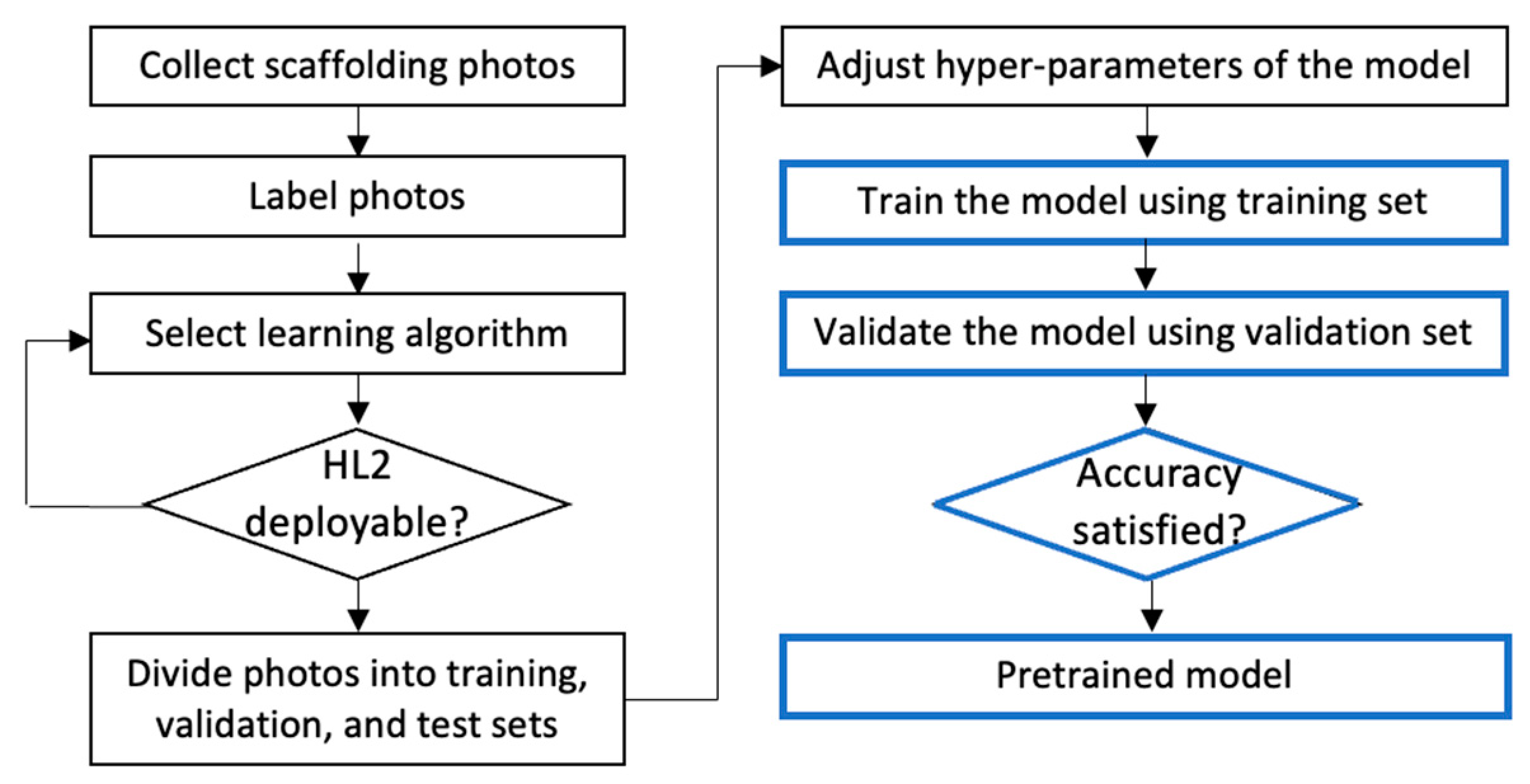
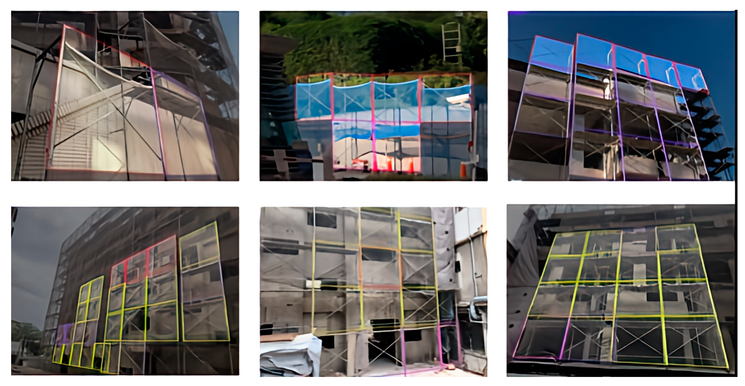
We used a deep machine learning model to automatically recognize assembly deficiencies in scaffoldings. Figure 2 depicts the process of establishing a pretrained model for recognizing deficiencies in scaffolding assemblies. The boxes on the left represent the process of preparing the training data and selecting a suitable deep learning algorithm, including collecting photos of both qualified and unqualified scaffolds, labeling scaffolding frames accordingly, developing a machine learning model, and testing the feasibility of deploying the developed algorithm on the HL2 platform. After the algorithm was developed, a machine learning model was built using Python, and the collected photos were randomly divided into training, validation, and test sets. Totals of 4240 and 530 images were used to train and validate the deep learning model, respectively. Figure 3 shows some labeling examples on the images.
The training process of deep learning includes setting up the deep learning model with initial hyperparameters, model training, and model validation. The training process may require iterations with different hyperparameters until satisfactory accuracies are obtained.
In our study, we constructed a vision recognition model using the Roboflow platform [29]. This involved preprocessing the collected images through transformations and expansions, labeling the images, creating the recognition model, and subsequently training and deploying the model. Roboflow is a freely accessible, open-source platform specifically designed to support developers in constructing, training, deploying, and sharing computer vision models. It provides an array of tools for tasks such as transforming and enhancing image data, labeling and annotating data, and training models based on the provided architectures and the developers’ own datasets. Moreover, developers can integrate computer vision capabilities into their applications by leveraging Roboflow’s API, thus automating the processing of image data and the execution of predictions.
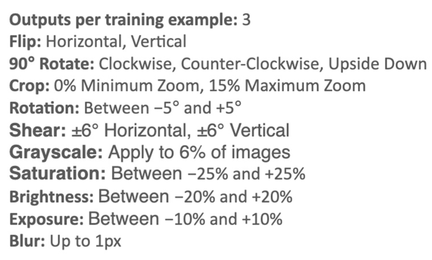
We employed Roboflow to undertake the transformation and expansion of the collected image data. The concept behind expanding the image datasets involves randomly generating diverse images based on the original images while controlling certain parameters. This approach allows for the acquisition of a larger and more diverse image dataset for training the model. Figure 4 illustrates the parameters utilized for expanding the images. Specifically, we instructed Roboflow to generate three additional images for each original image. These additional images were produced by applying horizontal or vertical flips, employing various rotation methods, and introducing degrees of cropping and shearing. To simulate different shooting conditions, encompassing scenarios with both good and poor lighting conditions, we modified the default deviation values for exposure, brightness, and saturation to 10%, 20%, and 25%, respectively. It is important to note that appropriate deviation values are those capable of generating images resembling various lighting conditions while retaining the visibility of scaffolding deficiencies recognizable by the human eye.
We considered the R-CNN [30] family of learning models, including Faster R-CNN [31] and Mask R-CNN [32], as well as YOLO for the recognition module. Among the R-CNN variants, we opted for Mask R-CNN due to its ability to provide recognition results near pixel-level boundaries instead of bounding boxes. This is particularly advantageous when video shooting is not at right angles to the building facade, as identified bounding boxes may overlap, complicating the precise localization of the problem area. Mask R-CNN, with its pixel-level boundaries, facilitates more accurate positioning of the identified issues. Consequently, we initially selected Mask R-CNN to train the developed model.
However, for reasons unknown, the Mask R-CNN trained model could not be installed on HL2. The integration of the machine learning model with HL2 is essential for the success of this research. Consequently, we chose YOLO v5 [33] instead to train the model due to its advantageous efficiency and since the trained model can be installed on HL2. The hyperparameters used include batch = 16, epoch = 300, and learning rate = 0.01. The decision to reduce the epoch from the default value of 500 to 300 was based on trial runs, which indicated that training typically plateaued between the 300th and 400th epoch, as [email protected] and [email protected] did not exhibit further improvement. The best results were consistently observed around the 250th epoch. Additional details on YOLO’s model accuracies will be presented in Section 3.

2.3.2. AR Visualization Module

Four steps were followed to use markers in the real world for integrating images of the real world with the 3D model in Unity and, subsequently, project the images to HL2.

Step 1: Marker Setup

In this study, we employed the Vuforia Engine [32] to integrate augmented reality (AR), Unity, and Microsoft’s Mixed-Reality Toolkit (MRTK), specifically for hand gesture recognition and other functionalities. For the initial stages of development, we utilized the Vuforia HoloLens 2 Sample, available on the Standard Unity Asset Store [33]. This sample provided a pre-configured Unity scene and project settings, serving as a foundational framework for the creation of a tailored application.
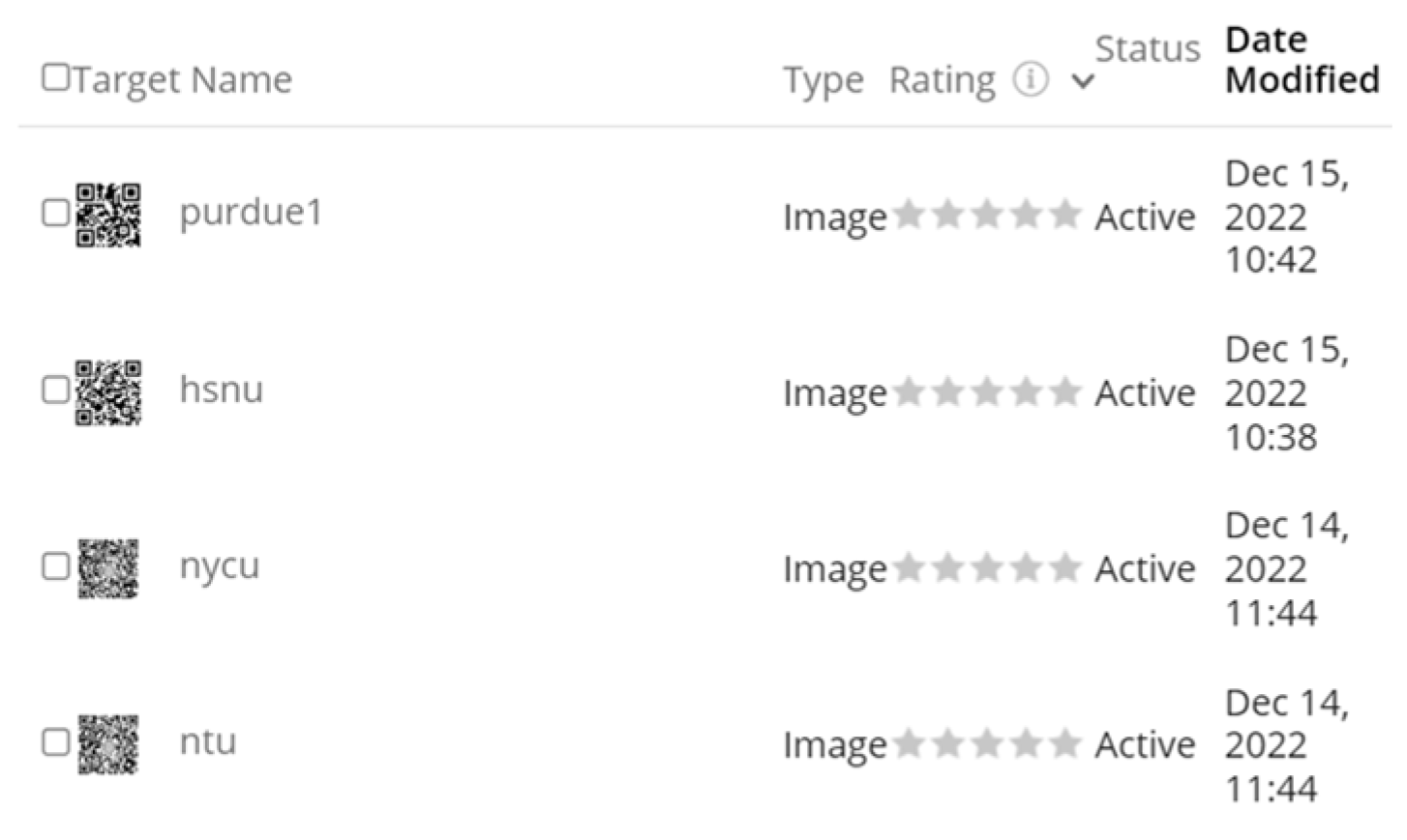
The Vuforia platform [34] offers a range of marker types with varying complexity ratings. Markers can take the form of images or objects possessing multiple discernible features. The complexity of markers influences the ease and precision of recognition, with more intricate markers enhancing recognition accuracy but requiring additional time for processing. In our approach, we opted for QR-codes based on the name of the buildings’ locations as the markers because of the reliability of QR-code detection. Figure 5 presents the recognizability ratings of the QR-codes we employed, as evaluated by Vuforia.

Step 2: Implementation and Initialization of Markers in Unity

For the execution of a Unity model on the HoloLens 2 (HL2), it is imperative to have both Unity software v.2022.2.15 [35] and the Vuforia HoloLens 2 Sample installed on the server computer. Additionally, various Mixed-Reality Toolkit (MRTK) packages, including MRTK Foundation, MRTK Extension, and the Mixed-Reality OpenXR Plugin, must be imported into Unity. Detailed information on these procedures can be found in the tutorial provided by Microsoft’s official site [36].
The implementation and initialization of markers in Unity involve the following sub-steps:
  • Navigate to the Universal Windows Platform setup page by selecting Build Settings/Platform/Universal Windows Platform.
  • Configure initialization parameters by choosing Project Settings/XR Plug-in Management/Windows and activate Initialize XR on Startup.
  • Specify the XR device by selecting Project Settings/XR Plug-in Management/Windows and activate OpenXR and the Microsoft HoloLens feature group.
  • Integrate the mobile control module by adding the Object Manipulator Script.
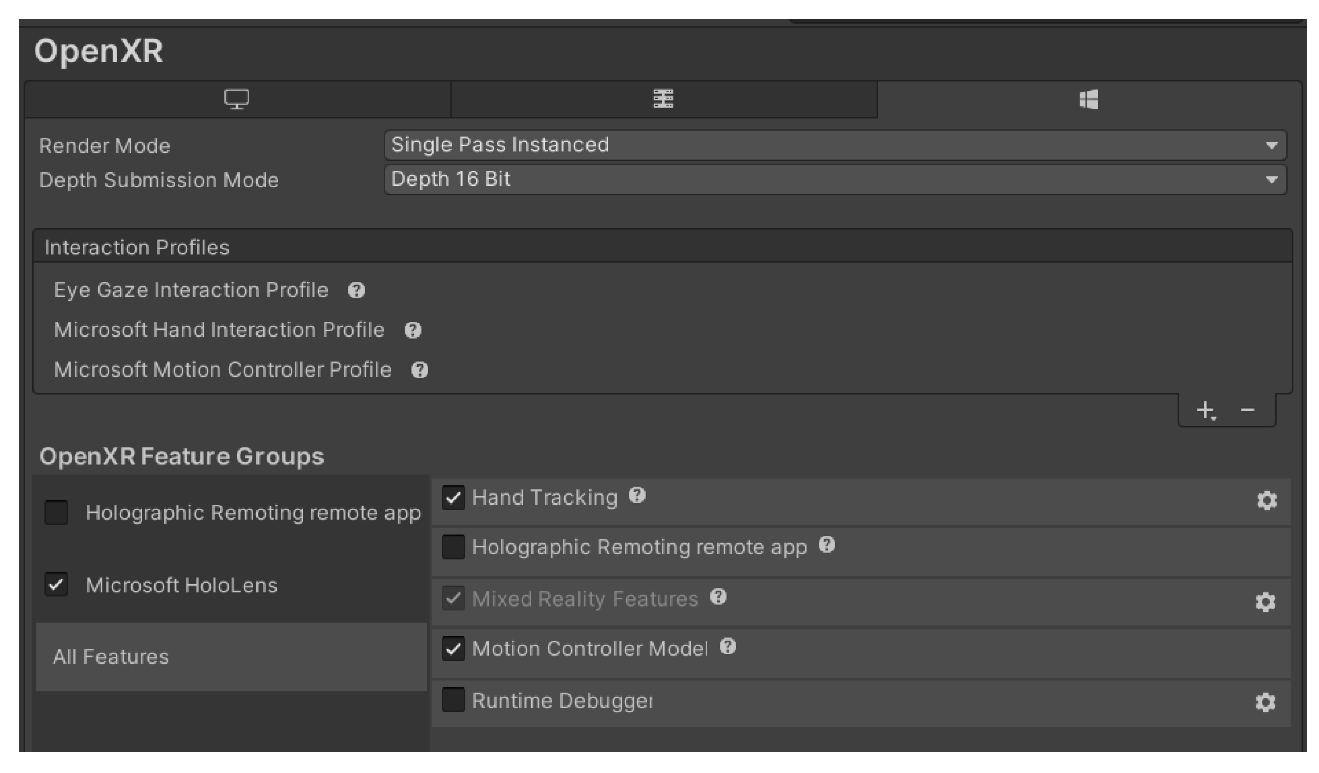
  • Incorporate the hand gesture recognition module by accessing Project Settings/OpenXR/Interaction Profiles. Choose “Eye Gaze Interaction Profile,” “Microsoft Hand Interaction Profile,” and “Microsoft Motion Controller Profile” (Figure 6).
  • Enable the hand recognition module by selecting Project Settings/OpenXR/OpenXR Feature Groups and activating Microsoft HoloLens’ “Hand Tracking” and “Motion Controller Model”.
We used different color highlights to represent different types of deficiencies in scaffolding assemblies. Half-transparent color blocks were created based on the results of the recognition module and overlayed on the Unity model.

2.3.3. HL2 Visualization Module

Pre-configuration was required to use the Unity model on the HL2 platform. To this end, the developer mode in HL2 was activated, and the exact Wi-Fi IP URL used when developing the Unity model in Microsoft Visual Studio was entered [37]. Moreover, at the construction site, QR-code markers were placed in accordance with the predetermined marker setup in the Unity model. By using these markers and the screen captured from the real world, the Unity model was re-positioned and re-oriented.

3. Results

Among the three main modules, i.e., deficiency recognition, AR visualization, and HL2 visualization modules, the deep learning model of the deficiency recognition module is the one that determines the recognition accuracy of SADDS.
During the training phase, the mean average precision (mAP) of the trained model was 0.951, precision was 88.3%, recall was 90.4%, and F1 score was 0.893 after 166 epochs. Table 2 lists the precision values of the model trained using Roboflow.
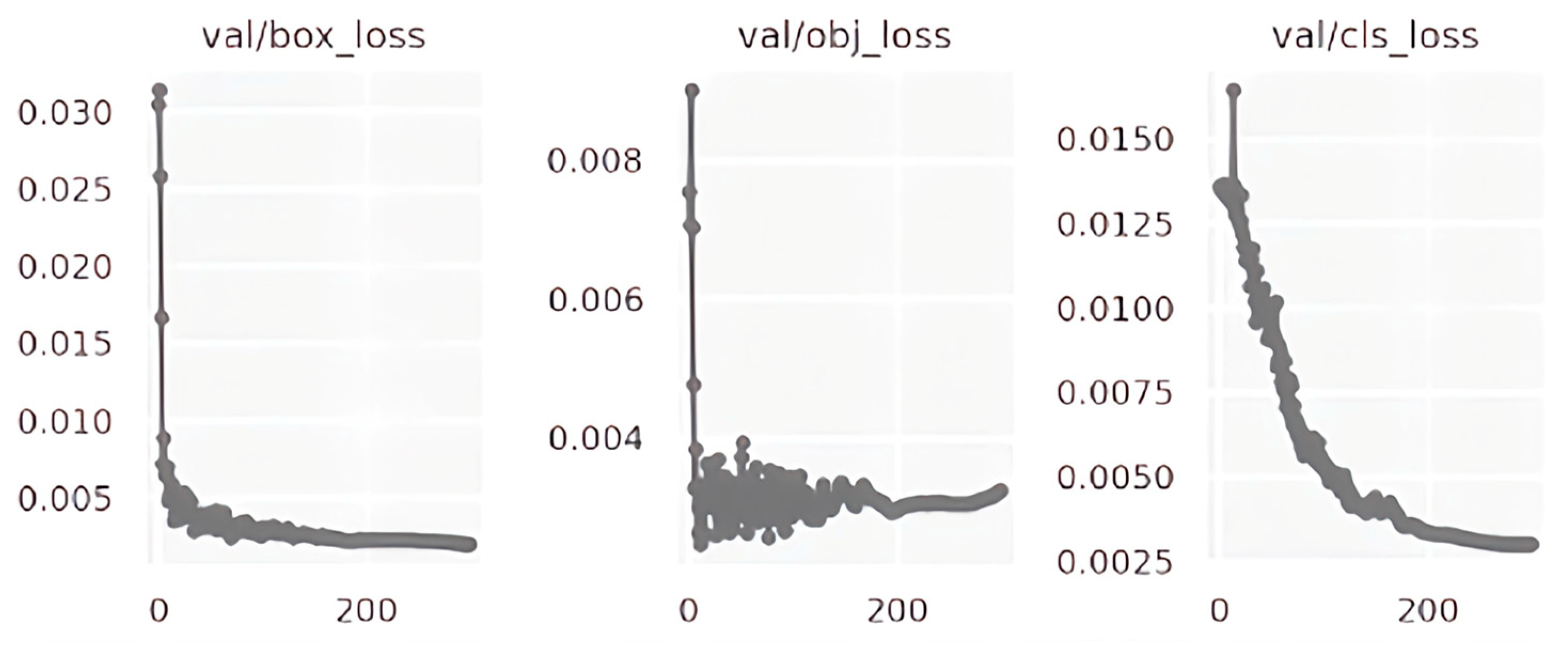
Since we did not have access to the codes of the models trained in the Roboflow platform environment, we recreated the YOLO v5 version of the model by using the pytorch package of Python, where we set batch = 16, epoch = 300, and learning_rate = 0.01. The expanded image dataset was used to train and test this model. Table 3 shows the mAP and the corresponding precisions of this self-built model for the qualified, missing cross-tie rod, missing lower-tie rod, and missing footboard classes. The test mAP was 0.89, with precision values of 0.96, 0.82, 0.90, and 0.89 for qualified, missing cross-tie rods, missing lower-tie rods, and missing footboard types of deficiencies, respectively. Table 4 and Figure 7 summarize and illustrate the losses of this model during the validation phase. Figure 8 depicts the convergence of precision, recall, and mAP in the validation phase. The precision data indicate that the results obtained using the trained model were satisfactory. The trained model was then used as the deficiency-recognition module in SADDS.
The visualization of the result of the deficiency-recognition module depends on the viewing devices. As described previously in the conceptual model of Figure 1, there are two ways of using SADDS, i.e., with or without the HL2 AR goggles, to help a user to check scaffolding frames. When a user captures images using a mobile phone or video camera, and sends the video stream to a web server, the highlights are viewed directly on the web, as shown in the left image of Figure 9.
When a user uses the HL2 AR goggles, the AR visualization module synchronizes the real world and the digital Unity model based on the QR-code markers. The center image of Figure 7 shows an example of highlights projected in the Unity model. Subsequently, the HL2 visualization module projects the highlights on HL2, as shown in the right image of Figure 7.

4. Field Test and Discussion

To field test the SADDS, we deployed it at two other construction sites, namely, 7- and 14-story concrete residential buildings, in Hshinchu City, Taiwan. One of the authors wore the HL2, walked slowly, and recorded the front and rear facades of these under-construction buildings from the exterior on the ground. The weather was cloudy and occasionally drizzly, which did not significantly affect the image quality.
Figure 10 and Figure 11 present examples of the recognition results obtained at these two test sites. Automated detection of the target deficiencies worked successfully, and most of the scaffolding frames were found to be qualified (green label), twelve had missing lower-tie rods (purple), two had missing cross-tie rods (magenta), and one had a missing footboard (red). The following lessons were learned from the field tests:
  • The camera shooting angle should be as orthogonal to the target wall face as possible. Nonetheless, the recognition module successfully recognized the deficiencies in some frames sooner or later as the wearer approached those frames. However, because the attached alert frames are always orthogonal squares, the highlights may cause humans to misread the wrong frame. This problem can be avoided so long as the camera shooting angle is orthogonal to the target wall face.
  • When shooting at an oblique angle with respect to the target wall face, far-away frames may not be recognized by the module owing to self-occlusion. This problem is understandable because even humans cannot evaluate those frames in the same situation, and those frames will be evaluated correctly once the camera moves toward them in the absence of occlusions.
  • Considering the practical use case, to enhance work efficiency and inspector’s safety, the tests were performed in front of scaffolds on the ground without actually climbing on the scaffolding boards to efficiently capture multiple frames at a glance. So long as the shooting angle is near orthogonal to the target wall face, an image with 20–50 frames did not seem to be a problem for SADDS. In this way, the use of SADDS is more efficient than inspection with the human eye. Nevertheless, in double-frame scaffold systems, most of the inner frames will not be recognized by the system owing to self-occlusion by the outer frames. Although one may stand on a scaffolding board to shoot the inner frames without occlusion, the number of frames covered in an image would be very limited, and the frames would need to be checked one by one. In such a case, direct inspection with human eyes would be more convenient.
  • Before the field test, we were concerned about the system’s ability to recognize missing cross-tie rods, which had the least precision (i.e., 0.82, compared to, for example, 0.90 for missing lower-tie rods) among the three types of target deficiencies. However, this did not seem to be a problem during the field test. A possible explanation is that in the training test, precision values were calculated per image, and each misidentification was counted. However, during actual field use, images were run as a stream, and when the HL2 wearer was moving, SADDS had many chances to successfully identify deficiencies and, eventually, alert the wearer.
  • The scaffolds at both test sites were enclosed by safety nets (e.g., anti-fall or dustproof nets), which did not affect the recognition accuracy of SADDS so long as human eyes could see through the net. Indeed, in the presence of safety nets, it was more difficult for humans to recognize unqualified assemblies from a distance than it was for SADDS.
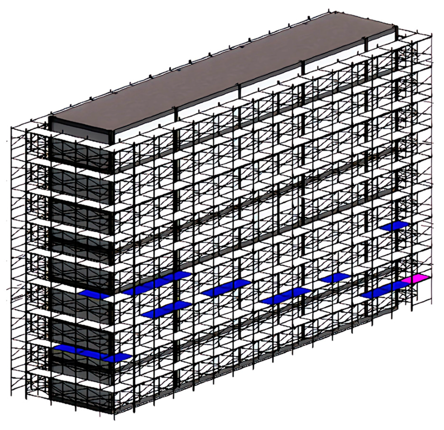
The auto-generated highlights on HL2 provide its wearer real-time warnings related to the frames of unqualified assemblies, and the wearer can suggest remedial measures right away. To record such warnings, it is best to annotate the highlight on the corresponding elements on the 3D Unity model and, if necessary, export it back to the .ifc format so that it can be read using BIM (Building Information Model)-compatible software, such as Revit v.2020. Figure 12 shows the recorded highlights of unqualified scaffolding assemblies on the corresponding elements of the Revit model.
Professionals at the test sites appreciated the real-time highlighting of unqualified scaffolding frames. This function helped inspectors to avoid missing any potential deficiencies in scaffolding assemblies even when they only glanced at such assemblies. However, they were not convinced about the need to record the highlights of unqualified frames on the 3D model. First, scaffolds are temporary structures that may be adapted frequently as the construction proceeds. Recording only a snapshot of such a dynamic temporary structure did not make sense to them. Second, A/E or construction contractors seldom implement scaffolding elements in BIM. Creating a scaffolding structure in a 3D model simply for annotating the deficiencies in the former did not seem a worthwhile endeavor to them. Note that we created the scaffolding elements manually simply for the purpose of this study.
In general, utilizing SADDS to inspect visible scaffolding deficiencies proved to be a more time-efficient process compared to relying on human inspectors. The advantages of SADDS become particularly evident when the building façade is simplified and flattened, and devoid of excessive convex or concave forms, as the system can assess multiple scaffolding frames simultaneously, surpassing the capabilities of human inspectors. This research introduces three devices for using SADDS: video cameras, mobile phones, and HL2. The speed of identifying scaffolding deficiencies is not a critical factor for any of the devices; instead, the focus lies on data preparation and processing time.
Both video cameras and mobile phones offer the benefits of convenience and affordability but lack real-time usage experience. In contrast, HL2 integrates 3D models with the real world and allows inspectors to view highlighted scaffolding deficiencies directly overlaid on real-time images of the real world. However, it comes with higher costs and requires more preparation time.
Using mobile phones is the most convenient and time-efficient option. Video cameras necessitate an additional step of transferring videos to the web server or the SADD system unless they have Wi-Fi direct uploading features. Both devices entail less data processing time compared to HL2. Considering the high video quality of modern mobile phones, we recommend using them for accessing SADDS rather than conventional video cameras.
The use of HL2 requires the most time among the three devices. For each building project, a 3D model must be available, and markers need to be setup on-site for synchronization between the 3D model and the real world on HL2. Assuming the architect or contractor has already created a 3D model for the building, HL2 provides a ‘what you see is what you get’ real-time experience and the integrated information of deficiency highlights and other location-based information from the 3D model (e.g., corresponding safety regulations). Inspectors wearing the HL2 can easily identify areas corresponding to automatically highlighted deficiencies, as the highlights directly overlay the real-world image. This is advantageous for buildings with complex facades, especially when the inspector intends to direct the superintendent to address deficiencies directly on-site. In contrast, using video cameras or mobile phones involves three steps: shooting, uploading, and playback. Inspectors can only observe highlighted deficiencies during video playback. For intricate facades, inspectors may need to make notes during video shooting to accurately pinpoint deficiency locations in the real world.
Finally, there is a multitude of deficiencies in construction scaffolding. When training deep learning models, it is essential to compile a diverse set of cases that represent various deficiency patterns. This article specifically addressed the types of deficiencies outlined in Table 1. For instance, to train the model to recognize deficiencies, such as missing cross-tie rods, lower-tie rods, or footboards, engineers can capture such types of deficiencies in the scaffolding’s front view from the side and train the model simultaneously. The simultaneous training of these three deficiency types is feasible because they share the same appropriate camera-shooting angles and could potentially coexist within the same captured image.
Conversely, identifying deficiencies in tie rods and fall protection nets necessitates engineers to position themselves either on the scaffolding or in the gap between the scaffolding and the building for optimal shooting. To spot deficiencies in the scaffolding’s base plate, engineers should focus on the scaffold’s bottom and, if necessary, capture images as close and vertically as possible toward the base plate. When identifying metal fastener deficiencies, engineers may need to concentrate on the joints between components, capturing a range of both qualified and unqualified patterns. We recommend training the model to recognize these deficiency types separately since the appropriate camera-shooting angles for each are distinct, and they rarely coexist in a single image.
In summary, the model accuracies for the qualified, missing cross-tie rod, missing lower-tie rod, and missing footboard cases were satisfactory. Subsequent field tests conducted under various lighting conditions also demonstrated satisfactory performance in practical use cases. However, these field tests highlighted certain limitations of the system. For instance, the system is unable to identify deficiencies in the inner wall of a double-walled scaffolding structure from the outside due to occlusions. Furthermore, the system’s detection of deficiencies in assemblies just marks the initial phase of automation for scaffolding inspection. Numerous visually identifiable unqualified scenarios, such as deformed frames and metal fasteners, have not been addressed in this study. These scenarios necessitate consideration in future research. Additionally, identifying these scenarios may necessitate close-distance video shooting of scaffolding frames, which raises efficiency concerns. The recognition speed of SADDS surpasses that of humans only when a single video frame encompasses multiple scaffolding frames. Consequently, there seems to be a limited benefit for an experienced inspector to utilize SADD for deficiencies that require close-distance inspection. Nevertheless, SADD may prove valuable for novice inspectors, assisting them in detecting deficiencies that might otherwise go unnoticed.
Future research will focus on enhancing recognition abilities and exploring related issues to address these concerns. Based on field experiences, we propose three avenues for future research to explore the feasibility of conquering partial obstruction, subjective quality, and measurement inspection problems.
First, there is a need to further explore identifying missing components in scaffolding, particularly in scenarios with partial obstructions, such as deficiencies within the inner wall of a double-walled scaffolding structure. Challenges arise when safety nets envelop the scaffolding structure due to constraints on feasible camera angles and increased obstruction. In cases where scaffolding assembly is completed without safety nets, the task becomes more feasible, benefiting from reduced obstruction. It is also essential to investigate the economic implications of this research direction. For instance, if the automatic identification of deficiencies requires a close-distance, frame-by-frame, or even rod-by-rod approach—such as in the identification of missing metal fasteners or connecting bolts of rods—the time saved may not justify the economic investment. In such instances, the model may transform into a quality assurance tool rather than a cost-effective solution.
The second research direction involves addressing visual deficiencies associated with subjective quality issues, such as deformed frames and rod erosion, which are discernible through visual inspection. However, the challenge lies in the subjective judgment required from inspectors to determine the urgency of remedying identified deficiencies, with experienced and novice inspectors potentially holding differing opinions. In pursuing this research direction, it is imperative to consider the selection, transformation, or reduction of feature dimensions in training images, as well as the choice of an appropriate machine learning model to enhance model accuracy. The complexity of images may necessitate a sufficient number of training datasets. In machine learning, the concept of Kolmogorov complexity, denoting the length of the shortest computer program producing the image as output [38], becomes relevant. For instance, Bolón-Canedo and Remeseiro [39] demonstrated in their experiments that model accuracy and training time could be enhanced through feature selection and reduction. Similarly, in the development of an economical and fully automated model for measuring surface wettability under non-standard conditions (e.g., nonuniform lighting and improper contrasting background color), Kabir and Garg [40] also achieved successful improvements in model accuracy and training convergence time by dimensionally reducing natural images through binarization.
The final research direction involves the development of a learning model capable of identifying scaffolding deficiencies that require measurements, such as those outlined in Articles 5 and 9 discussed in the Introduction Section. Pursuing such a research direction becomes viable only when the image-based model can recognize scaffolding components and accurately determine geometric distances among them. While the exploration of image-based learning for absolute geometric distance is still emerging, some researchers have demonstrated promising outcomes. For instance, An and Kang [41] introduced a method for inspecting the spacings of rebar binding. They utilized a laser rangefinder to measure the distance between the camera and the rebar. Subsequently, their method detected corner points of rebar binding using an enhanced Harris corner detection algorithm and estimated the distance based on the measured laser distance and pixel values. The ensuing experiment, conducted with 50 groups of rebar binding against a high-contrast wall in a laboratory, yielded satisfactory results for the first-layered bar during the daytime. However, the error rate for the two reinforcement layers increased to 23% at night. In a recent development, Xi et al. [42] proposed a method addressing improper spacing of rebar spacers. This approach employed Faster R-CNN deep learning and computational geometry to locate and classify rebar spacers, automatically identifying those with improper spacings. Human pose estimation through cascaded-pyramid-network-based deep learning was also employed to detect the three key points necessary for accurate spacing calculations.

5. Conclusions

Scaffolds are important as temporary structures that support construction processes. Accidents at construction sites are often related to scaffolds, such as insufficient support owing to deviations from the construction design, insecure rod connections, or absence of cross-bracing, which lead to uneven loading and collapse, thus resulting in casualties. Herein, we proposed a deep-learning-based, AR-enabled system called SADDS to help field inspectors identify deficiencies in scaffolding assemblies. An inspector may employ a video camera, or mobile phone, or wear AR goggles (e.g., HL2) when using SADDS for automated detection of deficiencies in scaffolding assemblies. The test mAP during training was 0.89, and the precision values for the qualified, missing cross-tie rod, missing lower-tie rod, and missing footboard cases were 0.96, 0.82, 0.90, and 0.89, respectively. The subsequent field tests conducted at two construction sites yielded satisfactory performance in practical use cases. Nevertheless, the field tests also revealed certain limitations of the system. Building upon these findings, we propose three avenues for future research, namely, identifying deficiencies with partial obstruction, subjective quality, and measurement inspection problems. We anticipate the development of additional recognition abilities and the exploration of related issues in our forthcoming research endeavors.

Author Contributions

Conceptualization, R.-J.D.; Methodology, C.-Y.C.; Software, C.-Y.C.; Validation, C.-Y.C.; Formal analysis, R.-J.D.; Investigation, C.-Y.C.; Resources, R.-J.D. and C.-W.C.; Data curation, C.-Y.C.; Writing—original draft, R.-J.D. and C.-W.C.; Writing—review & editing, R.-J.D.; Supervision, R.-J.D.; Project administration, R.-J.D.; Funding acquisition, R.-J.D. and C.-W.C.. All authors have read and agreed to the published version of the manuscript.

Funding

This research was funded by the National Science and Technology Council, Taiwan, grant numbers 108-2221-E-009-018-MY3, 112-2918-I-A49-004, and 111-2221-E-A49-040-MY3.

Data Availability Statement

The image data presented in this study are not publicly accessible due to privacy concerns related to the collaborative companies involved, and are available on request from the corresponding author. The trained model presented in this study is openly available on the Roboflow platform and can be accessed at https://universe.roboflow.com/site/1213-zvjqz.

Conflicts of Interest

The authors declare no conflicts of interest.

References

  1. Li, S.; Gu, X.; Xu, X.; Xu, D.; Zhang, T.; Liu, Z.; Dong, Q. Detection of concealed cracks from ground penetrating radar images based on deep learning algorithm. Constr. Build. Mater. 2021, 273, 121949. [Google Scholar] [CrossRef]
  2. Fang, W.; Ding, L.; Zhong, B.; Love, P.E.; Luo, H. Automated detection of workers and heavy equipment on construction sites: A convolutional neural network approach. Adv. Eng. Inform. 2018, 37, 139–149. [Google Scholar] [CrossRef]
  3. Reja, V.K.; Varghese, K.; Ha, Q.P. Computer vision-based construction progress monitoring. Autom. Constr. 2022, 138, 104245. [Google Scholar] [CrossRef]
  4. Shanti, M.Z.; Cho, C.S.; Byon, Y.J.; Yeun, C.Y. A novel implementation of an AI-based smart construction safety inspection protocol in the UAE. IEEE Access 2021, 9, 166603–166616. [Google Scholar] [CrossRef]
  5. Park, S.E.; Eem, S.H.; Jeon, H. Concrete crack detection and quantification using deep learning and structured light. Constr. Build. Mater. 2020, 252, 119096. [Google Scholar] [CrossRef]
  6. Alavi, A.H.; Buttlar, W.G. An overview of smartphone technology for citizen-centered, real-time and scalable civil infrastructure monitoring. Future Gener. Comput. Syst. 2019, 93, 651–672. [Google Scholar] [CrossRef]
  7. Sarmadi, H.; Entezami, A.; Yuen, K.V.; Behkamal, B. Review on smartphone sensing technology for structural health monitoring. Measurement 2023, 223, 113716. [Google Scholar] [CrossRef]
  8. Yu, L.; Lubineau, G. A smartphone camera and built-in gyroscope based application for non-contact yet accurate off-axis structural displacement measurements. Measurement 2021, 167, 108449. [Google Scholar] [CrossRef]
  9. Nazar, A.M.; Jiao, P.; Zhang, Q.; Egbe, K.J.I.; Alavi, A.H. A new structural health monitoring approach based on smartphone measurements of magnetic field intensity. IEEE Instrum. Meas. Mag. 2021, 24, 49–58. [Google Scholar] [CrossRef]
  10. Han, R.; Zhao, X.; Yu, Y.; Guan, Q.; Hu, W.; Li, M. A cyber-physical system for girder hoisting monitoring based on smartphones. Sensors 2016, 16, 1048. [Google Scholar] [CrossRef]
  11. Zhao, X.; Han, R.; Yu, Y.; Li, M. Research on quick seismic damage investigation using smartphone. In Proceedings of the SPIE 9804, Nondestructive Characterization and Monitoring of Advanced Materials, Aerospace, and Civil Infrastructure, Las Vegas, NV, USA, 21–24 March 2016; p. 980421. [Google Scholar]
  12. Microsoft. HoloLens 2 Release Notes. 2023. Available online: https://learn.microsoft.com/en-us/hololens/hololens-release-notes#about-hololens-releases (accessed on 10 November 2023).
  13. Leite, F.; Cho, Y.; Behzadan, A.H.; Lee, S.H.; Choe, S.; Fang, Y.; Akhavian, R.; Hwang, S. Visualization, information modeling, and simulation: Grand challenges in the construction industry. J. Comput. Civ. Eng. 2016, 30, 04016035. [Google Scholar] [CrossRef]
  14. Park, S.; Bokijonov, S.; Choi, Y. Review of Microsoft HoloLens applications over the past five years. Appl. Sci. 2020, 11, 7259. [Google Scholar] [CrossRef]
  15. Pratt, P.; Ives, M.; Lawton, G.; Simmons, J.; Radev, N.; Spyropoulou, L.; Amiras, D. Through the HoloLens looking glass: Augmented reality for extremity reconstruction surgery using 3D vascular models with perforating vessels. Eur. Radiol. Exp. 2018, 2, 2. [Google Scholar] [CrossRef] [PubMed]
  16. Al-Maeeni Sara, S.H.; Kuhnhen, C.; Engel, B.; Schiller, M. Smart retrofitting of machine tools in the context of industry 4.0. Procedia CIRP 2019, 88, 369–374. [Google Scholar] [CrossRef]
  17. Hübner, P.; Clintworth, K.; Liu, Q.; Weinmann, M.; Wursthorn, S. Evaluation of HoloLens tracking and depth sensing for indoor mapping applications. Sensors 2020, 20, 1021. [Google Scholar] [CrossRef] [PubMed]
  18. Wu, M.; Dai, S.-L.; Yang, C. Mixed reality enhanced user interactive path planning for omnidirectional mobile robot. Appl. Sci. 2020, 10, 1135. [Google Scholar] [CrossRef]
  19. Mourtzis, D.; Siatras, V.; Zogopoulos, V. Augmented reality visualization of production scheduling and monitoring. Procedia CIRP 2020, 88, 151–156. [Google Scholar] [CrossRef]
  20. Moezzi, R.; Krcmarik, D.; Hlava, J.; Cýrus, J. Hybrid SLAM modeling of autonomous robot with augmented reality device. Mater. Today Proc. 2020, 32, 103–107. [Google Scholar] [CrossRef]
  21. Karaaslan, E.; Bagci, U.; Catbas, F.N. Artificial intelligence assisted infrastructure assessment using mixed reality systems. Transp. Res. Rec. 2019, 2673, 413–424. [Google Scholar] [CrossRef]
  22. Sanni-Anibire, M.O.; Salami, B.A.; Muili, N. A framework for the safe use of bamboo scaffolding in the Nigerian construction industry. Saf. Sci. 2022, 151, 105725. [Google Scholar] [CrossRef]
  23. Abdel-Jaber, M.; Beale, R.G.; Godley, M.H.R. A theoretical and experimental investigation of pallet rack structures under sway. J. Constr. Steel Res. 2006, 62, 68–80. [Google Scholar] [CrossRef]
  24. Abdel-Jaber, M.; Abdel-Jaber, M.S.; Beale, R.G. An Experimental Study into the Behaviour of Tube and Fitting Scaffold Structures under Cyclic Side and Vertical Loads. Metals 2022, 12, 40. [Google Scholar] [CrossRef]
  25. Baek, C.W.; Lee, D.Y.; Park, C.S. Blockchain based Framework for Verifying the Adequacy of Scaffolding Installation. In Proceedings of the 37th ISARC (International Symposium on Automation and Robotics in Construction), Kitakyushu, Japan, 27–28 October 2020; IAARC Publications. 2020; Volume 37, pp. 425–432. Available online: https://www.researchgate.net/profile/Chanwoo-Baek-2/publication/346222919_Blockchain_based_Framework_for_Verifying_the_Adequacy_of_Scaffolding_Installation/links/5fbf641892851c933f5d3492/Blockchain-based-Framework-for-Verifying-the-Adequacy-of-Scaffolding-Installation.pdf (accessed on 24 December 2023).
  26. Sakhakarmi, S.; Park, J.W.; Cho, C. Enhanced machine learning classification accuracy for scaffolding safety using increased features. J. Constr. Eng. Manag. 2019, 145, 04018133. [Google Scholar] [CrossRef]
  27. Choa, C.; Sakhakarmi, S.; Kim, K.; Park, J.W. Scaffolding Modeling for Real-time Monitoring Using a Strain Sensing Approach. In Proceedings of the 35th ISARC (International Symposium on Automation and Robotics in Construction), Berlin, Germany, 20–25 July 2018; pp. 48–55. [Google Scholar] [CrossRef]
  28. Ministry of Labor of Taiwan. Safety Regulations for Inspecting Construction Scaffolding. 2018. Available online: https://laws.mol.gov.tw/FLAW/FLAWDAT01.aspx?id=FL083843 (accessed on 1 November 2023). (In Chinese)
  29. Roboflow, Inc. Roboflow Official Site. 2023. Available online: https://roboflow.com/ (accessed on 1 December 2023).
  30. Uijlings, J.; van de Sande, K.; Gevers, T.; Smeulders, A. Selective search for object recognition. Int. J. Comput. Vis. 2013, 104, 154–171. [Google Scholar] [CrossRef]
  31. Ren, S.; He, K.; Girshick, R.B.; Sun, J. Faster R-CNN: Towards real-time object detection with region proposal networks. Adv. Neural Inf. Process. Syst. 2015, 28, 91–99. [Google Scholar] [CrossRef] [PubMed]
  32. He, K.; Gkioxari, G.; Dollár, P.; Girshick, R. Mask R-CNN. In Proceedings of the 2017 IEEE International Conference on Computer Vision (ICCV), Venice, Italy, 22–29 October 2017; pp. 2980–2988. [Google Scholar] [CrossRef]
  33. Jocher, G.; Stoken, A.; Borovec, J.; NanoCode012; ChristopherSTAN; Liu, C.; Laughing; Tkianai; YxNONG; Hogan, A.; et al. Ultralytics/yolov5: V4.0—Nn.SiLU() Activations, Weights & Biases Logging, PyTorch Hub Integration. 2021. Available online: https://zenodo.org/records/4418161 (accessed on 24 December 2023).
  34. PTC. Vuforia Engine Developer’s Portal. 2023. Available online: https://developer.vuforia.com/ (accessed on 20 May 2023).
  35. Unity. Vuforia Hololens 2 Sample. 2023. Available online: https://assetstore.unity.com/packages/templates/packs/vuforia-hololens-2-sample-101553 (accessed on 1 December 2023).
  36. Microsoft Inc. Introduction to the Mixed Reality Toolkit-Set up Your Project and Use Hand Interaction. HoloLens 2 Fundamentals: Develop Mixed Reality Applications. 2023. Available online: https://learn.microsoft.com/en-us/training/modules/learn-mrtk-tutorials/ (accessed on 1 December 2023).
  37. Microsoft Inc. GitHub Copilot and Visual Studio 2022. 2023. Available online: https://visualstudio.microsoft.com/zh-hant/ (accessed on 1 December 2023).
  38. Li, M.; Vitányi, P. An Introduction to Kolmogorov Complexity and Its Applications; Springer: Berlin/Heidelberg, Germany, 2008. [Google Scholar]
  39. Bolón-Canedo, V.; Remeseiro, B. Feature selection in image analysis: A survey. Artif. Intell. Rev. 2020, 53, 2905–2931. [Google Scholar] [CrossRef]
  40. Kabir, H.; Garg, N. Machine learning enabled orthogonal camera goniometry for accurate and robust contact angle measurements. Sci. Rep. 2023, 13, 1497. [Google Scholar] [CrossRef] [PubMed]
  41. An, M.; Kang, D.S. The distance measurement based on corner detection for rebar spacing in engineering images. J. Supercomput. 2022, 78, 12380–12393. [Google Scholar] [CrossRef]
  42. Xi, J.; Gao, L.; Zheng, J.; Wang, D.; Tu, C.; Jiang, J.; Miao, Y.; Zhong, J. Automatic spacing inspection of rebar spacers on reinforcement skeletons using vision-based deep learning and computational geometry. J. Build. Eng. 2023, 79, 107775. [Google Scholar] [CrossRef]
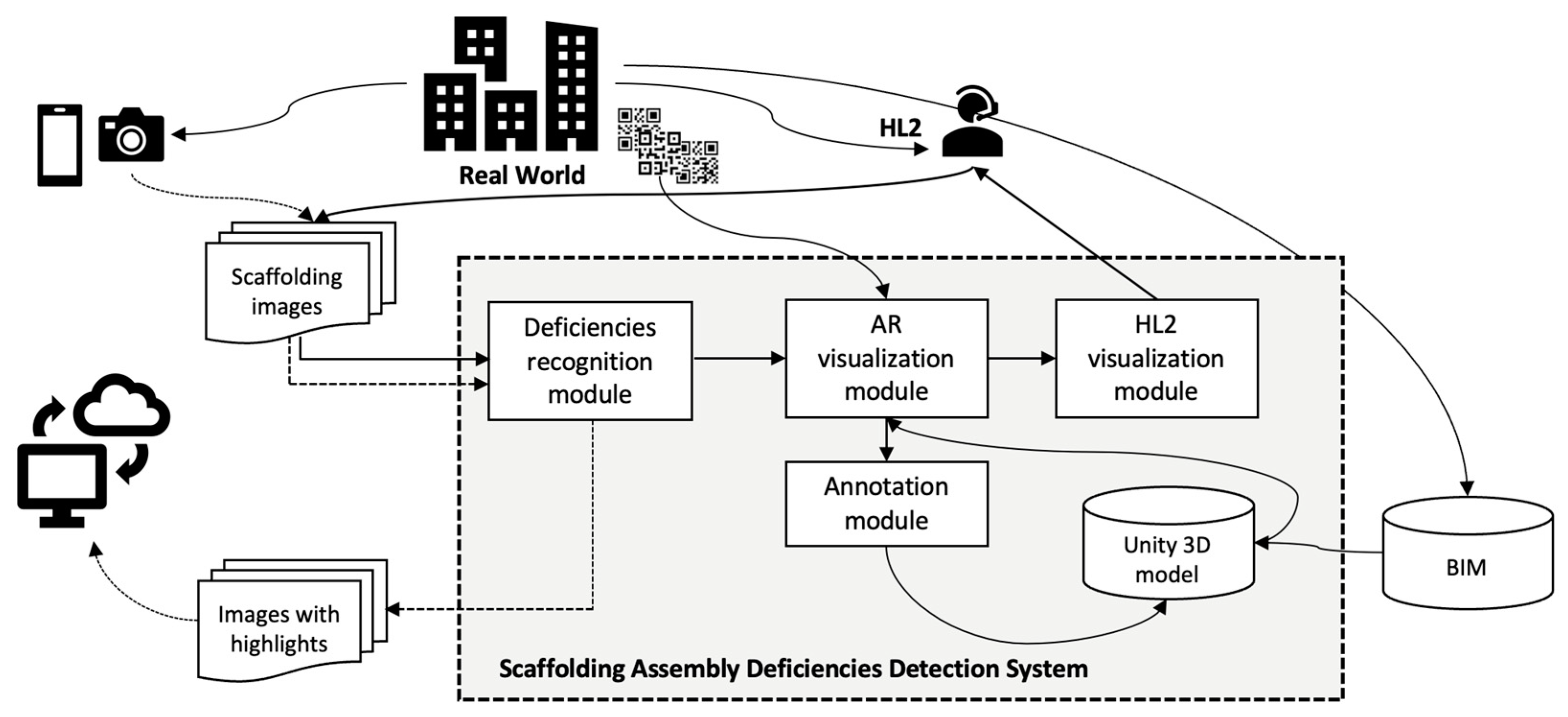
Figure 1. Conceptual model of the scaffolding assembly deficiencies detection system.
Buildings 14 00385 g001
Figure 2. Preparation (black boxes) and pretraining process (blue boxes) of the deep learning model in the deficiency-recognition module.
Buildings 14 00385 g002
Figure 3. Examples of frame labeling in photos. (yellow: qualified; magenta: missing cross-tie rod; purple: missing lower-tie rod; red: missing footboard).
Buildings 14 00385 g003
Figure 4. Parameters used for expanding the image dataset.
Buildings 14 00385 g004
Figure 5. Ratings of the markers used by Vuforia.
Buildings 14 00385 g005
Figure 6. Adding the hand gesture recognition module in Unity.
Buildings 14 00385 g006
Figure 7. Validation losses.
Buildings 14 00385 g007
Figure 8. Precision, recall, and mAP in the validation phase.
Buildings 14 00385 g008
Figure 9. Comparison of color highlights by YOLO (left) (yellow: qualified; purple: missing lower-tie rod), Unity model (center), and HL2 (right) (green: qualified; blue: missing cross-tie rod).
Buildings 14 00385 g009
Figure 10. Examples of images obtained in a field test involving a 7-story building. (yellow: qualified; magenta: missing cross-tie rod; purple: missing lower-tie rod; red: missing footboard).
Buildings 14 00385 g010
Figure 11. Examples of images obtained in a field test involving a 14-story building. (yellow: qualified; red: missing footboard).
Buildings 14 00385 g011
Figure 12. Recorded highlights on the corresponding elements in BIM. (magenta: missing cross-tie rod; blue: missing lower-tie rod).
Buildings 14 00385 g012
Table 1. Comparison between a qualified scaffold assembly and those with deficiencies.
QualifiedMissing Cross-Tie RodMissing Lower-Tie RodMissing Footboard
Buildings 14 00385 i001Buildings 14 00385 i002Buildings 14 00385 i003Buildings 14 00385 i004
Buildings 14 00385 i005Buildings 14 00385 i006Buildings 14 00385 i007Buildings 14 00385 i008
0: yellow (763)1: magenta (245)2: purple (575)3: red (643)
Table 2. Mean average precision values of the model trained using Roboflow.
mAPQualifiedMissing Cross-Tie RodMissing Lower-Tie RodMissing Footboard
Validation0.940.970.960.9370.93
Test0.880.950.800.900.88
Table 3. Mean average precision values of the self-built trained model.
mAPQualifiedMissing Cross-Tie RodMissing Lower-Tie RodMissing Footboard
Validation0.960.980.9790.900.96
Test0.890.960.820.900.89
Table 4. Losses of the self-built trained model.
Box LossObject LossClass Loss
Validation0.0020 0.0032 0.0030
Test0.00210.00410.0037
Disclaimer/Publisher’s Note: The statements, opinions and data contained in all publications are solely those of the individual author(s) and contributor(s) and not of MDPI and/or the editor(s). MDPI and/or the editor(s) disclaim responsibility for any injury to people or property resulting from any ideas, methods, instructions or products referred to in the content.