
Study on the Soil–Pile Interaction of Slender Piles in Multi-Layered Soil by the Variational Analysis Method


Abstract
1. Introduction
2. Calculation Principle of Variational Method
2.1. Pile–Soil Interaction Model
- The pile is modeled as the Euler–Bernoulli Beam.
- The soil within each soil layer is a uniform, isotropic, ideal elastic material.
- The pile and the soil maintain contact throughout the deformation process.
2.2. Calculation of Horizontal Displacement of Pile
2.3. Calculation of Transfer Function
2.4. Iterative Solution Process
- The expression for the pile-tip boundary condition is improved, making it more consistent with the characteristics of long slender piles.
- The iterative calculation process is simplified, enhancing the computational efficiency.
2.5. Pile–Soil Interaction Analysis
3. Example Verification
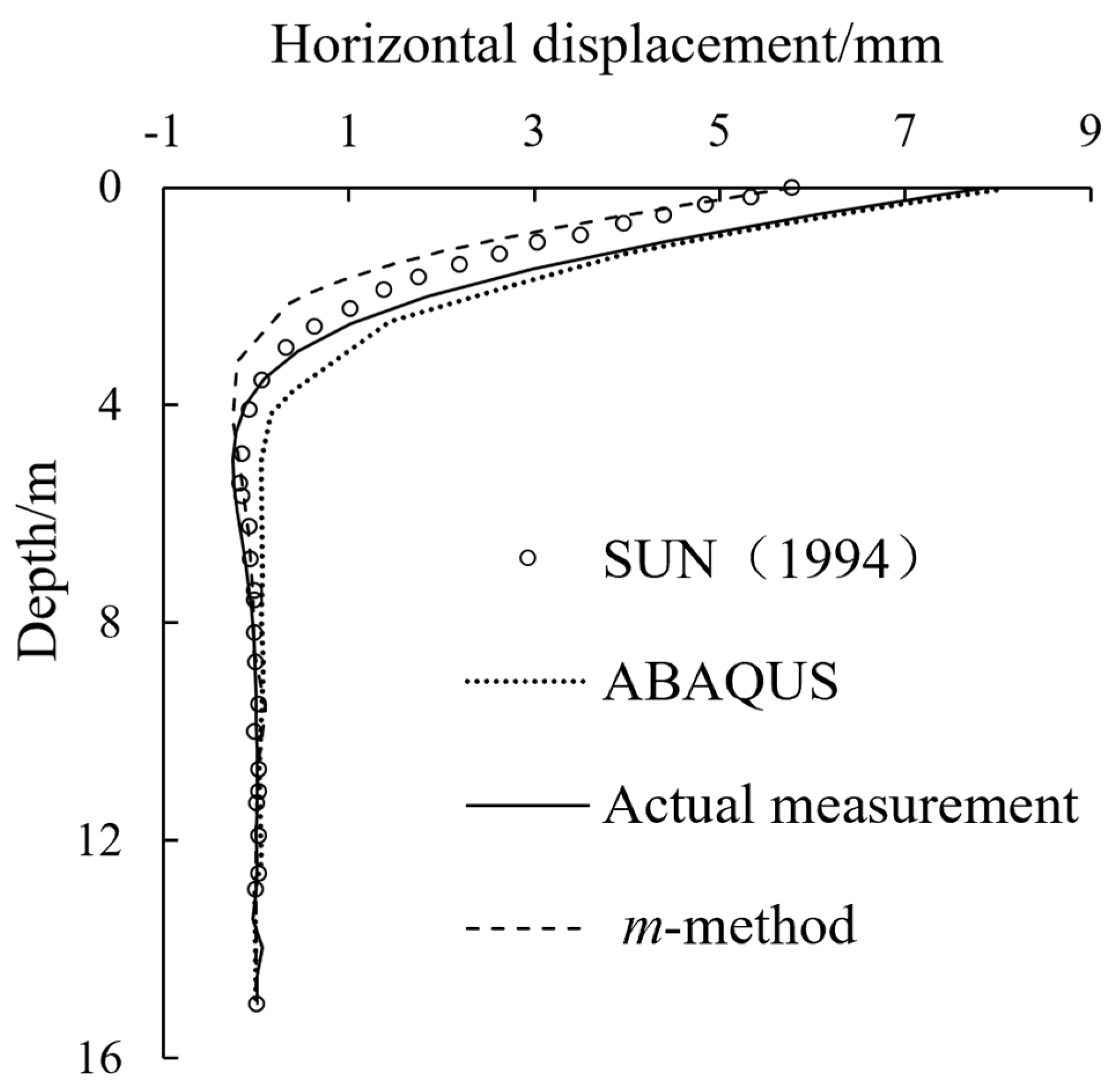
3.1. Example 1
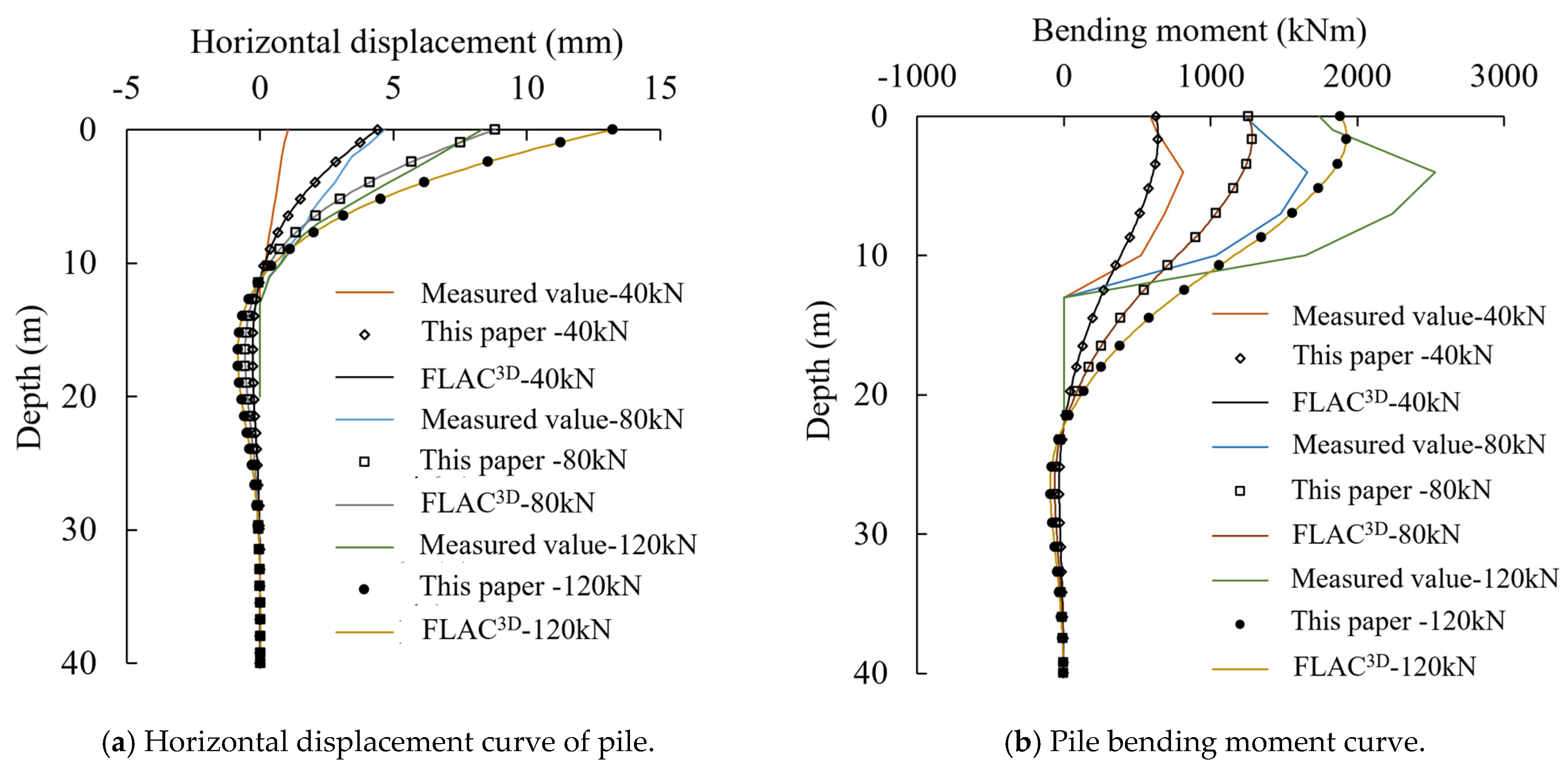
3.2. Example 2
4. Engineering Applications
4.1. Relevant Parameters
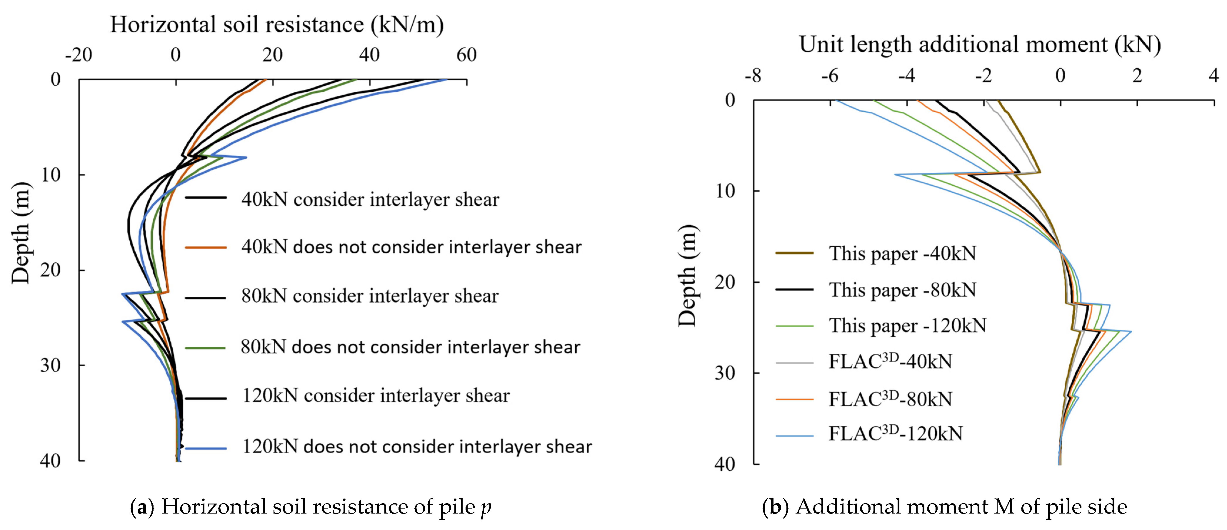
4.2. Pile–Soil Interaction
- (1)
- There is a time difference between geotechnical testing and the start of pile testing. Due to the characteristics of the local marine environment, the scouring effect is significant, which may result in certain differences between the actual surface soil layer and the geological exploration soil layer.
- (2)
- There is a problem with determining the value of the elastic modulus, Es. Since Es is mainly obtained based on laboratory geotechnical tests and local experience, there may be some differences compared to the actual situation.
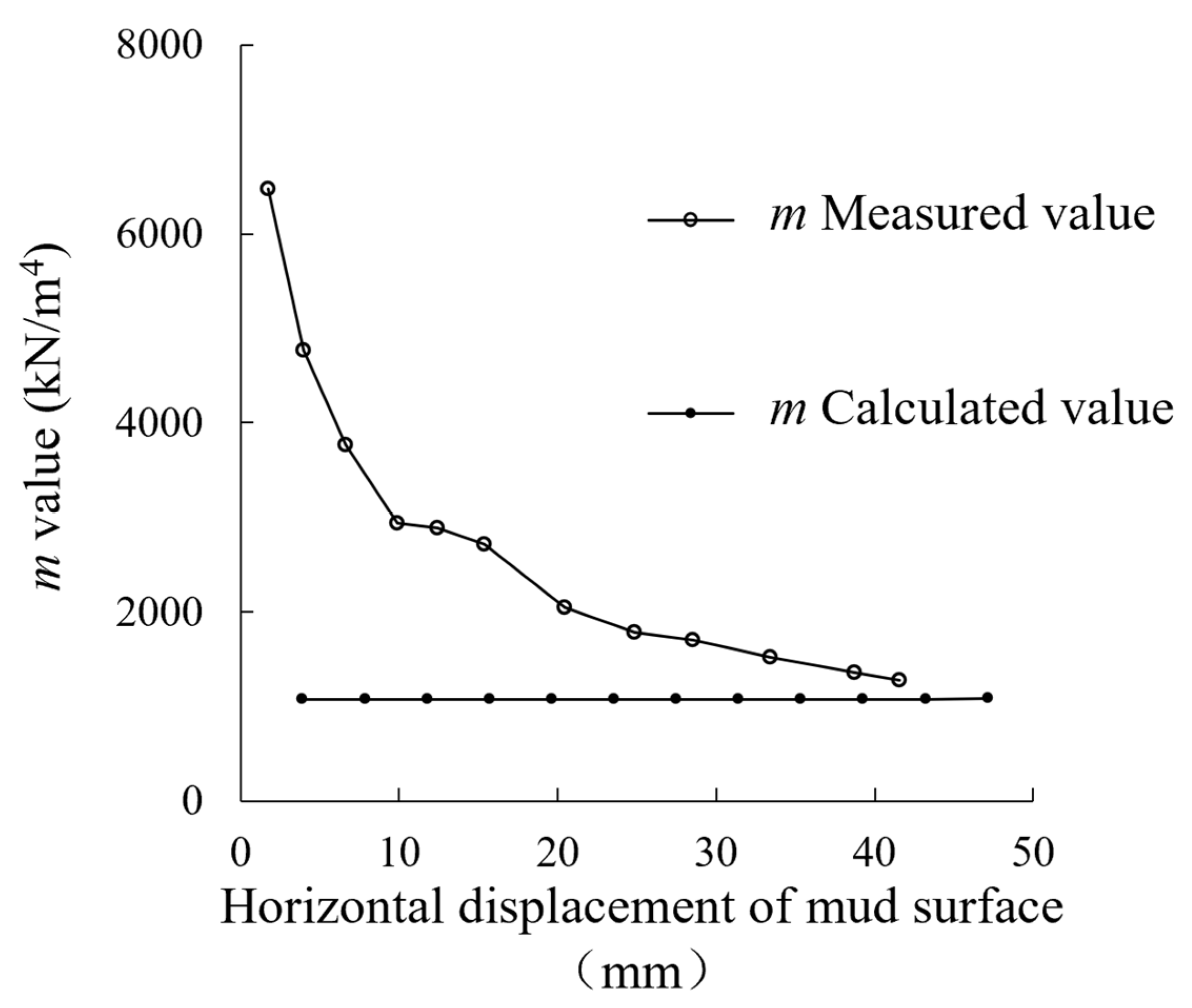
4.3. Estimation of m Value
5. Conclusions
- Horizontal soil resistance at the pile side is the dominant factor in the total soil resistance, the influence of shear interaction between soil layers on the horizontal soil resistance is about 9~20%, and the calculation of horizontal soil resistance should fully consider the impact of shear interaction between soil layers.
- The additional moment on the pile side is beneficial in terms of improving the horizontal bearing capacity of the pile body, but the enhancement effect is negligible.
- The obtained m-value from the method presented in this paper is the lower bound of the measured results.
- The method in this paper can accurately predict the responses of long slender piles under horizontal load and the distribution of soil resistance around the pile. Compared to the numerical analysis method, it has a faster calculation speed and accurate results. However, the constitutive model of the soil in this paper cannot reflect the influence of the loading path and plastic evolution on the pile–soil interaction, and it cannot simulate the detachment effect at the pile–soil interface. These aspects will represent research directions in the future.
Author Contributions
Funding
Data Availability Statement
Conflicts of Interest
References
- Zhang, F.; Dai, G.; Li, X.; Xu, F.; Gong, W. Numerical solution for the laterally loaded rigid piles considering resisting force and moment under combined loadings. Ocean Eng. 2024, 292, 116225. [Google Scholar] [CrossRef]
- Bai, X.Y.; Zhang, Y.J.; Yan, N.; Liu, J.W.; Zhang, Y.M. Experimental investigation on bearing capacity of rock-socketed bored piles in silty clay stratum in beach areas. Appl. Ocean Res. 2025, 154, 104336. [Google Scholar] [CrossRef]
- Qin, W.; Dai, G.; Zhao, X.; Shu, G.; Gong, W. Experimental Investigation of CFFP-Soil Interaction in Sand under Cyclic Lateral Loading. Geotech. Test. J. 2019, 42, 1055–1074. [Google Scholar] [CrossRef]
- Li, X.; Dai, G.; Zhu, M.; Wang, L.; Liu, H. A Simplified Method for Estimating the Initial Stiffness of Monopile—Soil Interaction Under Lateral Loads in Offshore Wind Turbine Systems. China Ocean Eng. 2023, 37, 165–174. [Google Scholar] [CrossRef]
- Ministry of Transport of the People’s Republic of China. Code for Pile Foundations of Port Engineering (JTS 167-4-2012); People’s Communications Press: Beijing, China, 2012. [Google Scholar]
- Ministry of Housing and Urban-Rural Development of the People’s Republic of China. Technical Specification for Testing of Building Pile Foundations (JGJ 106-2014); China Architecture & Building Press: Beijing, China, 2014. [Google Scholar]
- Qin, W.; Li, X.; Dai, G.; Hu, P. Analytical Penetration Solutions of Large-Diameter Open-Ended Piles Subjected to Hammering Loads. J. Mar. Sci. Eng. 2022, 10, 885. [Google Scholar] [CrossRef]
- Ouyang, H.; Dai, G.; Qin, W.; Zhang, C.; Zhu, W.; Gong, W. Experimental study on the mechanical behaviors and particle breakage characteristics of calcareous sand from South China Sea under repeated one-dimensional impacts. Acta Geotech. 2022, 17, 3927–3946. [Google Scholar] [CrossRef]
- OuYang, H.; Dai, G.; Qin, W.; Zhang, C.; Gong, W. Dynamic behaviors of calcareous sand under repeated one-dimensional impacts. Soil Dyn. Earthq. Eng. 2021, 150, 106891. [Google Scholar] [CrossRef]
- Qin, W.; Cai, S.; Dai, G.; Wang, D.; Chang, K. Soil Resistance during Driving of Offshore Large-Diameter Open-Ended Thin-Wall Pipe Piles Driven into Clay by Impact Hammers. Comput. Geotech. 2023, 153, 105085. [Google Scholar] [CrossRef]
- Chang, K.; Wang, D.; Hossain, M.S.; Kim, Y.H.; Qin, W. Effective stress analysis of dynamically installed anchor installation in rate-dependent clay. Ocean Eng. 2022, 266, 113183. [Google Scholar] [CrossRef]
- Sun, K. Laterally loaded piles in elastic media. J. Geotech. Eng. 1994, 120, 1324–1344. [Google Scholar] [CrossRef]
- Li, X.; Dai, G.; Yin, Q.; Yang, X.; Gong, W. A continuum-based model for a laterally loaded steel pipe pile in layered soils in offshore wind farms. Arab. J. Geosci. 2021, 14, 1605. [Google Scholar] [CrossRef]
- Li, X.; Zhu, M.; Dai, G.; Wang, L.; Liu, J. Interface Mechanical Behavior of Flexible Piles Under Lateral Loads in OWT Systems. China Ocean Eng. 2023, 37, 484–494. [Google Scholar] [CrossRef]
- Li, X.; Dai, G.; Zhu, M.; Zhu, W.; Zhang, F. Investigation of the soil deformation around laterally loaded deep foundations with large diameters. Acta Geotech. 2024, 19, 2293–2314. [Google Scholar] [CrossRef]
- Li, X.; Dai, G.; Zhang, F.; Gong, W. Energy-based analysis of laterally loaded caissons with large diameters under small-strain conditions. Int. J. Geomech. 2022, 22, 05022005. [Google Scholar] [CrossRef]
- Salgado, R.; Seo, H.; Prezzi, M.; Tehran, F.S. Variational elastic solution for axially loaded piles in multilayered soil. Int. J. Numer. Anal. Methods Geomech. 2013, 37, 423–440. [Google Scholar] [CrossRef]
- Salgado, R.; Tehrani, F.S.; Prezzi, M. Analysis of laterally loaded pile groups in multilayered elastic soil. Comput. Geotech. 2014, 62, 136–153. [Google Scholar] [CrossRef]
- Basu, D.; Salgado, R.; Prezzi, M. A new framework for analysis of laterally loaded piles. J. Geo-Eng. Sci. 2013, 1, 53–67. [Google Scholar] [CrossRef]
- Han, F.; Salgado, R.; Prezzi, M. Nonlinear analyses of laterally loaded piles—A semi-analytical approach. Comput. Geotech. 2015, 70, 116–129. [Google Scholar] [CrossRef]
- Han, F.; Prezzi, M.; Salgado, R. Energy-based solutions for nondisplacement piles subjected to lateral loads. Int. J. Geomech. 2017, 17, 04017104. [Google Scholar] [CrossRef]
- Han, F.; Salgado, R.; Prezzi, M. A semi-analytical method for analysis of laterally loaded piles in elastoplastic soil. In Proceedings of the 19th International Conference on Soil Mechanics and Geotechnical Engineering, Seoul, Republic of Korea, 17–21 September 2017; pp. 2771–2774. [Google Scholar]
- Teja, M.; Kumar, K.G. Influence of Stratified Soil System on Behavior of Laterally Loaded Pile Groups: An Experimental Study. Int. J. Geosynth. Ground Eng. 2021, 7, 18. [Google Scholar]
- Gupta, B.K.; Basu, D. Applicability of Timoshenko, Euler–Bernoulli and rigid beam theories in analysis of laterally loaded monopiles and piles. Géotechnique 2018, 68, 772–785. [Google Scholar] [CrossRef]
- Li, X.; Dai, G.; Zhu, M.; Gong, W. Application of static loading tests to steel pipe piles with large diameters in Chinese offshore wind farms. Ocean Eng. 2019, 186, 106041. [Google Scholar] [CrossRef]


| Methods | Horizontal Soil Resistance Expression | Initial Stiffness Expression | Remarks |
|---|---|---|---|
| Constant method | k is a constant. | Based on the distributed spring method, it cannot reflect the layered shear effect or the distributed moment around the pile. | |
| m-method | k = mz. m is a constant; k increases linearly with soil depth. | ||
| C-method | k = Cz0.5, m is a constant; k increases linearly with soil depth. | ||
| K-method | -- | k remains a constant below the first elastic zero point, while above this point, it decreases along a concave curve. | |
| Comprehensive stiffness method | p = K(z)w | k = mzi, m is a constant, i > 0. The shape of the distribution curve of k along z is controlled by the different values of i. | |
| Multi-parameter method | p = Kbwl | k = Kb, K = z0 + mz1/n or m(z0 + z)1/n. m and n are the deformation coefficient and exponent, b is the equivalent width of the foundation, and z0 is the equivalent depth. z0 = 0, n is a constant; when m is not a constant, it is referred to as the single-parameter method. z0 is a constant; when n is not a constant and m is also not a constant, it is referred to as the two-parameter method; when all three are not constants, it is referred to as the parameter method. | |
| The method in this paper | t and k refer to the following text. | Based on the continuum theory, it can comprehensively reflect the layered shear effect and the distributed moment around the pile. |
| Soil Layer | Layer Thickness/m | Elastic Modulus Es/MPa | Poisson’s Ratio vs |
|---|---|---|---|
| 1 | 1.5 | 20 | 0.35 |
| 2 | 2.0 | 25 | 0.30 |
| 3 | 5.0 | 40 | 0.25 |
| 4 | 32 | 80 | 0.20 |
| Soil Layer | Layer Thickness/m | Elastic Modulus Es/MPa | Poisson’s Ratio vs |
|---|---|---|---|
| 1 | 2.0 | 1.6 | 0.3 |
| 2 | 4.0 | 4.8 | 0.3 |
| 3 | 4.0 | 8.0 | 0.3 |
| 4 | 7.5 | 14.0 | 0.3 |
Disclaimer/Publisher’s Note: The statements, opinions and data contained in all publications are solely those of the individual author(s) and contributor(s) and not of MDPI and/or the editor(s). MDPI and/or the editor(s) disclaim responsibility for any injury to people or property resulting from any ideas, methods, instructions or products referred to in the content. |
© 2024 by the authors. Licensee MDPI, Basel, Switzerland. This article is an open access article distributed under the terms and conditions of the Creative Commons Attribution (CC BY) license (https://creativecommons.org/licenses/by/4.0/).
Share and Cite
Chen, T.; Xi, S.; Qian, C.; Wang, P.; Zhu, M.; Liang, Z. Study on the Soil–Pile Interaction of Slender Piles in Multi-Layered Soil by the Variational Analysis Method. Buildings 2024, 14, 4055. https://doi.org/10.3390/buildings14124055
Chen T, Xi S, Qian C, Wang P, Zhu M, Liang Z. Study on the Soil–Pile Interaction of Slender Piles in Multi-Layered Soil by the Variational Analysis Method. Buildings. 2024; 14(12):4055. https://doi.org/10.3390/buildings14124055
Chicago/Turabian StyleChen, Tao, Shuang Xi, Cheng Qian, Pengpeng Wang, Mingxing Zhu, and Zhengzhao Liang. 2024. "Study on the Soil–Pile Interaction of Slender Piles in Multi-Layered Soil by the Variational Analysis Method" Buildings 14, no. 12: 4055. https://doi.org/10.3390/buildings14124055
APA StyleChen, T., Xi, S., Qian, C., Wang, P., Zhu, M., & Liang, Z. (2024). Study on the Soil–Pile Interaction of Slender Piles in Multi-Layered Soil by the Variational Analysis Method. Buildings, 14(12), 4055. https://doi.org/10.3390/buildings14124055