
Plastic Design of Metal Thin-Walled Cross-Sections of Any Shape Under Any Combination of Internal Forces


Abstract
1. Introduction
- (a)
- The plastic resistance of thin-walled cross-sections of arbitrary shapes, namely open, quasi-closed, and closed, under any combination of eight internal forces, NEd, My,Ed, Vz,Ed, Mz,Ed, Vy,Ed, BEd, Tw,Ed, Tt,Ed is investigated; the relevant freeware may be found here https://antonioagueroramonllin.blogs.upv.es/ (accessed on 15 November 2024).
- (b)
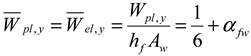
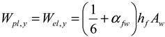
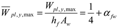
- The importance, calculation, and application of three types of plastic section moduli are studied, namely Wpl,nB validity when bimoment BEd is not considered as a constraint, Wpl validity when bimoment BEd is considered as a constraint, and Wpl,max. This was shown for all three plastic section moduli as follows: Wpl,y (bending about axis y-y), Wpl,z (bending about axis z-z), and Wpl,w (torsion about axis x), as well as for 14 different shapes of cross-sections. The mutual relationship of different plastic section moduli was explained on open, quasi-open, and closed thin-walled cross-sections with two axes of symmetry, one axis of symmetry, being point-symmetric, and cross-sections without an axis of symmetry.
- (c)
- All non-dimensionless properties of a monosymmetric I-section, channel, and Z-section, including all kinds of plastic section moduli which cannot be found in static tables and are not calculated by commercial programs, are determined. Non-dimensional properties are very convenient for parametrical studies and the optimalization of cross-sections.
- (d)
- Formulae for channel profiles in the plastic state loaded by a combination of My,Ed with positive bimoment BEd and My,Ed with negative bimoment BEd are used and are convenient for standards.
- (e)
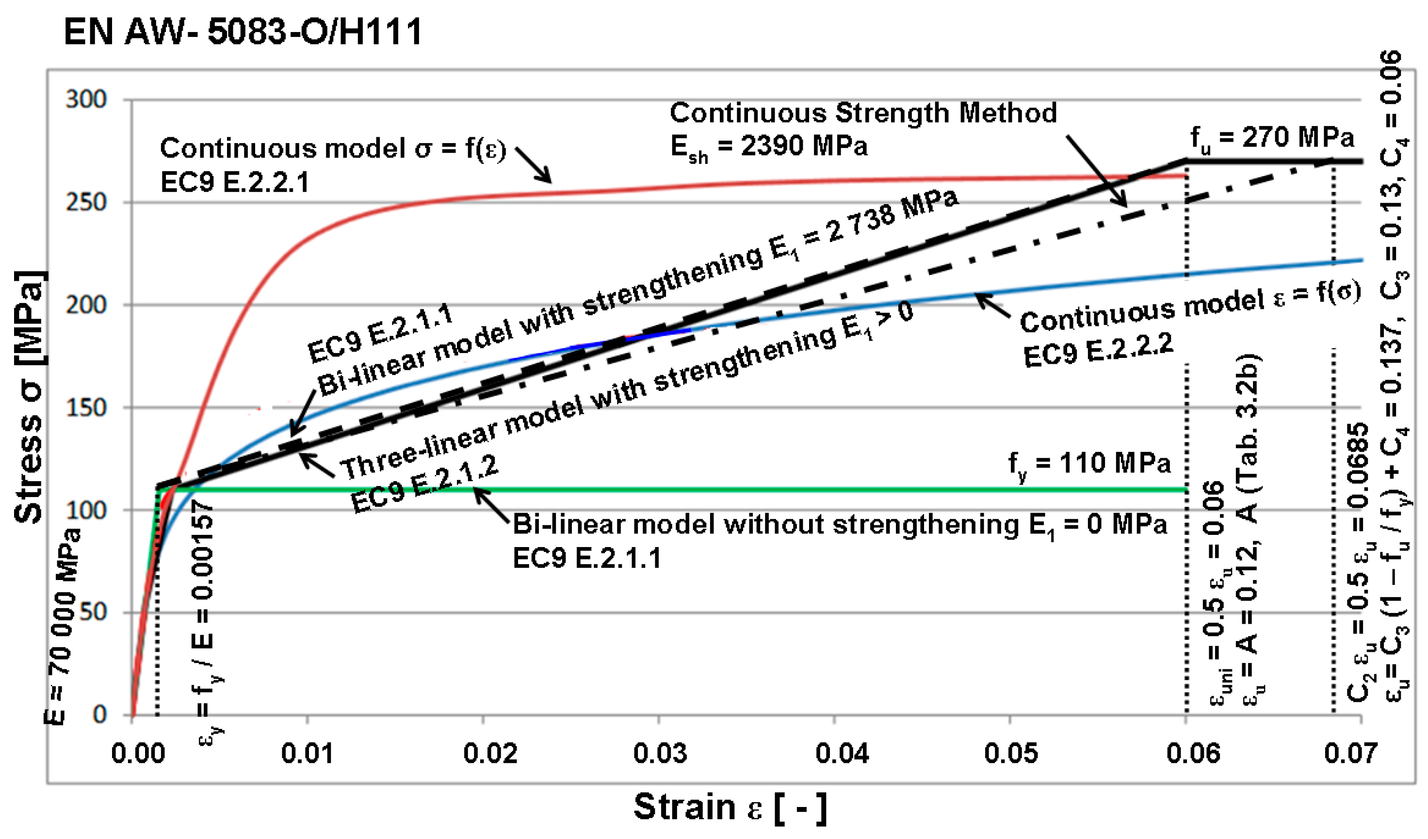
- The influence of bilinear stress–strain diagrams without and with strengthening for both aluminum and steel I-shaped profiles is determined.
- (f)
- Problems in the second generation of Eurocode EN 1993-1-1:2022 and their solution by authors of the paper are provided.
- (g)
- Formulae of MathCad calculations which were removed from prEN 1993-1-3:2024 are included, this time also including an oblique hollow section. They are the result of Torsten Höglund, the main author of EN 1999-1-1:2023.
2. Plastic Design in Metal Eurocodes EN 1993-1-1:2022 [14] and EN 1999-1-1:2023 [15]
2.1. Advantages of Plastic Analysis and Assumptions for Plastic Analysis Applications
- (a)
- It fully expresses the actual behavior of the structures;
- (b)
- It allows for the attainment of the same safety for a structure and its elements;
- (c)
- It often simplifies the analysis of current structures;
- (d)
- It is a source of substantial material and cost economies;
- (e)
- It provides a summary of important assumptions for the use of plastic design;
- (f)
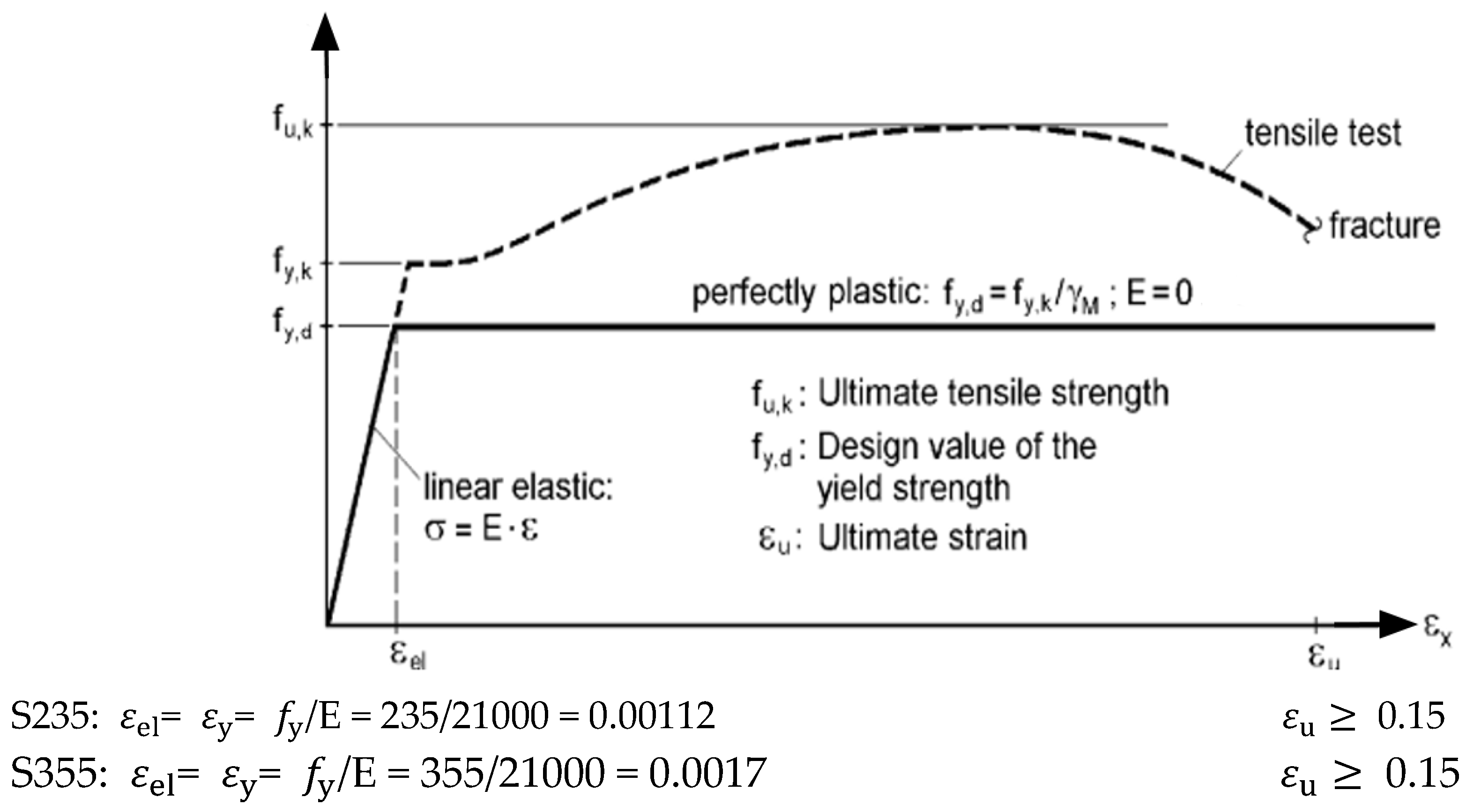
- Steel and aluminum are regarded as an ideal elastoplastic material, the behavior of which is described by the idealized stress–strain diagram with sufficient accuracy (see Figure 2);
- (g)
- The material behaves identically in tension and simple compression;
- (h)
- The plastic resistance of the structural member at the cross-sections with a non-uniform distribution of longitudinal strains is exhausted due to the formation of plastic hinges, which are not capable of resisting any further increase in load;
- (i)
- The deformations of structures up to the limit of the plastic load-bearing capacity are so small that equilibrium of forces can be investigated for an undeformed structure. The expressions for virtual work can also be formulated with the assumption of small deformations;
- (j)
- The longitudinal strains of the cross-sections are distributed linearly in the cross-section elements. Vlasov’s hypothesis about the non-deforming shape of the cross-section is adopted;
- (k)
- For a complex state of stress, Huber–Mises–Hencky’s condition is usually applied as a condition of plasticity;
- (l)
- When the plastic load-bearing capacity or the deflections of statically indeterminate structures are being determined, it is assumed that the plastic strains are concentrated at the most highly stressed cross-sections—the plastic hinges. After the hinge mechanism has been formed, the curvature of elements between the hinges is supposed to remain unchanged;
- (m)
- Random imperfections are not taken into account;
- (n)
- Failure due to local and global instability of members is prevented by structural measures;
- (o)
- The structural connections are rigid to the extent that they are capable of transferring the redistributed effects.
2.2. EN 1993-1-1:2022 [14]
- (a)
- The ratio of ultimate tensile strength to yield strength is ;
- (b)
- The elongation at failure is not less than .
2.3. EN 1999-1-1:2023 [15]
2.3.1. Plastic Section Modulus [15]
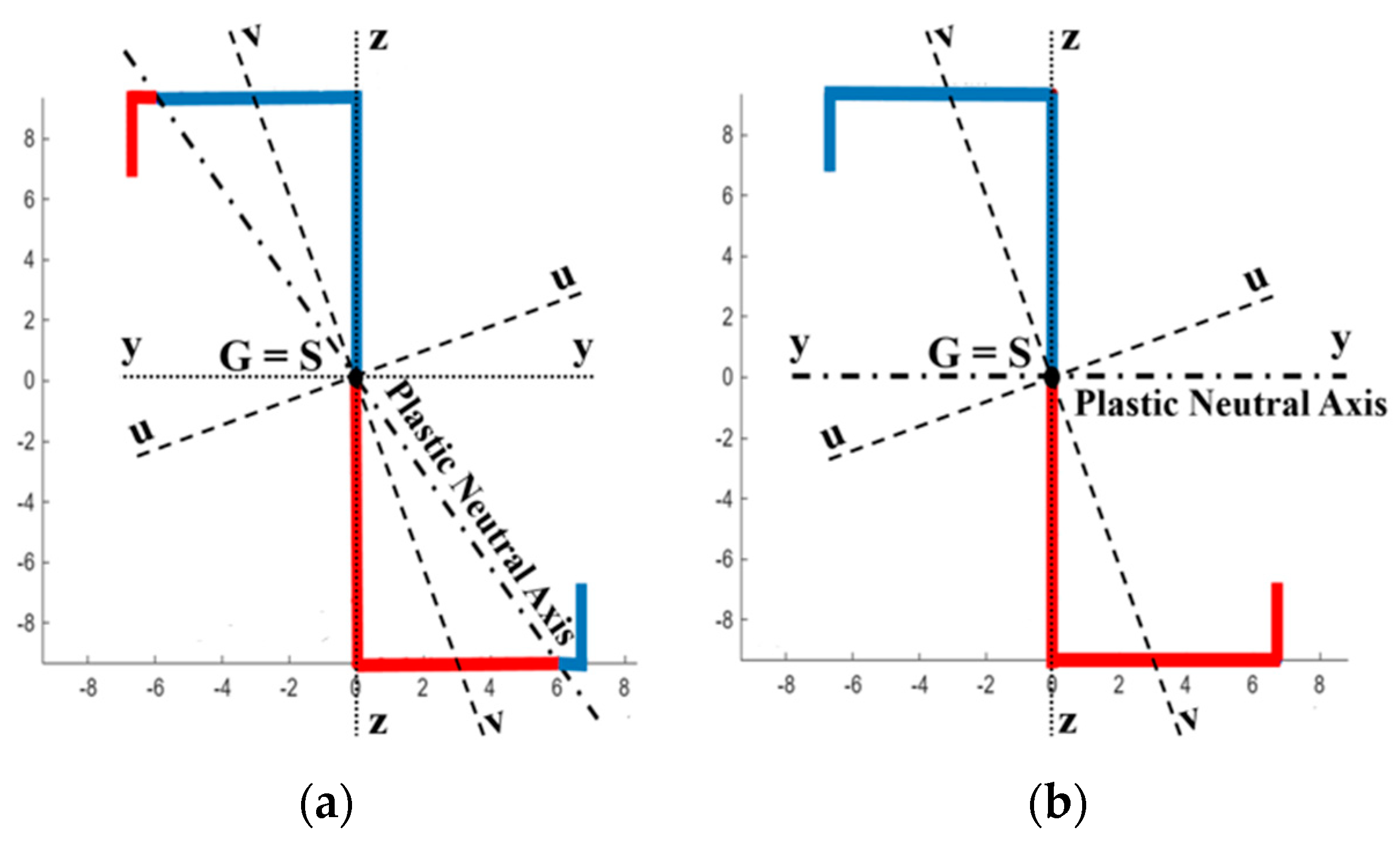
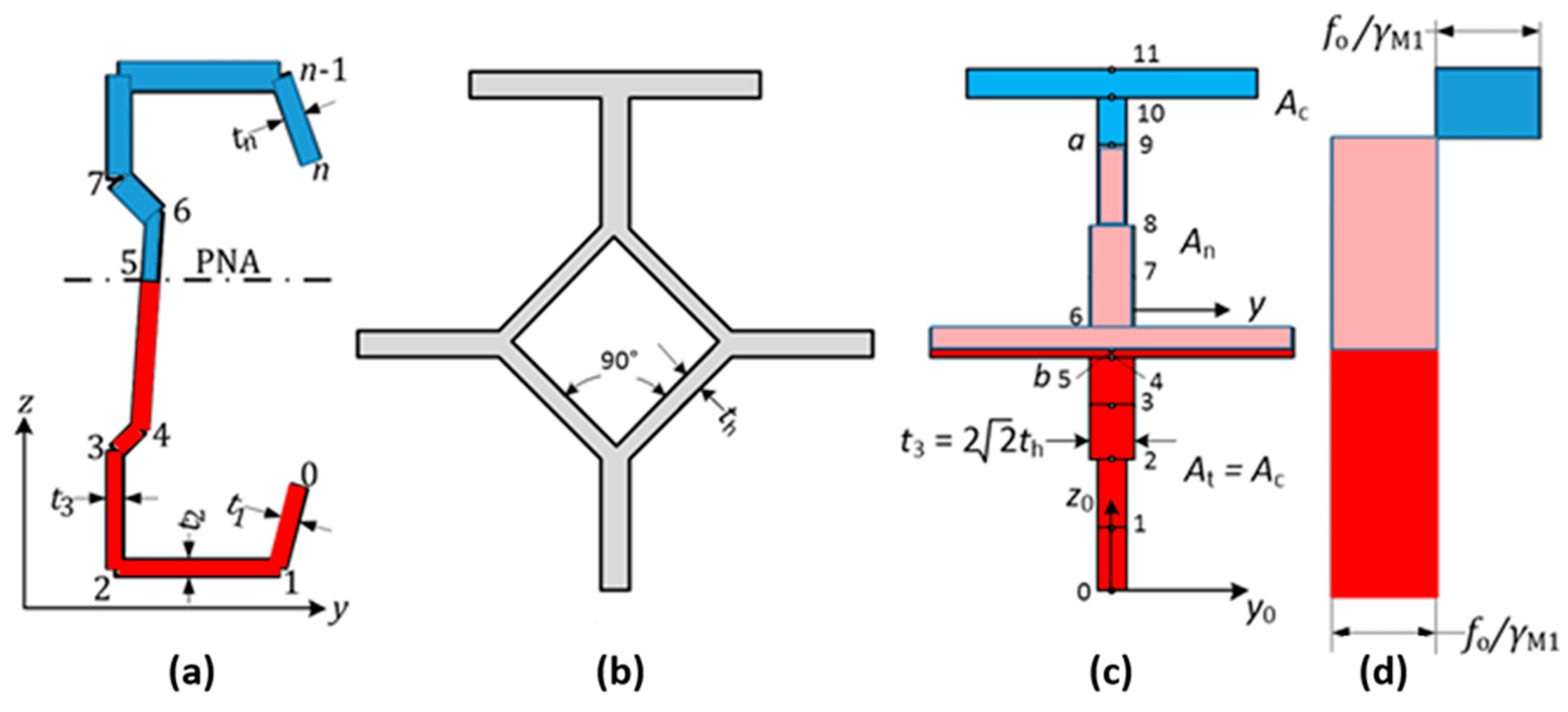
- (1)
- Add an extra node in the part that will be crossed by the plastic neutral axis (PNA);
- (2)
- Define the PNA so that the areas above and below the PNA are the same (=A/2);
- (3)
- Replace the thickness ti below the PNA with the negative value −ti;
- (4)
- The plastic section modulus Wpl,y is then given by Formula (1). See also Appendix A below.
2.3.2. Plastic Interaction Formula
- (1)
- Choose a node a (=9 in Figure 3c) above which there is compression stress;
- (2)
- Calculate the area Ac above this node a;
- (3)
- Add an extra node b (=5 in Figure 3c) on the tension side, placed so that the area At below this node is the same as Ac;
- (4)
- Set the thickness to −ti for parts 1 to b and 0 for parts b + 1 to a;
- (5)
- Calculate the reduced plastic section modulus with Formula (1);
- (6)
- Calculate the area An = A − 2Ac;
- (7)
- A point on the interaction diagram is now given by MRd = Wpl,y fo/γM1 and NRd = An fo/γM1;
- (8)
- Repeat the procedure for the other nodes a;
- (9)
- If the bending moment resistance is searched for a specific axial force, then the node a should be chosen so that Ac = 0.5(A − NRd/(fo/γM1)).
- (a)
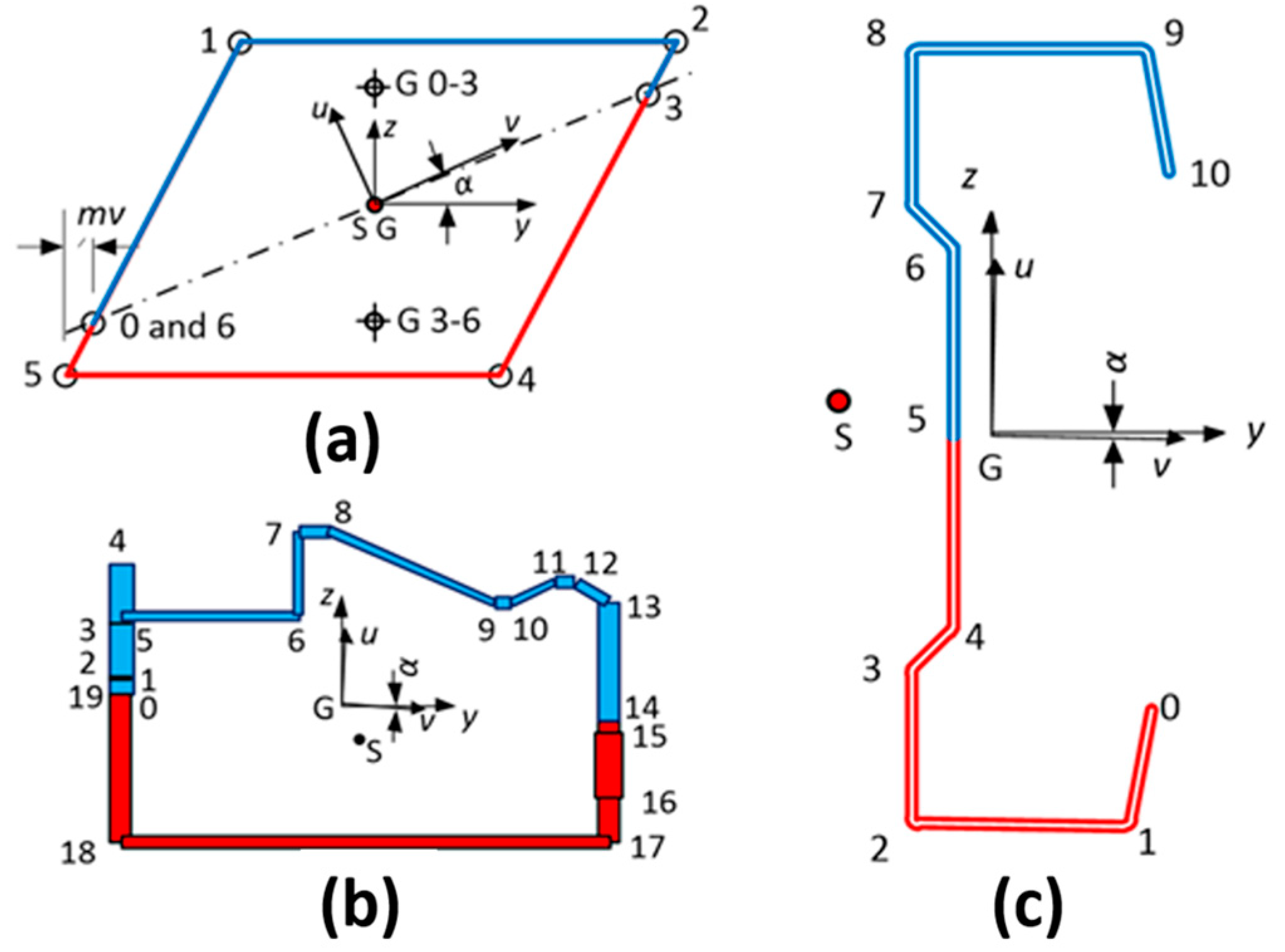
- Divide the cross-section into n parts. Number the parts 1 to n. Insert nodes between the parts. Number the nodes from 0 to n. Part i is then defined by nodes i − 1 and i. Give the nodes, coordinates, and (effective) thickness. j = 0 … n are nodes and i = 1 … n are cross-section parts. Note that y − z is an arbitrary coordinate system with the origin usually not in the center of gravity and that the principal axes are here denoted as and .
- (b)
- Calculate the following geometrical magnitudes:
3. Basis of Theory
- (1)
- Without considering bimoment as a constraint: Wpl,zy,nb and Wpl,z,nB.
- (2)
- Considering bimoment as a constraint: Wpl,y, Wpl,z and Wpl,w.
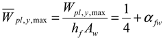
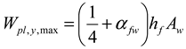
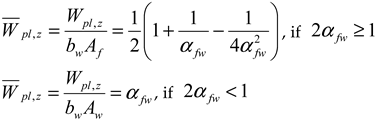
- (3)
- Maximum: Wpl,y,max, Wpl,z,max, and Wpl,w,max.
- (1)
- thinwallsectiongeneral was used to compute values considering bimoment as a constraint and maximum values.
- (2)
- thinwallsectionopenclosed was used to compute values without considering bimoment as a constraint.
3.1. Method 1 to Obtain Plastic Parameters
3.2. Method 1 to Obtain Interaction Diagram

| Case 1: Without Considering Bimoment B as a Constraint | Case 2: Considering Bimoment B as a Constraint | |
|---|---|---|
| Maximize | ξ | ξ |
| Constraint | ||
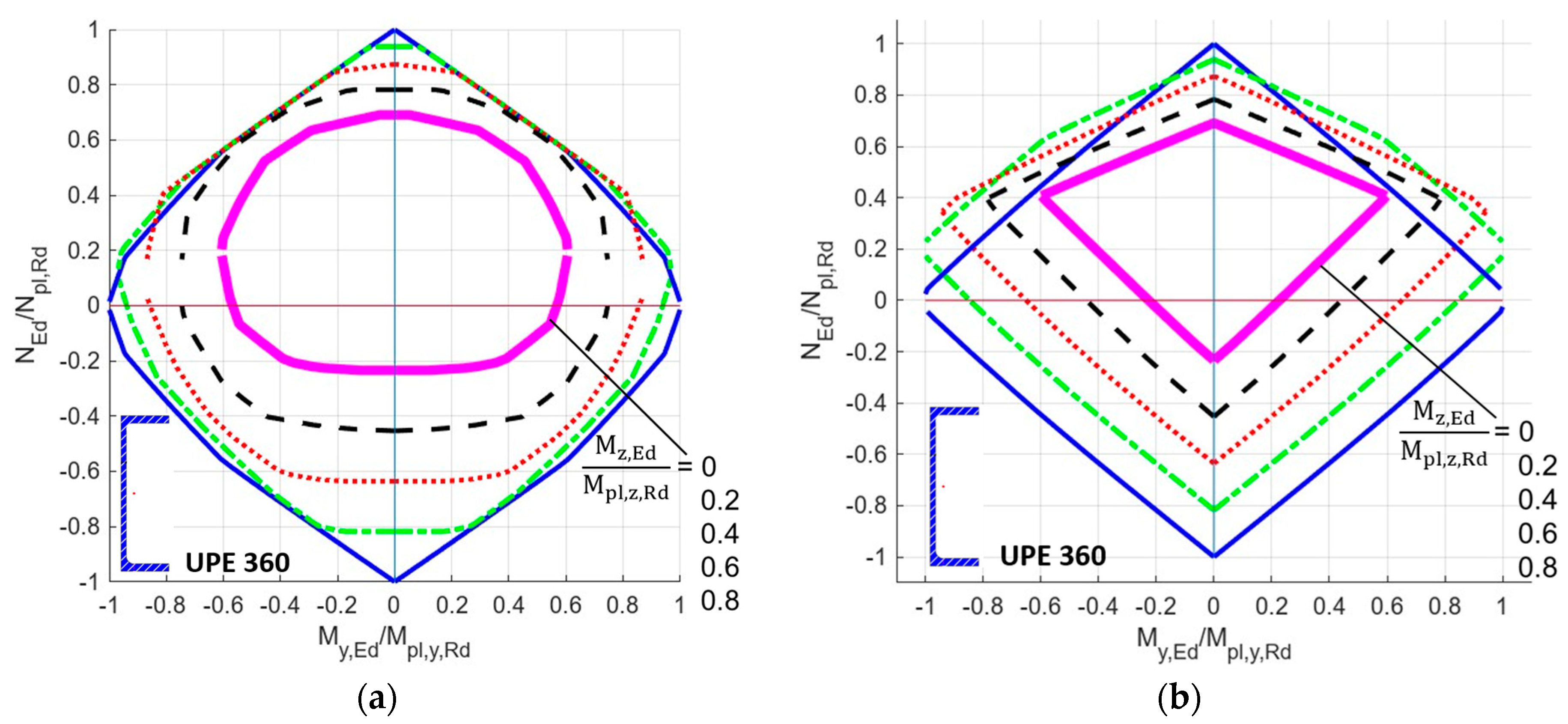
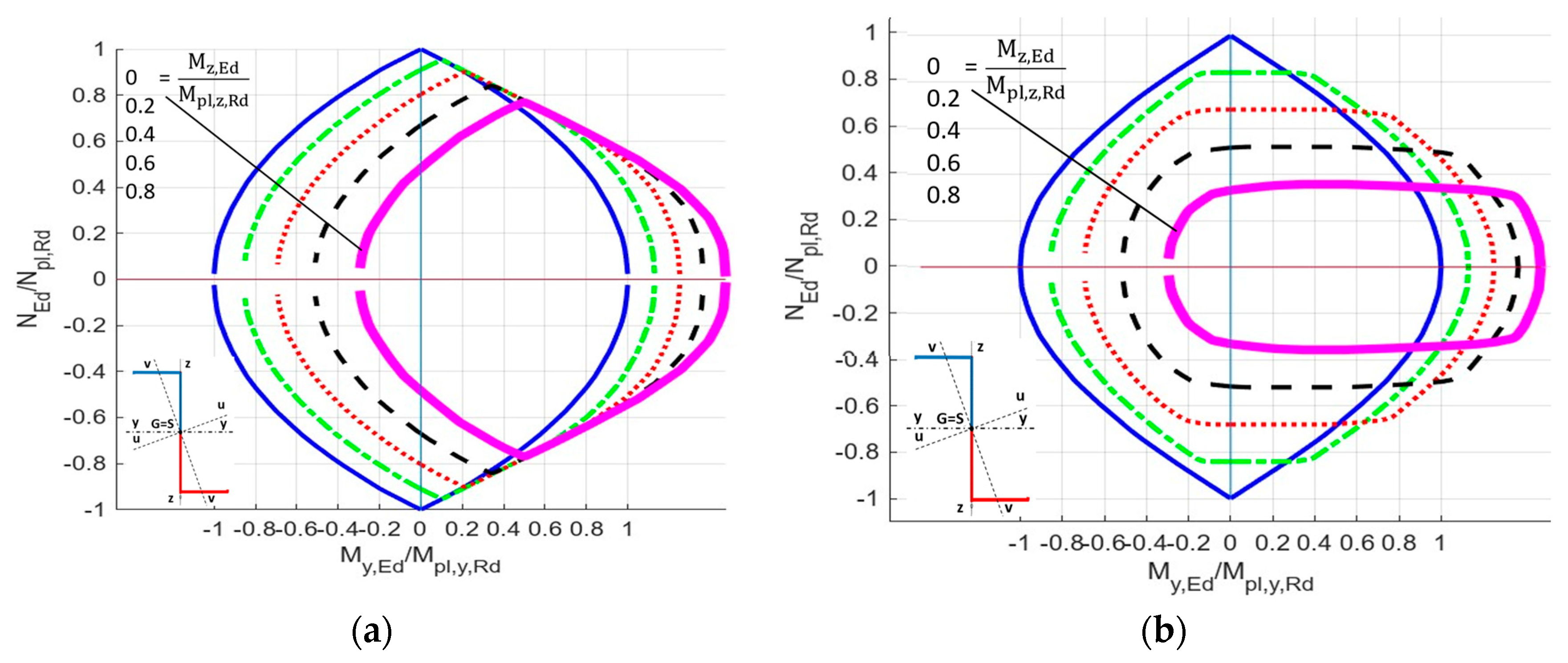
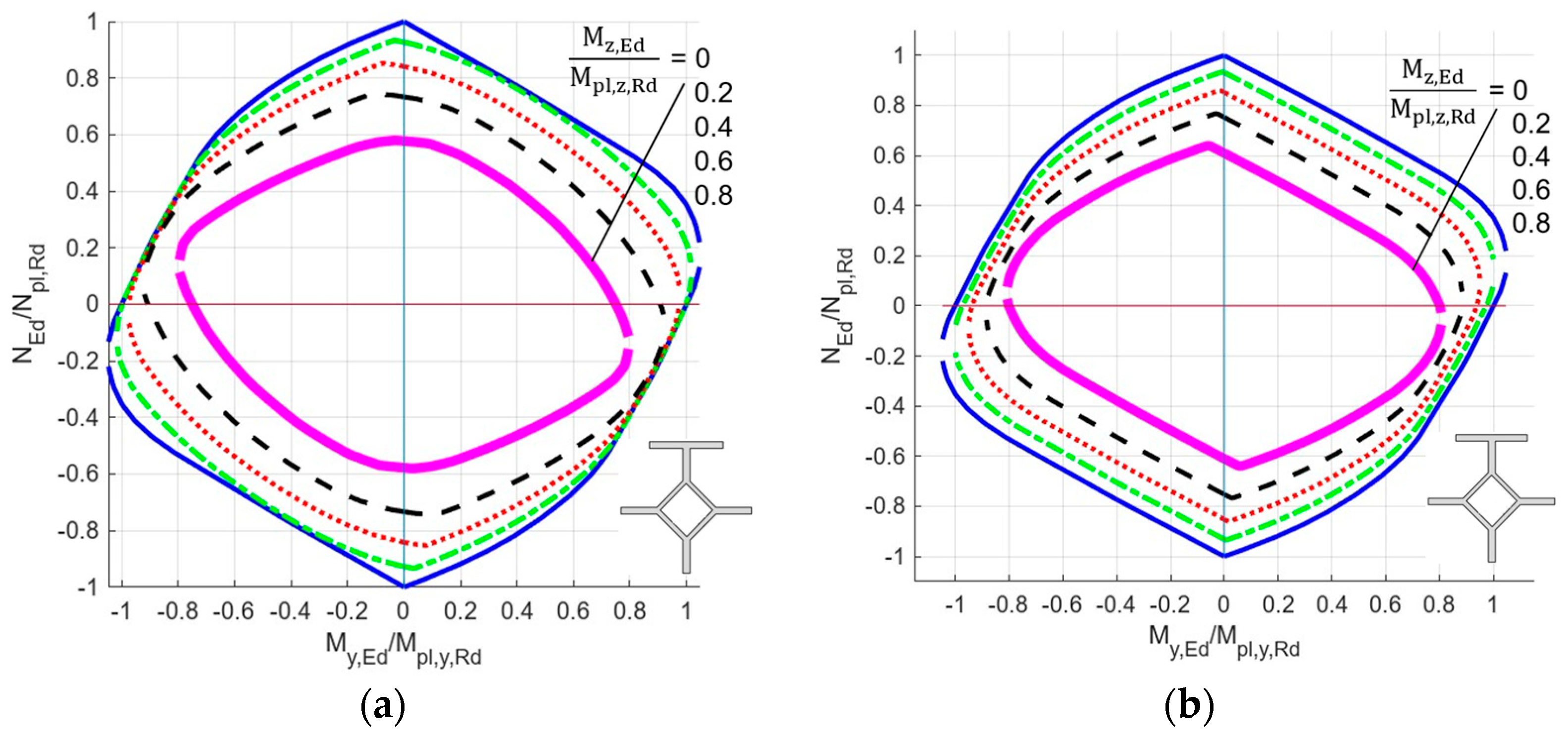
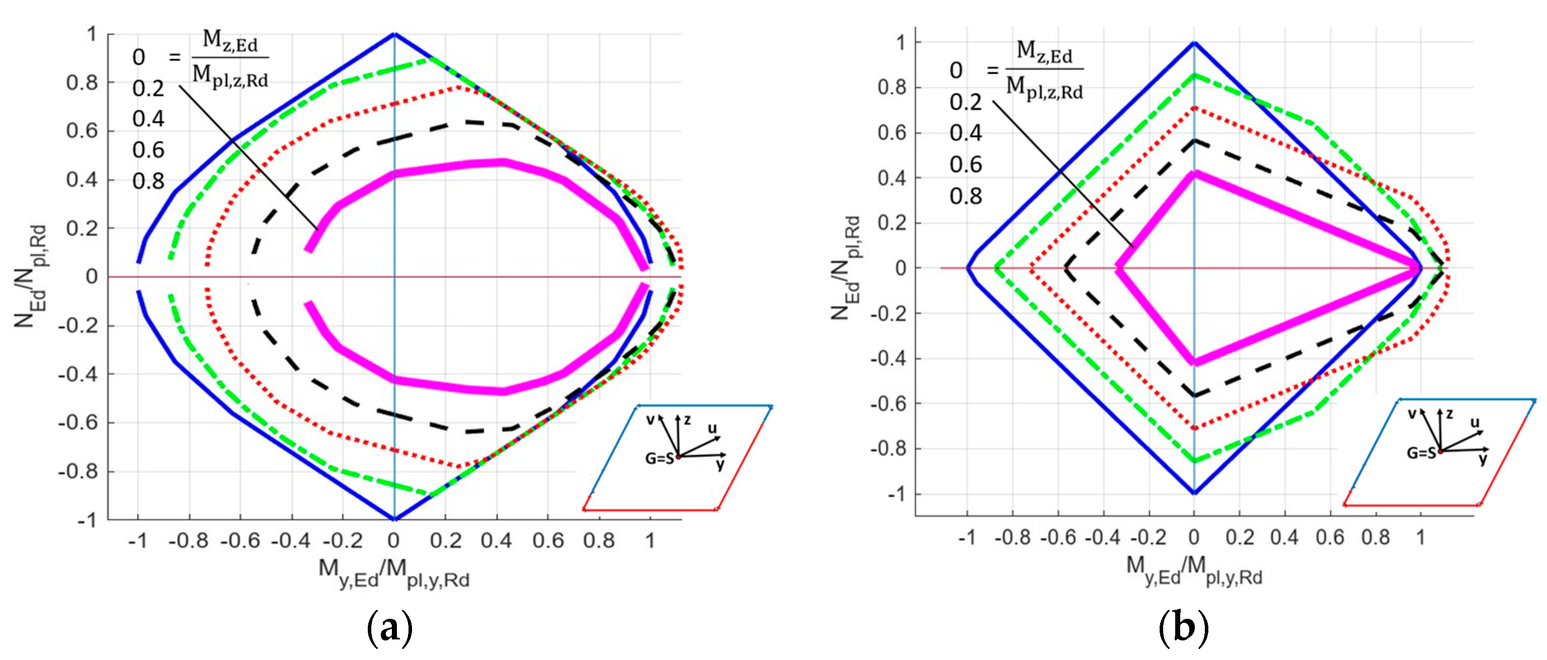
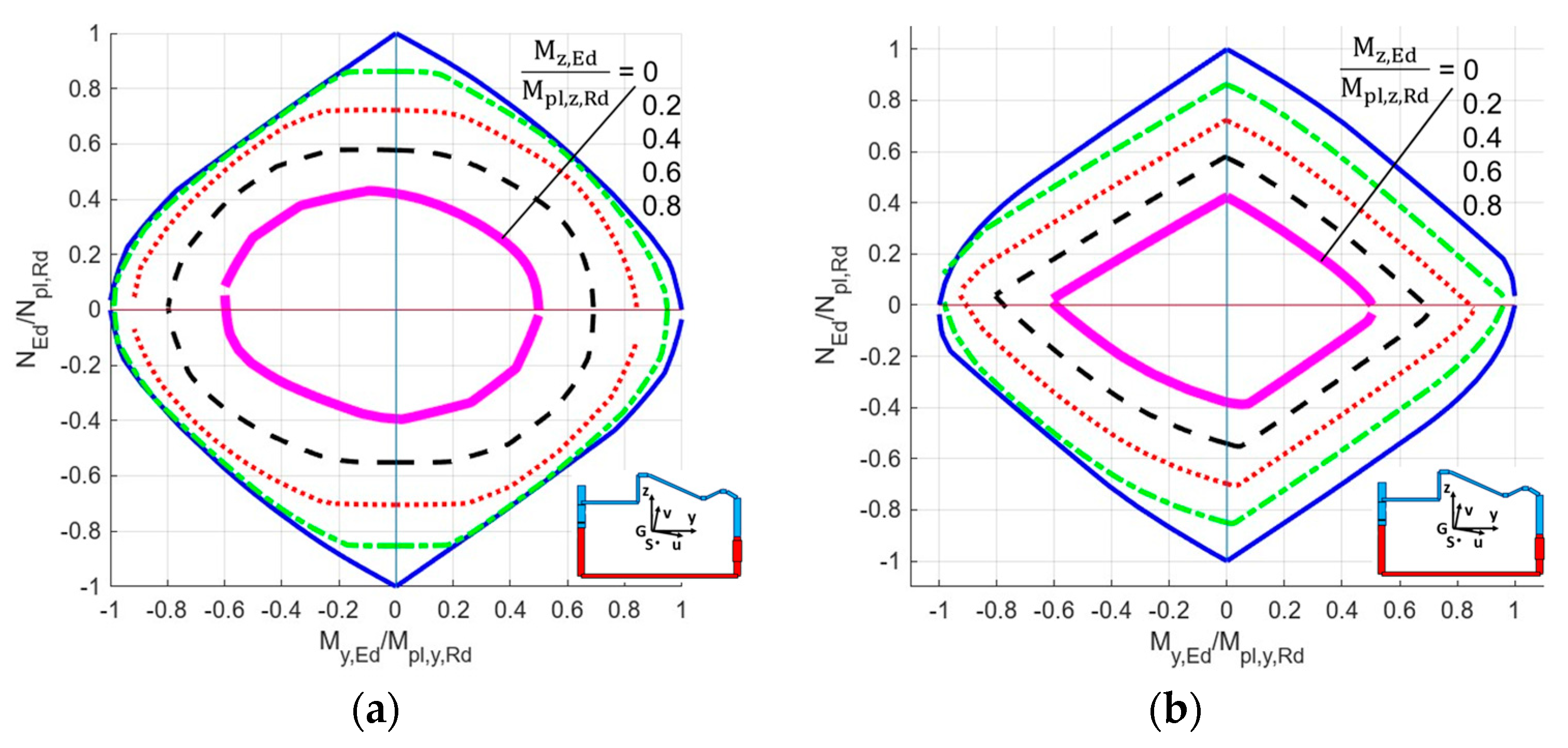
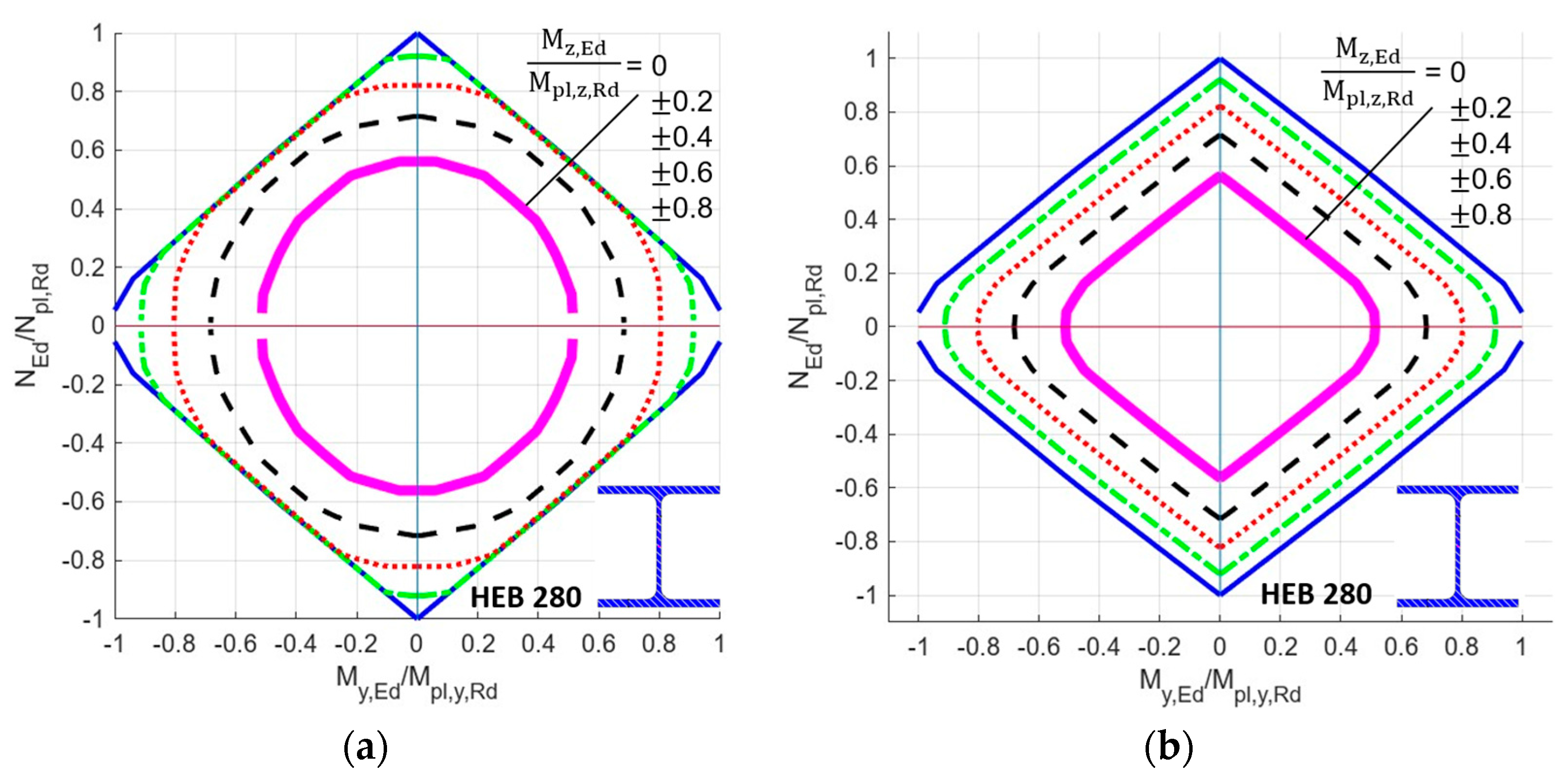
4. Numerical Results. Comparisons of Results of Various Ways of Calculation
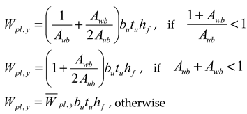
- (a)
- Wpl,y,nB, [Wpl,y], (Wpl,y), and Wpl,z,nB (see columns I.a, I.b, I.c, II.) for the case when bimoment is not (index nB) considered as a constraint. The values in brackets [ ], ( ) in the columns I.b and I.c, respectively, are calculated using formula (G.39) given in Annex G, EN 1999-1-1:2023 [15]; here, it is Formula (1). Computer software MathCad was employed for bracket value calculations. Corner details in column I.b in the calculation of [..] values are (a) + (d) according to Figure 4. Corner details in column I.c in the calculation of (..) values are (b) + (c) according to Figure 4. See the consequences described before Figure 4.
- (b)
- Wpl,y, Wpl,z, and Wpl,w (see columns III., IV., V.) for the case when bimoment is considered as a constraint.
- (c)
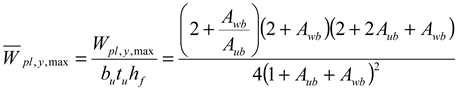
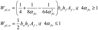
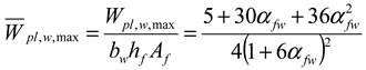
- Wpl,y,max, Wpl,z,max, and Wpl,w,max (see columns VI., VII., VIII.) are also considered. These values may be achieved only if the given internal force exists with some other concomitant internal force. See Table 13a,b for the monosymmetric I-shaped section, Table 14a,b for the channel section, and Table 15a,b for the Z-section.
- (a)
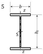
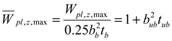
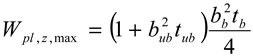
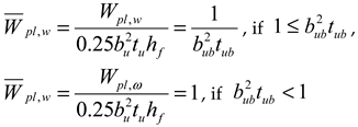
- For doubly symmetric sections (No. 5, 8):Wpl,y = Wpl,y,nB = Wpl,y,max; Wpl,z = Wpl,z,nB = Wpl,z,max; Wpl,w = Wpl,w,max;
- (b)
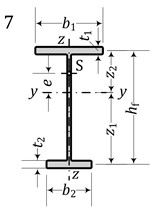
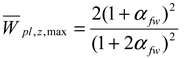
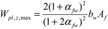
- For monosymmetric sections with axis of symmetry z (No. 2, 7, 11):Wpl,y = Wpl,y,nB < Wpl,y,max; Wpl,z < Wpl,z,nB = Wpl,z,max; Wpl,w < Wpl,w,max;
- (c)
- For monosymmetric sections with axis of symmetry y (No. 3, 4, 6):Wpl,y < Wpl,y,nB = Wpl,y,max; Wpl,z = Wpl,z,nB < Wpl,z,max; Wpl,w < Wpl,w,max;
- (d)
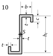
- For point-symmetric sections (9, 10), Figure 8:Wpl,y = Wpl,y,nB < Wpl,y,max; Wpl,z = Wpl,z,nB < Wpl,z,max; Wpl,w < Wpl,w,max;
- (e)
- Asymmetric sections are No. 1, 12, 13, and 14;
- (f)
- For non-warping cross-sections or for cross-sections with negligible warping through the element thicknesses, the calculation of Wpl,y, Wpl,z, and Wpl,w for bimoment BEd considered as a constraint is not possible. See No. 1 and 2, columns III.–V.
5. Recommendations
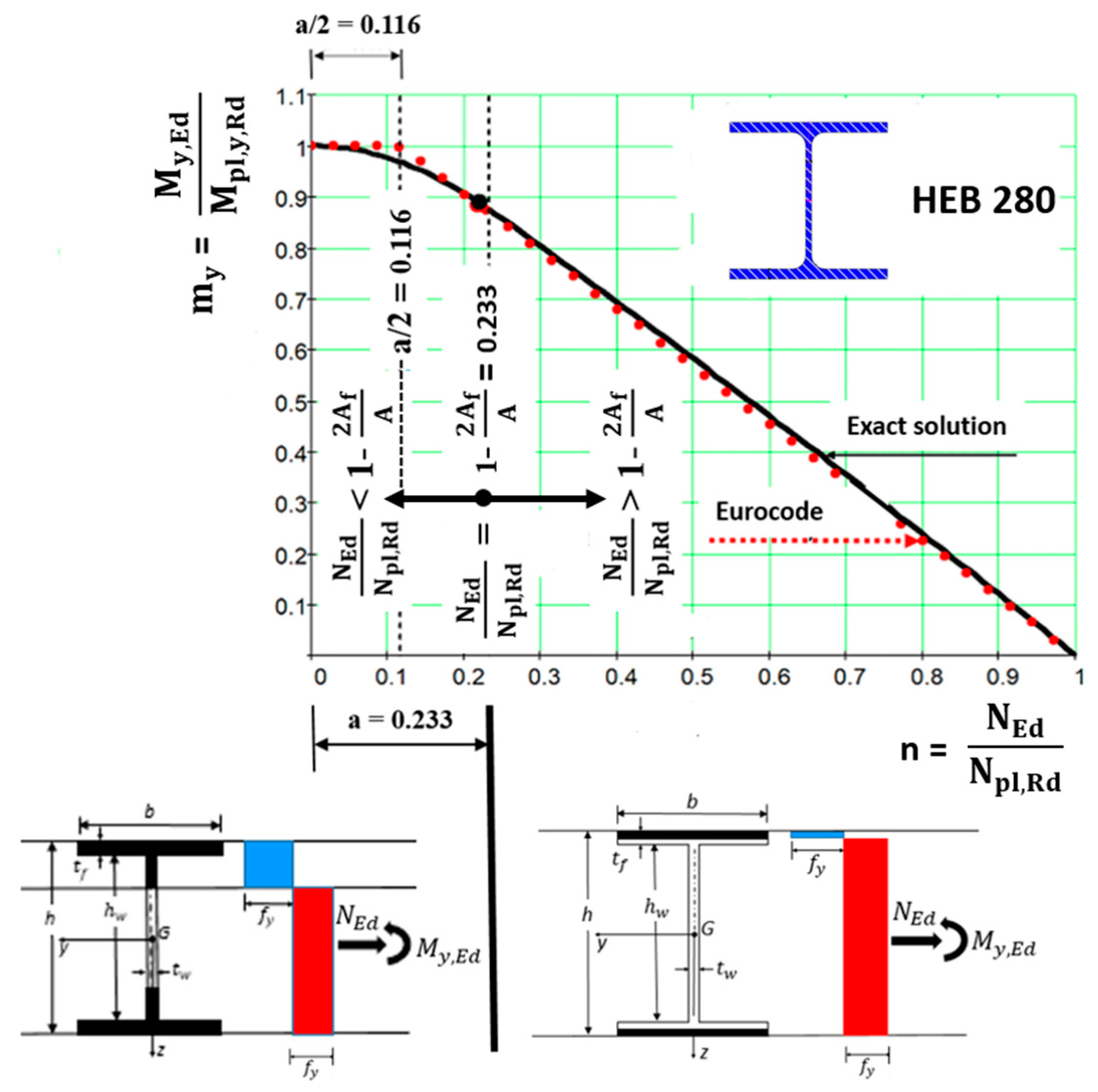
5.1. Double Symmetric Steel I-Shaped Cross-Section of Class 1 or Class 2 Under Combination of Axial Force and Bending Moment NEd + My,Ed
- (a)
- The approximate formula (8.48) after substitution into formula (8.43) has the form
- (b)
- Formula (20) gives results on the dangerous side for small values of the axial force (error is up to approximately 7%). This problem can be solved by replacing the approximate Eurocode formulae (8.43) and (8.48), which is (20) here, with more accurate formulae derived by Baláž [13]. For I-shaped sections, we present the exact my−n interaction formulae in two versions as follows:
- (b1)
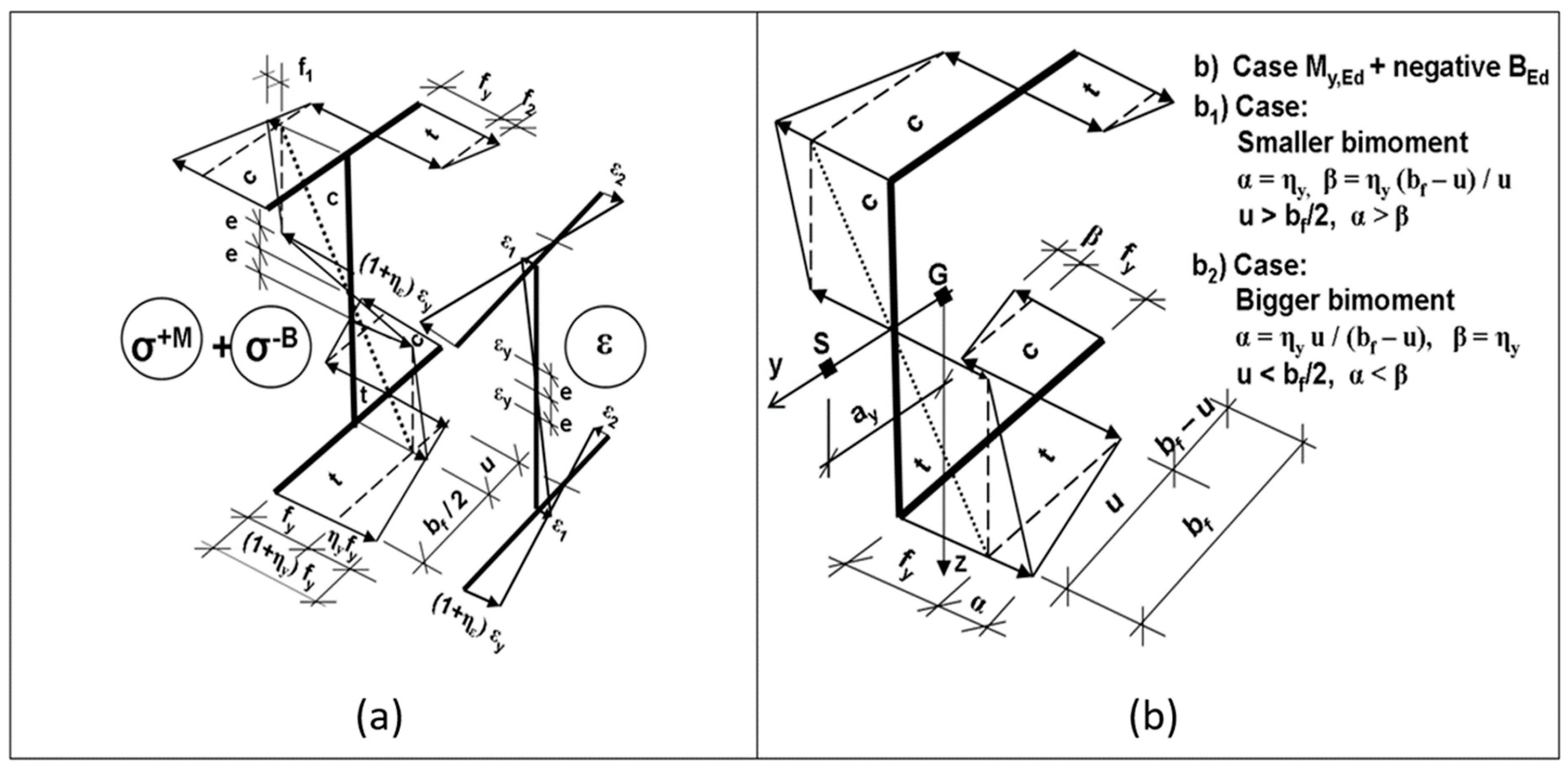
- For a cross-section consisting of three rectangles, two independent dimensionless parameters appear in the formulae. The graphic interpretation is in Figure 13 and Figure 14. Formula (24) is valid for smaller values , when the plastic neutral axis lies in the web of the I-section (see bottom left part of Figure 14). Formula (25) is valid for larger values , when the plastic neutral axis lies in the flange of the I-section (see bottom right part of Figure 13). In the case of , the plastic neutral axis is located in the point of contact of the flange with the web.
- (b2)
- For the cross-section consisting of the midlines with thicknesses, only one independent dimensionless parameter appears in the formulae.

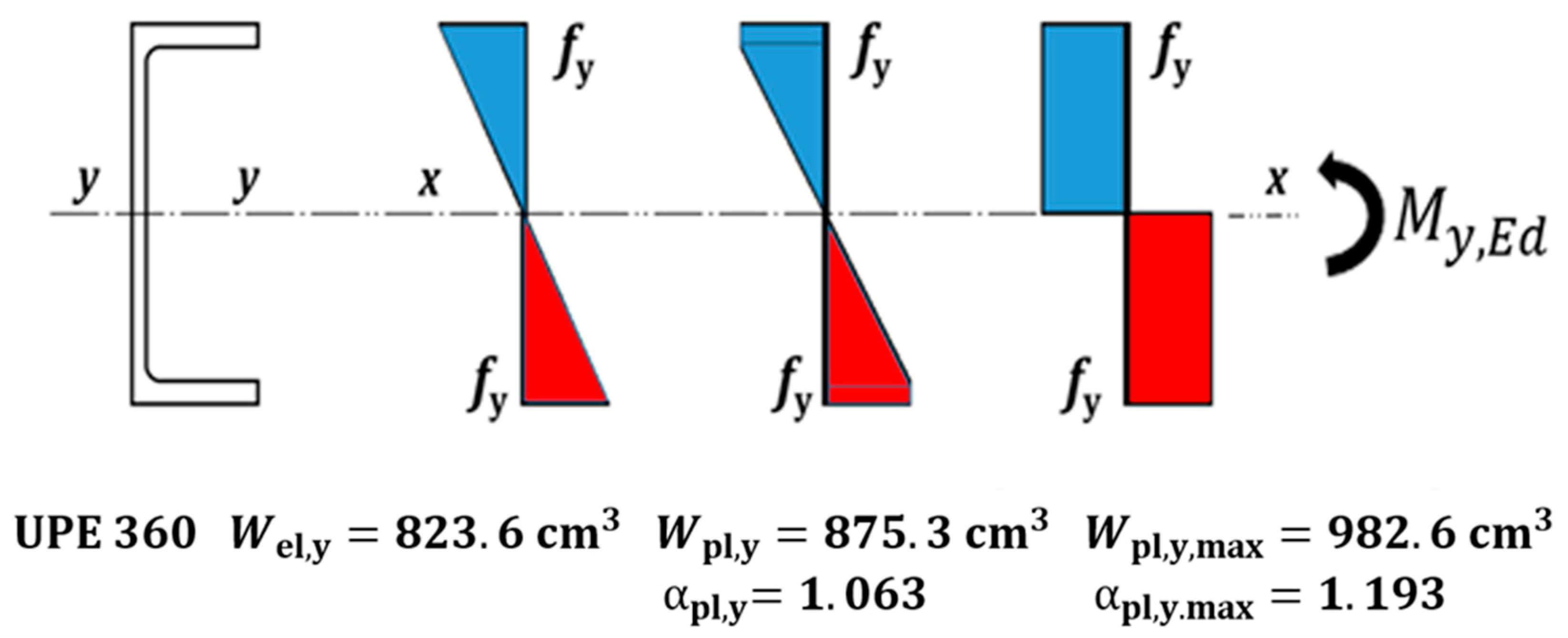
5.2. Plastic Reserve of Steel Channel Cross-Section Under Bending Moment My,Ed
5.3. Double-Symmetric Aluminum and Steel I-Shaped Profiles Under Combination of Bending Moment About y-y Axis and Bimoment My,Ed + BEd
- (i)
- The elastic limit state is defined by the following linear interaction formula:
- (iii)
- With strengthening ηy = 0.25 (Figure 18):
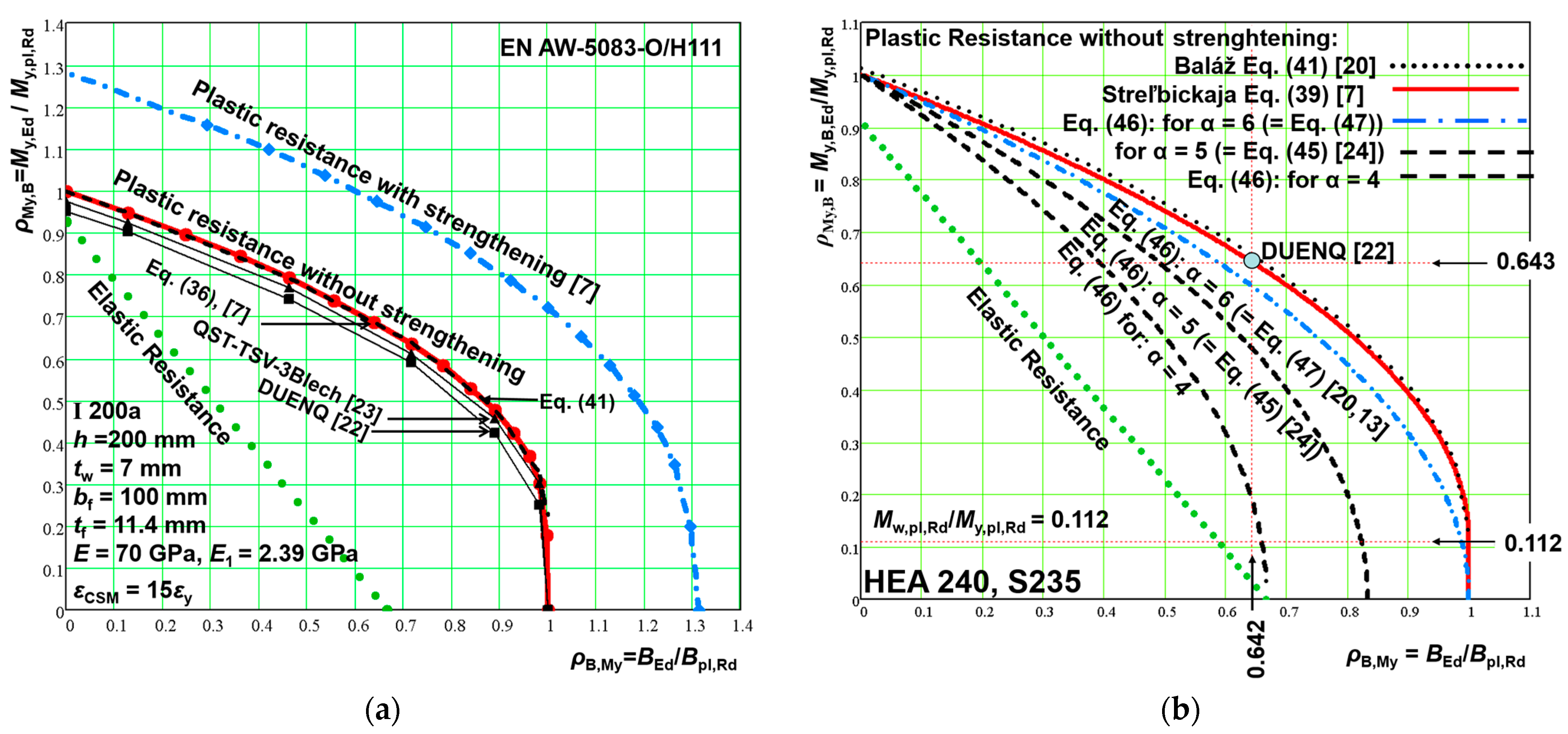
5.4. Steel Channel Cross-Section Profile Under Combination of Moment My,Ed and Bimoment BEd
Channel Cross-Section Resistance Calculation According to Streľbickaja [7]
- (i)
- The elastic limit state is defined by the linear interaction formula (see Equation (35)).
- (iii)
- With strengthening ηy = 0.25 (Figure 19):
6. Conclusions
Author Contributions
Funding
Data Availability Statement
Conflicts of Interest
Appendix A
Example of y-Axis Plastic Section Modulus for an Oblique Hollow Section, See Also [32]
References
- Kazinczy, G. Beton und Eisen; W. Ernst & Sohn: Berlin, Germany, 1933; Volume 32, pp. 74–80. [Google Scholar]
- Kurrer, K.-E. Hermann Maier-Leibnitz (1885–1962): Wegbereiter des Industriebaus der klassischen Moderne. Stahlbau 2005, 74, 623–634. [Google Scholar] [CrossRef]
- Maier-Leibnitz, H. Beitrag zur Frage der tatsächlichen Tragfähigkeit einfacher und durchlaufender Balkenträger aus St37 und aus Holz. Die Bautech. 1928, 6, 11–14. [Google Scholar]
- Maier-Leibnitz, H. Versuche mit eingespannten und einfachen Balken von I-Form aus St 37. Bautechnik 1929, 7, 313–318, Stahlbau. 1936. [Google Scholar]
- Beedle, L.S.; Thurlimann, B.; Ketter, R.L. Plastic Design in Structural Steel; Lecture Notes, Summer Course, Lehigh University, Bethlehem, PA, USA; AISC: New York, NY, USA, 1955. [Google Scholar]
- Mrázik, A.; Škaloud, M.; Tocháček, M. Plastic Design of Steel Structures; Ellis Horwood Limited: Chichester, UK, 1986. [Google Scholar]
- Strel’bickaja, A.I. Investigation of Resistance of Thin-Walled Columns Behind Yield Strength; Publishing House of AN USSR: Kyiv, Ukraine, 1958. (In Russian) [Google Scholar]
- Kindmann, R.; Frickel, J. Grenztragfähigkeit von häufig verwendeten Stabquerschnitten für beliebige Schnittgrößen. Stahlbau 1999, 68, 817–828. [Google Scholar] [CrossRef]
- Kindmann, R.; Frickel, J. Elastische und Plastische Querschnittstragfähigkeit Grundlagen, Methoden, Berechnungsverfahren, Beispiele; Mit CD-ROM: RUBSTAHL Lehr-und Lernprogramme; Ernst & Sohn, Wiley Company: Berlin, Germany, 2002. [Google Scholar]
- Osterrieder, P.; Kretzschmar, J. First-hinge analysis for lateral buckling design of open thin-walled steel members. J. Constr. Steel Res. 2006, 62, 35–43. [Google Scholar] [CrossRef]
- Vayas, I. Interaktion der plastischen Grenzschnittgrößen doppelsymmetrischer I-Querschnitte. Stahlbau 2000, 69, 693–706. [Google Scholar] [CrossRef]
- Vayas, I.; Charalampakis, A.; Koumousis, V. Inelastic resistance of angle sections subjected to biaxial bending and normal forces. Steel Constr. 2009, 2, 138–146. [Google Scholar] [CrossRef]
- Baláž, I. EN 1993-1-1:2024; Slovak National Annex to STN. ÚNMS SR: Bratislava, Slovakia, 2024. [Google Scholar]
- EN 1993-1-1:2022; Eurocode 3: Design of Steel Structures. Part 1-1: General Rules and Rules for Buildings. CEN: Brussels, Belgium, 2022.
- EN 1999-1-1:2023; Eurocode 9: Design of Aluminium Structures. Part 1-1: General Structural Rules. CEN: Brussels, Belgium, 2023.
- EN 1993-1-1:2005; Eurocode 3: Design of Steel Structures. Part 1-1: General Rules and Rules for Buildings. CEN: Brussels, Belgium, 2005.
- EN 1999-1-1:2007; Eurocode 9: Design of Aluminium Structures. Part 1-1: General Structural Rules. CEN: Brussels, Belgium, 2007.
- Baláž, I. Slovak Comments to prEN 1993-1-1. Sent to CEN/TC250 SC3 WG1 20.11.2020; ÚNMS SR: Bratislava, Slovakia, 2023. [Google Scholar]
- Gardner, L. The Continuous Strength Method for Steel, Stainless Steel and Aluminium Structural Design. In Proceedings of the Eight International Conference on Steel and Aluminium Structures, Hong Kong, China, 7–9 December 2016. [Google Scholar]
- Baláž, I.; Koleková, Y. Resistances of I- and U-Sections. Combined Bending and Torsion Internal Forces. In Proceedings of the Eurosteel 2017, Copenhagen, Denmark, 13–15 September 2017; Paper No. 13_12_ 772 on USB. pp. 1–10. [Google Scholar]
- Baláž, I.; Koleková, Y. Plastic Resistance of I- and U-section under Bending and Torsion. In Institut für Konstruktion und Entwurf Universität Stuttgrat. Stahlbau, Holzbau und Verbundbau. Festschrift zum 60. Geburtstag von Univ.-Prof. Dr.-Ing. Ulrike Kuhlmann; Ernst & Sohn. A Wiley Brand: Berlin, Germany, 2017; pp. 203–209. [Google Scholar]
- Dlubal Software GmbH. Programm DUENQ (Shape-Thin) 8.07.03.185540 x32; Dlubal Software GmbH: Tiefenbach, Germany, 2016. [Google Scholar]
- Wolf, C.; Frickel, J. Programm QST-TSV-3Blech; Ruhr-Universität Bochum: Bochum, Germany, 2006. [Google Scholar]
- Mirambell, E.; Bordallo, J.; Real, E. Torsion and its interaction with other internal forces in EN 1993-1-1—A new approach. Steel Constr. 2016, 9, 240–248. [Google Scholar]
- Baláž, I.; Kováč, M.; Živner, T.; Koleková, Y. Plastic resistance of H-section to interaction of bending moment My,Ed and bimoment BEd. In Proceedings of the 2nd International Conference on Engineering Sciences and Technologies, High Tatras Mountains, Tatranské Matliare, Slovak Republic, Leiden, The Netherlands, 29 June–1 July 2016; A Balkema Book. CRC Press: Boca Raton, FL, USA; Taylor & Francis Group: Abingdon, UK, 2017; pp. 33–38. [Google Scholar]
- Baláž, I.; Kováč, M.; Živner, T.; Koleková, Y. Plastic resistance of IPE-section to interaction of bending internal forces My,Ed, Vz,Ed and torsion internal forces BEd, Tω,Ed and Tt,Ed. In Proceedings of the 2nd International Conference on Engineering Sciences and Technologies, High Tatras Mountains, Tatranské Matliare, Slovak Republic, Leiden, The Netherlands, 29 June–1 July 2016; A Balkema Book. CRC Press: Boca Raton, FL, USA; Taylor & Francis Group: Abingdon, UK, 2017; pp. 27–32. [Google Scholar]
- Baláž, I.; Koleková, Y.; Agüero, A. Plastic Resistance of Channel Sections under Various Internal Forces. In Proceedings of the AIPC Proceedings, ICNAAM 2022, Crete, Greece, 19–25 September 2022; Volume 3094, p. 170003; 20th International Conference of Numerical Analysis and Applied Mathematics European Society of Computational Methods in Sciences and Engineering (ESCMCE); Symposium: Recent Advances in Numerical Methods and Simulations in Statics and Dynamics of Structures. In Proceedings of the AIP Conference Proceedings, Research Article, 7 June 2024; pp. 170004-1–170004-4. [Google Scholar] [CrossRef]
- Baláž, I.; Koleková, Y.; Agüero, A. Plastic Resistance of Z-Sections under Various Internal Forces. In Proceedings of the 7th World Multidisciplinary Civil Engineering-Architecture-Urban Planning Symposium WMCAUS 2022, Prague, Czech Republic, 5–9 September 2022; Volume 2928, p. 150013. [Google Scholar] [CrossRef]
- Agüero, A.; Baláž, I.; Koleková, Y.; Moroczová, L. New interaction formula for the plastic resistance of I- and H-sections under combinations of bending moments My,Ed, Mz,Ed and bimoment BEd. Structures 2021, 29, 577–585. [Google Scholar] [CrossRef]
- Agüero, A.; Baláž, I.; Koleková, Y.; Lázaro, M. New interaction formula for plastic resistance of channel sections under combinations of bending moments My,Ed, Mz,Ed and bimoment BEd. Structures 2022, 44, 594–602. [Google Scholar] [CrossRef]
- Agüero, A.; Baláž, I.; Koleková, Y.; Lázaro, M. New interaction formula for plastic resistance of Z-sections under combinations of bending moments My,Ed, Mz,Ed and bimoment BEd. Buildings 2023, 13, 1778. [Google Scholar] [CrossRef]
- Höglund, T.; Strömberg, J. Cold-formed members and sheeting. The textbook series Construction in steel–Textbooks for designers. KTH Building Science. Luleå University of Technology. Swedish Institute of Steel Construction. Modul 2006, 7, 1–149. [Google Scholar]


| Maximize | |||
| Constraints | |||
| Maximize | ||||
| Constraints | ||||
| Maximize | ||||
| Constraints | ||||
 |  | ||
 |  | ||
 |  | ||
 | where | 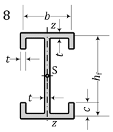 | |
 |  |
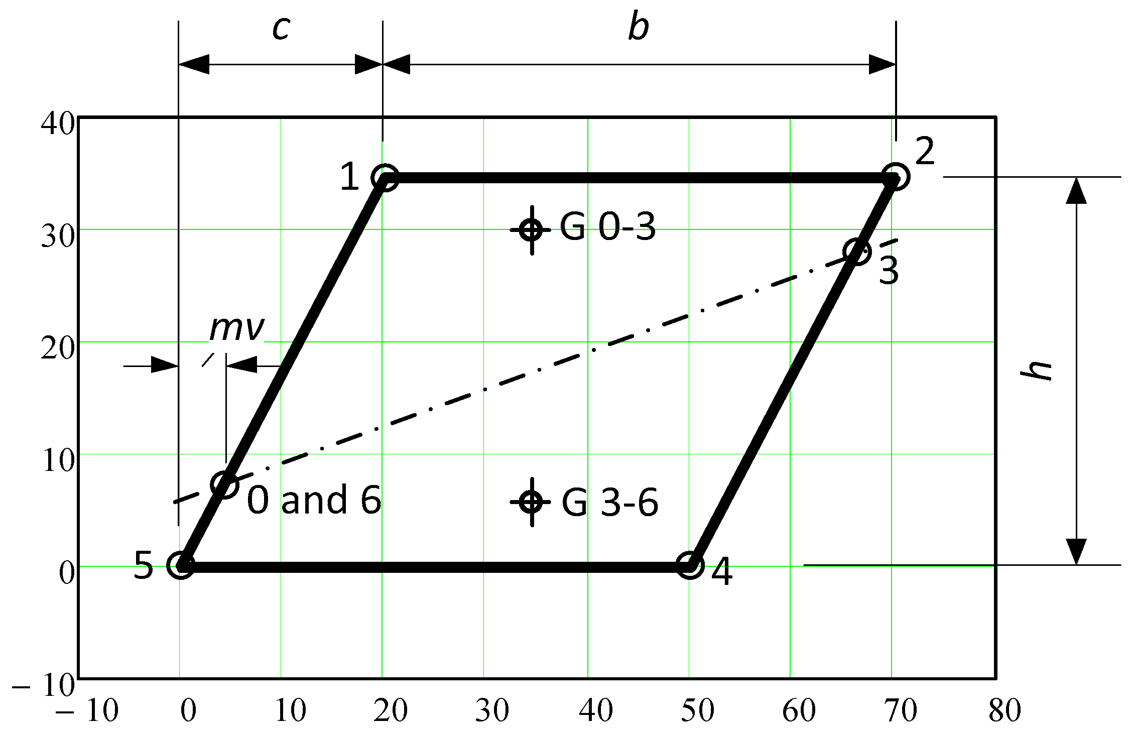
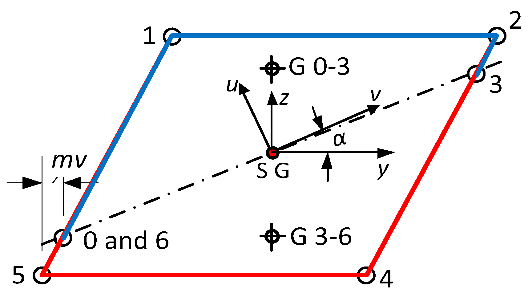
| Nodes, Coordinates y = 0, z [mm], Thicknesses t [mm] | ||||||||||||||||||||||||
|---|---|---|---|---|---|---|---|---|---|---|---|---|---|---|---|---|---|---|---|---|---|---|---|---|
| 0 | 1 | 2 | 3 | 4 | 5 | 6 | 7 | 8 | 9 | 10 | 11 | |||||||||||||
| z | 0 | 20 | 50 | 70 | 90 | 90.86 | 100 | 120 | 140 | 170 | 190 | 200 | ||||||||||||
| t | 10 | 10 | 17 | 17 | 140 | 140 | 17 | 17 | 10 | 10 | 110 | |||||||||||||
| Nodes, Coordinates y, z [mm], t = 0.4 [mm] | |||||||
|---|---|---|---|---|---|---|---|
| 0 | 1 | 2 | 3 | 4 | 5 | 6 | |
| y | 3.775 | 20 | 70 | 66.225 | 50 | 0 | 3.775 |
| z | 6.538 | 34.64 | 34.64 | 28.102 | 0 | 0 | 6.538 |
| Nodes, Coordinates y, z [mm], Thicknesses t [mm] | ||||||||||||||||||||||||||||||||||
|---|---|---|---|---|---|---|---|---|---|---|---|---|---|---|---|---|---|---|---|---|---|---|---|---|---|---|---|---|---|---|---|---|---|---|
| 0 | 1 | 2 | 3 | 4 | 5 | 6 | 7 | 8 | 9 | 10 | ||||||||||||||||||||||||
| y | 1.45 | 1.45 | 1.45 | 1.45 | 1.45 | 1.45 | 24.15 | 24.15 | 27.9 | 48.9 | 51.1 | |||||||||||||||||||||||
| z | 21.784 | 23.784 | 24.3 | 31.3 | 40.2 | 32.75 | 32.75 | 44.75 | 44.75 | 34.7 | 34.5 | |||||||||||||||||||||||
| t | 2.9 | 2.9 | 2.9 | 2.9 | 0 | 1.5 | 1.5 | 1.7 | 1.5 | 1.5 | ||||||||||||||||||||||||
| Nodes, coordinates y, z [mm], thicknesses t [mm] | ||||||||||||||||||||||||||||||||||
| 10 | 11 | 12 | 13 | 14 | 15 | 16 | 17 | 18 | 19 | |||||||||||||||||||||||||
| y | 51.1 | 56.7 | 59.3 | 63.55 | 63.55 | 63.55 | 63.55 | 63.55 | 1.45 | 1.45 | ||||||||||||||||||||||||
| z | 34.5 | 37.5 | 37.5 | 34.6 | 18.043 | 16.3 | 7.3 | 0.85 | 0.85 | 21.784 | ||||||||||||||||||||||||
| t | 1.5 | 1.5 | 1.6 | 2.9 | 2.9 | 3.3 | 2.9 | 1.7 | 2.9 | |||||||||||||||||||||||||
| Nodes, Coordinates y, z [mm], t = 1.4 [mm] | |||||||||||
|---|---|---|---|---|---|---|---|---|---|---|---|
| 0 | 1 | 2 | 3 | 4 | 5 | 6 | 7 | 8 | 9 | 10 | |
| y | 60 | 55 | 0 | 0 | 10 | 10 | 10 | 0 | 0 | 60 | 65 |
| z | 30 | 0 | 0 | 40 | 50 | 100 | 150 | 160 | 200 | 200 | 170 |
| Section | I.a | I.b | I.c | II. | III. | IV. | V. | VI. | VII. | VIII. | |
|---|---|---|---|---|---|---|---|---|---|---|---|
| Bimoment Is Not Considered as a Constraint | Bimoment Is Considered as a Constraint | Wpl,max | |||||||||
| No. | Shape | Wpl,y,nB | [Wpl,y] | (Wpl,y) | Wpl,z,nB | Wpl,y | Wpl,z | Wpl,w | Wpl,y,max | Wpl,z,max | Wpl,w,max |
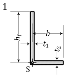
| 1 | L | 27.77 | – | – | 43.15 | – | – | – | 37.47 | 55.16 | – |
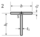
| 2 | T | 44.81 | 44.81 | 44.51 | 23.14 | – | – | – | 51.209 | 23.14 | – |
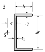
| 3 | U | 269.7 – | 269.7 – | – – | 74.14 – | 241.4 240.6 | 74.14 73.06 | 592.6 591.1 | 269.7 269.7 | 81.31 81.12 | 631.7 610.3 |
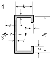
| 4 | U + lips inside | 326.5 | 326.5 | – | 100.96 | 300.6 | 100.96 | 879.8 | 326.5 | 113.4 | 914.9 |
| 5 | I doub. symm. | 281.9 | 281.9 | 270.2 | 46.2 | 281.9 | 46.2 | 388.9 | 281.9 | 46.2 | 388.9 |
| 6 | U + lips outside | 340.8 | 340.8 | – | 100.9 | 298 | 100.9 | 758.7 | 340.8 | 113.4 | 769.3 |
| 7 | I mono symm. | 279.4 | 275.1 | 263.4 | 48.87 | 279.4 | 44.19 | 234.3 | 281.8 | 48.87 | 287.9 |
| 8 | I + lips doub.s | 376.4 | 376.4 | 361.2 | 78. | 376.4 | 78. | 703. | 376.4 | 78. | 703. |
| 9 | Z point symm. | 166.4 – – | – – – | – – – | 64.70 – – | 166.4 162.9 – | 64.70 63.22 – | 683 687.5 – | 269.7 269.7 269.7 * | 77.8 73.13 – | 760. 758.5 – |
| 10 | Z + lips point s. | 205.8 | – | – | 90.9 | 205.8 | 90.9 | 976.5 | 326.4 326.5 * | 107.4 | 1123. |
| 11 | Sect. + diamon. | 219.9 | 214.7 | – | 160. | 219.9 | 147. | 307 | 230. | 160. | 415. |
| 12 | Oblique point s. | 0.866 | 0.863 | – | 1.301 | 0.866 | 1.301 | 0.173 | 0.97 | 1.4 | 0.173 |
| 13 | Irregu-lar sec. | 6.05 | 6.014 | – | 9.954 | 5.955 | 9.933 | 7.022 | 6.09 | 10.05 | 7.227 |
| 14 | Sigma asymm. | 37.30 | 37.97 | – | 9.036 | 34.9 | 8.96 | 95.9 | 38. | 10.5 | 104. |
| Source | Quantity | Results for Various u [cm] and e [cm] Values | |||||||
|---|---|---|---|---|---|---|---|---|---|
| stress–strain diagram with strengthening [7] | Streľbickaja [7] | u [cm] | 5.0 | 4.667 | 3.667 | 2.667 | 1.667 | 0.667 | 0.0 |
| e [cm] | 1.347 | 1.395 | 1.592 | 1.936 | 2.694 | 5.725 | – | ||
| Equation (38) | BEd,s [kNm2] | 0.0 | 0.174 | 0.382 | 0.546 | 0.667 | 0.747 | 0.776 | |
| Equation (37) | My,Ed.s [kNm] | 39.10 | 35.29 | 29.74 | 23.96 | 17.82 | 10.62 | 0.0 | |
| stress–strain diagram without strengthening | Streľbickaja Equation (36) [7] | BEd [kNm2] | 0.0 | 0.076 | 0.273 | 0.423 | 0.526 | 0.581 | 0.591 |
| My.Ed [kNm] | 30.45 | 28.87 | 24.13 | 19.36 | 14.54 | 9.159 | 0.0 | ||
| Equation (40) [20] | My.Ed [kNm] | 30.50 | 28.93 | 24.20 | 19.46 | 14.69 | 9.92 | Mw,Rk = 6.82 | |
| Program QST-TSV-3Blech [23] | My.Ed [kNm] | 29.69 | 28.12 | 23.40 | 18.66 | 13.9 | 9.157 | 0.0 | |
| Program DUENQ [22] | My.Ed [kNm] | 29.0 | 27.5 | 22.6 | 18.0 | 12.9 | 7.6 | 0.0 | |
| Computer Programs | Maximum Internal Force | Corresponding Value |
|---|---|---|
| QST-TSV-3Blech [23] | Mpl,y,Rd,max = 225.452 kNm | BEd,Mmax = BEd,conc = −1.0144 kNm2 |
| DUENQ [22] | BEd,Mmax = BEd,conc ≈ −1.0500 kNm2 | |
| QST-TSV-3Blech [23] | Bpl,Rd,max = │−7.12│ kNm2 > Bpl,Rd = 6.763 kNm2 | MEd,Bmax = MEd,conc = 43.31 kNm |
| DUENQ [22] | Bpl,Ed,max ≈ │−6.68│ kNm2 > Bpl,Rd = 6.763 kNm2 | MEd,Bmax = MEd,conc ≈ 43.31 kNm |
| QST-TSV-3Blech [23] | Mpl,y,Rd = 199.52 kNm | BEd,Mpl = BEd,conc = 0 kNm2 |
| DUENQ [22] | Mpl,y,Rd = 192.00 kNm |
| (a) | |
Relative Plastic Section Moduli
 | Plastic Section Moduli
 |
 |  |
 |  |
 |  |
 |  |
 |  |
 |  |
 | |
 | |
 | |
| (b) | |
 | |
| (a) | |
Relative Plastic Section Moduli
 | Plastic Section Moduli
 |
 |  |
 |  |
 |  |
 |  |
 |  |
 |  |
 | |
 | |
 | |
| (b) | |
 | |
| (a) | |
Relative Plastic Section Moduli
 | Plastic Section Moduli
 |
 |  |
 |  |
 |  |
 |  |
 |  |
 |  |
 | |
 | |
 | |
| (b) | |
 | |
| (a) | |
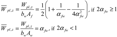
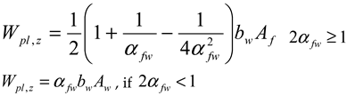
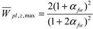
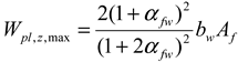
| Relative Plastic Section Moduli | Plastic Section Moduli |
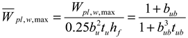
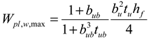
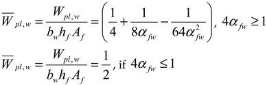
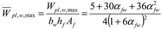
| , , if | , if , if |
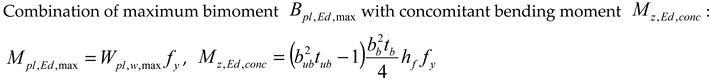
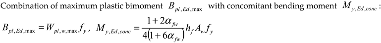
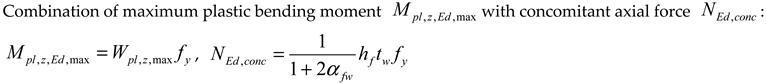
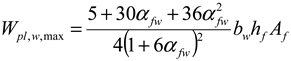
| Combination of maximum plastic bimoment with concomitant axial force : , | |
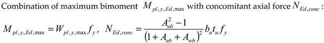
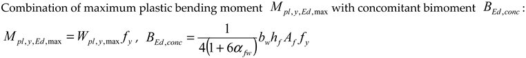
| Maximum plastic bending moment about the y-y axis is concomitant with the maximum plastic bending moment about the z-z axis . | |
| (b) | |
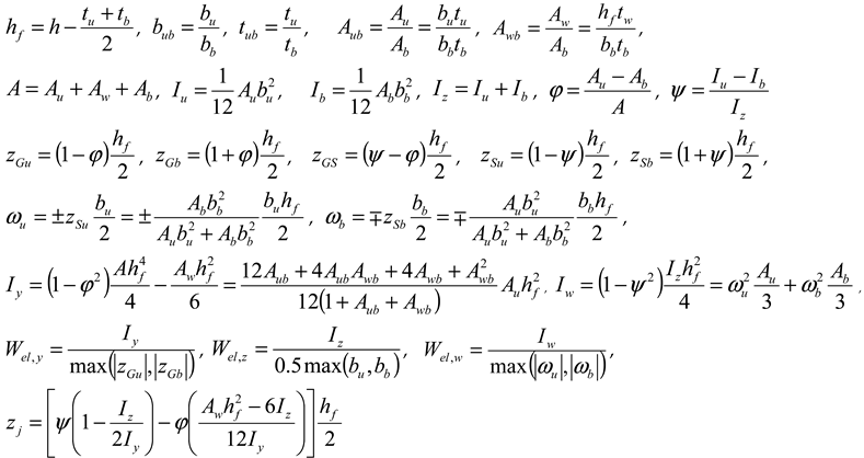
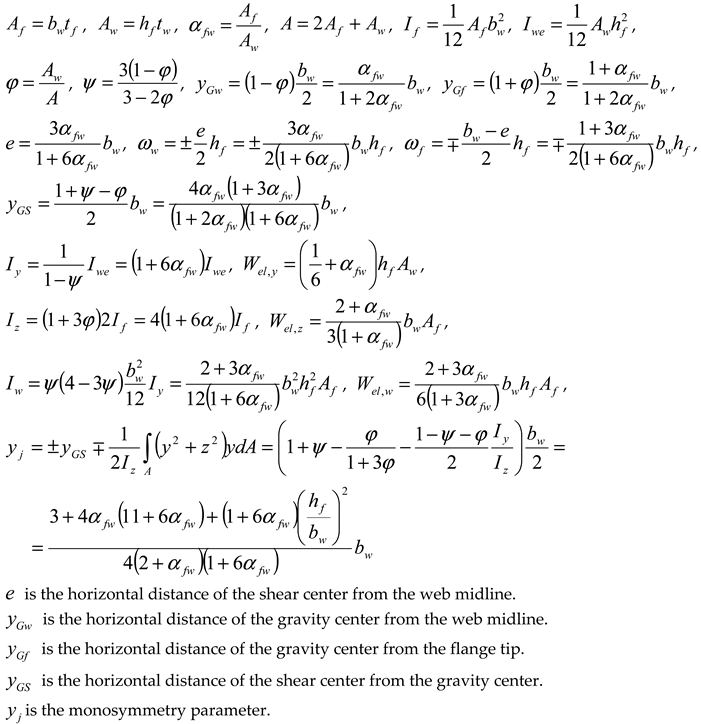
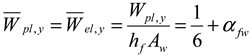
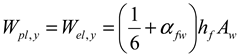
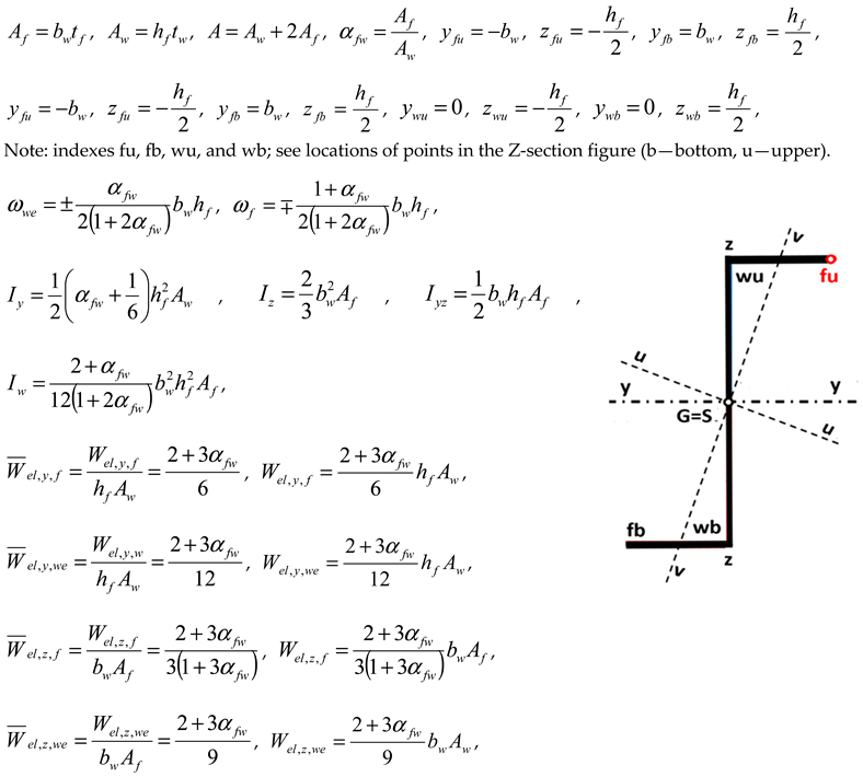 , , , , Note: indexes w—warping (except bw, ywu, ywb); we—web. atan, , , , , , , , , , | |
Disclaimer/Publisher’s Note: The statements, opinions and data contained in all publications are solely those of the individual author(s) and contributor(s) and not of MDPI and/or the editor(s). MDPI and/or the editor(s) disclaim responsibility for any injury to people or property resulting from any ideas, methods, instructions or products referred to in the content. |
© 2024 by the authors. Licensee MDPI, Basel, Switzerland. This article is an open access article distributed under the terms and conditions of the Creative Commons Attribution (CC BY) license (https://creativecommons.org/licenses/by/4.0/).
Share and Cite
Agüero, A.; Baláž, I.; Höglund, T.; Koleková, Y. Plastic Design of Metal Thin-Walled Cross-Sections of Any Shape Under Any Combination of Internal Forces. Buildings 2024, 14, 3890. https://doi.org/10.3390/buildings14123890
Agüero A, Baláž I, Höglund T, Koleková Y. Plastic Design of Metal Thin-Walled Cross-Sections of Any Shape Under Any Combination of Internal Forces. Buildings. 2024; 14(12):3890. https://doi.org/10.3390/buildings14123890
Chicago/Turabian StyleAgüero, Antonio, Ivan Baláž, Torsten Höglund, and Yvona Koleková. 2024. "Plastic Design of Metal Thin-Walled Cross-Sections of Any Shape Under Any Combination of Internal Forces" Buildings 14, no. 12: 3890. https://doi.org/10.3390/buildings14123890
APA StyleAgüero, A., Baláž, I., Höglund, T., & Koleková, Y. (2024). Plastic Design of Metal Thin-Walled Cross-Sections of Any Shape Under Any Combination of Internal Forces. Buildings, 14(12), 3890. https://doi.org/10.3390/buildings14123890