Article

Study on Mechanical Properties of Prefabricated Lattice Beam Joint

1
School of Civil Engineering and Transportation, South China University of Technology, Guangzhou 510641, China
2
Guangzhou Highway Engineering Group Co., Ltd., Guangzhou 510170, China
*
Author to whom correspondence should be addressed.
Buildings 2024, 14(12), 3781; https://doi.org/10.3390/buildings14123781
Submission received: 20 October 2024 / Revised: 14 November 2024 / Accepted: 18 November 2024 / Published: 27 November 2024

Abstract

The slope protection structure of the prefabricated lattice beam is one of the most widely used and studied systems in slope structure, with the connection between the lattice beam joint and the longitudinal and transverse beams being critical for structural performance and stability in engineering applications. Because the prefabricated structure is weak in its structural integrity, it is necessary to study the influence of prefabricated lattice beam joints and the longitudinal and transverse beams on the overall mechanical properties of the structure. In this paper, one ordinary cast-in-place concrete beam and six prefabricated beams with different joint-connection modes are designed, and the influence of different connection modes on the bending capacity of the beams is accordingly explored. Moreover, the flexural capacity, bending stiffness change, ductility, and energy absorption capacity of the beams are analyzed through three-point bending test. The test results show that the connection mode at the joints could significantly affect the overall mechanical properties of the structure. By embedding holes in steel sleeves, filling cement mortar in the middle, and using steel plates with a thickness of 16 mm for anchoring treatment joints of end plates, the specimen beams are thus obtained with the same flexural capacity, ductility, and energy absorption capacity as ordinary cast-in-place concrete beams. This study provides valuable insights into optimizing connection methods for prefabricated beams, which can lead to improved structural performance and wider adoption of prefabricated structures in the construction industry.

1. Introduction

Prefabricated concrete structures are widely used in building structures [1]. Compared with traditional cast-in-place structures, prefabricated concrete structures have many advantages, such as short construction periods, high production efficiency, low material consumption, high quality of finished products, low carbon, and environmental protection [2,3]. Therefore, prefabricated structures are one of the important ways for building-technology upgrading. However, currently, the structural integrity of the prefabricated structure is relatively weak [4,5]. This is because the on-site installation and construction quality of prefabricated component-connection joints is not easy to guarantee. Moreover, the narrow on-site installation and construction environment of prefabricated components and their excessive weight result in their having high requirements for construction equipment since, in this condition, it is difficult to align the joints with poor installation accuracy, which are the key influencing factors affecting the connection quality of joints [6].
The mechanical properties of component joints are the key to affecting the overall performance of the structure [7]. Therefore, in recent years, significant advancements have been made in prefabricated joint technology, including innovative connection methods and materials that enhance structural integrity [8,9]. Studies have explored new joint designs, like self-locking joints [10], grouted sleeves [11], and high-strength bolted connections [12], improving ease of assembly and load transfer efficiency. Additionally, emerging materials such as ultra-high-performance concrete [13], basalt fiber [14], and fiber-reinforced composites [15,16] have been applied to joint regions to enhance mechanical properties. Despite these advancements, there remain challenges in ensuring the structural integrity and performance of prefabricated structures, particularly in complex applications such as slope engineering.
In the process of slope engineering, disasters such as landslides are extremely susceptible to weather conditions, such as rainfall. In consequence, supporting while excavating is a core construction concept to avoid engineering accidents during the construction process [17,18]. Thus, prefabricated structures are widely used in slope support due to the advantages, such as a short construction period and high production efficiency [19,20]. Their application not only improves construction safety and efficiency but also minimizes environmental disruption, which is crucial in sensitive slope environments. The connection of prefabricated component beams in slope engineering is a key focus in the construction of prefabricated slope structures. Zheng Jing et al. [21] once proposed a prefabricated structure of a two-way variable cross-section beam to facilitate on-site assembly and determined the maximum tensile force that the structure can withstand through on-site tension-loading tests. The test results demonstrate that there are pores in the components during the actual assembly process and will lead to stress concentration if these pores are not filled. Such findings underscore the importance of rigorous quality control measures and the need for continuous monitoring of joint performance in critical applications [22]. Therefore, it is necessary to further study the influence of the connection method between slope joints and components on the overall performance of the structure.
However, there are few studies on the influence of the connection method between slope joints and components on the overall mechanical properties of the structure. Under this circumstance, based on the design principle of “strong joints and weak components” [23], it is a key point to find a suitable connection method for prefabricated lattice beam joints and the longitudinal and transverse beams to promote the application of prefabricated structures in slope engineering. In the past few decades, scholars from various countries have researched a lot on the performance of beam–column joints, such as the SCOPE [24], fiber-reinforced concrete beam–column joints [25], hybrid precast concrete beam–column joints [26], and sacrificial energy-dissipation beam–column joints [27]. Furthermore, Parastesh et al. [28] proposed ductile flexural joints that can be used in high-intensity areas. These connection methods have greatly promoted the development of prefabricated structures in buildings.
However, the applicability of prefabricated structures joints to slope engineering structures remains underexplored. To address this gap and enhance the structural performance of slope protection structures, the objective of this study is to investigate and develop effective connection methods between prefabricated slope joints and the longitudinal and transverse beams to enhance the structural performance of slope protection structures. By addressing the specific gaps in current research, this study contributes to the advancement of prefabricated slope protection technologies and promotes their wider application in engineering practice. In this paper, we conduct research on the connection methods between prefabricated slope joints and the longitudinal and transverse beams, propose several connection methods, and explore the influence of different connection methods on the flexural capacity of beams. The test studies and analyzes the flexural capacity, bending-stiffness change, ductility ratio, and energy absorption capacity of beams, providing valuable data for engineering applications.

2. Experimental Condition

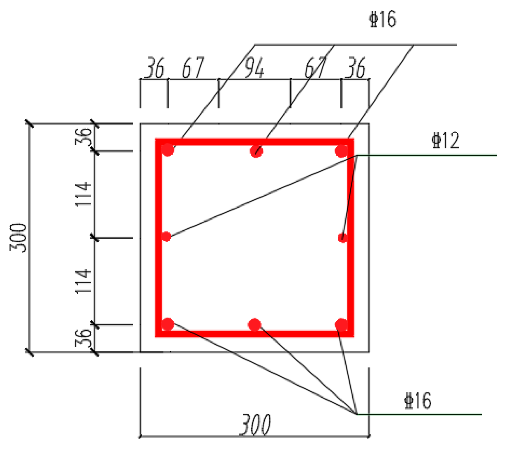
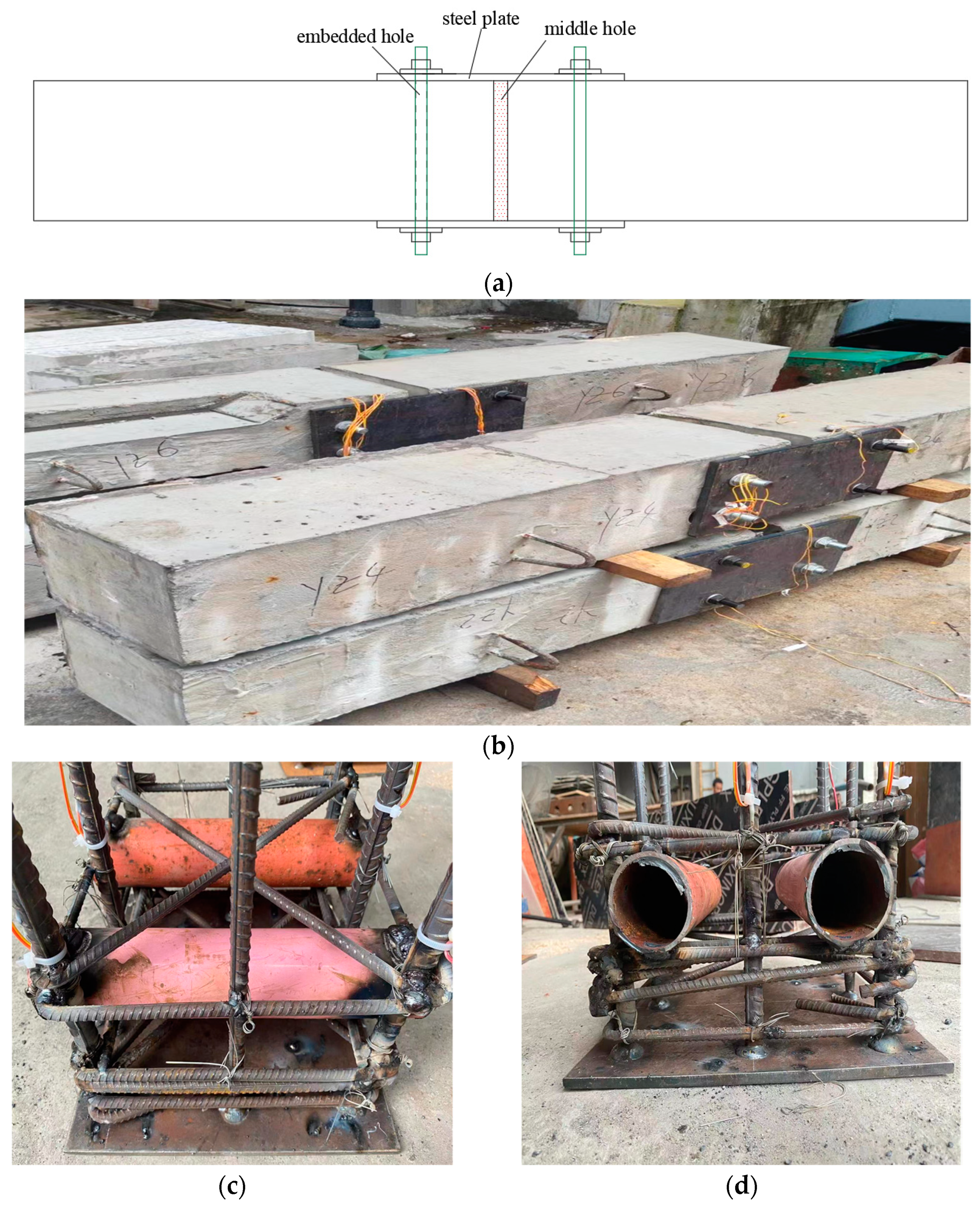
2.1. Specimen Design and Preparation
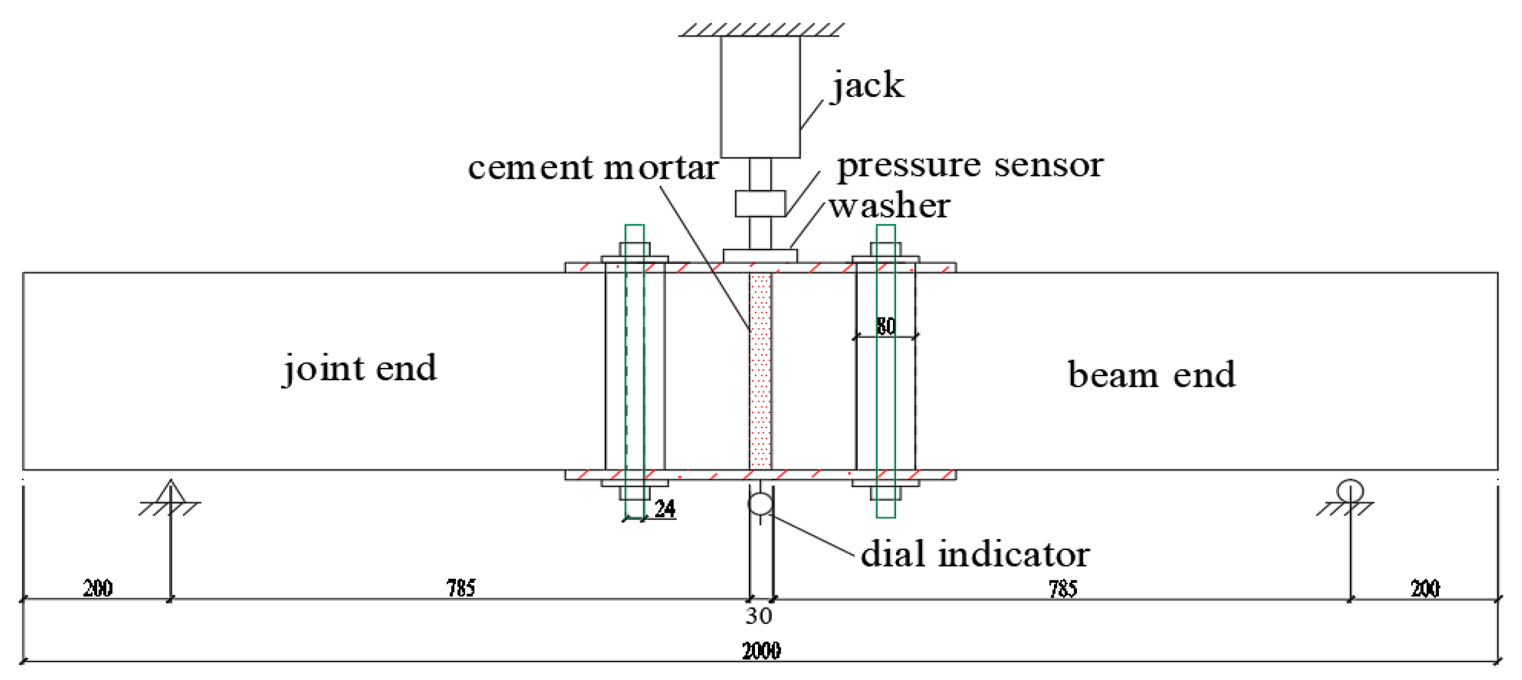
This paper tries to explore the influence of the connection method of lattice beam joints on the mechanical properties of beams. In this context, a total of seven specimens are designed for this test, with the size of 2000 mm × 300 mm × 300 mm. The specimen sizes were based on the typical dimensions of prefabricated lattice beams used in actual engineering projects, which enhances the practical applicability of our findings. Moreover, Specimen YZ1 is an ordinary cast-in-place concrete beam. The rest of the specimens are composed of two small beams, one simulating the on-site construction joint end, and the other simulating the longitudinal (transverse) beam end of the slope. The size of every small beam is 985 mm × 300 mm × 300 mm, and the main materials used for making the beams are all C25 concrete. The cement in the study is P.O 42.5-grade ordinary Portland cement. The connection methods of the test design specimens, which are commonly used in prefabricated construction, are shown in Table 1. The type of longitudinally stressed steel bars is HRB400, the stirrup steel bars are HPB300 steel bars, and the steel plate used to connect the beams is made of Q235 steel. The mechanical properties of the steel bar (plate) are shown in Table 2. The reinforcement of the beam and the specific connection are shown in Figure 1 and Figure 2, respectively. Among them, the thickness of the steel plate used in Specimen YZ5 is 14 mm, and the thickness of the steel plate used in Specimen YZ6 is 16 mm.

2.2. Loading Scheme

In the test, the specimens are loaded in a single-point mid-span loading mode with the 3000 kN electronic servo long-column pressure-testing machine in the Structural Laboratory of South China University of Technology. The size of the specimens and the layout of measuring points are shown in Figure 3.
In order to test the reliability and safety of the entire test device, the loading process is divided into preloading and formal loading. The preloading adopts hierarchical loading, with the maximum load up to 100 kN, and each level is loaded at 20 kN. After each stage, the load is held for 5 min to check any potential problems in the entire test system [29]. Moreover, when completing the preloading, the hierarchical unloading is accordingly performed.
The test carries out the official loading after completing the preloading. This official loading is still controlled by load and carried out at the step length of 20 kN. After each level, the load is held for 5 min, and then the corresponding data of each measuring point under the test load of this level are recorded. After loading to 100 kN, the loading step size is changed to 10 kN to better control the sudden occurrence of brittle failure, and at the same time, it is also conducive to carefully observing the development process of component failure. Throughout the loading process, the data-collection frequencies for both load and displacement remain once every 3 s.

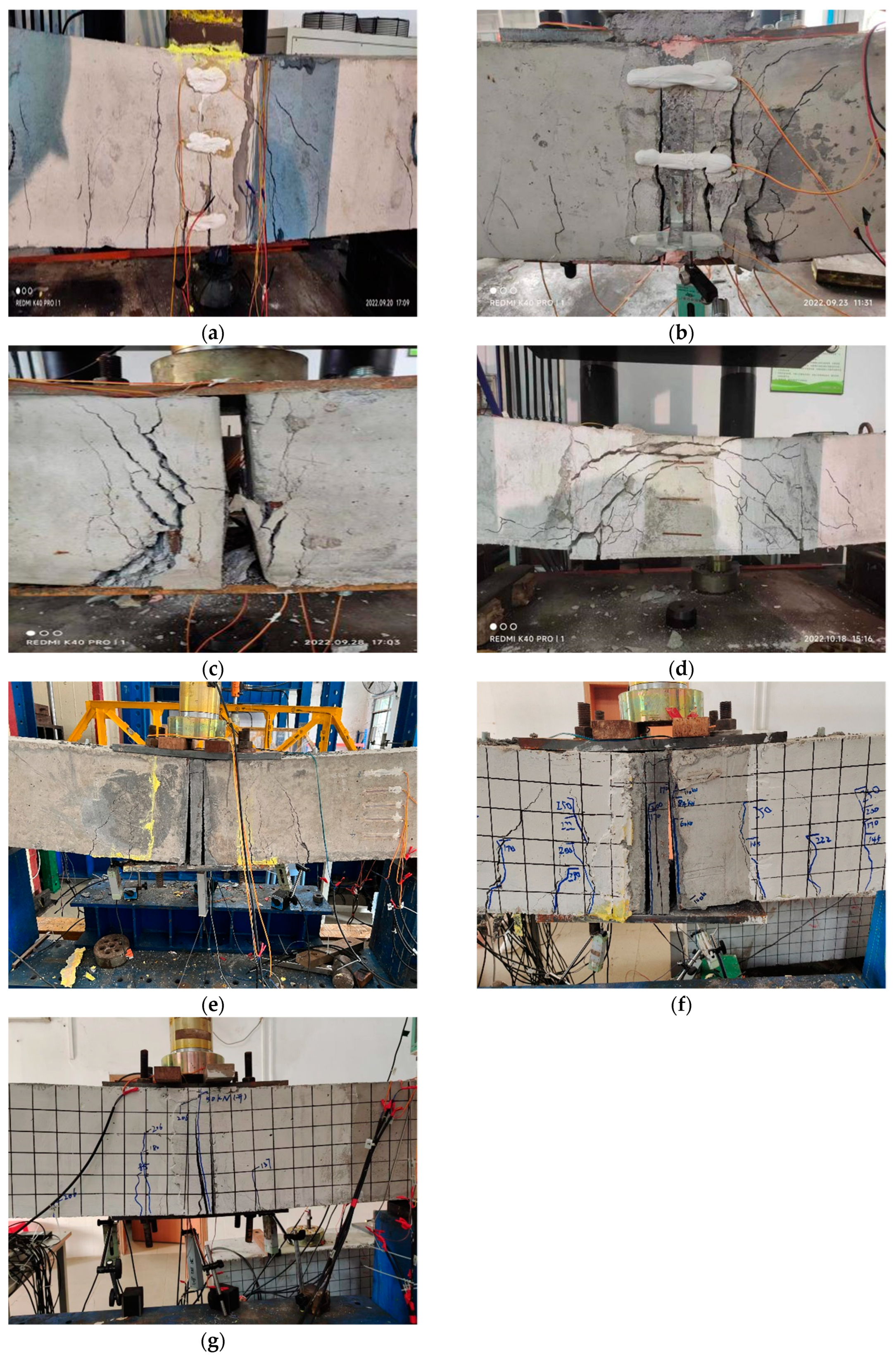
3. Experimental Phenomenon

During the entire loading process, the crack development and final failure mode of the beam are observed. When the load reaches about 160 kN, Specimen YZ1 first has 1–3 vertical cracks in the lower concrete in the area near the loading point. As the load increases, the vertical cracks continue to increase and extend along the height direction. As the loading continues, individual inclined cracks begin to appear at both ends of the beam, and the deflection of the beam increases significantly. Later, when the loading continues, the number of cracks at both ends of the beam increases, and the crack width becomes larger. Finally, Specimen YZ1 shows multiple vertical cracks originating from the mid-span, with signs of shear damage. The cracks extend outward and are indicative of flexural failure, with some fine cracks propagating toward the supports. The final failure modes of all specimens are shown in Figure 4 below. Compared with the ordinary concrete beam, Specimen YZ1, Specimen YZ2 demonstrates an earlier onset of cracking. When the load reaches 70 kN, Specimen YZ2 has cracks near the loading point. When it is finally damaged, Specimen YZ2 exhibits severe cracking at the mid-span, with a clear splitting pattern along the central axis. The cracks have widened significantly, indicating a progressive failure mechanism. There are visible fragments and spalling of the concrete at the loading point. In the whole process, the deflection rate of Specimen YZ3 with load increase is obviously greater than that of ordinary slow concrete beam Specimen YZ1, and its ultimate load is also much lower than that of Specimen YZ1. When Specimen YZ3 destroys, the central section is completely separated, with major cracks running vertically and along the diagonal. The extensive damage and splitting suggest a brittle failure mode. The concrete is fractured, and large sections are crumbled, showing extensive structural failure.
When Specimen YZ4 is subjected to load, the lower concrete at a certain distance from the loading point first has vertical cracks appear. Then, inclined cracks extending in the direction of the loading point appear on the two small beams of Specimen YZ4. Finally, the cracks on this specimen are widely distributed and extend from the mid-span to the supports. There are numerous diagonal and flexural cracks that converge, forming a complex fracture network. The failure is dominated by flexural cracking, with visible concrete crushing near the loading point. During loading, two obvious vertical cracks extending upward are generated at the interface between the two small beams and cement mortar of Specimen YZ5. Specimen YZ5 shows a prominent vertical crack at the mid-span, with additional diagonal cracks that suggest a combination of flexural and shear failure. The concrete near the mid-section fractures, and signs of crushing are present at the loading point. When Specimens YZ6 and YZ7 are subjected to load, obvious vertical cracks are generated at the interface between the small beam and cement mortar, and at the same time, several inclined cracks extending in the direction of the loading point appear in Specimen YZ6. Specimens YZ6 and YZ7 are marked with a grid, highlighting the locations and extent of cracks. The main crack of YZ6 runs vertically through the mid-span, with additional cracks branching out diagonally. The failure is primarily flexural. Specimen YZ7 shows a primary vertical crack at the mid-span and several diagonal cracks, suggesting combined flexural and shear failure.

4. Experimental Results and Analysis

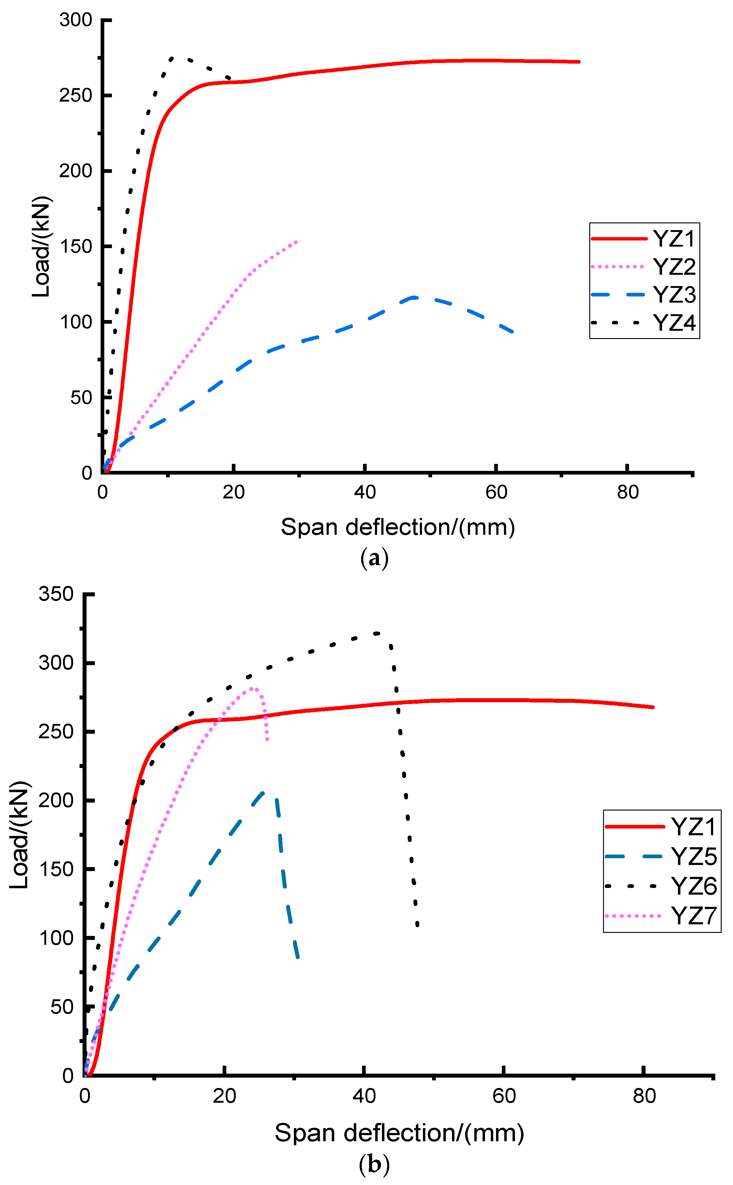
4.1. Analysis of Load–Deflection Curve

The load–deflection curve results of each specimen are shown in Figure 5. The load–deflection curves of all beam specimens can be regarded as approximately linear curves at the beginning. However, when the load increases, the concrete has the first crack, and the load–deflection curve begins to become nonlinear. Finally, as the load increases, the specimen is damaged, and the curve no longer rises.
The ultimate loads of each specimen and their corresponding mid-span deflections are shown in Table 3. It can be seen that different connection methods have great differences in the ultimate load of beams, indicating that the connection method at the joint has an impact on the overall mechanical properties of the structure. The ultimate load of Specimen YZ4 based on the lap connection method of steel bars is equivalent to that of the ordinary concrete beam, YZ1, but its deflection is much lower than that of the ordinary concrete beam, YZ1, demonstrating that Specimen YZ4 has low ductility, which will be discussed in detail later in this paper. Comparing the results of the ultimate bearing capacity of Specimens YZ3 and YZ3, it can be found that whether the joint pores are filled or not has a great influence on the ultimate load. The ultimate load without filling is reduced by 23.5% compared to that with filling, from 151 kN to 118 kN. The ultimate bearing capacity of Specimen YZ5 is 80% of that of the ordinary concrete beam. In addition, it can be seen that the ultimate loads of Specimens YZ6–YZ7 are slightly higher than the ultimate load of the ordinary concrete beam, YZ1, showing that the connection method of embedding holes in steel sleeves, filling with cement mortar in the middle, and anchoring end plates (U-shaped steel bars) has a better connection effect for joints and beams.

4.2. Average Bending Stiffness

In order to analyze the change in the flexural stiffness of the beam during loading, the average section stiffness, BS, is calculated by the following equation for analysis:
B s = F L 3 48 Δ
where F is the load, L is the beam length, and Δ is the deflection.
As shown in Table 4, the flexural stiffness of the specimen beams obtained through different connection methods varies greatly. When the specimen beams YZ2–YZ7 in this paper are damaged, their flexural stiffness is less than the initial flexural stiffness, which is consistent with that of the conventional concrete beam, Specimen YZ1. Compared with other specimens, the initial stiffness of Specimen YZ2 and Specimen YZ3 is quite small, which conforms to the observation in the experiment that the displacement increases with the load at a speed greater than that of the ordinary concrete beam, Specimen YZ1. In addition, when Specimen YZ2 and Specimen YZ3 are damaged, the bending stiffness does not change much compared with the initial flexural stiffness. This indicates that the failure of Specimens YZ2 and YZ3 at a lower load is likely due to brittle failure at the weak part of the connection, and the concrete has not reached its ultimate state. The initial flexural stiffness of Specimen YZ4 is greater than the flexural stiffness of ordinary concrete beams, and it still has a considerable flexural stiffness when it is damaged.
Furthermore, it can be observed from the table that the initial flexural stiffness of Specimen YZ6 is the largest, and the initial flexural stiffness of Specimen YZ5 is also higher than that of most specimens. This indicates that the initial flexural stiffness of the joint can be significantly improved through embedding holes in steel sleeves, filling with cement mortar in the middle, and anchoring the connection with end plates. What is more, the initial bending stiffness of Specimen YZ6 anchored with a 16 mm thick steel plate is significantly higher than that of Specimen YZ5 anchored with a 14 mm thick steel plate. This demonstrates that the stiffness of the steel plate used for end-plate anchoring has a great influence on the flexural stiffness of the joint section. For Specimen YZ6, treated by embedding holes in steel sleeves, filling with cement mortar in the middle, and anchoring with end plates from loading to failure, its flexural stiffness and that of the ordinary concrete beam, Specimen YZ1, both have a large change rate in this process, reaching more than 80%. In comparison, Specimen YZ7 has a relatively smaller reduction in stiffness during loading.

4.3. Displacement Ductility and Energy Absorption

Ductility is generally used to express a structure’s ability to resist inelastic behavior. The displacement ductility ratio is typically defined to characterize the ductility of structural elements. Based on the previous literature, there are various models for calculating the displacement ductility ratio. Usually, the Park model [30] is adopted to calculate the displacement ductility ratio. According to the model, the ductility ratio of displacement is expressed as the ratio of the displacement corresponding to the ultimate load (Δu) and the displacement corresponding to the equivalent elastic–plastic yield point (Δy) (as shown in Equation (2)). Here, the equivalent elastic–plastic yield point (Δy) corresponds to the displacement at the intersection of the tangent at the initial point of the load–displacement curve and the maximum point.
μ = Δ u Δ y
The displacement ductility ratio of each specimen is shown in Table 5. From the table, it can be seen that the ordinary concrete beam, Specimen YZ1, has the highest ductility, while Specimen YZ6 has ductility comparable to that of the ordinary concrete beam. The ductility of the other specimens is significantly lower than that of these two. This indicates that, in actual engineering, if the connections at the joints of prefabricated structures are not properly treated, the entire structure’s ability to resist non-elastic behavior at the joints will be significantly reduced, much lower than that of cast-in-place concrete beams. For example, the displacement ductility ratio of Specimens YZ2 and YZ3 is much lower than that of Specimen YZ1. In the existing literature [31], the minimum ductility ratio for ductile structural design is 3, while Specimens YZ2, YZ4, and YZ7 do not meet this standard. However, using steel sleeves with embedded holes, filling them with cement mortar, and anchoring end plates at the joints can ensure the ductility of the prefabricated concrete beams. For instance, the displacement ductility ratio of Specimen YZ6 is comparable to that of Specimen YZ1. The thickness of the steel plates used for anchoring the end plates affects the bending stiffness at the joints and, in turn, influences the ductility of the entire structure. For example, Specimens YZ6 and YZ5 used different steel-plate thicknesses and had different initial bending stiffnesses (as shown in Table 3), resulting in a twofold difference in their displacement ductility ratios (as shown in Table 4).
The energy absorption capacity of a beam can also be used to reflect its ability to resist inelastic deformation. The energy absorption capacity of the beam can be obtained by calculating the area under the force–displacement curve, which is the sum of the areas between two consecutive points (as shown in Equation (3)).
W = 0 . 5 i = 1 n 1 ( d i + 1 d i ) ( F i + 1 F i )
where di represents the displacement; Fi represents the load at this displacement (mm); n represents the number of displacement points.
The energy absorption ratio is defined as the ratio of the energy absorbed by the specimen beam to the energy absorbed by the ordinary concrete beam, Specimen YZ1, allowing for a comparison of the energy absorption capabilities of other specimen beams and ordinary cast-in-place concrete beams. The energy absorption capacities of each specimen are shown in Table 5, and it can be observed that the results are consistent with the previous analysis. From the data in Table 5, it can be seen that Specimen YZ6 has an energy absorption ratio of 0.97, which is nearly equivalent to the benchmark beam, YZ1. This indicates that YZ6 exhibits excellent resistance to inelastic behavior, possessing energy absorption capabilities similar to ordinary concrete beams. This suggests that the employed connection method effectively maintains the beam’s ductility and energy absorption performance. In contrast, Specimen YZ4 has the lowest energy absorption ratio of only 0.18, which may be due to its high bending stiffness, resulting in minimal noticeable deflection. When failure occurred under a load of 279 kN, its mid-span deflection was only 11 mm, indicating a weaker energy absorption performance.

4.4. Study Limitations and Future Research Prospects

Although this study explored different connection methods of prefabricated lattice beam joints and their influence on the mechanical properties of beams, yielding valuable insights, there are still limitations that need to be addressed. Firstly, due to experimental conditions and resource constraints, only one specimen was fabricated for each connection method, lacking parallel samples. This limitation prevents a statistical analysis, potentially affecting the reliability and generalizability of the results, and insufficiently revealing the variability in the experimental data. Secondly, there may be potential variability in material properties, such as the actual strength of the concrete and the mechanical properties of the steel bars, which could impact the test results but were not fully considered and quantified in this study. Additionally, the specimen sizes were relatively small, which may not comprehensively reflect the mechanical behavior of large-scale components in actual engineering applications.
Based on the aforementioned limitations, future research should focus on the following improvements and deepening. Firstly, increase the number of specimens by creating multiple parallel samples for each connection method, allowing for a statistical analysis to enhance the reliability and significance of the results. Secondly, consider the variability in material properties by conducting strict quality control and performance testing on materials like concrete and steel bars, or by using materials of different grades and types to evaluate their impact on the performance of connection methods. Moreover, it is recommended to conduct tests on larger specimens that simulate the dimensions of actual engineering components to more accurately reflect the performance of connection methods under real conditions. Finally, experiments under different environmental conditions (such as high temperatures, low temperatures, humidity variations, etc.) can be performed to study the effects of environmental factors on the performance of connection methods, providing more comprehensive guidance for engineering applications.

5. Conclusions

This paper explores the impact of different joint connection methods on the overall mechanical performance of beams. From our experiments and analysis of the beams, the following conclusions can be drawn:
(1)
This study investigates the mechanical properties of prefabricated beams with six different joint connection methods compared to cast-in-place ordinary concrete beams. The results indicate that the connection method significantly affects the overall mechanical performance of the beams. Specifically, the connection method influences the failure mode, ultimate load capacity, flexural stiffness, ductility, and energy absorption ratio of the beams.
(2)
Filling the joint pores or not has a considerable impact on the ultimate load. In the case of steel-plate bolt connections, the ultimate load of the specimens with unfilled voids is 23.5% lower than that of the specimens with filled pores.
(3)
For specimens with joints connected by overlapping steel bars, the ultimate load capacity is comparable to that of ordinary concrete beams; however, their displacement ductility coefficient is 1.97, which is significantly lower than that of cast-in-place ordinary concrete beams, and their energy absorption capacity is only 18% of that of the cast-in-place ordinary concrete beams.
(4)
By using a steel sleeve with embedded holes, filling them with cement mortar, and employing 16 mm thick steel plates for anchoring treatment nodes of end plates, the specimen beams exhibit a flexural capacity, ductility, and energy absorption capability comparable to that of cast-in-place ordinary concrete beams, which can be used for practical engineering applications.
The findings of this study can be applied to practical engineering projects to enhance the performance and reliability of prefabricated slope protection structures, especially in slope projects where reliability and safety are of paramount importance. However, it should be noted that the sample size in this study is limited, and there may be potential impacts due to variability in material properties. Therefore, future research should focus on increasing the number of specimens and considering variations in material properties to improve the reliability of the results.

Author Contributions

Conceptualization, Y.-G.F.; Investigation, Y.-L.K.; Data curation, W.H.; Writing—original draft, R.-G.G.; Writing—review & editing, Z.-X.Y., Y.-G.F. and Y.-F.X.; Project administration, R.-G.G.; Funding acquisition, Y.-G.F. All authors have read and agreed to the published version of the manuscript.

Funding

This research was funded by National Key Scientific Instruments and Equipment Development Projects of China, grant number 41827807.

Data Availability Statement

The original contributions presented in the study are included in the article, further inquiries can be directed to the corresponding author.

Conflicts of Interest

Authors Yong-Liang Kang, Wei Huang and Zong-Xue Yan were employed by the company Guangzhou Highway Engineering Group Co., Ltd. The remaining authors declare that the research was conducted in the absence of any commercial or financial relationships that could be construed as a potential conflict of interest.

References

  1. Yang, D.; Chen, J.; Wang, Z.; Guo, R.; Yu, Z. Flexural behaviour of precast reinforced concrete beams bonded to steel-reinforced engineered cementitious composites. Structures 2024, 66, 106834. [Google Scholar] [CrossRef]
  2. Shah, Y.I.; Hu, Z.; Yin, B.S.; Li, X. Flexural performance analysis of UHPC wet joint of prefabricated bridge deck. Arab. J. Sci. Eng. 2021, 46, 11253–11266. [Google Scholar] [CrossRef]
  3. Nie, X.; Liu, T. Experimental and Numerical Study on the Bending Behavior of Concrete-Concrete Composite Beams. China Civ. Eng. J. 2022, 55, 14–25. [Google Scholar]
  4. Huang, W.; Hu, G.; Miao, X.; Fan, Z. Seismic performance analysis of a novel demountable precast concrete beam-column connection with multi-slit devices. J. Build. Eng. 2021, 44, 102663. [Google Scholar] [CrossRef]
  5. Song, X.; Lian, Y. Research on the Connection Structure of Vertical Load-Bearing Component Joints in Prefabricated Concrete Buildings. Build. Struct. 2023, 53 (Suppl. S1), 1206–1210. [Google Scholar]
  6. Xing, Q. Mechanical Performance Study on the Joint of Concrete-Filled Steel Tube Columns and Steel-Concrete Composite Beams in Prefabricated Monolithic Underground Stations. Urban Rail Transit Res. 2023, 26, 59–65+70. [Google Scholar]
  7. Duanmu, X.; Xu, D.; Qiu, T.; Zou, Y. Bending behaviour of precast concrete segmental girders with steel rebars through epoxy joints. Structures 2024, 63, 106491. [Google Scholar] [CrossRef]
  8. Zheng, Y.; Guo, Z.; Guan, D.; Zhang, X. Parametric study on a novel grouted rolling pipe splice for precast concrete construction. Constr. Build. Mater. 2018, 166, 452–463. [Google Scholar] [CrossRef]
  9. Ghatrenabi, M.H.; Dabiryan, H.; Nosraty, H. Modeling the Geometry of Weft-knitted Integrated Preforms as Reinforcement of Composite Joints. Fibers Polym. 2021, 22, 2572–2580. [Google Scholar] [CrossRef]
  10. Dai, X.M.; Zong, L.; Ding, Y.; Zhang, H.W.; Shi, F.W. Seismic Behavior of Demountable Self-Lock Joint for Middle Column Connection in Modular Steel Construction. Buildings 2024, 14, 275. [Google Scholar] [CrossRef]
  11. Wang, T.; Zhou, Z.; Yuan, K.; Jiang, R.; Ma, X.; Li, L. Evaluation of common defects of grouted sleeve connectors. Case Stud. Constr. Mater. 2022, 17, e01605. [Google Scholar] [CrossRef]
  12. Guo, X.; Zhang, Y.; Xiong, Z.; Xiang, Y. Load-bearing capacity of occlusive high-strength bolt connections. J. Constr. Steel Res. 2016, 127, 1–14. [Google Scholar] [CrossRef]
  13. Ye, M.; Li, L.; Pei, B.; Yoo, D.Y.; Li, H.; Zhou, C. A critical review on shear performance of joints in precast Ultra-High-Performance Concrete (UHPC) segmental bridges. Eng. Struct. 2024, 301, 117224. [Google Scholar] [CrossRef]
  14. Sakthimurugan, K.; Baskar, K. Experimental investigation on rcc external beam-column joints retrofitted with basalt textile fabric under static loading. Compos. Struct. 2021, 268, 114001. [Google Scholar] [CrossRef]
  15. Tusnin, A.; Shchurov, E. The Structural Behaviour of Tension Steel Rods Strengthened with Carbon-Fiber-Reinforced Composite Materials. Buildings 2023, 13, 375. [Google Scholar] [CrossRef]
  16. Ren, F.M.; Tian, S.Y.; Gong, L.; Wu, J.L.; Mo, J.X.; Lai, C.L.; Lai, M.H. Seismic performance of a ring beam joint connecting FTCES column and RC/ESRC beam with NSC. J. Build. Eng. 2023, 63, 105366. [Google Scholar] [CrossRef]
  17. Gao, X.; Tian, W.P.; Li, J.; Qi, H.; Zhang, Z.; Li, S. Force and deformation response analysis of dual structure slope excavation and support. Geomat. Nat. Hazards Risk 2022, 13, 501–537. [Google Scholar] [CrossRef]
  18. Ding, Q.; Guo, C.; Liu, X.; Gong, X.; Zhou, W.; Ma, G. Multi-source monitoring data helps revealing and quantifying the excavation-induced deterioration of rock mass. Eng. Geol. 2023, 325, 107281. [Google Scholar] [CrossRef]
  19. Karamloo, M.; Afzali-Naniz, O.; Doostmohamadi, A. Impact of using different amounts of polyolefin macro fibers on fracture behavior, size effect, and mechanical properties of self-compacting lightweight concrete. Constr. Build. Mater. 2020, 250, 118856. [Google Scholar] [CrossRef]
  20. Guo, N.; Lu, F.; Yang, X.; Ma, T. Study on Bearing Characteristics and Calculation Method of Prefabricated Frame Prestressed Anchor Support Structure. Chin. J. Geotech. Eng. 2022, 44 (Suppl. S1), 254–258. [Google Scholar]
  21. Zheng, J.; An, M.; Su, J.; Zhen, Z. Field Experimental Study on Assembled Anchor (Cable) Frame. Railw. Constr. 2020, 60, 93–97. [Google Scholar]
  22. Li, H.; Lam, F.; Qiu, H. Comparison of glulam beam-to-beam connections with round dovetail and half-lap joints reinforced with self-tapping screws. Constr. Build. Mater. 2019, 227, 116437. [Google Scholar] [CrossRef]
  23. Peng, W.J.; Tao, M.X. Column-to-beam flexural strength ratio for rigorous strong-column–weak-beam design for steel–concrete composite frames. J. Build. Eng. 2024, 96, 110669. [Google Scholar] [CrossRef]
  24. Cai, J.; Feng, J.; Wang, Z.; Zhu, H. Research on Seismic Performance of Precast Prestressed Concrete Assembled Monolithic Frame. J. Sun Yat-Sen Univ. (Nat. Sci. Ed.) 2009, 48, 136–140. [Google Scholar]
  25. Liang, X.W.; Wang, Y.J.; Tao, Y.; Deng, M.K. Seismic performance of fiber-reinforced concrete interior beam-column joints. Eng. Struct. 2016, 126, 432–445. [Google Scholar] [CrossRef]
  26. Zhang, J.; Ding, C.; Rong, X.; Yang, H.; Li, Y. Development and experimental investigation of hybrid precast concrete beam–column joints. Eng. Struct. 2020, 219, 110922. [Google Scholar] [CrossRef]
  27. Lu, X.; Jin, X.; Tian, Y.; Xie, L.; Wang, Y. Experimental study and design methodology of sacrificial-energy dissipation beam-column joint. Eng. Struct. 2024, 314, 118263. [Google Scholar] [CrossRef]
  28. Parastesh, H.; Hajirasouliha, I.; Ramezani, R. A new ductile moment-resisting connection for precast concrete frames in seismic regions: An experimental investigation. Eng. Struct. 2014, 70, 144–157. [Google Scholar] [CrossRef]
  29. Fang, Y.; Xu, Y.; Gu, R. Experiment and analysis of mechanical properties of lightweight concrete prefabricated building structure beams. Int. J. Concr. Struct. Mater. 2022, 16, 5. [Google Scholar] [CrossRef]
  30. Gulec, A.; Kose, M.M.; Gogus, M.T. Experimental investigation of flexural performance of T-section prefabricated cage reinforced beams with self-compacting concrete. Structures 2021, 33, 2190–2197. [Google Scholar] [CrossRef]
  31. Sin, L.H.; Huan, W.T.; Islam, R.; Mansur, A. Reinforced Lightweight Concrete Beams in Flexure. ACI Struct. J. 2011, 108, 3–12. [Google Scholar]
Figure 1. Section reinforcement of beam. The red box indicates the stirrups.
Buildings 14 03781 g001
Figure 2. Connection of specimen joints. (a) Connection schematic diagram, (b) physical connection diagram, (c) connection method of YZ5-6, and (d) connection method of YZ7.
Buildings 14 03781 g002
Figure 3. Loading and measuring point arrangement.
Buildings 14 03781 g003
Figure 4. Failure pattern of the specimen: (a) YZ1, (b) YZ2, (c) YZ3, (d) YZ4, (e) YZ5, (f) YZ6, and (g) YZ7.
Buildings 14 03781 g004
Figure 5. Load–deflection curves: (a) load–deflection curve of YZ1–YZ5 and (b) load–deflection curves of YZ1 and YZ5–YZ7.
Buildings 14 03781 g005
Table 1. Experimental design of specimens.
No.Connection Method
YZ1Cast-in-place
YZ2Connect the steel plate with bolts and fill the middle gap with cement mortar
YZ3Connect the steel plate with bolts and do not fill the middle gap
YZ4Bar splicing
YZ5Embed hole for the steel sleeve, anchor the end plate, and fill the embedded hole and the middle gap with cement mortar
YZ6Embed hole for the steel sleeve, anchor the end plate, and fill the embedded hole and the middle gap with cement mortar
YZ7Embed hole for the steel sleeve, anchor the U bar, and fill the embedded hole and the middle gap with cement mortar
Table 2. Mechanical properties of the steel bar (plate).
Materialsfy (MPa)fu (MPa)Es (MPa)
HRB4004005402 × 105
HPB3003004202 × 105
Q2352354202 × 105
Note: The materials were sourced from Shaoguan Steel Group Company Limited, located in Guangdong Province, China.
Table 3. The ultimate load of the specimen and the corresponding mid-span deflection.
No.Ultimate Load/(kN)Deflection (mm)
YZ127372
YZ215128
YZ311848
YZ427911
YZ521927
YZ632542
YZ729125
Table 4. Bending stiffness of different specimens under failure.
No.Initial Flexural Stiffness/
(100 kN·m2)
Flexural Stiffness at Failure/
(100 kN·m2)
Change Rate
YZ124.784.8180.59%
YZ25.124.4113.87%
YZ33.052.1130.82%
YZ442.6421.6449.25%
YZ522.556.7470.11%
YZ643.726.4685.22%
YZ715.859.7738.40%
Table 5. The ductility and energy absorption ratio of the specimen.
No.Displacement Ductility Ratio, μEnergy Absorption Ratio
YZ17.681
YZ21.110.22
YZ31.450.28
YZ41.970.18
YZ53.250.30
YZ66.620.97
YZ71.590.40
Disclaimer/Publisher’s Note: The statements, opinions and data contained in all publications are solely those of the individual author(s) and contributor(s) and not of MDPI and/or the editor(s). MDPI and/or the editor(s) disclaim responsibility for any injury to people or property resulting from any ideas, methods, instructions or products referred to in the content.

