
Study on Engineering Properties and Mechanism of Loess Muck Grouting Materials

Abstract
1. Introduction
2. Experimental Program
2.1. Raw Materials
2.2. Mix Ratios and Preparation of LMGMs
2.3. Test Items
2.4. Performance Requirements
3. Results and Discussion
3.1. Fresh Properties
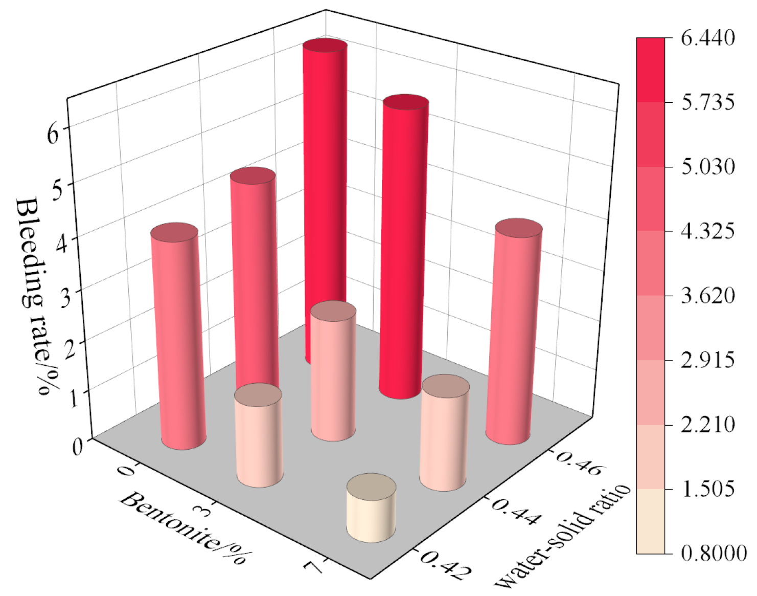
3.1.1. Bleeding Rate
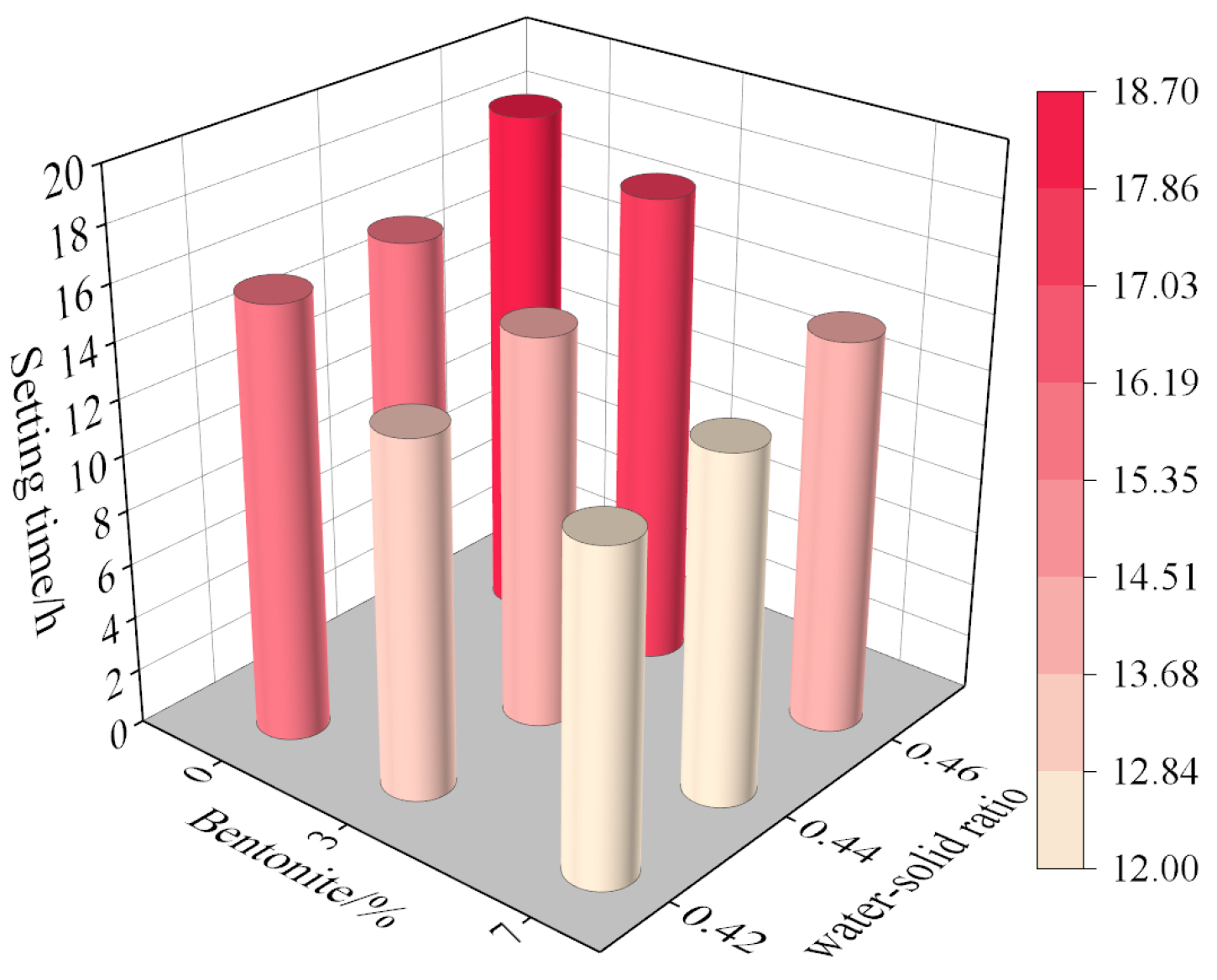
3.1.2. Setting Time
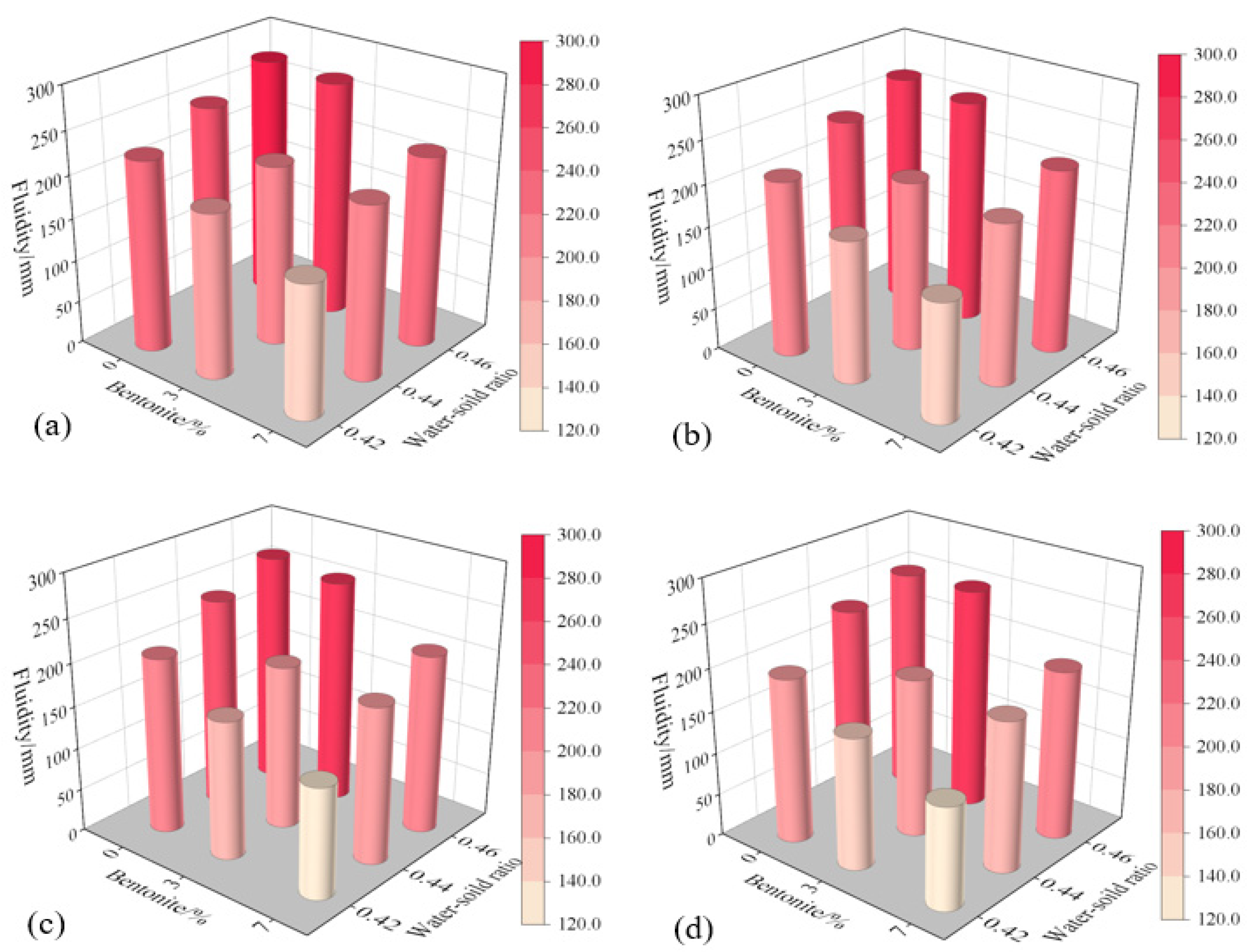
3.1.3. Fluidity
3.1.4. Consistency
3.2. Hardening Properties
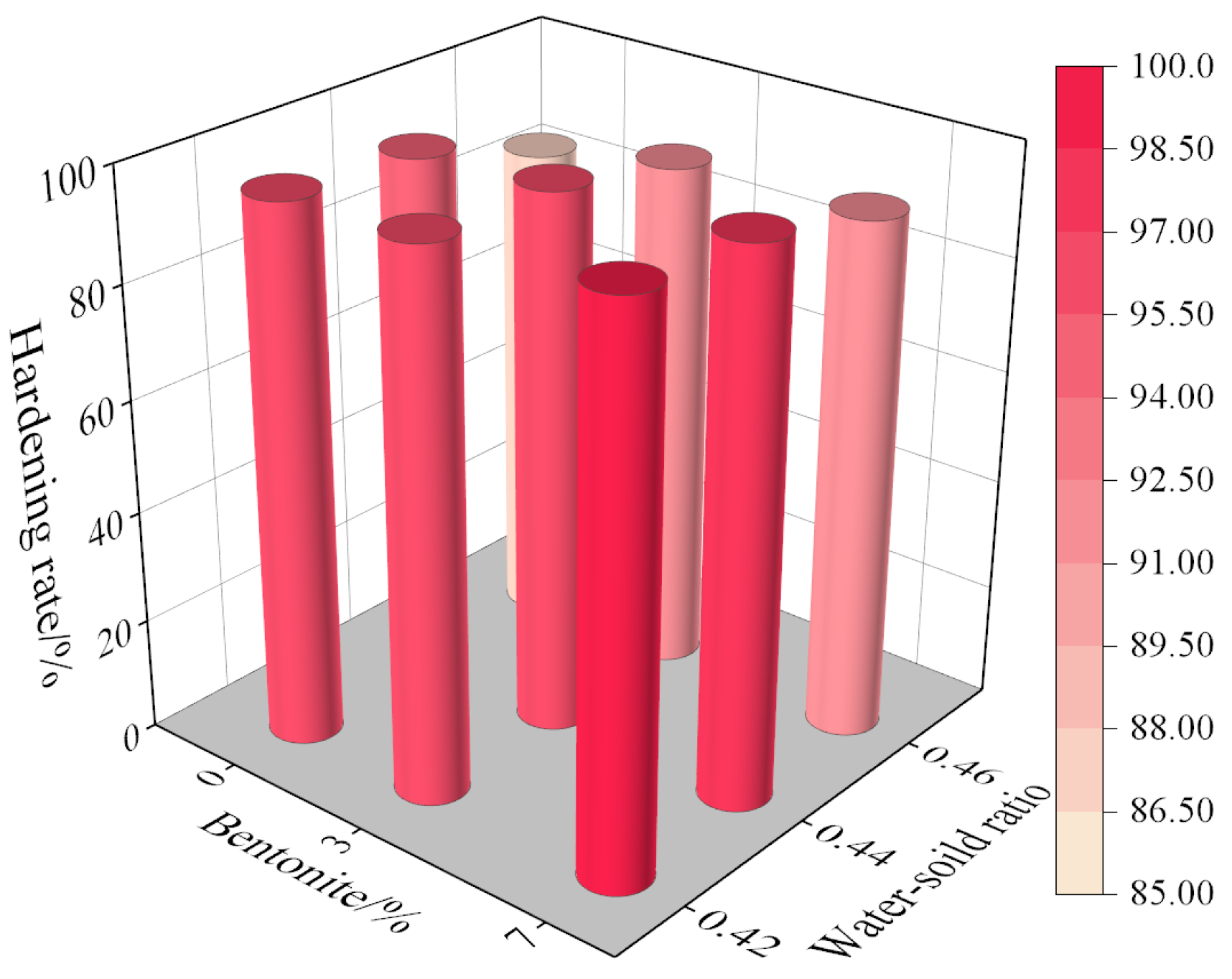
3.2.1. Hardening Rate
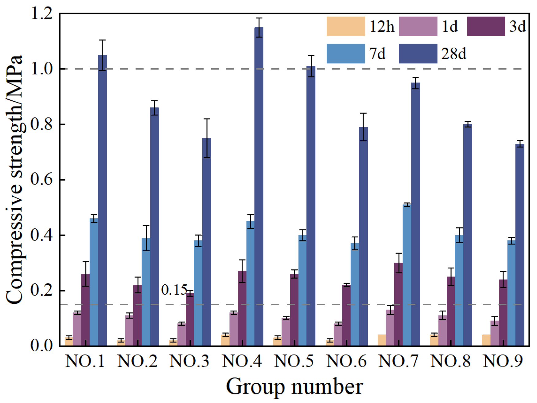
3.2.2. Compressive Strength
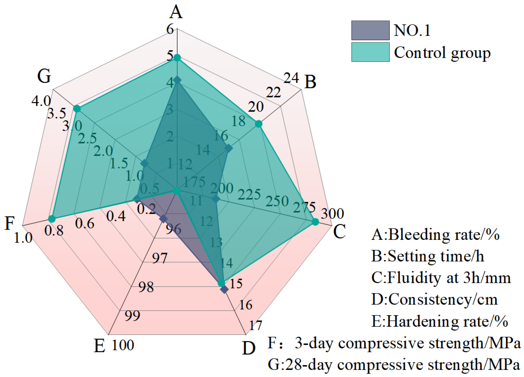
3.3. Comparative Analysis of Grouting Materials
3.4. Microstructure Characteristics
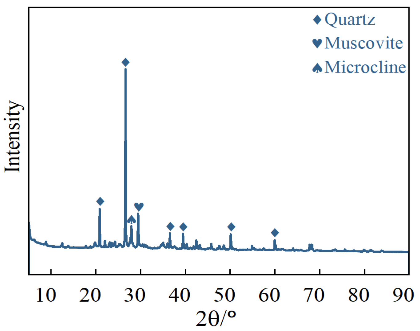
3.4.1. XRD
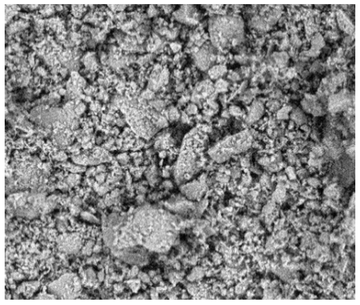
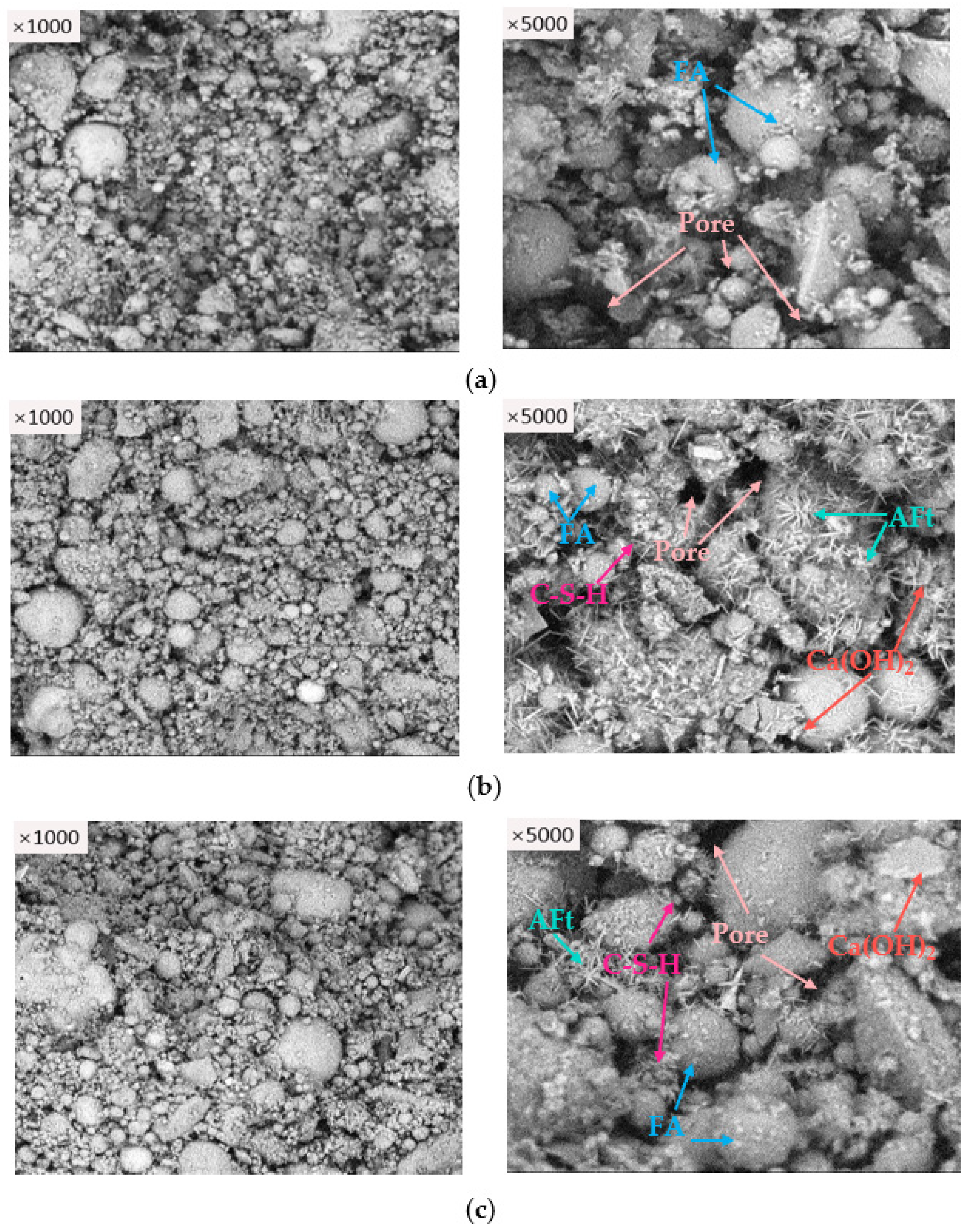
3.4.2. SEM
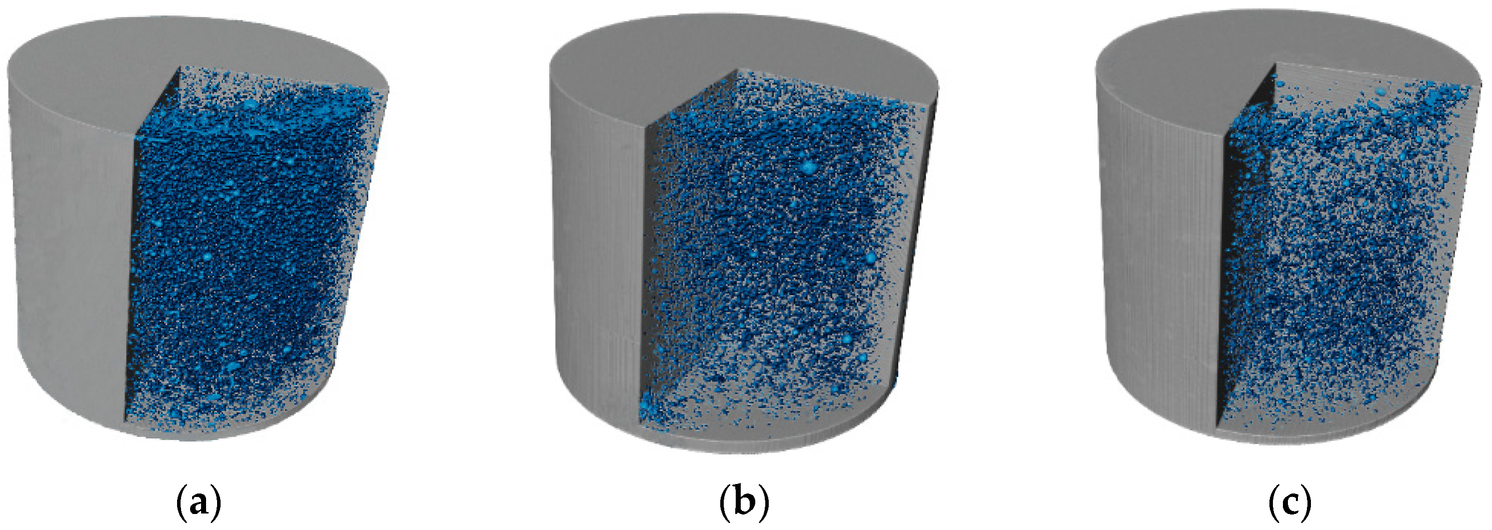
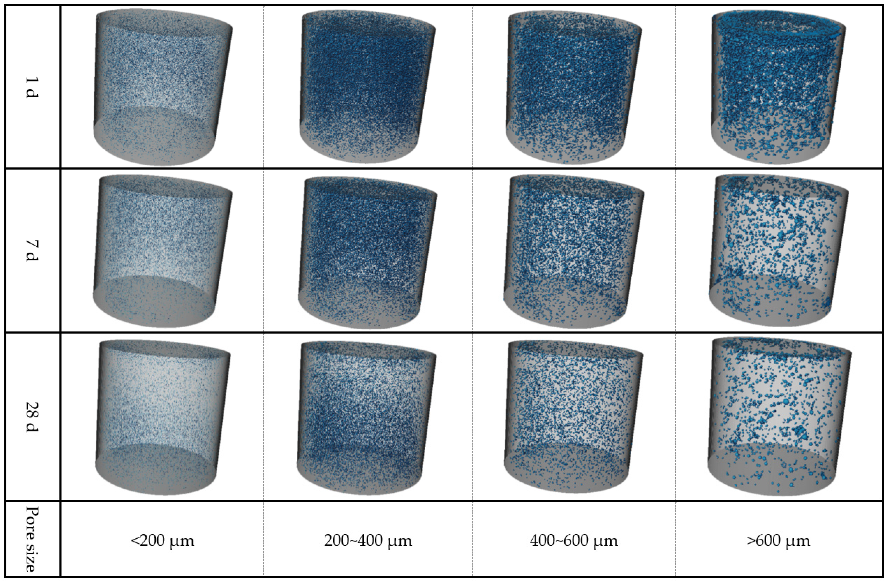
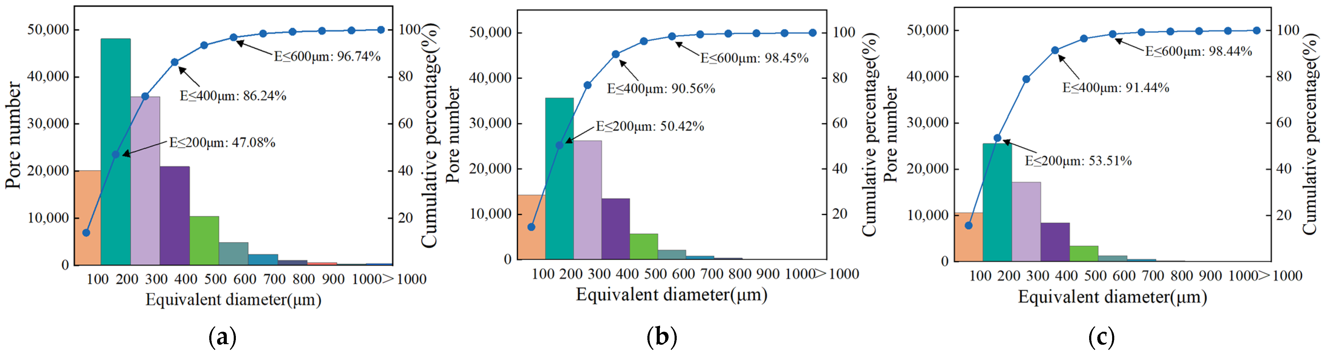
3.4.3. CT
4. Conclusions
- (1)
- The bleeding rate, setting time, fluidity, and consistency of LMGMs decreased by 36.24~79.95%, 20.63~24.05%, 19.61~30.67%, and 6.21~10%, respectively, as the bentonite content increased from 0% to 7%. Conversely, these parameters increased by 57.21~400%, 18.35~32.31%, 25.33~44.23%, and 12.5~15.83% as the water–solid ratio rose from 0.42 to 0.46. Additionally, the hardening rate of LMGMs increased by 5.59~9.9% with a higher bentonite content but decreased by 3.13~6.36% as the water–solid ratio increased.
- (2)
- The compressive strength of LMGMs initially increased and then decreased as the bentonite content increased, while it consistently decreased as the water–solid ratio rose. The compressive strength of LMGMs cured for 28 d reached 1.05 MPa, which was 855% higher than that of the tunnel surrounding rock.
- (3)
- The performance of NO.1 (10% for cement, 40% for fly ash, 50% for muck, and 0.42 for the water–solid ratio) meets on-site construction requirements. Compared to traditional grouting materials, NO.1 reduced costs by 49.46% and carbon emissions by 37.17%, demonstrating significant economic and environmental benefits.
- (4)
- As the curing time increased, gel filling and particle agglomeration reduced the number of pores in LMGMs, significantly enhancing the internal structure. The dense microstructure is the primary factor for the improvement in strength.
Author Contributions
Funding
Data Availability Statement
Conflicts of Interest
References
- Guo, S.; Wang, B.; Zhang, P.; Wang, S.; Guo, Z.; Hou, X. Influence analysis and relationship evolution between construction parameters and ground settlements induced by shield tunneling under soil-rock mixed-face conditions. Tunn. Undergr. Space Technol. 2023, 134, 105020. [Google Scholar] [CrossRef]
- Tang, C.; Shen, C.; Zhang, J.; Guo, Z. Identification of Safety Risk Factors in Metro Shield Construction. Buildings 2024, 14, 492. [Google Scholar] [CrossRef]
- Wang, X.; Zhao, W.; Wang, Z.; Wang, Z.; Sun, D.; Tang, X. Recycling the discharged soil from EPBS tunnels as a soil conditioner and its rheological behaviors. J. Clean. Prod. 2023, 418, 138224. [Google Scholar] [CrossRef]
- Zhang, J.; Lu, S.; Feng, T.; Yi, B.; Liu, J. Research on reuse of silty fine sand in backfill grouting material and optimization of backfill grouting material proportions. Tunn. Undergr. Space Technol. 2022, 130, 104751. [Google Scholar] [CrossRef]
- Carigi, A.; Saltarin, S.; Di Giovanni, A.; Todaro, C.; Peila, D. Reuse of EPB mucking for concrete production: A laboratory test campaign. Case Stud. Constr. Mater. 2023, 18, e02187. [Google Scholar] [CrossRef]
- Cao, W.; Zhao, J.; Jiang, Z.Y.; Li, Y.Z.; Che, C. Reuse of abandoned shield residues stabilized by a sustainable binder: Assessment of strength, durability, and environmental properties. Buildings 2023, 13, 738. [Google Scholar] [CrossRef]
- Taqa, A.; Al-Ansari, M.; Taha, R.; Senouci, A.; Al-Zubi, G.; Mohsen, M. Performance of concrete mixes containing TBM muck as partial coarse aggregate replacements. Materials 2021, 14, 6263. [Google Scholar] [CrossRef]
- Sharghi, M.; Jeong, H. The Potential of Recycling and Reusing Waste Materials in Underground Construction: A Review of Sustainable Practices and Challenges. Sustainability 2024, 16, 4889. [Google Scholar] [CrossRef]
- Hu, Y.; Yang, D.; Li, S.; Li, H.; Zhang, S.; Hou, Y.; Hu, W.; Zheng, H. Preliminary Study on Preparation of Unfired Bricks Using Filter Cake from Tunnel Muck. J. Build. Eng. 2022, 60, 105175. [Google Scholar] [CrossRef]
- Hong, J.; Chen, Z.; Huang, Y.; Cao, Y.; Geng, S.; Zhang, Y.; Zou, X.; Lu, X. Fabrication and Characterization of Lightweight Aggregate Prepared from Steel Mill Sludge in One Step. J. Mater. Cycles Waste Manag. 2022, 24, 1072–1082. [Google Scholar] [CrossRef]
- Jiao, N.; Wan, X.; Ding, J.; Zhang, X.; Xue, C. Mechanical Properties and Microstructure of Lime-Treated Shield Tunnel Muck Improved with Carbide Slag and Soda Residue. Constr. Build. Mater. 2024, 428, 136419. [Google Scholar] [CrossRef]
- Wang, J.; Fan, Y.; Xiong, X.; Zhao, F. Stabilization of Shield Muck Treated with Calcium Carbide Slag–Fly Ash. Buildings 2023, 13, 1707. [Google Scholar] [CrossRef]
- Guo, W.; Wang, B.; Li, Y.; Mo, S. Status Quo and Prospect of Harmless Disposal and Reclamation of Shield Muck in China. Tunn. Constr. 2020, 40, 1101. [Google Scholar]
- Wu, T.; Gao, Y.; Huang, C.; Jin, A.; Qu, X.; Ji, M.; Zhou, Y.; Li, J. In Situ Resource Reutilization of Earth Pressure Balance (EPB) Shield Muck for the Generation of Novel Synchronous Grouting Materials. Constr. Build. Mater. 2024, 421, 135737. [Google Scholar] [CrossRef]
- Murat, T.; Zhang, L.; Nehdi, M. Development of Sustainable Alkali-Activated Slag Grout for Preplaced Aggregate Concrete. J. Clean. Prod. 2020, 277, 123488. [Google Scholar] [CrossRef]
- Song, W.; Zha, F.; Zhu, Z.; Wang, F. Sulfate Resistance of Novel Alkali-Activated Filling Grout for Shield Tunnels: Comparison with Typical OPC-Based Filling Grout. J. Mater. Civ. Eng. 2023, 35, 04023472. [Google Scholar] [CrossRef]
- Roumeliotis, S.; Lampropoulos, K.; Delegou, E.; Tsilimantou, E.; Keramidas, V.; Bakolas, A.; Moropoulou, A. Enhanced Documentation and Evaluation of Grouting Process, through the Fusion of Non-Destructive Testing and Evaluation Information—The Case Study of the Katholikon of the Monastery of Panagia Varnakova. Buildings 2024, 14, 814. [Google Scholar] [CrossRef]
- Zeng, L.; Zhang, X.; Xie, X.; Zhou, B.; Xu, C.; Lambot, S. Measuring Annular Thickness of Backfill Grouting Behind Shield Tunnel Lining Based on GPR Monitoring and Data Mining. Autom. Constr. 2023, 150, 104811. [Google Scholar] [CrossRef]
- Luo, G.; Xiao, C.; Liu, Y.; Feng, K.; Ren, Q. Research on the Reuse of Discharged Soil from EBP Shield Tunnels in Synchronous Grouting Material. Adv. Civ. Eng. 2022, 2022, 8102488. [Google Scholar] [CrossRef]
- Miltiadou-Fezans, A.; Kalagri, A.; Anagnostopoulou, S. Design and Application of Mortars and Grouts for the Restoration of the Byzantine Church of Panaghia Krena in Chios Island, Greece. Buildings 2024, 14, 2542. [Google Scholar] [CrossRef]
- Zhang, C.; Yang, J.; Fu, J.; Wang, S.; Yin, J.; Xie, Y. Recycling of Discharged Soil from EPB Shield Tunnels as a Sustainable Raw Material for Synchronous Grouting. J. Clean. Prod. 2020, 268, 121947. [Google Scholar] [CrossRef]
- Zhou, S.; Li, X.; Ji, C.; Xiao, J. Back-Fill Grout Experimental Test for Discharged Soils Reuse of the Large-Diameter Size Slurry Shield Tunnel. KSCE J. Civ. Eng. 2017, 21, 725–733. [Google Scholar] [CrossRef]
- Cui, Y.; Tan, Z.; Wang, J.; Shi, Y.; Bai, Z.; Cao, Y. Research on Reuse of Shield Soil Dregs on Synchronous Grouting Materials and Its Application. Constr. Build. Mater. 2023, 408, 133700. [Google Scholar] [CrossRef]
- Ni, Z.; Wang, S.; Zheng, X.; Qi, C. Application of Geopolymer in Synchronous Grouting for Reusing of the Shield Muck in Silty Clay Layer. Constr. Build. Mater. 2024, 419, 135345. [Google Scholar] [CrossRef]
- GB/T 50123-2019; Standard for Geotechnical Testing Method. Ministry of Housing and Urban-Rural Development: Beijing, China, 2019.
- T/CECS 563-2018; Technical Specification for Simultaneous Grouting Material in Shield Projects. China Association for Engineering Construction Standardization: Beijing, China, 2018.
- JGJ/T 70-2009; Standard for Test Method of Basic Properties of Construction Mortar. Ministry of Housing and Urban-Rural Development: Beijing, China, 2009.
- GB/T 50448-2015; Technical Code for Application of Cementitious Grout. Ministry of Housing and Urban-Rural Development: Beijing, China, 2015.
- JTG E51-2009; Test Methods of Materials Stabilized with Inorganic Binders for Highway Engineering. Ministry of Transport of the People’s Republic of China: Beijing, China, 2009.
- Song, W.; Zhu, Z.; Pu, S.; Wan, Y.; Huo, W.; Peng, Y. Preparation and Engineering Properties of Alkali-Activated Filling Grouts for Shield Tunnel. Constr. Build. Mater. 2022, 314, 125620. [Google Scholar] [CrossRef]
- Li, Z.; Gao, Y.; Zhang, M.; Zhang, C.; Zhang, J.; Wang, C.; Zhang, N. The Enhancement Effect of Ca-Bentonite on the Working Performance of Red Mud-Slag Based Geopolymeric Grout. Mater. Chem. Phys. 2022, 276, 125311. [Google Scholar] [CrossRef]
- Yin, S.; Zhou, Y.; Wang, L.; Pan, J.; Kou, Y. Setting, Bleeding, and Hardening Strength Properties of Coarse Aggregate Backfill Slurry. Case Stud. Constr. Mater. 2022, 17, e01667. [Google Scholar] [CrossRef]
- Todaro, C.; Pace, F. Elastic Properties of Two-Component Grouts at Short Curing Times: The Role of Bentonite. Tunn. Undergr. Space Technol. 2022, 130, 104756. [Google Scholar] [CrossRef]
- Burris, L.; Kurtis, K. Water-to-Cement Ratio of Calcium Sulfoaluminate Belite Cements: Hydration, Setting Time, and Strength Development. Cement 2022, 8, 100032. [Google Scholar] [CrossRef]
- Sha, F.; Fan, R.; Gu, S.; Xi, M. Strengthening Effect of Sulphoaluminate Cementitious Grouting Material for Water-Bearing Broken Rocky Stratum. Constr. Build. Mater. 2023, 368, 130390. [Google Scholar] [CrossRef]
- Abdalqader, A.; Fayyad, T.; Sonebi, M. Optimization of Fresh Properties, Rheological Parameters and Mechanical Performances of Grouts Containing Bentonite. Mater. Today Proc. 2023, 2214–7853. [Google Scholar] [CrossRef]
- Zheng, G.; Huang, J.; Diao, Y.; Ma, A.; Su, Y.; Chen, H. Formulation and Performance of Slow-Setting Cement-Based Grouting Paste (SCGP) for Capsule Grouting Technology Using Orthogonal Test. Constr. Build. Mater. 2021, 302, 124204. [Google Scholar] [CrossRef]
- Li, W.; Zhang, Q.; Li, L.; Li, Y.; Zhang, H.; Lu, L. Investigation on Water and Fertilizer Retention Properties of Hydrated Sulphoaluminate Cement Pastes Modified by Bentonite for Porous Ecological Concrete. Case Stud. Constr. Mater. 2023, 18, e01967. [Google Scholar] [CrossRef]
- Xu, J.; Xiao, C.; Wu, H.; Kang, X. Reuse of Excavated Clayey Silt in Cement–Fly Ash–Bentonite Hybrid Back-Fill Grouting During Shield Tunneling. Sustainability 2020, 12, 1017. [Google Scholar] [CrossRef]
- Huynh, P.T.; Ogawa, Y.; Kawai, K.; Bui, P.T. Effect of Cement Type and Water-to-Binder Ratio on k-Value of Low-Calcium Fly Ash for Concrete Compressive Strength. J. Mater. Civ. Eng. 2023, 35, 04023427. [Google Scholar] [CrossRef]
- Rudić, O.; Ukrainczyk, N.; Krüger, M.; Tritthart, J.; Juhart, J. Efficiency of Limestone in Clinker-Reduced Binders: Consideration of Water-Binder Ratio, Capillary Porosity and Compressive Strength. Constr. Build. Mater. 2023, 386, 131594. [Google Scholar] [CrossRef]
- Nag, M.; Labira, D.; Shimaoka, T.; Nakayama, H.; Komiya, T. Utilization of Size-Fractionated Pozzolanic Bottom Ash to Immobilize Heavy Metals in MSW Incinerator Fly Ash. J. Environ. Chem. Eng. 2023, 11, 110394. [Google Scholar] [CrossRef]
- Ran, B.; Omikrine-Metalssi, O.; Fen-Chong, T.; Dangla, P.; Li, K. Pore Crystallization and Expansion of Cement Pastes in Sulfate Solutions with and Without Chlorides. Cem. Concr. Res. 2023, 166, 107099. [Google Scholar] [CrossRef]
- Rocha, J.; Filho, R. Microstructure, Hydration Process, and Compressive Strength Assessment of Ternary Mixtures Containing Portland Cement, Recycled Concrete Powder, and Metakaolin. J. Clean. Prod. 2024, 434, 140085. [Google Scholar] [CrossRef]
- Ma, X.; He, T.; Xu, Y.; Yang, R.; Sun, Y. Hydration Reaction and Compressive Strength of Small Amount of Silica Fume on Cement-Fly Ash Matrix. Case Stud. Constr. Mater. 2022, 16, e00989. [Google Scholar] [CrossRef]
- Du, S.; Zhang, Y.; Zhang, J.; Selyutina, N.; Smirnov, I.; Ma, G.; Zhang, X.; Li, B.; Miao, Y.; Liu, Y.; et al. Study on Pore Characteristics of Recycled Aggregate Concrete Mixed with Glazed Hollow Beads at High Temperatures Based on 3-D Reconstruction of Computed Tomography Images. Constr. Build. Mater. 2022, 323, 126564. [Google Scholar] [CrossRef]
- Song, W.; Zhu, Z.; Pu, S.; Wan, Y.; Huo, W.; Song, S.; Zhang, J.; Yao, K.; Hu, L. Efficient Use of Steel Slag in Alkali-Activated Fly Ash-Steel Slag-Ground Granulated Blast Furnace Slag Ternary Blends. Constr. Build. Mater. 2020, 259, 119814. [Google Scholar] [CrossRef]


| Material | SiO2 | CaO | Al2O3 | Fe2O3 | MgO | K2O | SO3 |
|---|---|---|---|---|---|---|---|
| Cement | 21.45% | 65.72% | 5.64% | 4.17% | 1.12% | 0.35% | 1.34% |
| Fly ash | 40% | 10% | 30% | 4.20% | 2.50% | 1.10% | 2.42% |
| PH | Expansion Index (mL/2 g) | Expansion Capacity (mL/g) | Colloid Number (mL/15 g) | 2 h Water Absorption (%) | Moisture Content (%) | Granularity (%) |
|---|---|---|---|---|---|---|
| 9~9.5 | 20~22 | ≥50 | ≥400 | 200~250 | ≤12 | Pass 200-mesh ≥ 95% |
| Control Group | Cement/% | Fly Ash/% | Bentonite/% | Sand/% | Water/Solid Ratio |
|---|---|---|---|---|---|
| 13 | 22 | 7 | 58 | 0.33 |
| NO. | Cement/% | Fly Ash/% | Muck/% | Bentonite/% | Water/Solid Ratio |
|---|---|---|---|---|---|
| 1 | 10 | 40 | 50 | 0 | 0.42 |
| 2 | 10 | 40 | 50 | 0 | 0.44 |
| 3 | 10 | 40 | 50 | 0 | 0.46 |
| 4 | 10 | 40 | 50 | 3 | 0.42 |
| 5 | 10 | 40 | 50 | 3 | 0.44 |
| 6 | 10 | 40 | 50 | 3 | 0.46 |
| 7 | 10 | 40 | 50 | 7 | 0.42 |
| 8 | 10 | 40 | 50 | 7 | 0.44 |
| 9 | 10 | 40 | 50 | 7 | 0.46 |
| Item | Bleeding Rate/% | Setting Time/h | Fluidity /mm | Consistency /cm | Hardening Rate/% | Compressive Strength/MPa | |
|---|---|---|---|---|---|---|---|
| 3/d | 28/d | ||||||
| Requirements | <5 | 10~24 | >160 | 11–16 | >95 | 0.15 | 1 |
| NO. | Bleeding Rate/% | Hardening Rate/% | Setting Time/h | Fluidity/mm | Consistency/cm | Compressive Strength/MPa | |
|---|---|---|---|---|---|---|---|
| 3 d | 28 d | ||||||
| NO.1 | 4.09 | 96 | 15.8 | 195 | 14.8 | 0.22 | 1.05 |
| NO.5 | 2.44 | 96 | 13 | 188 | 13.6 | 0.22 | 1 |
| Variable | Expression | R2 | p |
|---|---|---|---|
| fbleeding rate | −31.131 − 38.6X1 + 81.667X2 | 0.896 | 0.001 |
| fsetting time | −17.768 − 54.279X1 + 78.333X2 | 0.929 | <0.001 |
| f3-h fluidity | −671.216 − 930.18X1 + 2050X2 | 0.939 | <0.001 |
| fhardening rate | 172.869 + 53.919X1 − 182.5X2 | 0.852 | 0.003 |
| f3-d strength | 0.887 + 0.559X1 − 1.5X2 | 0.915 | <0.001 |
| f28-d strength | 4.16 − 1.023X1 − 7.333X2 | 0.815 | 0.01 |
| Main Projects | Price Comparison | Carbon Emission Comparison | ||||
|---|---|---|---|---|---|---|
| Market Price | Traditional Grouting Materials (m3) | NO.1 (m3) | Carbon Emission | Traditional Grouting Materials (m3) | NO.1 (m3) | |
| Cement | 380 RMB/t | 180 kg | 121.8 kg | 94 0 kg/t | 180 kg | 121.8 kg |
| Fly ash | 175 RMB/t | 320 kg | 487.3 kg | — | 320 kg | 487.3 kg |
| River sand | 120 RMB/t | 800 kg | — | 5 kg/t | 800 kg | 0 |
| Bentonite | 400 RMB/t | 100 kg | — | 41 kg/t | 100 kg | 0 |
| Shield muck | — | — | 609.2 kg | −5.07 kg/t | — | 609.2 kg |
| Total | 260.4 RMB | 131.6 RMB | 177.3 kg | 111.4 kg | ||
| Savings | 128.8 RMB | 65.9 kg | ||||
| Group Number | Cost /RMB | Bleeding Rate/% | Hardening Rate/% | Setting Time/h | Fluidity /mm | Consistency /cm | Compressive Strength/MPa | |
|---|---|---|---|---|---|---|---|---|
| 3 d | 28 d | |||||||
| NO.1 | 131.6 | 4.09 | 96 | 15.8 | 195 | 14.8 | 0.22 | 1.05 |
| high-performance grouting materials | 429.7 | 2.2 | — | 7.25 | 337 | — | 4.95 | 16.44 |
Disclaimer/Publisher’s Note: The statements, opinions and data contained in all publications are solely those of the individual author(s) and contributor(s) and not of MDPI and/or the editor(s). MDPI and/or the editor(s) disclaim responsibility for any injury to people or property resulting from any ideas, methods, instructions or products referred to in the content. |
© 2024 by the authors. Licensee MDPI, Basel, Switzerland. This article is an open access article distributed under the terms and conditions of the Creative Commons Attribution (CC BY) license (https://creativecommons.org/licenses/by/4.0/).
Share and Cite
Wu, Z.; Ye, C.; He, B.; Cao, F.; Zhang, T. Study on Engineering Properties and Mechanism of Loess Muck Grouting Materials. Buildings 2024, 14, 3400. https://doi.org/10.3390/buildings14113400
Wu Z, Ye C, He B, Cao F, Zhang T. Study on Engineering Properties and Mechanism of Loess Muck Grouting Materials. Buildings. 2024; 14(11):3400. https://doi.org/10.3390/buildings14113400
Chicago/Turabian StyleWu, Zhenxu, Chaoliang Ye, Benguo He, Fengxu Cao, and Tao Zhang. 2024. "Study on Engineering Properties and Mechanism of Loess Muck Grouting Materials" Buildings 14, no. 11: 3400. https://doi.org/10.3390/buildings14113400
APA StyleWu, Z., Ye, C., He, B., Cao, F., & Zhang, T. (2024). Study on Engineering Properties and Mechanism of Loess Muck Grouting Materials. Buildings, 14(11), 3400. https://doi.org/10.3390/buildings14113400