Article

On-Site Measuring Robot Technology for Post-Construction Quality Assessment of Building Projects

1
China Construction Eighth Engineering Division Co., Ltd., Shanghai 200112, China
2
Key Lab of Structures Dynamic Behavior and Control of the Ministry of Education, Harbin Institute of Technology, Harbin 150090, China
*
Authors to whom correspondence should be addressed.
These authors contributed equally to this work.
Buildings 2024, 14(10), 3085; https://doi.org/10.3390/buildings14103085
Submission received: 16 August 2024 / Revised: 18 September 2024 / Accepted: 23 September 2024 / Published: 26 September 2024
(This article belongs to the Special Issue Advances and Applications in Structural Vibration Control)

Abstract

:
Post-construction quality assessment of building projects involves inspecting and verifying that completed construction works meet the specified standards. This process is traditionally conducted through manual methods, which can be inefficient and time-consuming. Existing measurement robots, typically integrating a robotic platform with 3D laser scanners, face challenges such as high storage demands, reliance on specialized post-processing software, and substantial costs. Additionally, robots with multiple sensors may face limitations in handling diverse measurement items. To address these issues, this article introduces a cost-effective and fully automated on-site measuring robot. A systematic approach was employed, including robot design, measurement algorithm development, validation experiments, and engineering applications. Firstly, a cost-effective hardware was designed, reducing expenses by 30% compared to commercial 3D laser scanners. Thereafter, the algorithm was developed by processing effective point cloud data to measure dimensions, wall evenness, alignments, floor heights, and corner angles, achieving a 90% reduction in data storage requirements. Subsequently, validation experiments were conducted, which verified the measurement accuracy of the developed robot. Furthermore, the robot was applied in two building projects, demonstrating a 40% improvement in efficiency over manual measurements and a minimum 50% reduction in labor costs. This investigation shows that the developed on-site measuring robot offers a practical and automated solution for post-construction quality assessment in building projects.

1. Introduction

Post-construction on-site quality assessment, conducted after the building structure is completed but before interior decoration begins, is a critical procedure for ensuring the quality of building projects, which is primarily carried out manually [1]. In the post-construction quality assessment of typical building projects, at least two inspectors are usually required: one to operate manual measurement tools (e.g., optical level, straight edge, measuring tape) and the other to write down the data [2]. Additionally, after the on-site measurements are completed, the engineer should input the data into electronic documents for storage in the office. This manual process has several shortcomings. Firstly, human errors may occur due to improper operation or the use of inaccurate inspection tools. Additionally, building projects typically involve tens of thousands of measurement items, such as column dimensions, wall evenness, wall alignments, and window sizes, rendering the process highly labor-intensive. Moreover, manually converting data into electronic documents for storage is time-consuming and carries the risk of data loss. In summary, the manual post-construction quality measurement process is time-consuming, labor-intensive, and dependent on manual efforts, highlighting the need for improvement.
Furthermore, as indicated by the United Nations (UN) population estimates and forecasts, the global population is expected to rise from 7.7 billion in 2019 to approximately 8.5 billion by 2030 and 9.7 billion by 2050 [3]. With the slowing down of global population growth, the construction sector is encountering serious global challenges, including sluggish productivity growth, rising costs, an aging workforce, and a shortage of skilled labor [4]. This highlights the necessity for the building construction industry to greatly enhance its productivity in order to address current and future demand challenges [5]. Since then, robotics, seen as a revolutionary innovation in construction technology, has gained growing interest from researchers, business leaders, and governments [6]. As the demand for construction robots surged after 2015, their designs have transitioned from large-scale machinery to more compact and mobile systems [7]. Meanwhile, the productivity improvements brought by industrial robots over the past decades have paved the way for new applications of robotics in on-site building construction [8,9,10], offering an alternative approach to updating the manual post-construction quality measurement process. With the development of vision-based sensors [11], researchers are increasingly focused on integrating machine vision techniques with robotics for autonomous measurement [12].
In recent years, researchers have developed automated on-site measuring robots to address the limitations of manual measurements, leveraging advancements in robotic technologies for civil engineering. One notable design solution involves combining 3D Laser Scanners with robot dogs. This method integrates the nimbleness of a robot dog with the extensive environmental data capture capabilities of a three-dimensional laser scanner. For instance, Trimble partnered with Boston Dynamics to equip Spot, the robot dog, with the ability to traverse hazardous construction sites for data collection in collaboration with Hensel Phelps [13,14]. Similarly, Foster + Partners utilized a 3D Laser Scanner along with Boston Dynamics’ quadruped robot for data collection on a construction site. Additionally, Leica developed the measuring robot BLK ARC, which features a vision sensor mounted on a robot dog. A vision sensor was installed on a robotic dog to assist in performing frequent on-site inspections by repeatedly capturing the same data at set intervals, enabling efficient as-built verification [15]. These robots leverage the extensive measurement capabilities of 3D laser scanners and the adaptability of robot dog chassis to navigate complex construction site environments. However, the high volume of data they generate, reliance on advanced data processing software, and substantial costs—such as Spot’s price of US $74,500 as listed on the Boston Dynamics online store—make them less feasible for widespread deployment.
Hence, robots that integrate multiple sensors (e.g., laser scanner, stereo vision) and motion platform have been designed to offer cost-effective and user-friendly solutions. For instance, Yan R et al. [16,17] developed a Quality Inspection and Assessment Robot known as QuicaBot. QuicaBot incorporates a thermal camera for detecting hollowness, a color camera for identifying cracks, a laser scanner for measuring evenness and alignments, and an inclinometer for assessing inclination. Different algorithms are applied for each of these five measurement parameters. QuicaBot is capable of comparing the inspection data with industry standards (CONQUAS® [18]) and conducting assessments to confirm the construction quality in different areas, thereby reducing labor requirements and enhancing efficiency to some extent. However, given that QuicaBot is primarily designed for use in completed buildings (post-interior decoration), its mobility platform is optimized for flat and well-prepared floors, which may limit its suitability for post-construction on-site quality measurement. Moreover, Nadeem Z et al. [19] suggested a method for gauging the distance to an adjacent wall utilizing an indoor mobile robot. Wang K et al. [20] developed a mobile measurement robot that includes the AVG trolley, an intelligent total station, an automatic leveling device, and a navigation system. Zahari M et al. [21] designed a Robot Measuring System by optical quadrature encoder to measure distances under various conditions, including both smooth and rough surfaces. Wang J et al. [22] introduced a unified mobile robotic measurement platform designed for precise and automated 3D measurements. This system consists of a mobile arm, a fringe projection scanner, and a stereo camera system, enabling it to capture point cloud data of objects, which is then processed to derive measurement parameters.
It can be found that current measurement robots, those relying on 3D laser scanners, face challenges related to the substantial storage requirements for point cloud data, reliance on specialized post-processing software, and elevated costs. Robots that utilize various sensors may also face limitations in the range of measurement items they can handle and often require specific working environments. To address these issues, this article developed an automated on-site measuring robot designed for post-construction quality assessment, aiming to provide a cost-effective and versatile solution for measuring a wide range of items.
The framework of the study is outlined as follows: Section 2 outlines the objectives of the robot. Section 3 details the robot’s design, including the hardware system configuration and the development of key algorithms, and also discusses the validation experiments conducted to assess measurement accuracy. Section 4 describes the measurement process of the developed robot in building projects. Section 5 and Section 6 elaborate on the robot’s application and provide a summary of the findings and conclusions, respectively.

2. Objectives

Given the limitations of current on-site quality measurement practices in relation to evolving requirements and technological advancements, it is highly advisable to design and develop a robot capable of autonomously performing comprehensive on-site measurements for different measurement items. Specifically, this robot should be equipped for unmanned operations and precise non-contact measurements. For the current building projects, the robot must be able to measure dimensions (for columns, windows, doors), evenness, alignments, floor height, and corner angles. Furthermore, the robot should be engineered to automatically capture and store measurement data in accordance with the objects being measured. It should also integrate a construction quality assessment module capable of automatically comparing the measured data to predefined construction quality standards and generating an automatic evaluation of construction quality.
In summary, this investigation identifies three primary objectives for the designed robot:
(1)
Unmanned oversight of the measurement process: the robot is capable of independently navigating and moving throughout the construction site, adapting to uneven and rugged terrain while executing its tasks.
(2)
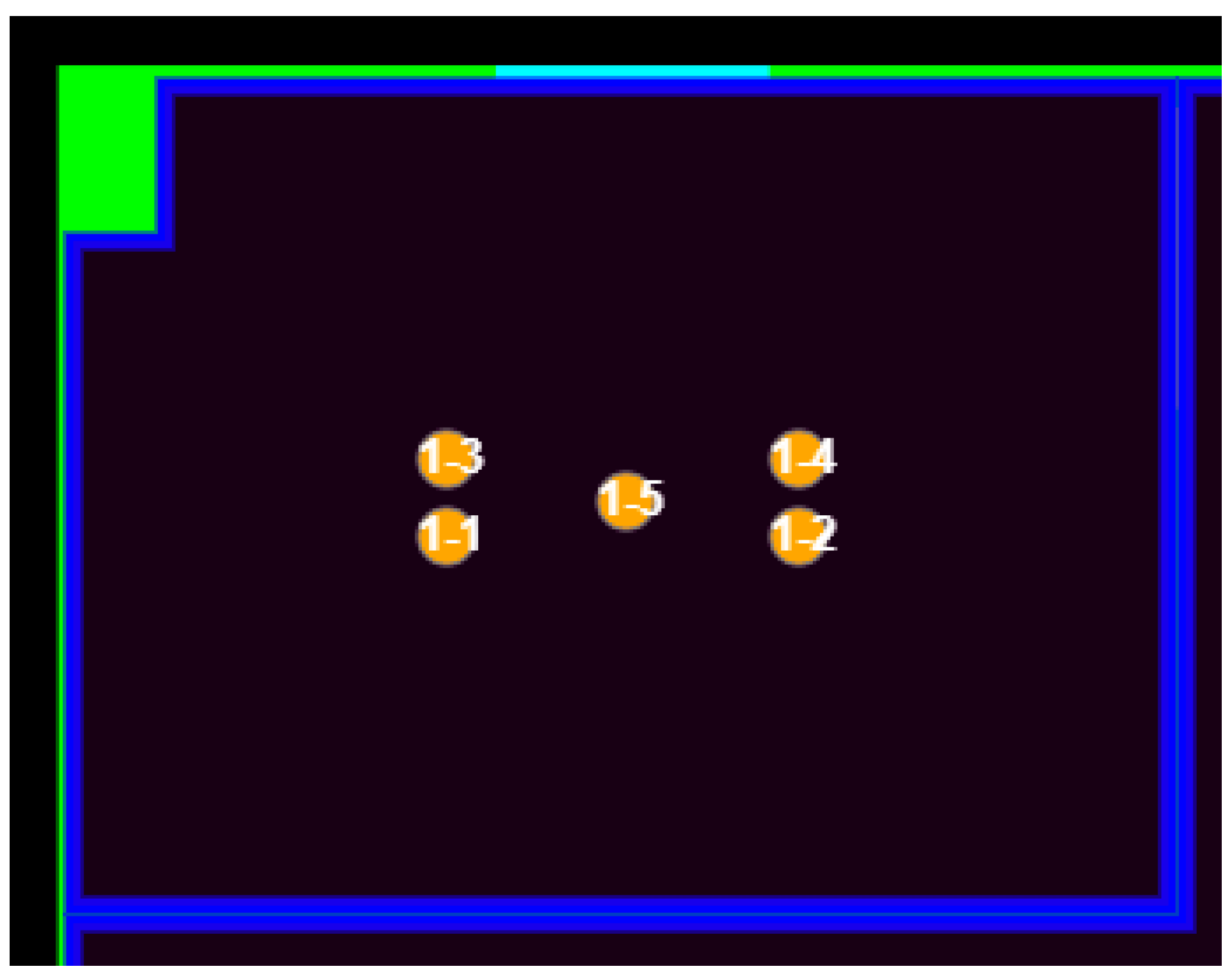
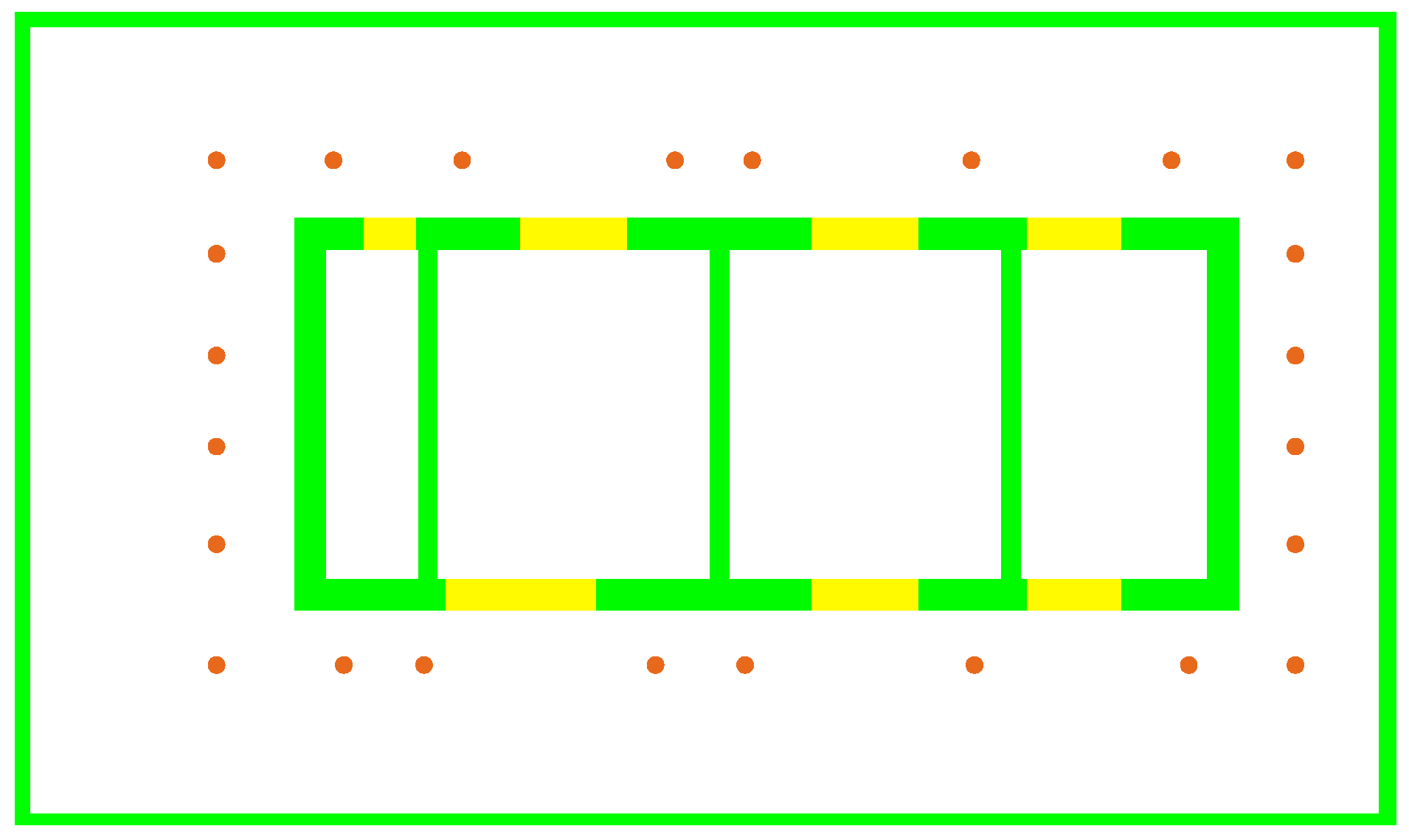
Automated measurement task planning: the robot can autonomously plan measurement tasks for site, including determining the measurement path, identifying measurement points and the corresponding parameters to be measured along the path.
(3)
Non-contact acquisition of highly accurate measurement data: the robot should have the capability to obtain highly accurate measurement data using non-contact measurement methods.

3. Methodology

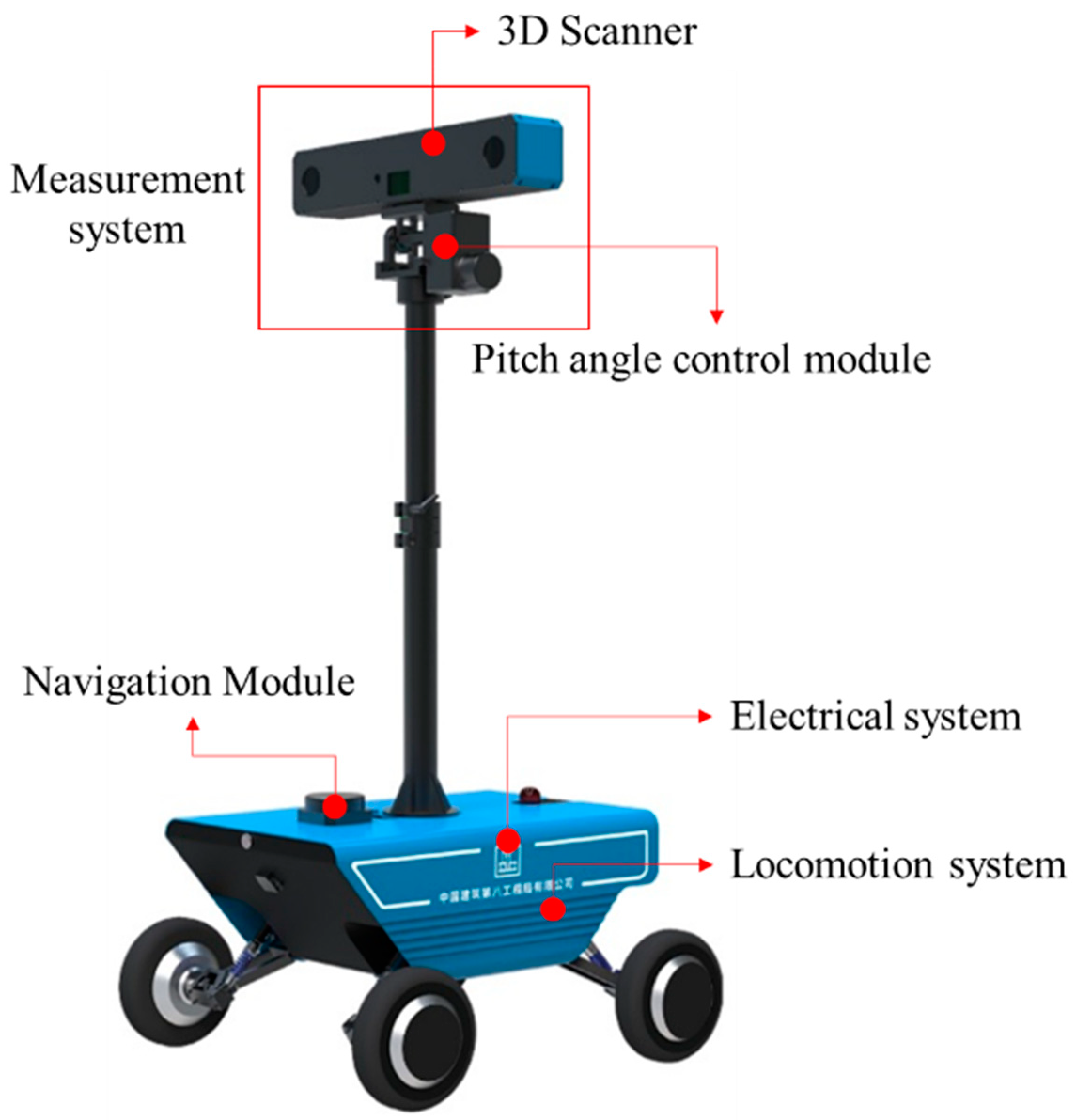
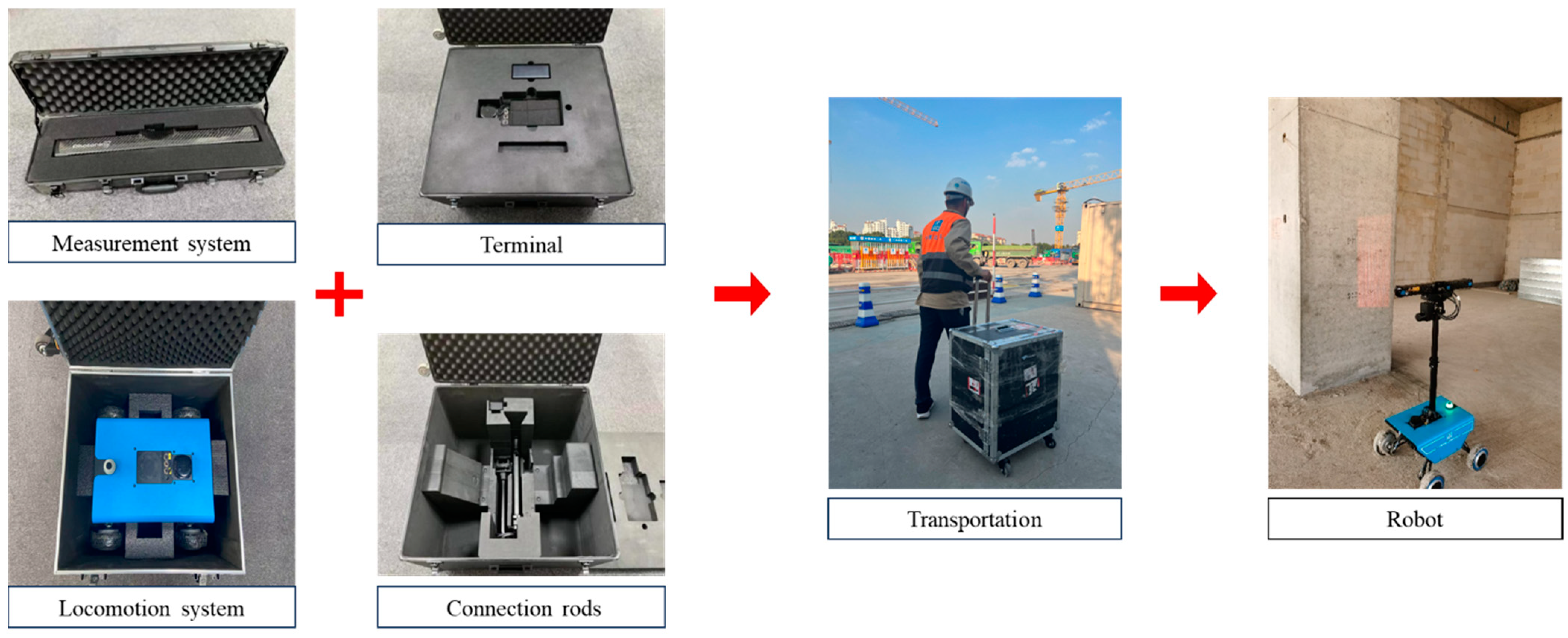
3.1. Design and Configuration of Hardware Systems

3.1.1. Overall Mechanical Design

Figure 1 presents the designed mechanisms for measuring robot. The robot’s mechanisms primarily comprised the locomotion system, electrical system, 3D Scanner, pitch angle control module, and navigation system. The total hardware cost is approximately US $30,000, representing a reduction of approximately 30% compared to commercial 3D laser scanners (for example, the Trimble X7 Scanner 3D Scanning System is priced at around $45,000).
The locomotion system facilitates the robot’s autonomous movement within the construction site, while the electrical system provides the necessary power for the robot to complete its measurement tasks. The 3D scanner is a critical component that captures point cloud data from the measured elements, providing essential data for measurement algorithms. It is connected to the pitch angle control module, which allows for adjustments of the scanner’s angle, thereby enhancing the range of measurements. The 3D Scanner and pitch angle control module constitute the measurement system of the robot. Additionally, the navigation system facilitates unmanned movement. Detailed designs of each component will be presented in the following sections.

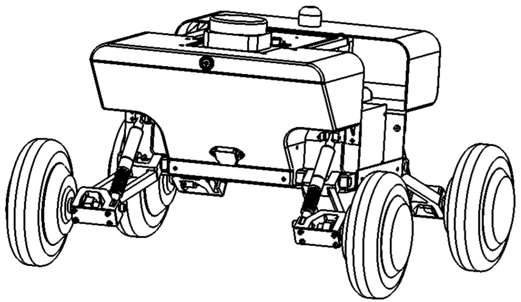
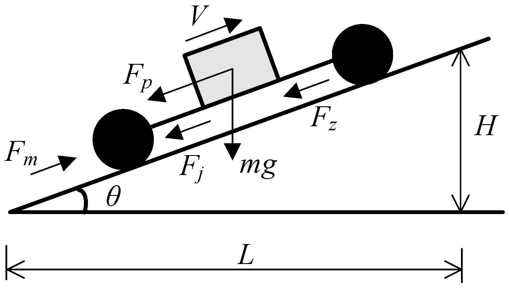
3.1.2. Locomotion System

As depicted in Figure 2, the locomotion system employs a four-wheel differential drive mechanism for precise control, enabling agile movement, excellent obstacle-climbing ability, and adaptability to complex environments. Each of the four wheels can be individually controlled in terms of speed.
Considering the construction project sites and the storage requirements for the robot, the wheelbase width was set at 484 mm, with an axle distance of 430 mm, and the lowest point of the chassis was positioned 135 mm above the ground, which has been shown in Figure 3 and Figure 4. Additionally, each wheel was fitted with independent suspension to reduce equipment vibrations, as illustrated in Figure 5.
The locomotion system guarantees outstanding mobility and obstacle-crossing capability, achieving a maximum speed of up to 5 m/s. It can overcome ground obstacles with a height of up to 5 cm or a width of up to 3 cm. Videos demonstrating the robot navigating obstacles are available in Supplementery Files S1 and S2.

3.1.3. Electrical System

The electrical system primarily includes the drive motor, batteries, and their associated circuits.
To ensure the robot’s capability to navigate slopes in the field, a force analysis was conducted to determine the appropriate drive motor model, as shown in Figure 6. Based on the calculations, the maximum power required for the robot to ascend a 15-degree slope while traveling at 0.3 m/s is 32.3 W.
Based on these calculations, four 200 W drive motors have been selected for the robot. This motor configuration not only satisfies the current power requirements but also provides sufficient power for potential future upgrades.
Furthermore, a 24 V 17.5 Ah capacity battery is incorporated, and a Battery Management System (BMS) has been devised. The BMS discharge protection mechanism encompasses safeguards against short circuits, overloads, and over-temperature issues. It offers current and voltage relay protection in response to abrupt increases in current and sudden drops in voltage.

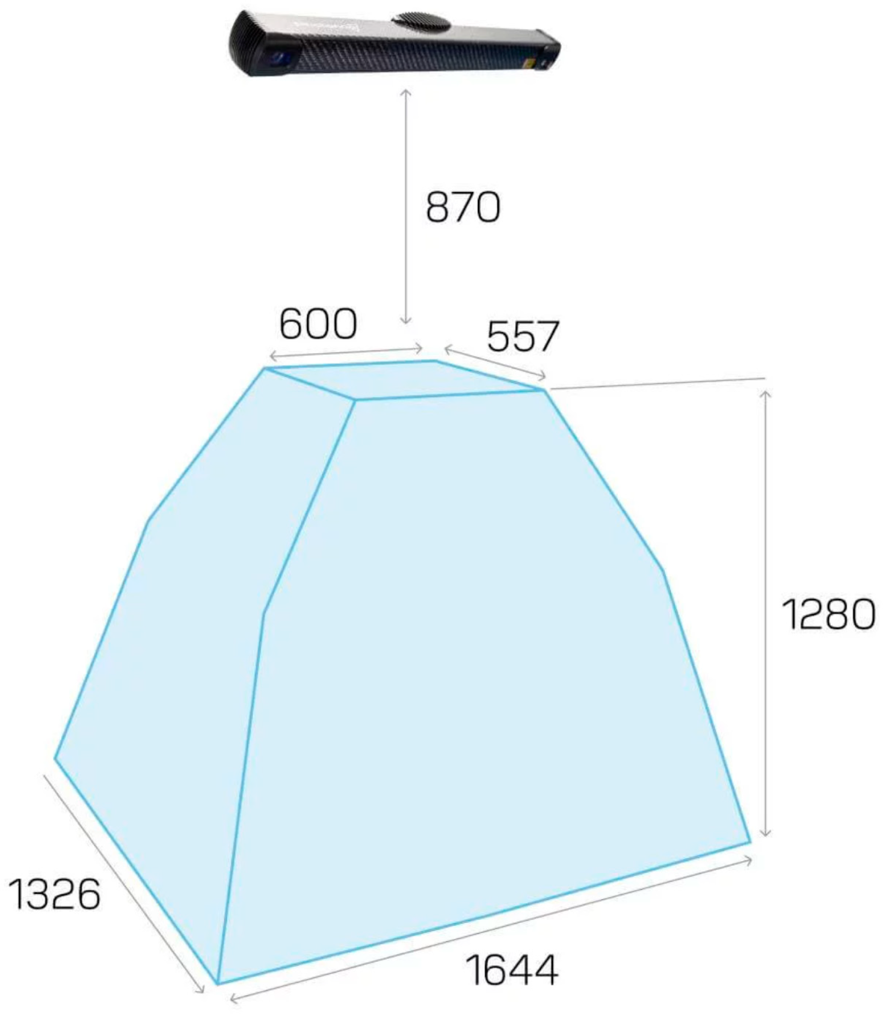
3.1.4. Measurement System

The 3D Scanner and pitch angle control constitute the measurement system of the robot. The 3D Scanner used is the PhoXi 3D Scanner L produced by Photoneo (Figure 7). This scanner is designed specifically for capturing detailed and precise measurements of stationary scenes. Its structured light projection method delivers accurate point cloud data, facilitating rapid localization of any specified component. The scanner’s durability ensures high-quality scans, making it well-suited for the complex challenges encountered in building projects. The parameters of PhoXi 3D Scanner L have been listed in Table 1.
Considering the extensive wall areas involved in on-site civil engineering measurements, a pitch angle control module was employed to extend the measurement range. This module allows the 3D Scanner to achieve various scanning angles, ensuring comprehensive coverage of the measurement object. The pitch control unit features a high-precision tilt sensor that provides real-time horizontal and tilt angles of the 3D scanner, facilitating accurate processing of measurement items based on point cloud data. The attached video in Supplementery File S3 demonstrates the robot adjusting the scanning angles to cover a broader range of measurement areas.

3.1.5. Navigation System

To attain autonomous navigation and positioning for the robot, the navigation system integrates LiDAR, an odometer, and a control center. The LiDAR utilized in the robot (RPLIDAR S2) employs the Time of Flight (TOF), offering a ranging radius of up to 30 m. It is positioned in the middle of the locomotion system, providing a 180° field of vision in front of the robot. This setup ensures comprehensive environmental scanning, enabling autonomous navigation and automatic obstacle avoidance, as demonstrated in Supplementery File S4.
The robot transmits odometer data at a frequency of 20 Hz, which encompasses its position and orientation. These data are sent to control the locomotion system through serial or network ports. In collaboration with autonomously developed navigation and positioning algorithms, precise information regarding the robot’s position can be obtained. Subsequently, the control module generates speed and angular velocity data by integrating its position with the planned measurement task, facilitating more precise navigation to the designated measurement location.

3.2. Development of Key Algorithms

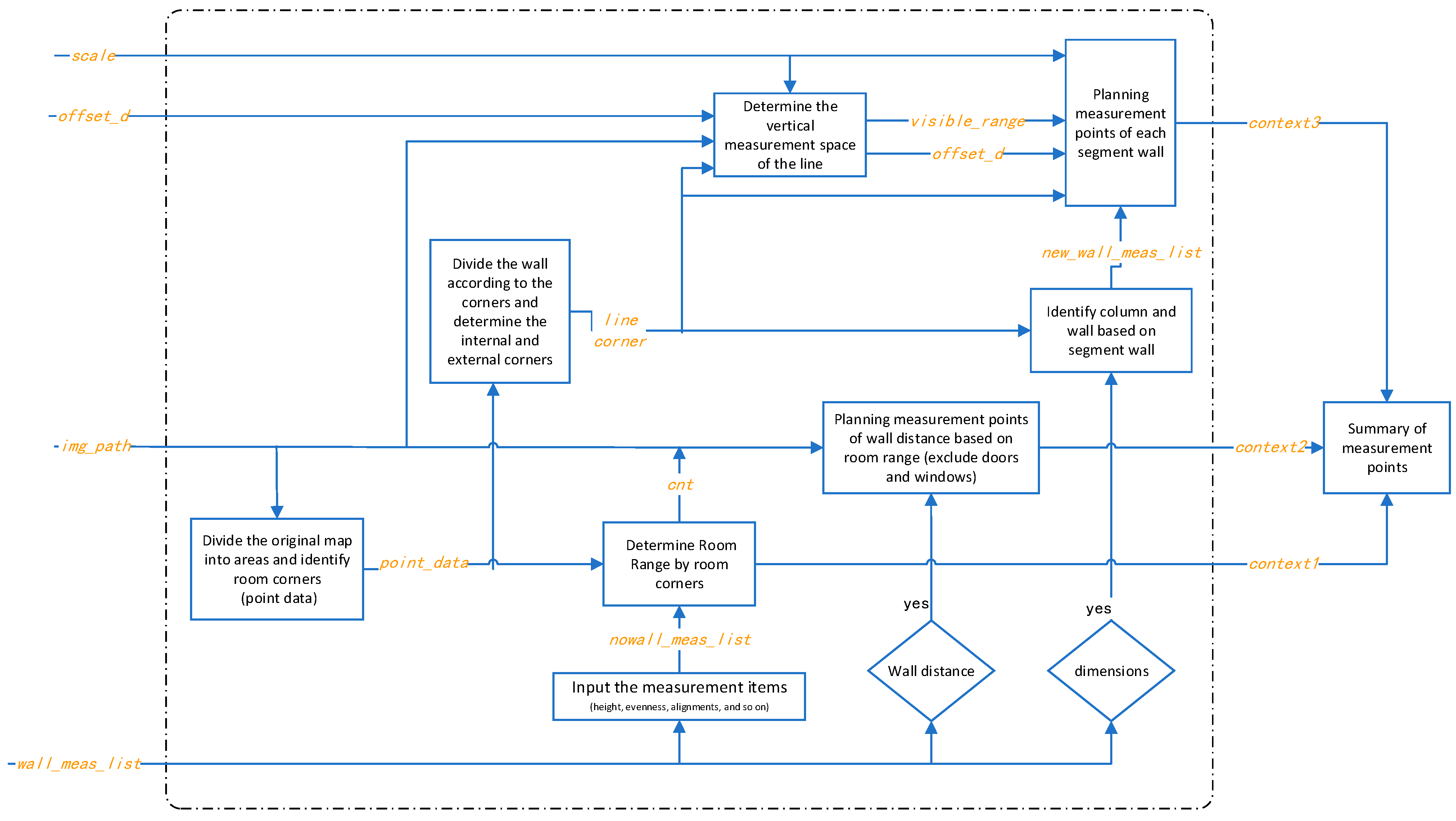
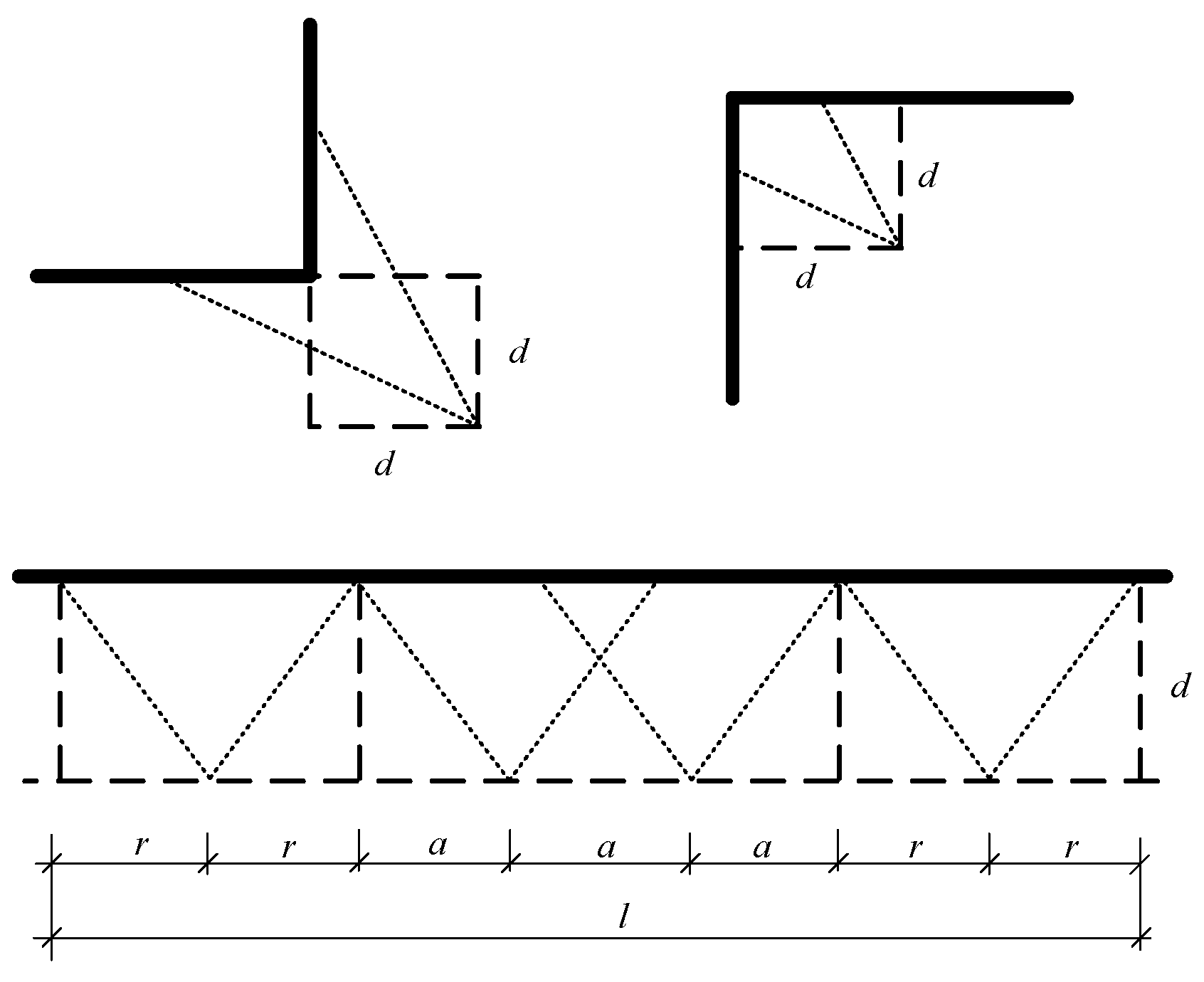
3.2.1. Method for Automated Measurement Task Planning

Given the robot’s primary application in construction engineering, typical scenarios involve residential and office buildings characterized by standard structural and component design. In this context, an automated method for planning measurement tasks has been introduced by utilizing technology for converting and recognizing architectural drawing data.
A measurement points planning method (depicted in Figure 8) has been proposed to facilitate the automated planning of measurement tasks. Specifically, the method starts by identifying components such as doors, windows, and walls in the input drawings. Using a region segmentation algorithm, the processed map is divided into rooms. Following this, the five-point method (Figure 9) is employed to strategically plan measurement points for various parameters, including floor height, roof levelness, and ground flatness within the standard scene (positioning five points in an arrangement that includes up, down, left, right, and center within a room). If the initial five points fail to cover the entire measurement space, extra measurement points will be added based on the principles specified in Figure 10.
Once the measurement points have been determined, a measurement path optimization algorithm will be implemented to create an optimal measurement task that includes all points and parameters. Subsequently, the measurement task is devised, encompassing measurement points, measurement path, and measurement items.
The aforementioned method automatically generates measurement points and provides plans for measurement paths and content based on user-input drawing information, thereby significantly reducing the manual workload associated with planning measurement tasks.

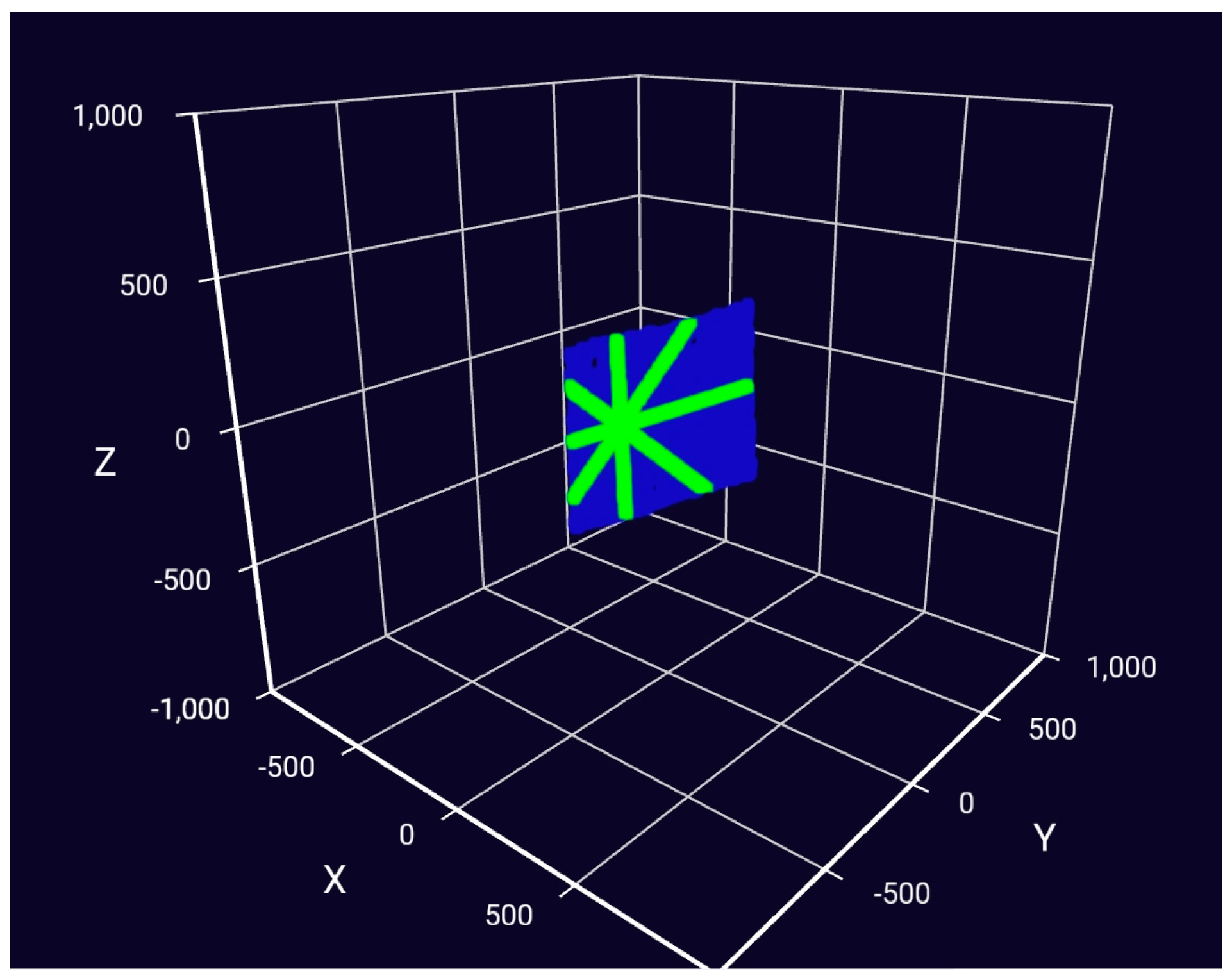
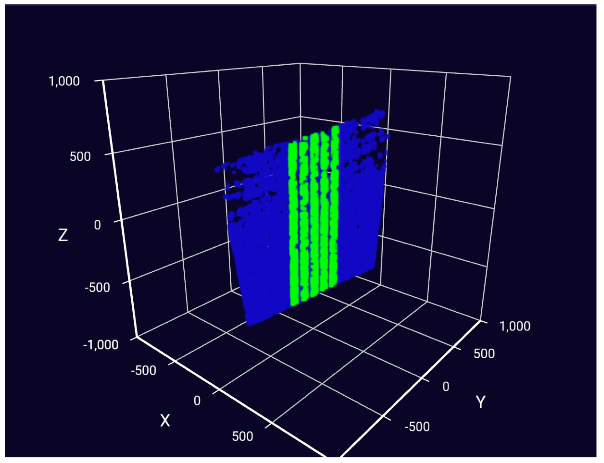
3.2.2. Algorithms for Processing Measurement Data

The Point Cloud Library (PCL) was employed, and specific algorithms were developed for various measurement items based on data acquired from the PhoXi 3D Scanner L. These items include dimensions (such as column dimensions, window, and door sizes), wall evenness, alignments, floor height, and internal and external corner angles.
Moreover, the algorithm incorporates calibration and 3D data processing modules. For calibration, OpenCV is utilized to obtain high-precision spatial pose transformation parameters, enhancing the accuracy of the measurement function. The 3D data processing module utilizes various data processing methods, including 3D data downsampling, filtering, segmentation, principal component analysis, etc. The fundamental principles of these diverse algorithms are summarized in Table 2. Schematic diagrams processing evenness, alignments, and internal and external corner angles were primarily generated using the least squares method for plane fitting, as shown in Figure 11.
In contrast to using all point cloud data, the proposed measurement algorithm utilizes key point cloud data for processing, as presented in Figure 12 and Figure 13. Specifically, the blue points represent the obtained point cloud data, while the green points indicate the selected data, which accounts for about 10% of the total point cloud data. It significantly reduces storage costs while achieving the desired measurement functions. Taking the measurement of evenness as an example, the time from initiating the PhoXi 3D Scanner L to obtaining the measurement value is about 5 s.

3.3. Measuring Accuracy Evaluation

To evaluate the measurement accuracy of the developed robot, experiments were conducted to assess the alignment of a plumb glass plate (with a default alignment of 0 mm), the evenness of a tile floor (with default evenness set at 0 mm), and the external corner angle of a glass plate with a right angle. The measured results are listed in Table 3.
The results indicate that the measurement accuracy of the developed robot is commendable. The average measurement accuracy for alignments, evenness, and external corner angle is within 1 mm.
Simultaneously, a further comparison was conducted between the robot and manual measurement methods. It involved using the developed robotic measurement system and conventional measuring tools, including straight edge rule, inside and outside right-angle measuring ruler, measuring tape, and total station. Varied construction quality control parameters for different measurement objects were acquired and presented in Table 4.
The data presented in the table indicate that the measured data obtained by the robot exhibit relatively minor discrepancies compared to manual measurement results for various items. Therefore, it can be concluded that the on-site measuring robot developed is well-suited for post-construction quality assessment of building projects.

4. Measuring Process

The hardware systems of the robots can be assembled and interconnected, enhancing the portability and transportability of the robot. This robot system includes a measurement system (PhoXi 3D Scanner L), a control terminal (for monitoring the robot’s status, downloading measurement tasks, and receiving/uploading measurement data), the locomotion system, and connecting rods. As illustrated in Figure 14, each component can be packed into a portable box for easy transportation and later assembled to establish a functioning robot system.
After completing the assembly of the robot, the measurement process follows the process outlined in Figure 15. The primary steps are as follows:
(1)
Upload the architectural drawings to the web platform.
(2)
Generate the measurement points on the web platform based on the architectural drawings.
(3)
Create a measurement task that includes all planned measurement points.
(4)
Upload the measurement task to the server.
(5)
Download the measurement task onto the control terminal and send it to the robot.
(6)
Specify the starting point of the robot’s measurement task through the control terminal and issue the “Start Measurement Task” command.
(7)
Robot executes the measurement task automatically.
(8)
The control terminal receives the measurement data and uploads the data to the server once connected to the network.
(9)
The web platform receives the data and automatically generates a measurement report with data evaluation.
(10)
Print the report to complete the measurement process.
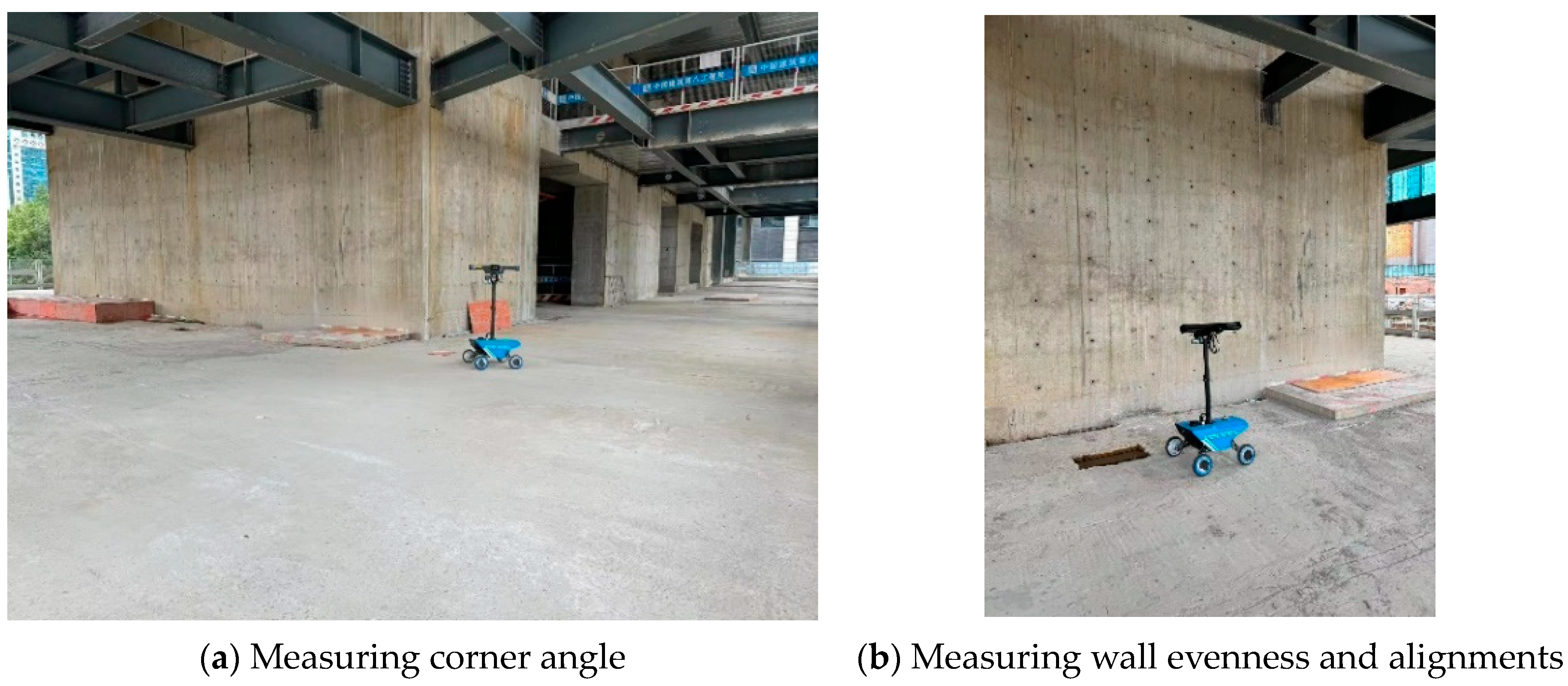
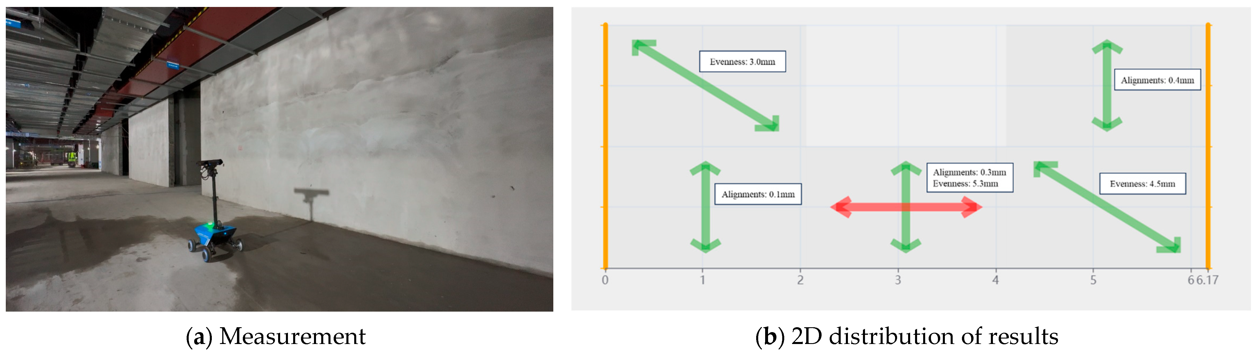
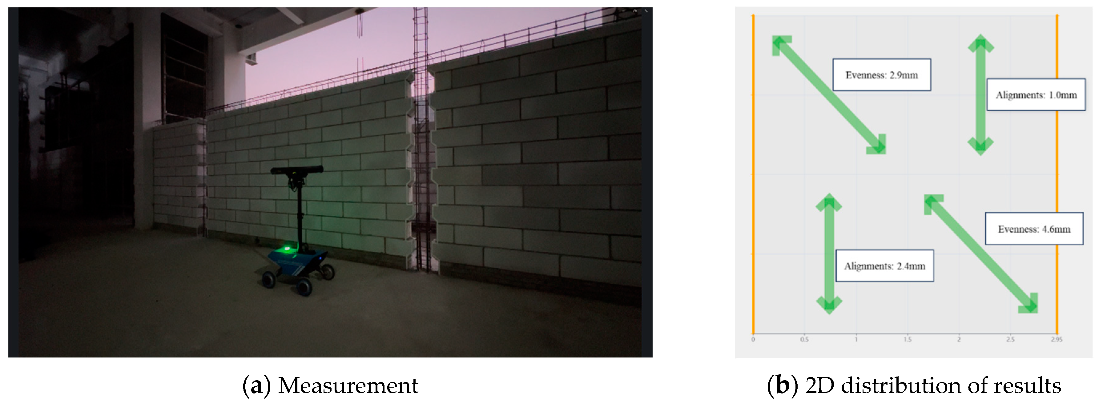
5. Application

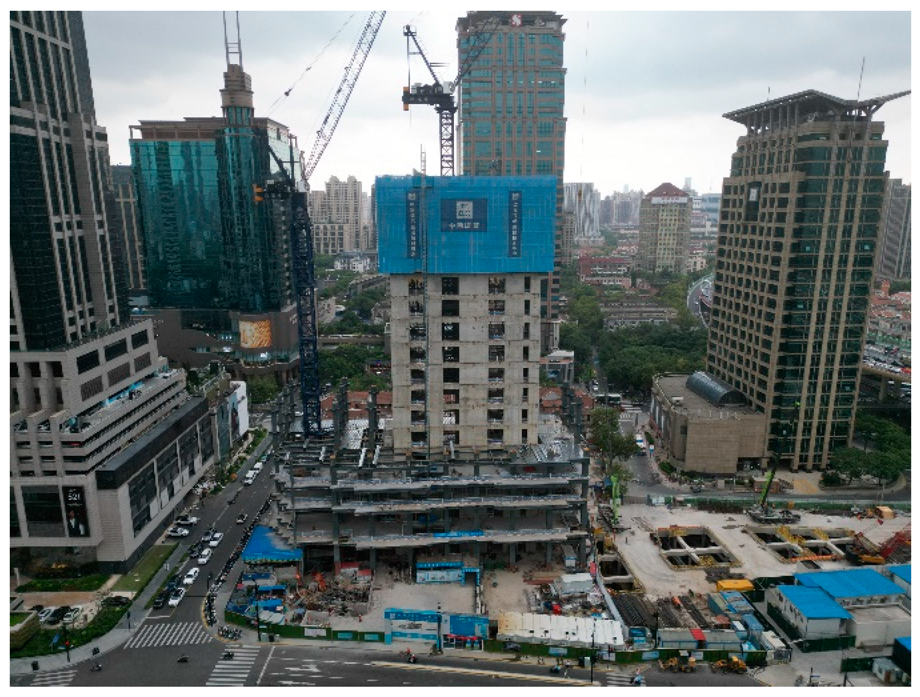
5.1. Shangxianfang Protective Renovation Project

The robot was applied in a building project in Shanghai, China, named Shangxianfang Protective Renovation Project (Figure 16). It is a structure comprising a steel pipe concrete frame and a concrete core tube. In this application, the developed robot was used to measure wall evenness, alignments, floor height, and the internal and external corner angles of the concrete core tube.
According to the measuring process presented in Section 4, the architectural drawings were first simplified to retain only the information about walls and openings (with walls represented by green lines and openings by yellow lines). The simplified drawing was then uploaded to the web platform to plan the measurement points and tasks. The original and processed drawings with designated measurement points have been presented in Figure 17 and Figure 18. Subsequently, the measurement task was transmitted and assigned to the robot through the control terminal. The robot performing the measurement is illustrated in Figure 19.
This measurement session involved a total of 24 measurement points, resulting in 131 measurement items. The data were automatically transmitted via the network, and a comprehensive measurement report was generated, as provided in Supplementery File S5.
The entire measurement process took approximately 30 min, with a rate of about 0.14 m2/s. For comparison, manual measurement of a typical residence with a size of 85–125 m2, including the same measurement items, would take at least 20 min (excluding data transcription) by skilled personnel, with a measurement speed of about 0.1 m2/s.
Additionally, the manual measurement process typically requires collaboration between two or more inspectors, while the robot reduces the workforce to just one operator. Therefore, compared to manual measurement, the on-site measuring robot increases efficiency by approximately 40% and reduces labor costs by at least 50%.

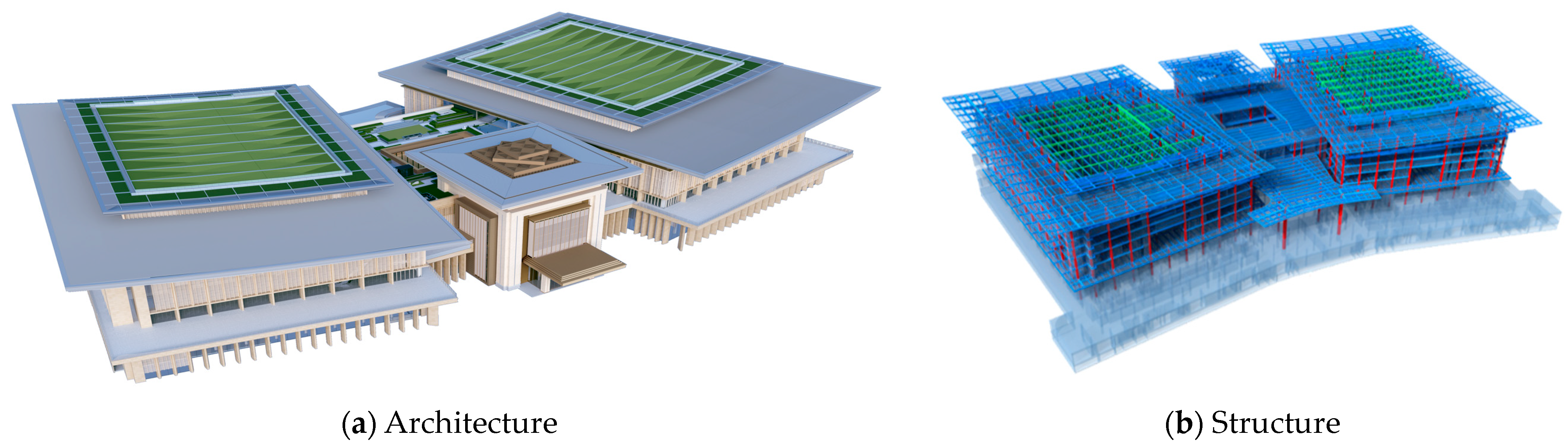
5.2. Shenzhen International Convention Center

The robot was also applied in another building project in Shenzhen, China, named the Shenzhen international convention center. As shown in Figure 20, the building consists of steel–concrete columns, steel beam frames, and reinforced concrete shear walls.
The robot was employed to assess the evenness and alignment of shear walls in the basement and brick walls in the above-ground structure. The measuring process follows the same steps as shown in Figure 15, with further details provided in Supplementery File S6. It can be seen that the robot autonomously navigated the site until it reached each designated measurement point, after which the task was executed, and the data were transmitted back to the terminal.
The measurement results are illustrated in Figure 21 and Figure 22, with red arrows indicating areas that fail to meet construction quality standards. As presented, the 2D distribution of the wall measurement results, generated via the web interface, clearly illustrates the quality distribution of the walls, which allows on-site managers to easily identify areas with poor construction quality and take appropriate corrective actions.

6. Limitations

Despite the significance of this investigation, there were still some limitations. For instance, the weight of the robot (33.2 kg) poses challenges in situations such as stair navigation or elevator use, where manual lifting is required. Reducing the robot’s weight by using lightweight materials or optimizing its configuration will be necessary in the future. Additionally, the preprocessing of architectural drawings for task planning is time-consuming, and efforts will focus on refining and enhancing drawing recognition algorithms to streamline this process. Moreover, the robot cannot provide real-time output of measurement data during operation, as data are only uploaded upon task completion. This creates a risk of data loss from unexpected issues like power failures or obstacles. Developing more robust data-saving mechanisms and backup solutions would help ensure reliable and continuous performance.

7. Conclusions

Post-construction on-site quality measurement, traditionally performed manually, is essential for ensuring the quality of building projects. Recent developments in measurement robots, particularly those incorporating robot dogs and 3D laser scanners, have aimed to improve efficiency. However, these systems often face challenges, including substantial storage requirements for point cloud data, reliance on specialized post-processing software, and high costs. Although some cost-effective robots with multiple sensors have emerged, they still encounter limitations in handling diverse measurement tasks and often require specific environmental conditions. Therefore, this article addresses these challenges by developing an automated on-site measuring robot designed specifically for post-construction quality assessment and applied it in two building projects. The conclusions have been drawn as follows:
(1)
The robot is equipped with a comprehensive hardware setup, including a locomotion system, electrical system, 3D scanner, pitch angle control module, and navigation system. This configuration enables unmanned, mobile, and continuous measurement operations. It also developed an automated method for planning measurement tasks and processing data using algorithms based on the Point Cloud Library (PCL). It is estimated that that the system provides approximately a 30% reduction in total investment compared to commercial 3D laser scanners.
(2)
The robot can measure various parameters, including dimensions (e.g., column sizes and window and door dimensions), wall evenness, alignments, floor height, and internal and external corner angles. The proposed measurement algorithms focus on retaining only effective point cloud data, leading to a reduction of about 90% in data storage requirements. The accuracy and reliability of these measurements have been validated through experiments.
(3)
In practical applications, the robot demonstrated a 40% improvement in efficiency over manual measurements for similar tasks and achieved a minimum of 50% reduction in labor costs, highlighting the robot’s effectiveness in enhancing measurement productivity and reducing operational costs. It also shows that the developed on-site measuring robot offers a practical and automated solution for post-construction quality assessment in building projects.
Overall, this investigation demonstrates the potential of the developed robot to offer significant improvements in both efficiency and cost-effectiveness, advancing the field of post-construction quality measurement.

Supplementary Materials

The following supporting information can be downloaded at: https://www.mdpi.com/article/10.3390/buildings14103085/s1.

Author Contributions

Conceptualization, Y.Y.; software, S.W.; validation, H.W. and S.W.; investigation, H.W. and L.H.; resources, M.M. and Y.Y.; data curation, L.H.; writing—original draft preparation, H.W.; writing—review and editing, H.W.; project administration, M.M.; funding acquisition, Y.Y. All authors have read and agreed to the published version of the manuscript.

Funding

This research was funded by Shanghai Sailing Program (No. 23YF1452200), CCEED Technology R&D Program (CCEED-2022-3-14, CCEED-2022-2-30), National Key R&D Program of China (Grant No. 2022YFC3802203).

Data Availability Statement

The raw data supporting the conclusions of this article will be made available by the authors on request.

Conflicts of Interest

All authors are employed by China Construction Eighth Engineering Division Co., Ltd.

References

  1. Liu, L.; Chen, I.M.; Kayacan, E.; Tiong, L.K.; Maruvanchery, V. Automated construction quality assessment: A review. In Proceedings of the 2015 10th International Symposium on Mechatronics and its Applications (ISMA), Sharjah, United Arab Emirates, 8–10 December 2015; IEEE: Piscataway, NJ, USA, 2015; pp. 1–6. [Google Scholar]
  2. Lee, A.Y.; Seo, H.C.; Park, E.S. Development of a Manually Operated Mobile Robot That Prints Construction Site Layouts. Machines 2022, 10, 1192. [Google Scholar] [CrossRef]
  3. Desa, U.N. World population prospects 2019: Highlights. N. Y. (US) United Nations Dep. Econ. Soc. Aff. 2019, 11, 125. [Google Scholar]
  4. Bock, T. The future of construction automation: Technological disruption and the upcoming ubiquity of robotics. Autom. Constr. 2015, 59, 113–121. [Google Scholar] [CrossRef]
  5. Gharbia, M.; Chang-Richards, A.; Lu, Y.; Zhong, R.Y.; Li, H. Robotic technologies for on-site building construction: A systematic review. J. Build. Eng. 2020, 32, 101584. [Google Scholar] [CrossRef]
  6. You, S.; Kim, J.H.; Lee, S.H.; Kamat, V.; Robert, L.P., Jr. Enhancing perceived safety in human–robot collaborative construction using immersive virtual environments. Autom. Constr. 2018, 96, 161–170. [Google Scholar] [CrossRef]
  7. Chang, S.; Siu, M.F.F.; Li, H.; Luo, X. Evolution pathways of robotic technologies and applications in construction. Adv. Eng. Inform. 2022, 51, 101529. [Google Scholar] [CrossRef]
  8. De Santos, P.G.; Estremera, J.; Garcia, E.; Armada, M. A service robot for construction industry. In Proceedings of the Proceedings World Automation Congress, Seville, Spain, 28 June–1 July 2004; IEEE: Piscataway, NJ, USA, 2004; Volume 15, pp. 441–446. [Google Scholar]
  9. King, N.; Bechthold, M.; Kane, A.; Michalatos, P. Robotic tile placement: Tools, techniques and feasibility. Autom. Constr. 2014, 39, 161–166. [Google Scholar] [CrossRef]
  10. Nematollahi, B.; Xia, M.; Sanjayan, J. Current progress of 3D concrete printing technologies. In Proceedings of the ISARC, International Symposium on Automation and Robotics in Construction, Lille, France, 3–7 June 2024; IAARC Publications: Lyon, France, 2017; p. 34. [Google Scholar]
  11. Koch, C.; Paal, S.G.; Rashidi, A.; Zhu, Z.; König, M.; Brilakis, I. Achievements and challenges in machine vision-based inspection of large concrete structures. Adv. Struct. Eng. 2014, 17, 303–318. [Google Scholar] [CrossRef]
  12. Poorghasem, S.; Bao, Y. Review of robot-based automated measurement of vibration for civil engineering structures. Measurement 2023, 207, 112382. [Google Scholar] [CrossRef]
  13. Construction Index. Fetch, Spot! Robot Dog Gathers Construction Data; Construction Index: March, UK, 22 October 2021; Available online: www.theconstructionindex.co.uk/news/view/fetch-spot-robot-dog-gathers-construction-data (accessed on 20 October 2021).
  14. Frangoul, A. Boston Dynamics’ Four-Legged Robot Has Been Gathering Data at a Major Construction Site in London; CNBC: Fort Lee, NJ, USA, 12 November 2020; Available online: www.cnbc.com/2020/11/12/boston-dynamics-robot-gathering-data-at-construction-site-in-london.html (accessed on 20 October 2021).
  15. Şahan, N.H. Get to Know the Leica BLK2FLY and Leica BLK ARC; Surveying Group: Osborne Park, WA, USA, 4 August 2022; Available online: https://shop.leica-geosystems.com/leica-blk/blk2fly/blog/get-know-leica-blk2fly-and-leica-blk-arc (accessed on 20 March 2022).
  16. Yan, R.J.; Kayacan, E.; Chen, I.M.; Tiong, L.K. A novel building post-construction quality assessment robot: Design and prototyping. In Proceedings of the 2017 IEEE/RSJ International Conference on Intelligent Robots and Systems (IROS), Vancouver, BC, Canada, 24–28 September 2017; IEEE: Piscataway, NJ, USA, 2017; pp. 6020–6023. [Google Scholar]
  17. Yan, R.J.; Kayacan, E.; Chen, I.M.; Tiong, L.K.; Wu, J. QuicaBot: Quality inspection and assessment robot. IEEE Trans. Autom. Sci. Eng. 2018, 16, 506–517. [Google Scholar] [CrossRef]
  18. Authority, E.M. Building and Construction Authority. In Handbook for Solar Photovoltaic (PV) Systems; Building and Construction Authority: Singapore, 2017. [Google Scholar]
  19. Nadeem, Z.; Nadeem, H.; Khan, J.A.; Ullah, A. Wall-Distance Measurement for Indoor Mobile Robots. In Intelligent Sustainable Systems: Selected Papers of WorldS4 2021, Volume 2; Springer Nature: Singapore, 2021; pp. 1–9. [Google Scholar]
  20. Wang, K.; Li, D.; Li, L.; Chi, S. The Research on the Mobile Measuring Robot Technology. J. Phys. Conf. Ser. 2022, 2402, 012037. [Google Scholar] [CrossRef]
  21. Zahari, M.; Mutalib, N.A.; Affendi, N.N.; Hashim, N.; Hadi, D.A.; Johari, S.H.; Ab Wahab, N.; Ahmad, S. Development of mobile robot for measuring distance using optical quadrature encoder. Indones. J. Electr. Eng. Comput. Sci. 2020, 18, 745–749. [Google Scholar] [CrossRef]
  22. Wang, J.; Tao, B.; Gong, Z.; Yu, S.; Yin, Z. A mobile robotic measurement system for large-scale complex components based on optical scanning and visual tracking. Robot. Comput.-Integr. Manuf. 2021, 67, 102010. [Google Scholar] [CrossRef]
Figure 1. Designed mechanisms for measuring robot.
Buildings 14 03085 g001
Figure 2. Locomotion system.
Buildings 14 03085 g002
Figure 3. Vertical view of robot.
Buildings 14 03085 g003
Figure 4. Lateral view of robot.
Buildings 14 03085 g004
Figure 5. Suspension.
Buildings 14 03085 g005
Figure 6. The force conditions of the robot while ascending a slope.
Buildings 14 03085 g006
Figure 7. PhoXi 3D Scanner L.
Buildings 14 03085 g007
Figure 8. Measurement points planning method.
Buildings 14 03085 g008
Figure 9. Five-point method.
Buildings 14 03085 g009
Figure 10. Arrangement of extra measurement points.
Buildings 14 03085 g010
Figure 11. Measurement item acquisition based on least squares fitting plane.
Buildings 14 03085 g011
Figure 12. Key point of evenness.
Buildings 14 03085 g012
Figure 13. Key point of alignment.
Buildings 14 03085 g013
Figure 14. Assembly and transportation of the robot.
Buildings 14 03085 g014
Figure 15. Measurement process.
Buildings 14 03085 g015
Figure 16. Shangxianfang Protective Renovation Project.
Buildings 14 03085 g016
Figure 17. The original floor plan.
Buildings 14 03085 g017
Figure 18. The processed floor plan.
Buildings 14 03085 g018
Figure 19. The robot during the measurement.
Buildings 14 03085 g019
Figure 20. Shenzhen international convention center.
Buildings 14 03085 g020
Figure 21. Measurement of shear walls in the basement.
Buildings 14 03085 g021
Figure 22. Measurement of brick walls in the above-ground structure.
Buildings 14 03085 g022
Table 1. D Scanner L.
No.ParametersValue
1Resolution (3D points)Up to 3.2 M
2Scanning range870~2150 mm
3Optimal scanning distance1239 mm
4Scanning area at sweet spot1080 × 772 mm
5Point to point distance0.524 mm
6Calibration accuracy0.2 mm
8Scanning time250~2750 ms
9Dimensions77 × 68 × 616 mm
10Baseline550 mm
113D points throughput16 million points per second
Table 2. Fundamental principles of different algorithms.
ItemsFundamental Principles of Algorithms
EvennessBased on the point cloud data, a plane is determined using the least squares method. The distances from all points in the calculation area to the plane are examined, and the extreme value is identified as the measurement output.
AlignmentBased on the point cloud data, a plane is fitted using the least squares method, and inclination sensor data is used to adjust the plane to align with the world coordinate system. The measurement output is calculated based on the normal vector of this plane.
Corner anglesBased on the point cloud data, two intersecting planes are determined using the least squares method. Following this, the angle between the normal vectors of these two planes is calculated and returned as the measurement output value.
DimensionsBased on the point cloud data, a plane is determined using the least squares method. Subsequently, the boundary of the plane is traversed, and the dimensions of the boundary are returned as the measurement output value.
HeightCombining the height of the robot (1.2 m) and the point cloud depth.
Table 3. Measured results of standard components (mm).
Items1st Time2nd Time3rd Time4th Time5th TimeAverage
Alignments0.620.480.630.680.370.556
Evenness0.650.870.560.820.770.734
External corner angle0.710.830.790.70.690.744
Table 4. Comparison between the robot and manual measurement methods (mm).
ItemsObjectsConventional Measuring ToolsAverage DeviationMaximum Deviation
EvennessWallStraight edge rule0.441.05
AlignmentsWallStraight edge rule0.991.95
Internal corner angleWallInside and outside right-angle measuring ruler1.0281.48
External corner angleWallInside and outside right-angle measuring ruler1.121.46
DimensionsWindowMeasuring tape1.992.47
Height/Total station3.55
Disclaimer/Publisher’s Note: The statements, opinions and data contained in all publications are solely those of the individual author(s) and contributor(s) and not of MDPI and/or the editor(s). MDPI and/or the editor(s) disclaim responsibility for any injury to people or property resulting from any ideas, methods, instructions or products referred to in the content.

