Design and Analysis of a New Prefabricated Foundation for Onshore Wind Turbines

 ,
, 
Abstract
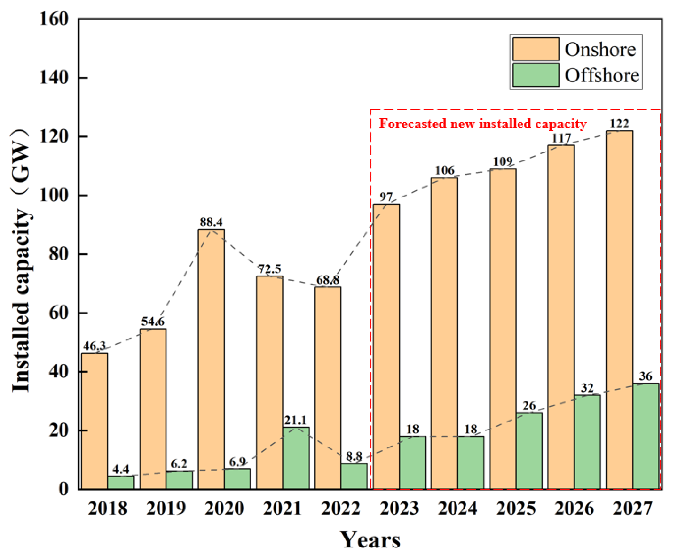
1. Introduction
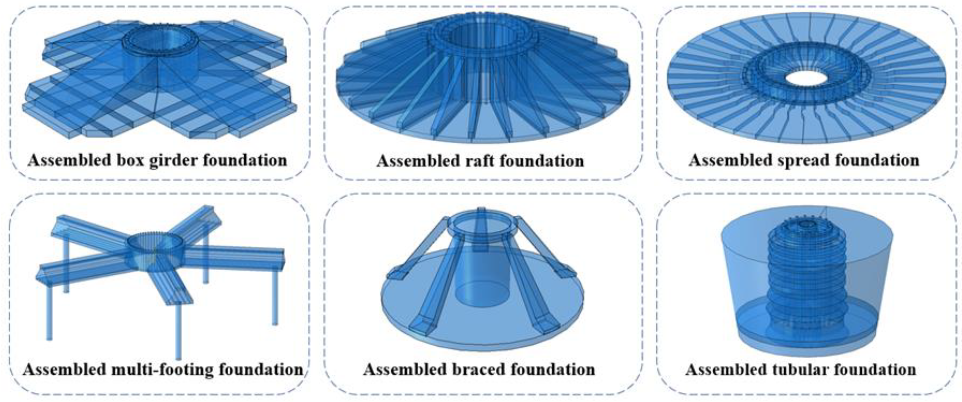
2. New Prefabricated Foundation for Onshore Wind Turbines
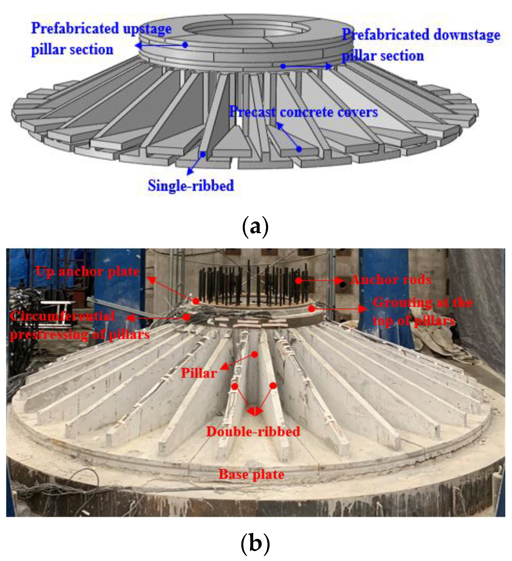
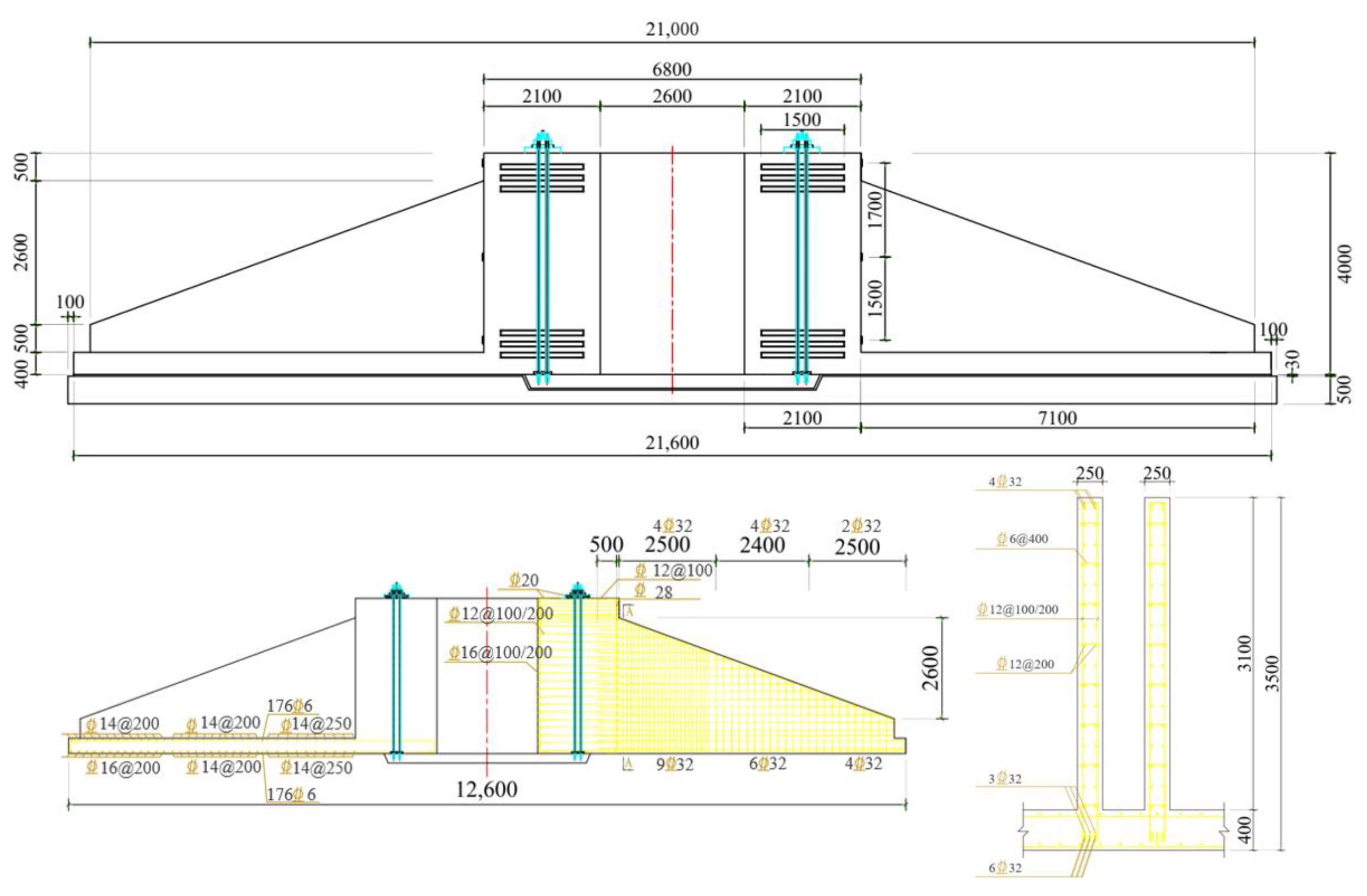
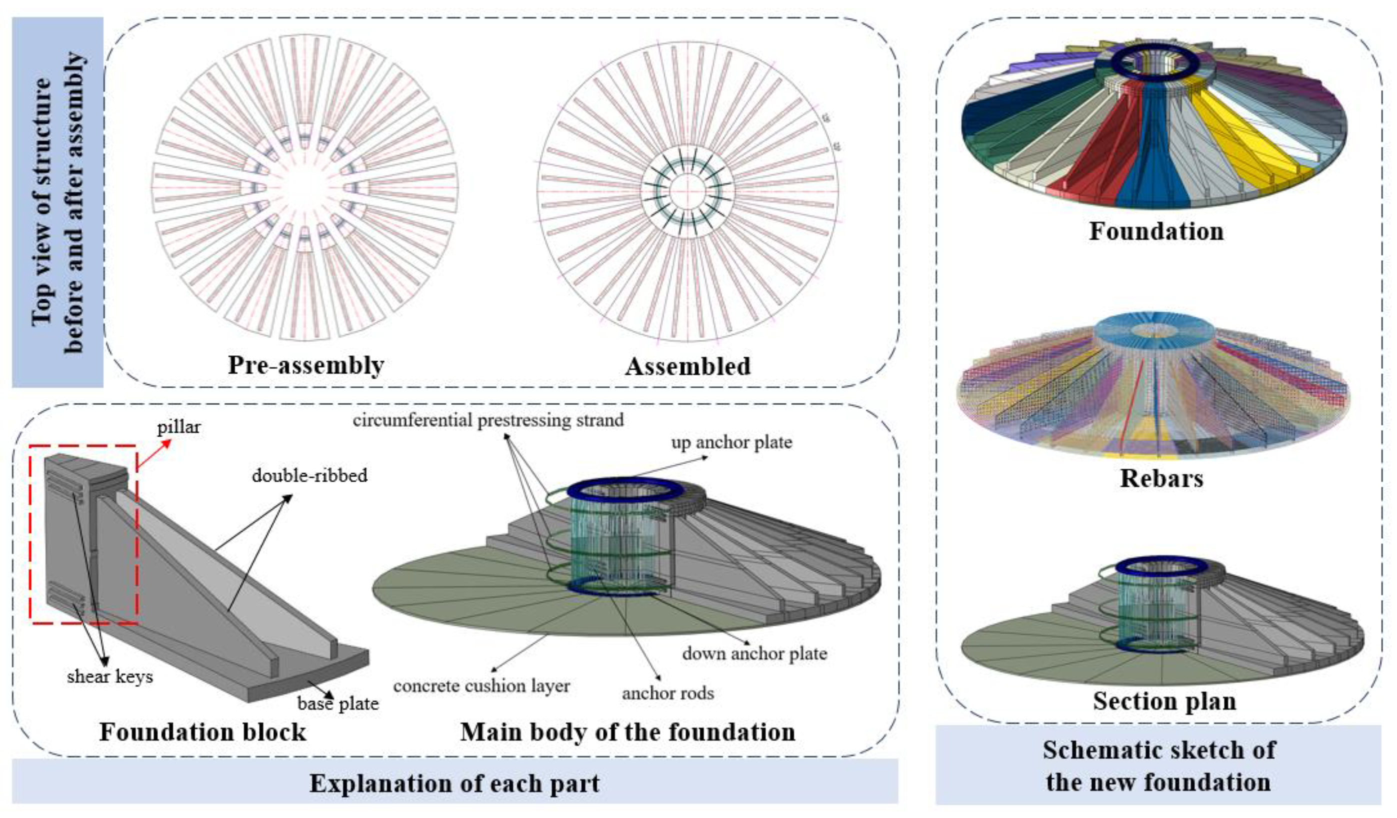
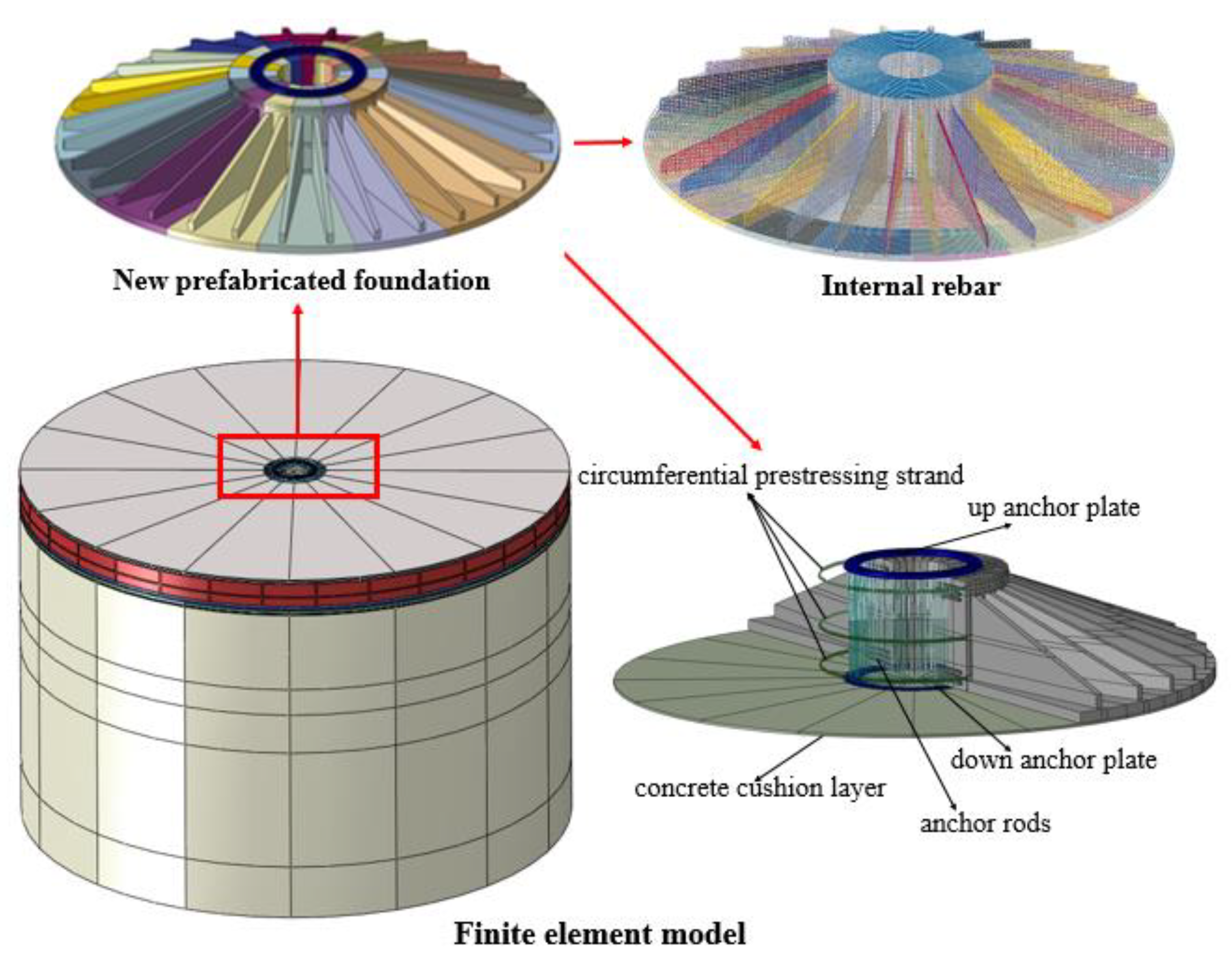
2.1. Foundation Structure
2.2. Construction Process of the New Prefabricated Foundation
3. Theoretical Calculations
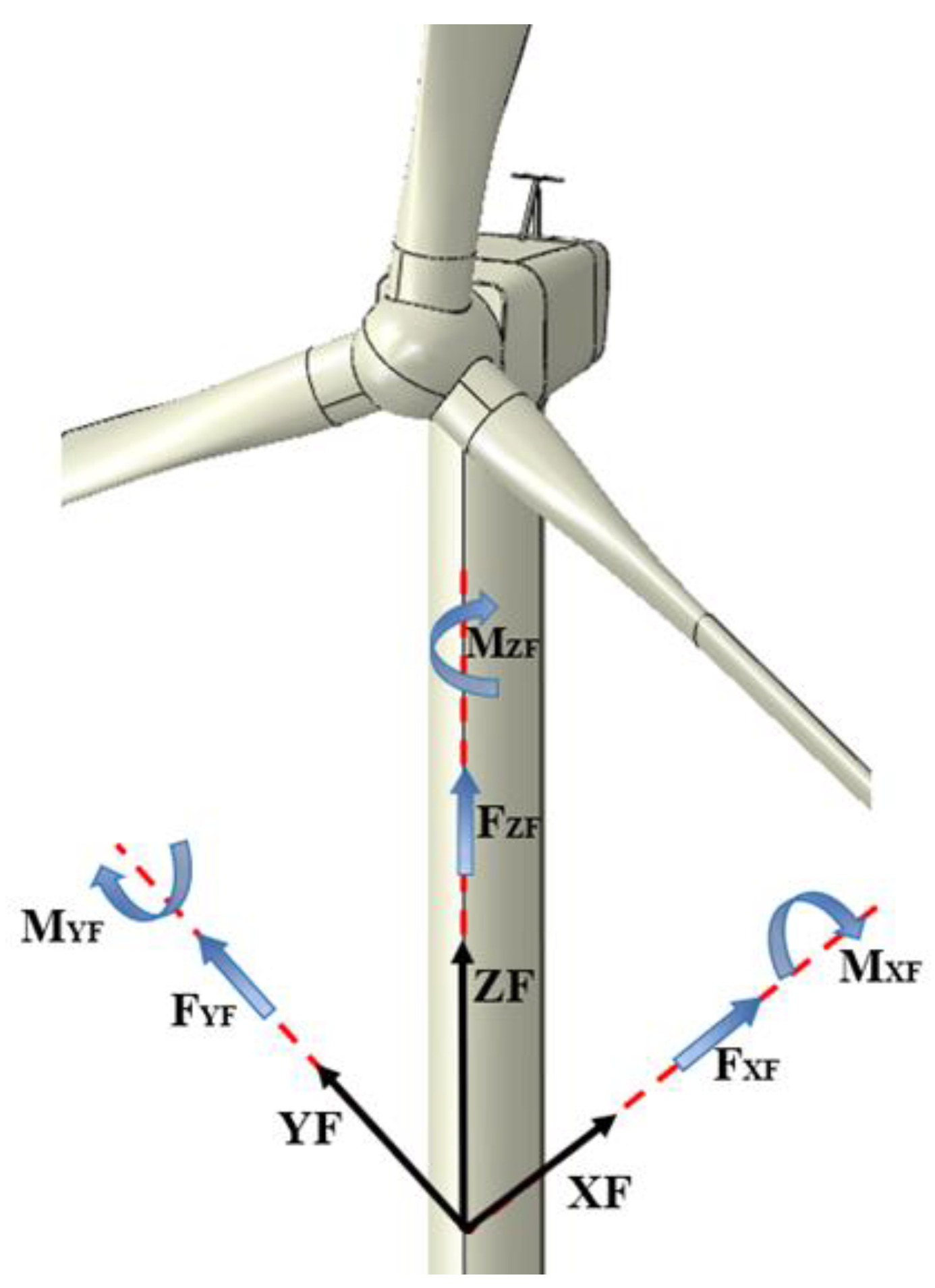
3.1. Wind Turbine Loads
3.2. Theoretical Calculations
3.2.1. Calculation of Structural Stability
3.2.2. Calculation of Rebars
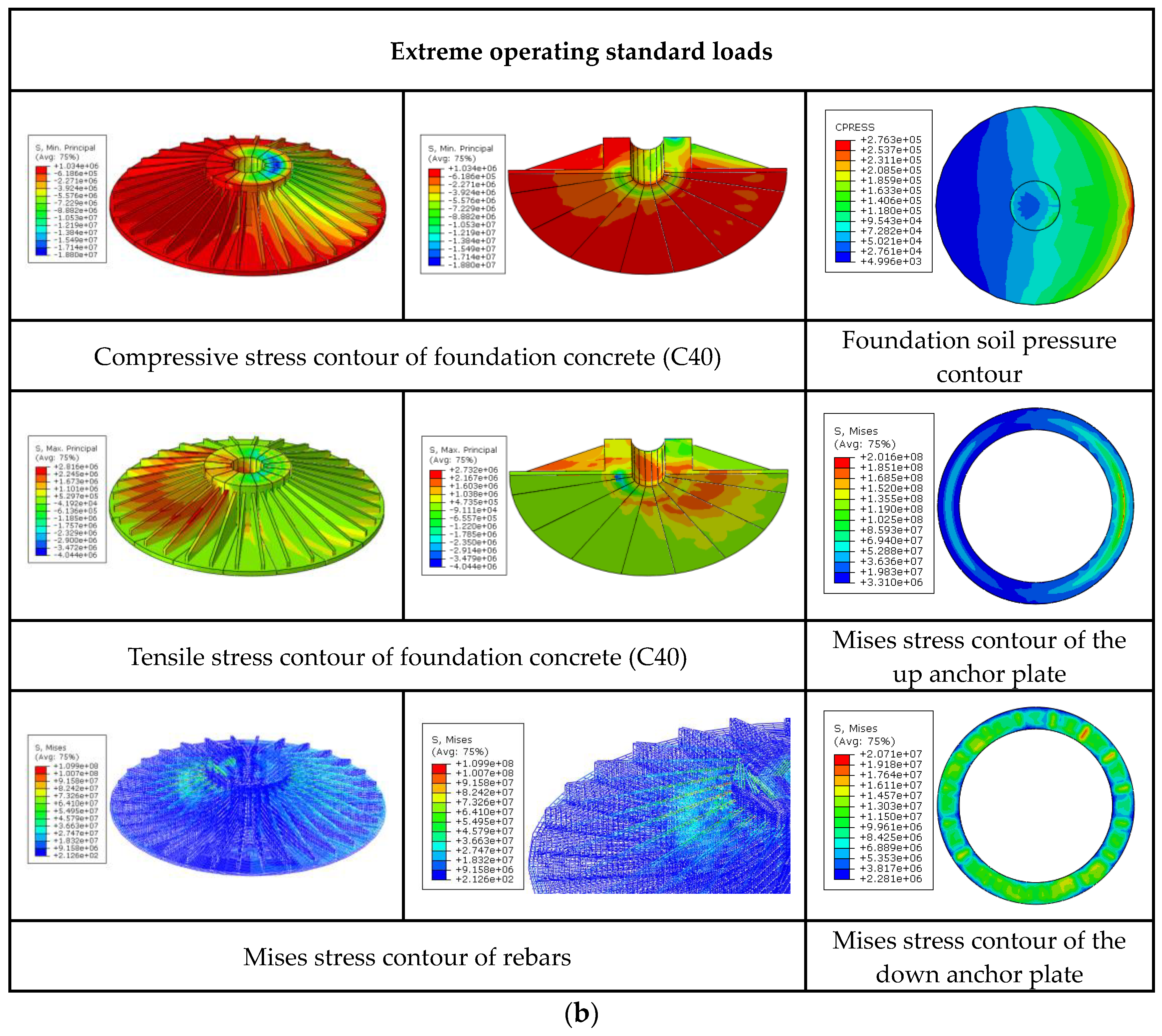
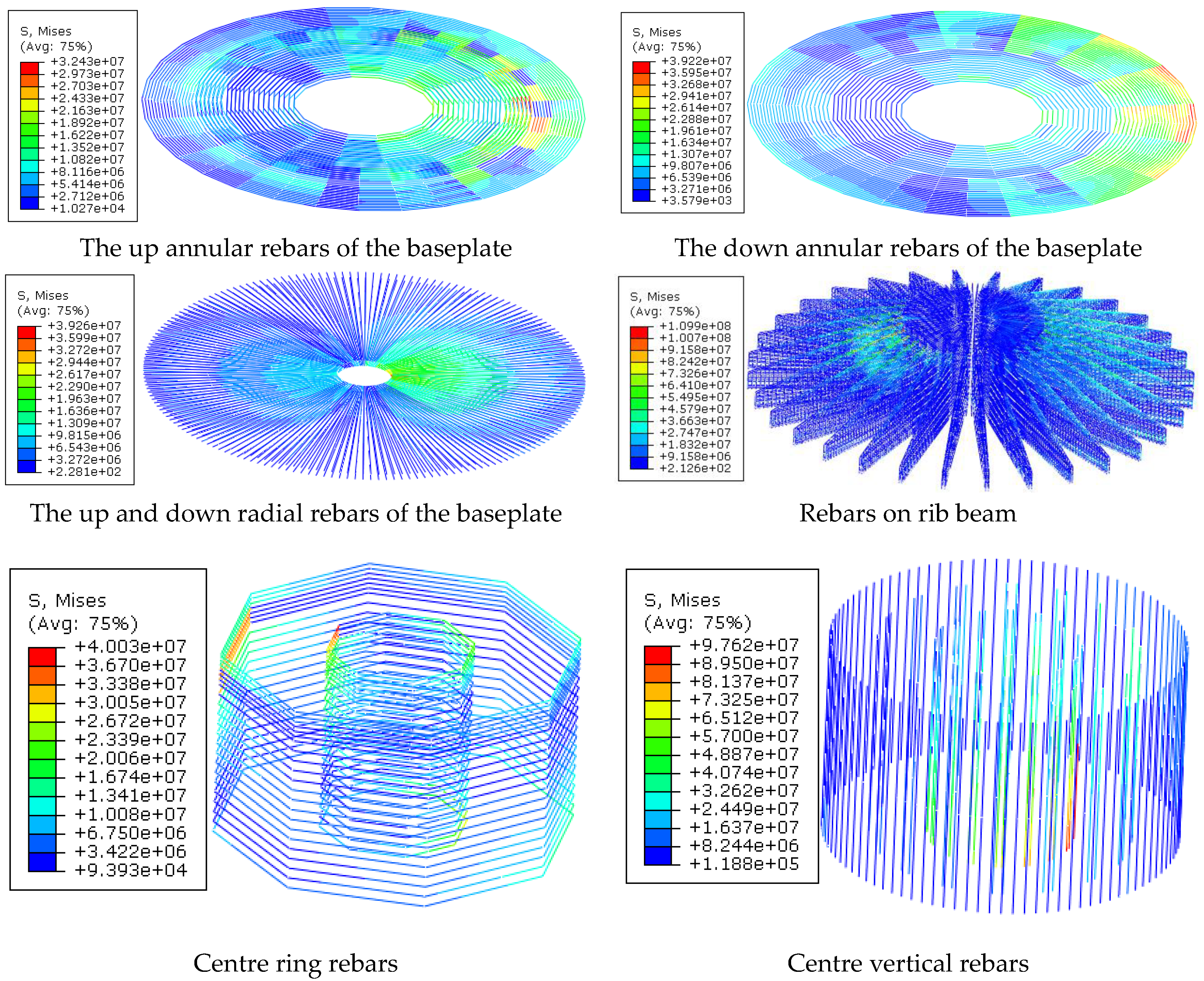
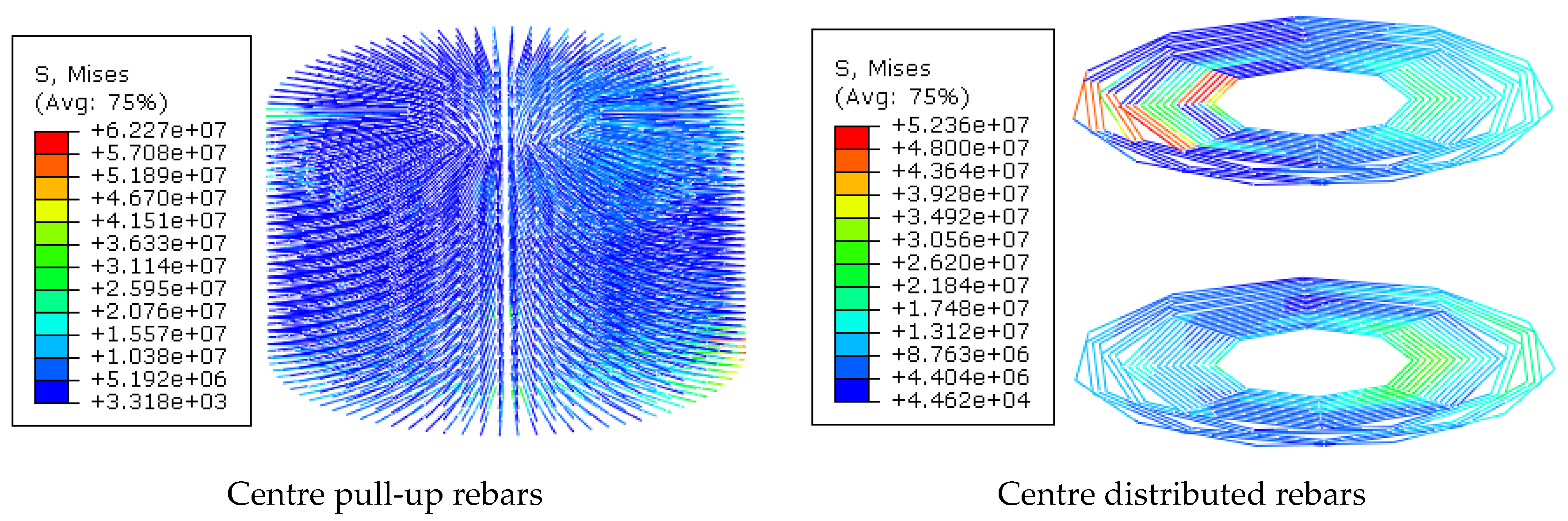
4. Structural FEM Analysis
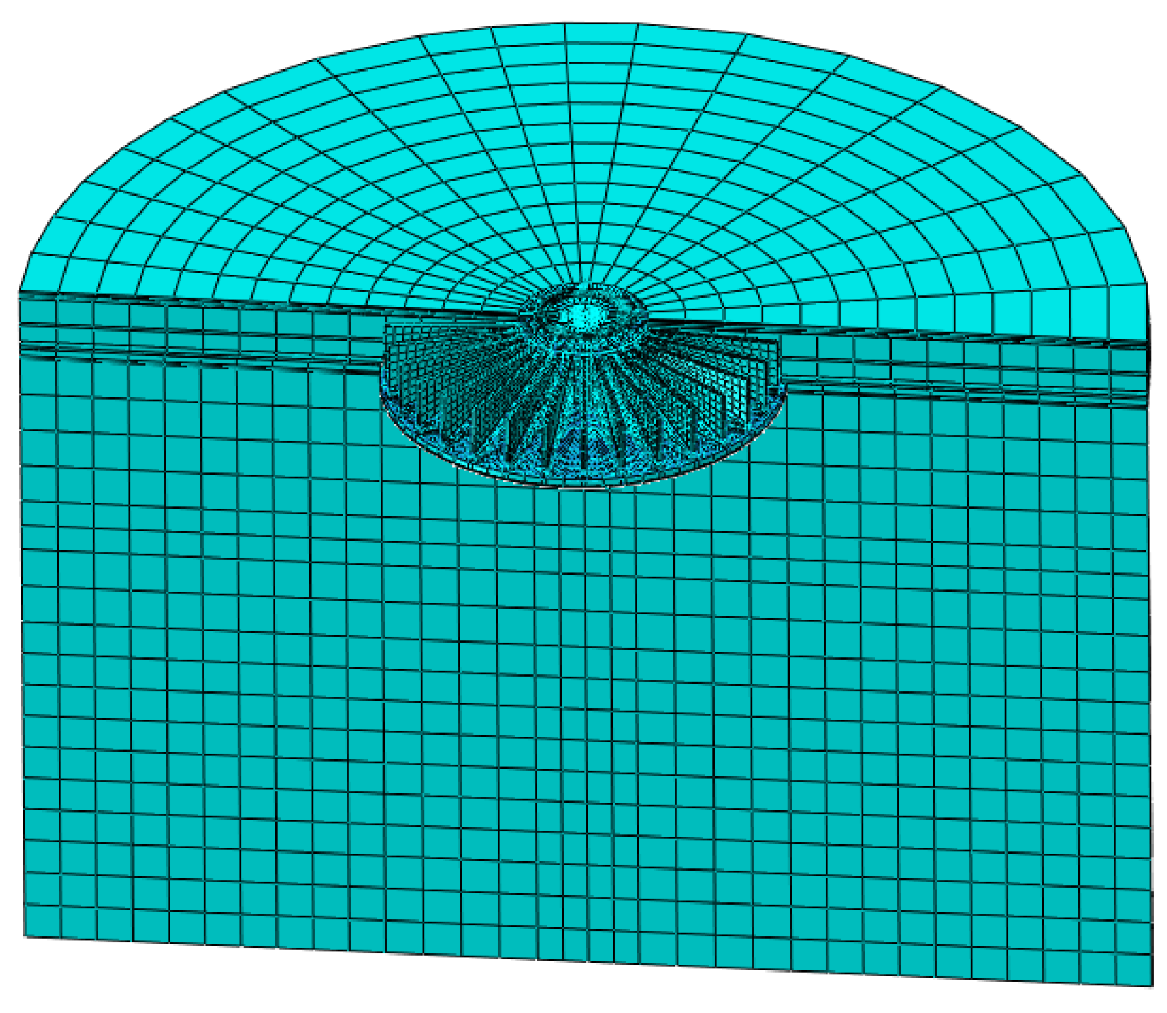
4.1. Finite Element Model
4.2. Structural Finite Element Analysis
5. Conclusions
- (1)
- A new type of prefabricated foundation for onshore wind turbines is proposed. The new prefabricated foundation consists of 16 prefabricated blocks. Compared with the extended foundation at the same position, the concrete amount is reduced by 30.00%, and the rebars amount is reduced by 34.69%, significantly reducing the amount of reinforcing steel and concrete. At the same time, the new prefabricated foundation blocks can be precast in bulk indoors by means of a precast concrete plant, which can significantly reduce costs and ensure quality. The new prefabricated foundation combines the prefabricated girder slab foundation and the table pillar section as a whole, reducing the number and type of prefabricated components while improving construction efficiency.
- (2)
- Based on the specification, the new prefabricated foundation was inspected and calculated. The calculation results indicate that the foundation’s stress and reinforcement meet the specification requirements. Additionally, structural calculations based on several specifications show that the new prefabricated foundation meets the design requirements of the specifications in terms of bearing capacity, stability against overturning, stability against sliding, settlement, and other factors. The new prefabricated foundation is stable and safe enough.
- (3)
- Based on the finite element analysis software ABAQUS, the rebars stress, concrete stress, and foundation inclination rate of the new prefabricated foundation were analyzed. Through the analysis of the stress distribution of foundation concrete and rebars, it can be found that the stress distribution is reasonable and uniform, and the load transfer is fine. The maximum stress of the rebars and concrete does not exceed the specification limit, and the concrete does not crack.
- (4)
- The tilt rates of the bottom flange of the foundation and the bottom flange of the fan are 0.49‰ and 0.89‰, respectively, which do not exceed the normative permissible value of 3‰, and the tilt rate of the foundation meets the specification requirements. The design of the new prefabricated foundation is reasonable. It meets the specification requirements and the actual bearing demand, and it has great mechanical properties and stability. It provides theoretical support for subsequent measurement of indoor experiments and field construction.
Author Contributions
Funding
Data Availability Statement
Acknowledgments
Conflicts of Interest
Abbreviations
| Pkmax | is the maximum pressure value at the bottom edge of the foundation under the standard combination of load effect. |
| Pkmin | is the minimum pressure value at the bottom edge of the foundation under the standard combination of load effect. |
| Nk | is the vertical load transmitted from the superstructure to the top surface of the foundation. |
| Mk | is the resultant moment value of the superstructure to the top surface of the foundation. |
| Gk | is the weight of foundation and overlying soil. |
| W | is the resistance moment of the base surface. |
| A | is the base area. |
| is the maximum pressure coefficient of the foundation’s bottom surface. | |
| R | is the radius of the foundation’s bottom surface. |
| FR | is the anti-sliding force under the basic combination of load effect. |
| is the friction coefficient between the foundation bottom and foundation. | |
| Fs | is the design value of sliding force under the basic combination of load effect. |
| is the structural importance coefficient, and the structural safety level is 1.1 for the first level and 1.0 for the second level. | |
| is the structural coefficient, and 1.3 is taken in the calculation of anti-sliding stability and 1.6 is taken in the calculation of anti-overturning stability. | |
| MR | is the anti-overturning moment under the basic combination of load effect. |
| MS | is the design value of overturning moment under the basic combination of load effect. |
| d | is the diameter of the new prefabricated foundation. |
| s | is the final settlement value of the foundation. |
| is the foundation settlement value calculated using the layered sum method. | |
| ψs | is an empirical coefficient for settlement calculations. |
| n | is the number of soil layers divided within the depth of the foundation settlement calculation. |
| Esi | is the compression modulus of the soil in layer i below the base of the extended foundation. |
| P0k | is the additional stress at the base of the extended foundation for the standard combination of load effects. |
| zi, zi−1 | are the distances from the base of the extended foundation to the base of the i, i−1 layer of soil. |
| are the average additional stress coefficients in the range from the calculation point at the base of the extended foundation to the base of the i and i−1 layer of soil. | |
| fspk | is the eigenvalue of foundation bearing capacity. |
| Pjmax | is the maximum net reaction force at the base edge. |
| P1′ | is the net reaction force at the bottom of the foundation to calculate the strip. |
| ac′ | is the width of the net reaction force on the foundation bottom surface. |
| is the maximum crack width of the foundation slab | |
| is the member force characteristic factor | |
| is the coefficient of strain inhomogeneity of the longitudinal tensile reinforcement between cracks | |
| is the stress in the longitudinal tensile plain reinforcement of reinforced concrete members calculated on the basis of quasi-permanent combinations of loads/equivalent stress in the longitudinal tensile reinforcement of prestressed concrete members calculated on the basis of standard combinations. | |
| is the modulus of elasticity of the reinforcement | |
| is the distance from the outer edge of the outermost longitudinal tension reinforcement to the base plate of the tension zone | |
| is the equivalent diameter of the longitudinal reinforcement in the tension zone | |
| is the reinforcement ratio of longitudinal tensile reinforcement based on the effective tensile concrete section area. |
References
- Li, C.; Mogollón, J.M.; Tukker, A.; Steubing, B. Environmental Impacts of Global Offshore Wind Energy Development until 2040. Environ. Sci. Technol. 2022, 56, 11567–11577. [Google Scholar] [CrossRef] [PubMed]
- Guo, Y.; Wang, H.; Lian, J. Review of Integrated Installation Technologies for Offshore Wind Turbines: Current Progress and Future Development Trends. Energy Convers. Manag. 2022, 255, 115319. [Google Scholar] [CrossRef]
- Gielen, D.; Gorini, R.; Wagner, N.; Leme, R.; Gutierrez, L.; Prakash, G.; Asmelash, E.; Janeiro, L.; Gallina, G.; Vale, G.; et al. Global Energy Transformation: A Roadmap to 2050. 2019. Available online: https://www.h2knowledgecentre.com/content/researchpaper1605 (accessed on 15 October 2023).
- Yang, T.; Pan, Y.; Yang, Y.; Lin, M.; Qin, B.; Xu, P.; Huang, Z. CO2 Emissions in China’s Building Sector through 2050: A Scenario Analysis Based on a Bottom-up Model. Energy 2017, 128, 208–223. [Google Scholar] [CrossRef]
- Borthwick, A.G.L. Marine Renewable Energy Seascape. Engineering 2016, 2, 69–78. [Google Scholar] [CrossRef]
- Global Wind Energy Council. GWEC Global Wind Report 2023; Global Wind Energy Council: Sao Paulo, Brazil, 2023. [Google Scholar]
- Duffy, A.; Hand, M.; Wiser, R.; Lantz, E.; Dalla Riva, A.; Berkhout, V.; Stenkvist, M.; Weir, D.; Lacal-Arántegui, R. Land-Based Wind Energy Cost Trends in Germany, Denmark, Ireland, Norway, Sweden and the United States. Appl. Energy 2020, 277, 114777. [Google Scholar] [CrossRef]
- Faber, T. Tower and Foundation. In Wind Power Technology: An Introduction; Springer International Publishing: Cham, Switzerland, 2023; pp. 291–318. [Google Scholar]
- Al-Shetwi, A.Q. Sustainable Development of Renewable Energy Integrated Power Sector: Trends, Environmental Impacts, and Recent Challenges. Sci. Total Environ. 2022, 822, 153645. [Google Scholar] [CrossRef] [PubMed]
- Bradford, T. Solar Revolution: The Economic Transformation of the Global Energy Industry; MIT Press: Cambridge, MA, USA, 2008. [Google Scholar]
- Zohuri, B. Navigating the Global Energy Landscape Balancing Growth, Demand, and Sustainability. J. Mat. Sci. Apl. Eng. 2023, 2, 7. [Google Scholar]
- Bai, J.; Wang, R.; Wang, Y.; Yang, Q. A review of onshore wind turbine prefabricated foundation structures. J. Civ. Environ. Eng. 2023, 1–15. [Google Scholar]
- Shang, Z.; Wang, F.; Yang, X. The Efficiency of the Chinese Prefabricated Building Industry and Its Influencing Factors: An Empirical Study. Sustainability 2022, 14, 10695. [Google Scholar] [CrossRef]
- Song, H.; Cong, O.; Hao, H.; Xu, Y. Research on mechanical properties of prefabricated foundation of wind turbine generators. Bulid. Struct. 2018, 48, 96–100. [Google Scholar] [CrossRef]
- Diógenes, J.R.F.; Claro, J.; Rodrigues, J.C.; Loureiro, M.V. Barriers to Onshore Wind Energy Implementation: A Systematic Review. Energy Res. Soc. Sci. 2020, 60, 101337. [Google Scholar] [CrossRef]
- El-Abidi, K.M.A.; Ghazali, F.E.M. Motivations and Limitations of Prefabricated Building: An Overview. Appl. Mech. Mater. 2015, 802, 668–675. [Google Scholar] [CrossRef]
- Wang, W.; Gao, Y.; Wang, Z.; Zhang, L.; An, Z.; Shao, S. An Experimental Study on Plate Splicing of Prefabricated Plate Foundation. Buildings 2023, 13, 2114. [Google Scholar] [CrossRef]
- De Lana, J.A.; Magalhães, P.A.A., Jr.; Magalhães, C.A.; Magalhães, A.L.M.A.; De Andrade Junior, A.C.; De Barros Ribeiro, M.S. Behavior Study of Prestressed Concrete Wind-Turbine Tower in Circular Cross-Section. Eng. Struct. 2021, 227, 111403. [Google Scholar] [CrossRef]
- Zhang, Y. Study on Application of Prefabricated Steel Foundation in Wind Power Tower. Master’s Thesis, Tongji University, Shanghai, China, 2018. [Google Scholar]
- Chen, Z.; Li, H.; Chen, A.; Yu, Y.; Wang, H. Research on Pretensioned Modular Frame Test and Simulations. Eng. Struct. 2017, 151, 774–787. [Google Scholar] [CrossRef]
- Adrian, C.; Doug, K. Tower Foundation with Concrete Box Girder Beams. U.S. Patent 10982406, 20 April 2021. [Google Scholar]
- Marta, C.D.; Rüdiger, M.; Ali Mohammadi, M. Mold Part Set for Wind Turbine Ground Foundation and Wind Turbine Ground Foundation. WO2022174912A1, 25 August 2022. [Google Scholar]
- Anker Foundations. “Wind Turbine Foundations” [EB/OL]. Available online: https://www.anker-foundations.com/en/wind-turbine-foundation/ (accessed on 1 October 2023).
- Wu, X.; Li, W.; Liu, W. Bearing Platform Unit and Modular Assembly Type Wind Power Extended Foundation with Same. CN217630065U, 21 October 2022. [Google Scholar]
- Velasquez, R.A.; Morgan, K.B.; Krause, D.J. Challenges Evaluating Performance of Innovative Wind Turbine Foundation via 3D Numerical Modeling. In Proceedings of the Geo-Congress 2020, Minneapolis, MN, USA, 25–28 February 2020; American Society of Civil Engineers: Minneapolis, MN, USA, 2020; pp. 325–333. [Google Scholar]
- Krause, D.E. Beam and Pile Anchor Foundation for Towers. U.S. Patent 20180187389, 5 July 2018. [Google Scholar]
- Ma, R.; He, M. Prestress Anchor Bolt Prefabricated Assembled Cylinder Blower Base. CN201411706Y, 24 February 2010. [Google Scholar]
- Tang, T. Study on Precast Prestressed Tubular Foundation of Wind Turbine. Master’s Thesis, Tongji University, Shanghai, China, 2009. [Google Scholar]
- Serna, G.-C.; José, S. Foundations System for Towers and Method for Installing the Foundations System for Towers. U.S. Patent 20170152641, 1 June 2017. [Google Scholar]
- Norvell, C. Structural Design Issues of “Hexapod” Foundations for Wind Turbine Towers. Master’s Thesis, Portland State University, Portland, OR, USA, 2016. [Google Scholar]
- Guo, Y.; Zhang, P.; Ding, H.; Le, C. Design and Verification of the Loading System and Boundary Conditions for Wind Turbine Foundation Model Experiment. Renew. Energy 2021, 172, 16–33. [Google Scholar] [CrossRef]
- Mehra, S.; Trivedi, A. Pile Groups Subjected to Axial and Torsional Loads in Flow-Controlled Geomaterial. Int. J. Geomech. 2021, 21, 04021002. [Google Scholar] [CrossRef]
- NB/T 10311-2019; Code for Design of Wind Turbine Foundations for Onshore Wind Power Projects. China Water Power Press: Beijing, China, 2020.
- Zhang, L. Study on Numerical Simulation and Optimal Design of Wind Turbine Foundation. Master’s Thesis, Tianjin University, Tianjin, China, 2009. [Google Scholar]
- GB 50007-2011; Code for Design of Building Foundation. China Architecture & Building Press: Beijing, China, 2012.
- Guo, Z.; Zhang, S. Static Caculation Handbook for Practical Structure; China Machine Press: Beijing, China, 2009; Volume 4, pp. 320–322. [Google Scholar]


| Material Types | Extended Foundation | New Prefabricated Foundation | Reduce (%) |
|---|---|---|---|
| C40 concrete (m3) | 515.47 | 360.47 | 30.00 |
| rebar (t) | 52.46 | 45.28 | 13.69 |
| Loading Conditions | Wind Turbine Loads | |||
|---|---|---|---|---|
| Horizontal Load Fxy (kN) | Vertical Load Fz (kN) | Bending Moment Mxy (kN·m) | Torsion Mz (kN·m) | |
| Normal operation of the wind turbine | 626.979 | 4035 | 63,142.9 | 821.28 |
| Extreme operation of the wind turbine | 798.868 | 4029.39 | 83,612.3 | 743.42 |
| Conditions | Operational State | Load Combinations | Structural Importance Coefficient k0 |
|---|---|---|---|
| 1 | Normal operating loads | Standard combination | Disregard |
| 2 | Extreme loads | Standard combination | Disregard |
| 3 | Extreme loads | Basic combination | 1.1 |
| Layer of Soil | Soil Height (m) | Density | Elastic | Mohr Coulomb Plasticity | ||
|---|---|---|---|---|---|---|
| Mass Density (kg·m−3) | Young’s Modulus (MPa) | Poisson’s Ratio | Friction Angle (°) | Plasticity Angle (°) | ||
| 1 | 4 | 1420 | 26.70 | 0.35 | 30.30 | 0.1 |
| 2 | 9 | 2000 | 77.85 | 0.35 | 49.80 | 0.1 |
| 3 | 3 | 2000 | 90.45 | 0.35 | 48.45 | 0.1 |
| 4 | 4.5 | 1540 | 44.40 | 0.35 | 27.60 | 0.1 |
| 5 | 13.5 | 1594 | 48.72 | 0.35 | 29.52 | 0.1 |
| 6 | 6 | 1668 | 54.11 | 0.35 | 28.70 | 0.1 |
Disclaimer/Publisher’s Note: The statements, opinions and data contained in all publications are solely those of the individual author(s) and contributor(s) and not of MDPI and/or the editor(s). MDPI and/or the editor(s) disclaim responsibility for any injury to people or property resulting from any ideas, methods, instructions or products referred to in the content. |
© 2024 by the authors. Licensee MDPI, Basel, Switzerland. This article is an open access article distributed under the terms and conditions of the Creative Commons Attribution (CC BY) license (https://creativecommons.org/licenses/by/4.0/).
Share and Cite
Li, X.; Hao, H.; Wang, H.; Zhang, L.; Guo, Y.; Lian, J.; Du, Y.; Wang, X.; Zeng, C. Design and Analysis of a New Prefabricated Foundation for Onshore Wind Turbines. Buildings 2024, 14, 193. https://doi.org/10.3390/buildings14010193
Li X, Hao H, Wang H, Zhang L, Guo Y, Lian J, Du Y, Wang X, Zeng C. Design and Analysis of a New Prefabricated Foundation for Onshore Wind Turbines. Buildings. 2024; 14(1):193. https://doi.org/10.3390/buildings14010193
Chicago/Turabian StyleLi, Xinyu, Huageng Hao, Haijun Wang, Liying Zhang, Yaohua Guo, Jijian Lian, Yanyi Du, Xianwen Wang, and Cong Zeng. 2024. "Design and Analysis of a New Prefabricated Foundation for Onshore Wind Turbines" Buildings 14, no. 1: 193. https://doi.org/10.3390/buildings14010193
APA StyleLi, X., Hao, H., Wang, H., Zhang, L., Guo, Y., Lian, J., Du, Y., Wang, X., & Zeng, C. (2024). Design and Analysis of a New Prefabricated Foundation for Onshore Wind Turbines. Buildings, 14(1), 193. https://doi.org/10.3390/buildings14010193