1. Introduction
The layout mode of a village residential compound is more affected by the natural climate environment than that of an urban residence [
1]. With the development of village and town construction and the progress of science and technology, determining how to ensure village and town construction achieves ecological, green, healthy, energy-saving, and sustainable development has become the focus of constructing new green villages and towns. Currently, the construction and operation processes of cold area villages and towns have problems such as waste of energy resources, imperfect facilities, and a poor physical environment.
Microclimate refers to the phenomenon in which the physical fields (i.e., air temperature, humidity, and airflow) used to describe the climate distribution in a local area form a climate distribution significantly different from that of the surrounding environment in the horizontal or vertical space [
2]. The main climate factors contributing to the formation of microclimates include the spatio-temporal distribution of meteorological factors such as temperature, relative humidity, solar radiation, and wind [
3]. Studies have shown that the regional microclimate is affected by uncontrollable climatic conditions and influenced by the spatial layout of buildings. Littlefair et al. supposed that a good design can make the surrounding airflow orderly, thus avoiding or reducing the generation of low-speed vortices, which is conducive to natural ventilation and preventing the accumulation of dirt [
4]. The combination of building layout design, plant layout form, and underlying surface can optimize the thermal comfort of a courtyard space [
5].
As one of the most critical components of the physical environment, the wind environment of the courtyard has an essential influence on the building’s indoor and outdoor heat and humidity environment. Through the research on many villages and towns in the cold Northeast China region, 89.2% of the interviewees thought that the physical environment was an essential factor affecting the climate of courtyards and public spaces. Among them, 78.3% of the residents believed that the wind environment influenced their outdoor activities. At the same time, according to the living habits of rural residents in China, the courtyard is the leading outdoor place for production and living, planting and breeding, recreation, and leisure. The advantages and disadvantages of the courtyard’s wind environment directly impact residents’ health, comfort, and work efficiency [
6]. The situation of the wind environment in the courtyard has a direct impact on the health and work efficiency of farmers. Therefore, creating an excellent outdoor wind environment has become the focus of environmental improvement research in green villages and towns.
In the Thermal Design Code for Civil Buildings (GB50176-93), it is pointed out that the cold region is an area where the coldest average air temperature is −10 °C or lower, and the heating period (number of days with average daily temperature ≤ 5 °C) is longer than 145 days, with long, cold winters and short, cool summers. The low outdoor temperature and high frequency of gusty winds in winter in the severe cold region of Northeast China have a more significant impact on the production and life of residents [
7] (
Supplementary Materials). The northern challenging cold region mainly includes the three provinces in Northeast China and the northeastern part of Inner Mongolia. The main characteristic of this area’s distribution of villages and towns is that they are densely distributed in plain areas and around cities. At the same time, the distribution of villages and towns is directly related to factors such as climate conditions, terrain, and natural resources. The above factors significantly impact the distribution of villages and towns and determine the spatial form and layout of the villages and towns themselves. According to the morphological proportion (aspect ratio), the spatial structure of villages and towns can be divided into cluster-type villages and towns, strip-type villages and towns, and radial-type villages and towns. Cluster-type villages and towns with a length-to-width ratio of less than 2:1, and generally form rectangular or circular shapes and variations such as elliptical, polygonal, and trapezoidal shapes. The length-to-width ratio of strip-type villages and towns ranges from 2:1 to 4:1, and the planning structure adopts a strip or grid road network structure. The length-to-width ratio of radial villages and towns is greater than 4:1, and the planned structure is a belt-shaped road network structure. The layout forms of village and town buildings are generally divided into rows, enclosed, scattered, and composite.
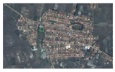
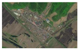
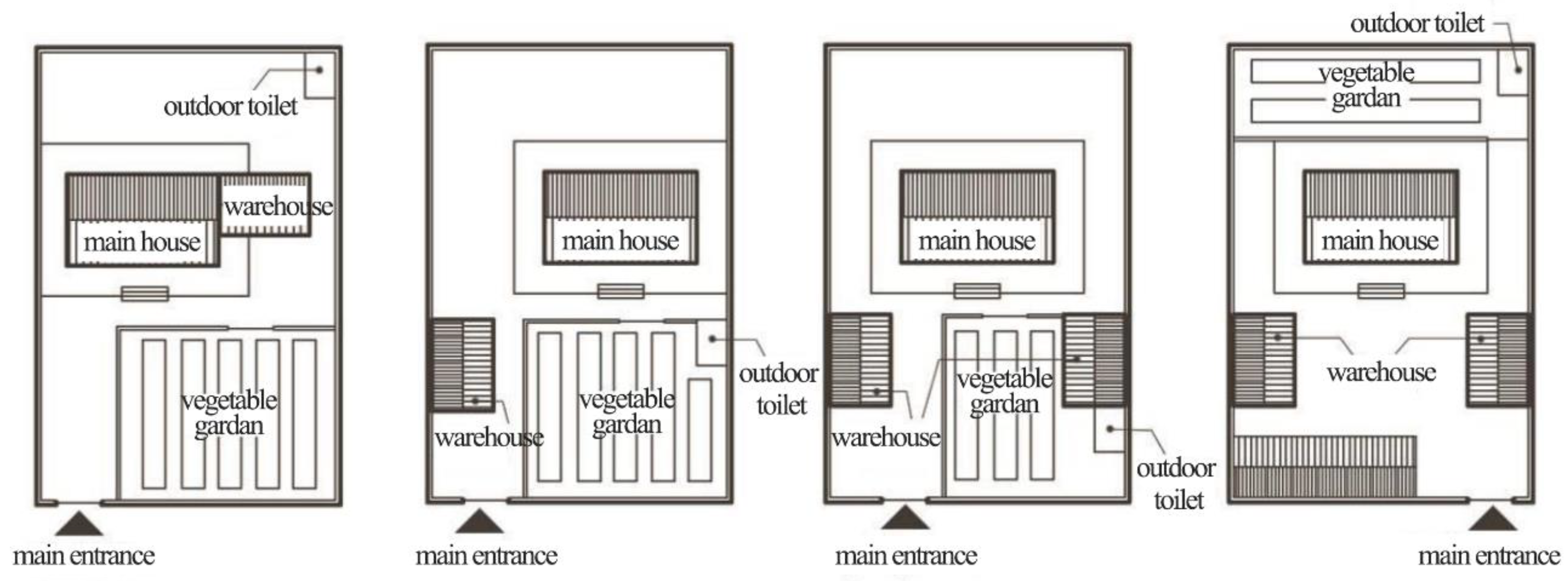
From the above, it is clear that when selecting a research location, it is necessary to comprehensively consider the spatial form of the village and the layout of the buildings within the village. By observing and screening satellite images of villages and towns in the severe cold region of Northeast China, four villages in the cold part of Northeast China were selected as research objects, namely, Xin’an Village, Hailin City, Heilongjiang Province; Chatiao Village, Shimen Town, Antu County, Jilin Province; Qijia Town, Changchun City, Jilin Province; and Xinglongtai Village, Kaiyuan City, Liaoning Province. As shown in
Table 1, the chosen villages and towns are representative in terms of the spatial form and architectural layout in field research. Numerical simulation methods and CFD (Computational Fluid Dynamics) simulation technology can be adopted to achieve this and more directly observe and analyze wind flow characteristics between buildings [
2]. With the rapid development and promotion of CFD technology, computational wind engineering has become an important global research field, and the research object has changed from a simple single building to a complex and changeable group building. Chang et al. applied Fluent 6.3 software to conduct a numerical simulation of vortex concentration in street canyons during the parallel layout of buildings. They studied the relationship between the change in the ratio of street width to building height and vortex formation [
8]. Omar S. Asfoury [
9] used CFD software (Gambit 2.2 and Fluent 6.3) to simulate and analyze the outdoor wind environment under six different building layout forms and simulated and investigated the influence of different wind directions on the wind environment of building groups under the same layout form when the wind direction was 0°, 45°, and 90°. The research results show that building layout form and wind direction angle greatly influence wind speed distribution and wind pressure in building groups [
9].
In summary, most of the experimental and simulation studies on the wind environment both in China and at an international level focus on urban residential areas, and the analysis of the wind environment of village and town courtyards at the micro level (building layout, wall height, etc.) has not been conducted. China has not yet devised a design system or corresponding norms for studying the village wind environment. Nonetheless, the increasingly prominent importance of the village wind environment has aroused our attention. Therefore, the simulation analysis and evaluation of the courtyard wind environment should be carried out in the early stage of village planning. In our preliminary work, numerical simulations of the winter wind environments, analyzed and evaluated for the four typical yard layouts, were carried out based on field research, visits, measurements, and analyses [
10]. This article proposes improved design strategies based on a questionnaire survey and objective testing analysis of courtyard environments in the severely cold regions of Northeast China, followed by simulation and analysis of the courtyard wind environment under different conditions using Fluent 6.3 fluid analysis software. This research provides a theoretical foundation for studying the village courtyard wind environment at the micro level.
3. Numerical Modeling Methods for Wind Environment
The calculation model of the outdoor wind environment in buildings is a three-dimensional geometric model established based on the actual size of the building. The analysis of individual buildings or building clusters requires consideration of the influence of surrounding buildings on their airflow distribution. To reduce computation and accelerate convergence, it is often necessary to reasonably simplify the computational model of actual buildings.
The green building design standards (DB11/938-2012) specify the reproduction area of the model: the target building boundary H (building height) should be reproduced with maximum detail requirements. The convex and concave parts of the building should be simplified as much as possible without affecting the distribution of the surrounding flow field, especially in the distribution of curved or inclined buildings. Simplification of the model is significant. For example, small bumps in buildings are often ignored in calculations, and buildings that approximate a cube shape are simplified as cubes with regular shapes [
26].
3.1. Methodology for Software
Based on domestic and international research on applying and validating numerical simulation software for wind environments and the various comparative analyses, Fluent 6.3 software was chosen in this study as the numerical simulation software (solver) for wind environments and Gambit 2.2 software as the modeling software (pre-processing). After construction of the 3D model using AutoCAD, the model was imported into the Gambit pre-processor for grid division. Gambit’s mesh generation tool is highly automated and can automatically generate structured, unstructured, multi-block, or hybrid meshes [
2]. Tecplot 360 EX 2018 R1 software is the latest data processing software [
27].
As a solver, Fluent 6.3 software must perform preliminary work in Gambit 2.2 software before solving. After formulating a reasonable plan based on physical conditions, data are input into Fluent to find a solution. The following is an introduction to the solution steps: (a) Create geometric models, which can be created in Gambit 2.2 software or imported into CAD files; (b) use Gambit 2.2 software to partition model grids; (c) import the geometric model that completes mesh division and boundary condition setting in the Gambit 2.2 software into the Fluent 6.3 software, in either 2D or 3D; (d) choose the equation required for solving: laminar or turbulent flow; (e) set boundary conditions and types for the calculation area and buildings; (f) set up solution methods and determine parameters; (g) determine the number of calculations and perform the calculations; and (h) export and save simulation result images and other related tasks.
3.2. Simplification of the Model
Mathematical model: The flow of outdoor wind in buildings is generally a form of incompressible, low-speed turbulence. The selection of turbulence models is one of the essential tasks in wind environment simulation. CFD software usually comes with various turbulence models, including algebraic models, one-equation models, two-equation models, and Reynolds stress turbulence models. Some even include extensive eddy simulations. The second equation, the k-ε model, is the most widely used for engineering applications. It suits flows with high Reynolds numbers, low vorticity, and weak buoyancy. Its computational cost is low, with minor fluctuations and high accuracy in numerical calculations. However, the dissipation of the standard k-ε model is too strong. As a result, many modified k-ε models have emerged, such as the RNG k-ε model and realizable k-ε model. Ma Jian et al. [
28] found that the values calculated using the RNG k-ε turbulence model are more significant in the corner area of the blunt body flow. Nonetheless, the distribution of the wind speed ratio and the calculated values in the leeward negative pressure area of the entire calculation area are closer to the experimental values. Compared with the wind tunnel test values, the numerical calculation values using the RNG k-ε turbulence model show that the separation area at the corner of the building is more extensive, and the negative pressure area on the leeward side matches well and better overall. The RNG k-ε model in Fluent 6.3 software, i.e., the improved k-ε model, was selected. By comparing the numerical calculation results of wind pressure with the measured values in the field, the RNG k-ε numerical prediction of this model is better, which reflects the complex flow characteristics of the wind around a typical blunt structure [
29,
30].
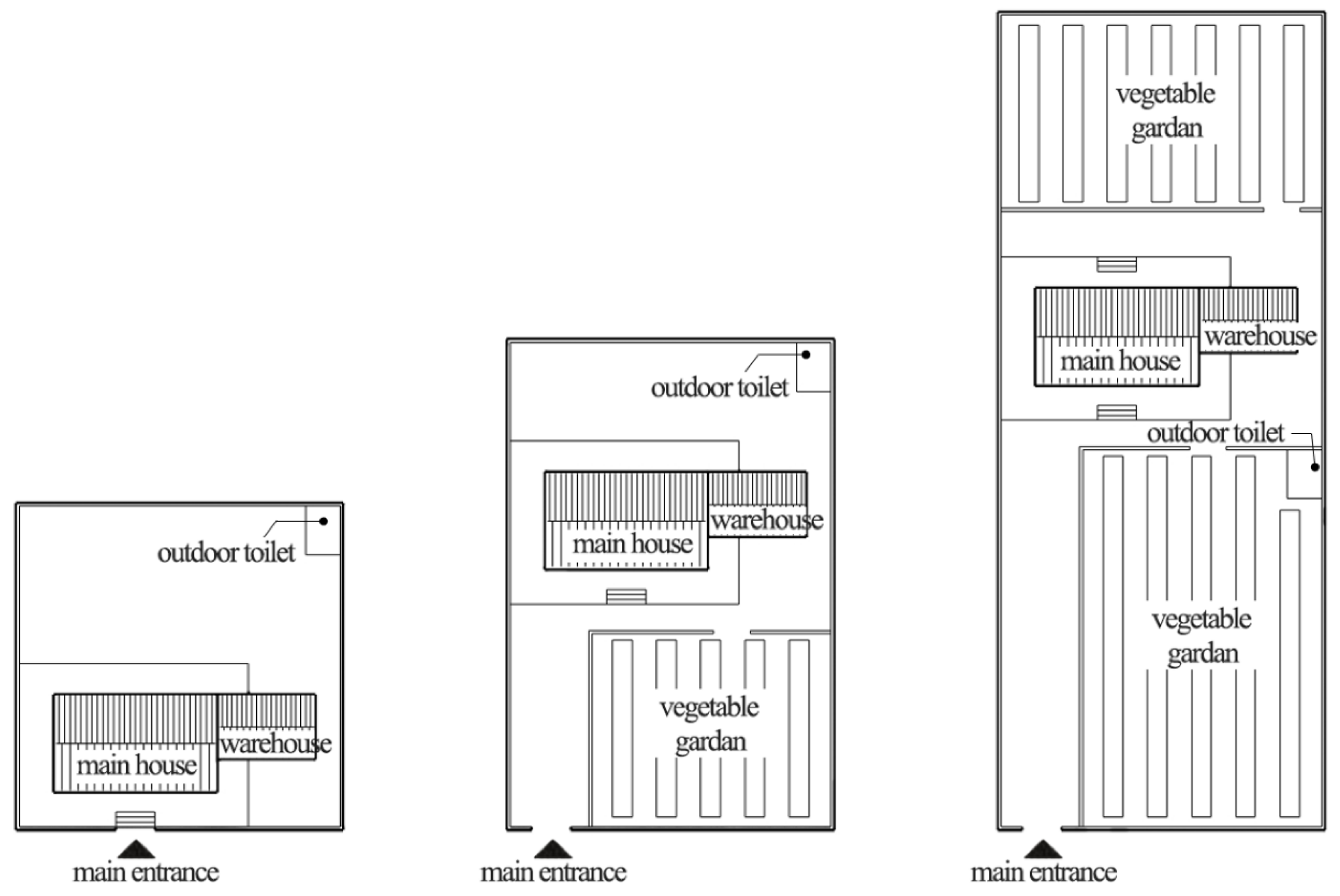
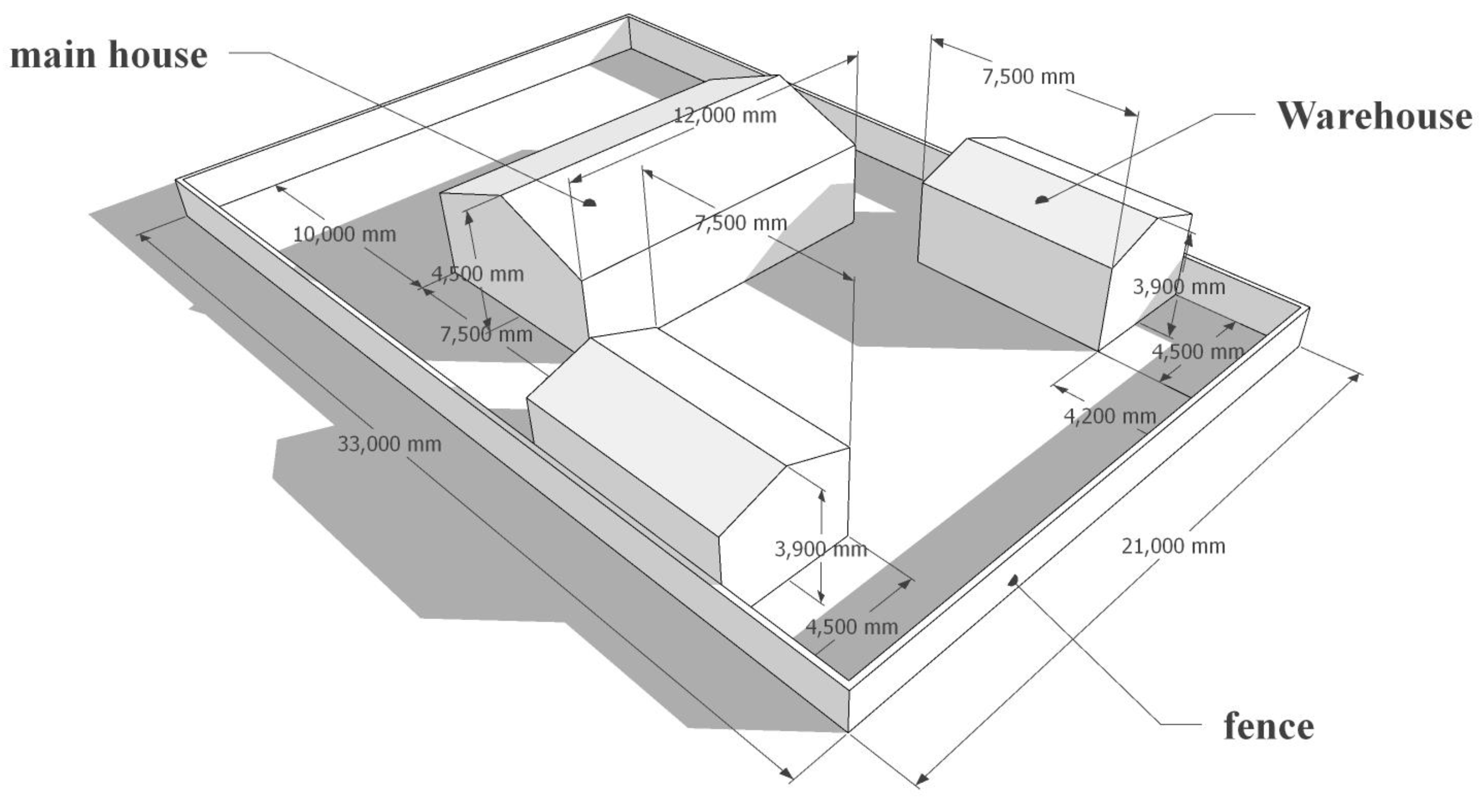
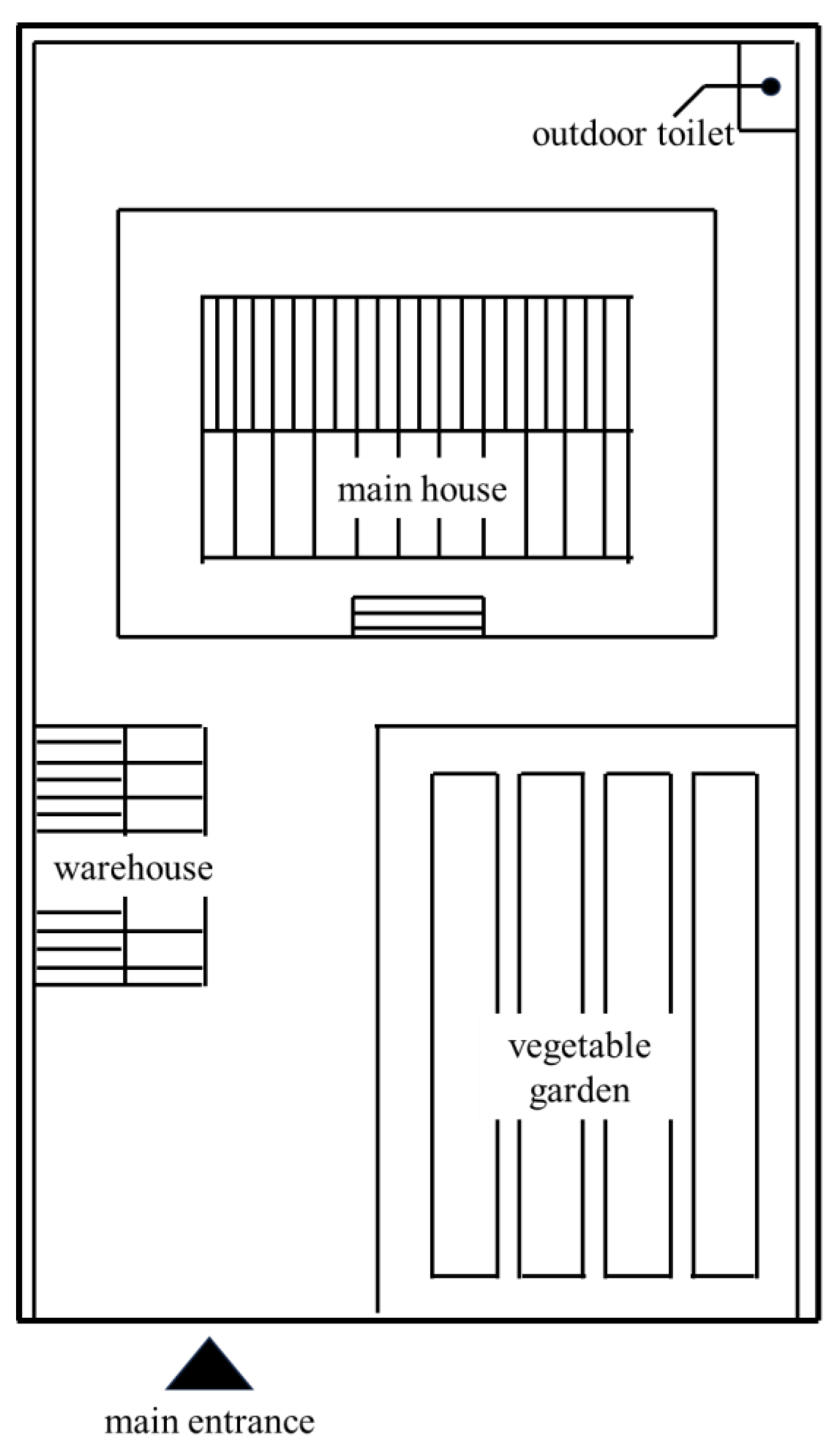
Geometric model: The geometric model used in the simulation was simplified according to the survey results, keeping only the main house, the barn, and the perimeter wall [
31]. The dimensions of the main house are 6 m (width) × 10 m (length) × 4.5 m (height). The dimensions of the barn are 4 m (width) × 6 m (length) × 4 m (height), and the height of the perimeter wall is 1.5 m, as shown in
Figure 4. Since the height of the vegetable garden plants is less than 1.5 m, the vegetable garden has little effect on the pedestrian height wind speed and is negligible. The outdoor toilet is small, so has no significant effect on wind speed and can also be omitted. To reduce the impact of the boundary conditions of the simulation area on the building, an open outdoor space close to the atmosphere is created in the simulation area. The windward direction of the wind field is set to 5 times the length of the site, the downwind direction is set to 10 times the length of the site, and the height of the wind field is set to 5 times the height of the building.
Grid generation: The size and type of the computational grid directly affect the accuracy of simulation results. Because most rural residential buildings use sloping roofs, the geometric models of courtyards and buildings combine triangles and rectangles. Therefore, various triangular and rectangular grids are chosen for the grid type. When dividing the surface grid, triangular grids are chosen, and when dividing the volume grid, a combination of triangles and rectangles is chosen. To reduce the number of grids, the grid is refined into dense and necessary parts to achieve good computational convergence. Due to the focus on studying the wind environment around buildings, a grid division method from lush to sparse was adopted from the building walls to the edges of the simulated area.
3.3. Boundary Condition Setting
Numerical simulation of the wind environment using Fluent 6.3 software requires defining three types of boundaries: velocity inlet, pressure outlet, and wall [
32,
33].
Velocity inlet: Under unstable atmospheric conditions, the flow of air near the surface is affected by the frictional effects of terrain undulations and building distribution, forming a vertically distributed velocity profile for the average wind speed. The closer to the ground surface, the smaller the wind speed. Generally, the range affected by surface roughness is referred to as the atmospheric boundary layer or mixed layer, and atmospheric stability significantly impacts atmospheric diffusion and pollutant transport in the wind field. Generally speaking, a more straightforward exponential or logarithmic profile can represent the distribution of the average velocity’s vertical wind direction [
34]. This study mainly concerns winter wind environment simulation, so the wind direction is northwest wind, the wind speed is 3.57 m/s, the
X-axis direction is 1, and the
Y-axis direction is −1 in terms of orthogonal decomposition.
Pressure outlet: European COST [
35] suggests using open boundary conditions behind obstacles, usually outflow or static pressure boundary conditions. Under the outflow boundary condition, all variables’ derivatives are zero, corresponding to a fully developed flow. For the LES model, convective outflow boundary conditions should be used [
36]. Japanese AIJ [
37] considers zero gradients of all variables as the outflow boundary condition. The outflow boundary should be placed where the impact on the building can be negligible. Therefore, the outlet boundary is usually set to free flow, and the flow on the outlet surface is fully developed and returned to normal flow without building obstacles. The outlet pressure is set to atmospheric pressure. The cross-section at the outlet is taken at the location without reflux, and the pressure outlet boundary condition is used. Pressure outlet boundary conditions can be an excellent solution to the reflux outlet’s convergence difficulties; the airflow intensity is set to a 2% viscosity ratio of 5.
Wall conditions: The setting of top and side boundary conditions is crucial for maintaining a balanced boundary layer distribution, and it is generally believed that the boundary layer is subjected to constant shear stress. This is because the distance between the building’s top, left, and right sides is far enough, and the airflow is almost unaffected by the building, which can be considered a free-sliding surface. Usually, the inflow velocity and turbulence parameters are specified along the entire top boundary at the top of the computational domain [
38]. The setting of the left and right boundary conditions is such that, when the flow direction is parallel to the side boundary, a symmetric limit is usually used to make the velocity component of the parallel flow in the average direction of the zero border. The symmetric boundary condition strengthens a parallel flow by forcing the standard velocity component to be zero, specifying that all other variables’ derivatives are zero [
39]. Japanese AIJ [
37] believes that if the size of the computational domain is large enough, the lateral and top boundary conditions do not significantly impact the calculation results around the target building. A non-sticky wall state (usually with a zero velocity component and tangential velocity gradient) and a larger computational domain will stabilize the calculation process. The building surface and the ground are selected as a no-slip condition, and the average direction of the wind speed value is set to 0 [
9,
40].
4. Results and Discussion
4.1. Wind Pressure and Wind Speed Analysis of Different Courtyard Layout Forms
By comparing the wind speed and wind pressure diagrams of the courtyards with different layouts, it can be seen that the wind speed outside the courtyard is higher than that inside the courtyard, and the difference in the wind speed distribution of courtyards with different layout forms is evident.
The wind shadow zone (i.e., negative pressure zone) is ideal for summer in hot, dry areas and outdoor activities in cold, non-humid areas. In cold regions, winter cold airflow is blocked by buildings in the upwind direction, the wind speed is attenuated in the wind shadow area, and the sunlight is abundant [
41]. Therefore, the downwind outdoor space is ideal for people to escape the cold winter airflow. It can be seen that the location of the wind shadow area is more suitable for small and medium-sized courtyards in cold regions, and it can provide local residents with better outdoor activity space. Differences in enclosures and courtyard structures can result in significant differences in the magnitude of wind speeds within courtyards of different sizes [
42].
Figure 5A,B show the wind speed and wind pressure distribution diagrams of the courtyard with a horizontal layout, respectively. The wind speed ratio is 1.04. The high-value area for wind speed is on the windward side between the main house and the fence. The wind shadow area is mainly on the leeward side of the main house, with a wind speed ratio of 0.17, and the site is approximately three-quarters of the total building area. A corner wind is formed at the southwest corner of the main house, with a high wind speed value and a wind speed ratio of 1.15. The increased weight of wind pressure is distributed on the windward side of the building, which easily causes the penetration of the cold wind. The airtightness and the thermal insulation design should be strengthened for the windows and doors on the windward side of the main house [
43].
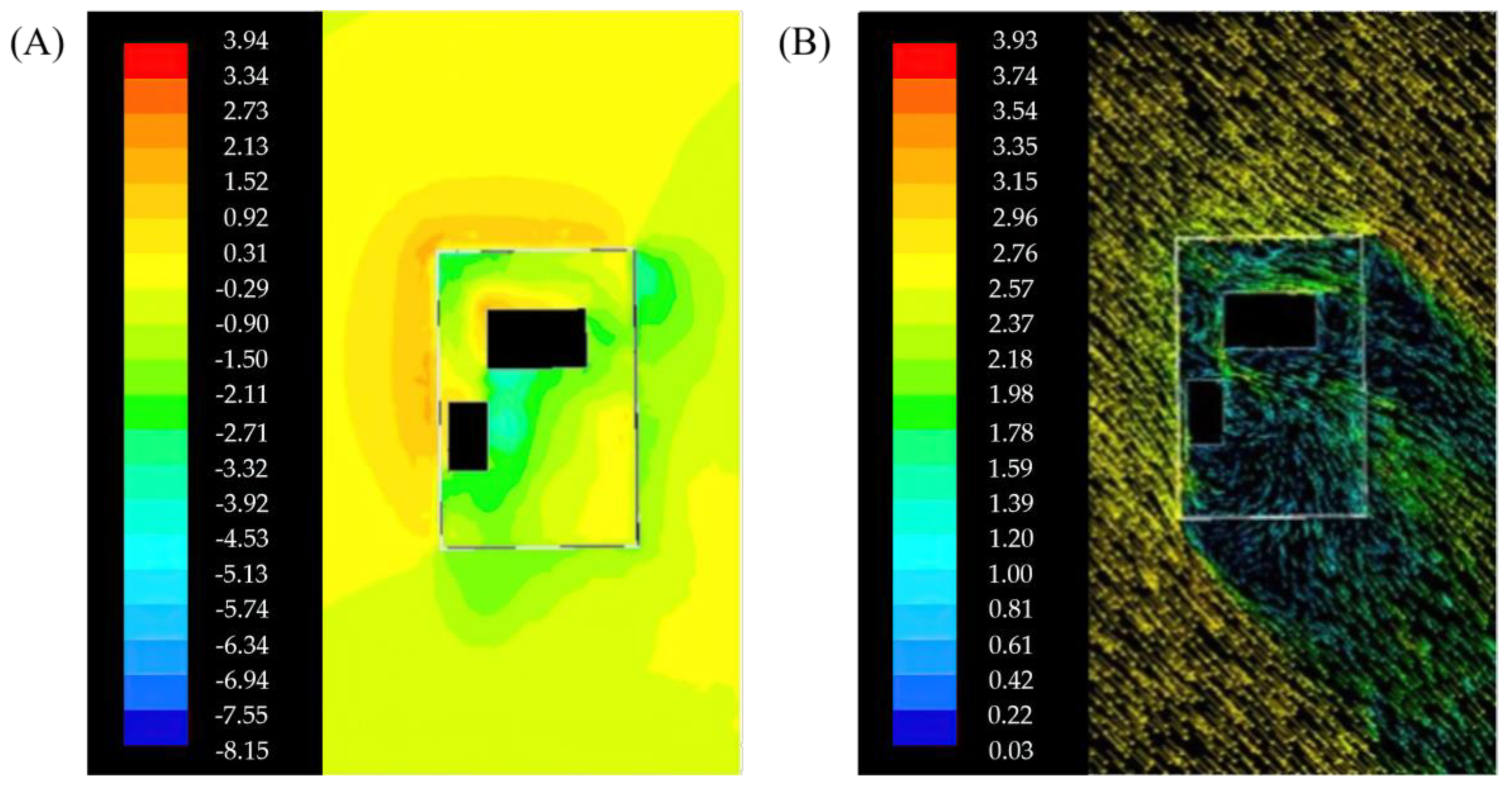
Figure 6A,B show the wind speed and wind pressure distribution diagrams of the “L” − shape layout (the barn is perpendicular to the left side of the main house). The wind speed ratio is 0.98. The high-value area for wind speed is the windward side between the main house and the fence. The wind shadow area is mainly located on the leeward side of the main house and warehouse. The wind speed ratio in the wind shadow area is 0.12, and the site is approximately 1.5 times the total building area. A corner wind is formed at the southwest corner of the main house, with a high wind speed value, and the wind speed ratio is 1.02, accompanied by a low-speed vortex. The increased weight of wind pressure is distributed in the northwest corner of the main house, which easily causes the penetration of cold wind. The airtightness and the thermal insulation design of the doors and windows on both sides of the northwest corner wall of the main house should be strengthened.
Figure 7A,B show the wind speed and wind pressure distribution diagrams of the “U” − shape layout. The northeast corner of the main room forms a corner wind. The wind speed ratio is 1.11. Due to the design of the shape, the degree of enclosure increases, and the wind shadow area is located on the building’s downwind side and both sides of the barn. The wind speed ratio in the wind shadow area is 0.09, and the site is approximately two times the total building area, accompanied by a low-speed vortex. The high value of wind pressure is distributed on the windward side of the main house, which easily causes cold wind infiltration. The airtightness and the thermal insulation design for the windows and doors on the windward side of the main house should be strengthened.
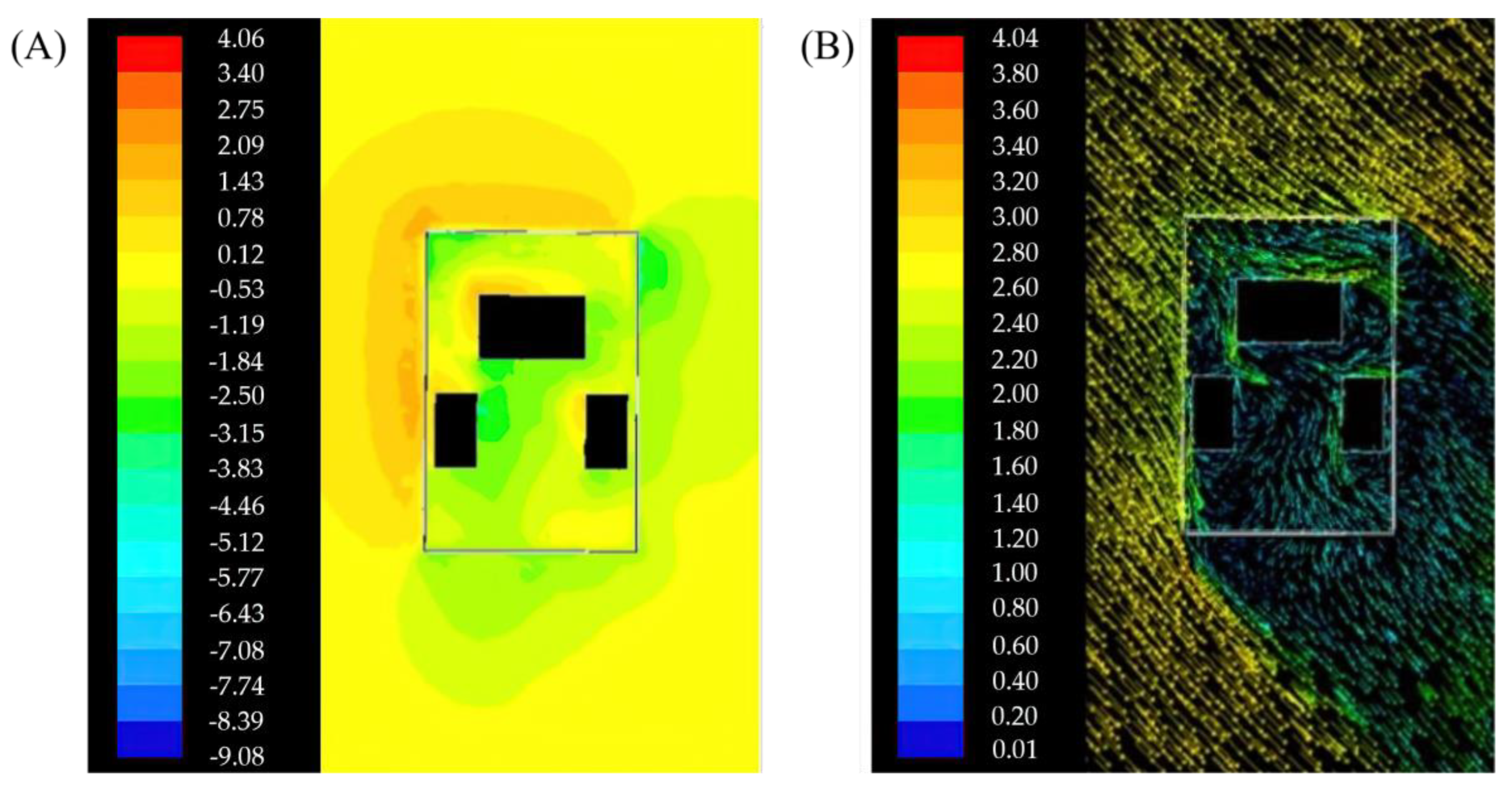
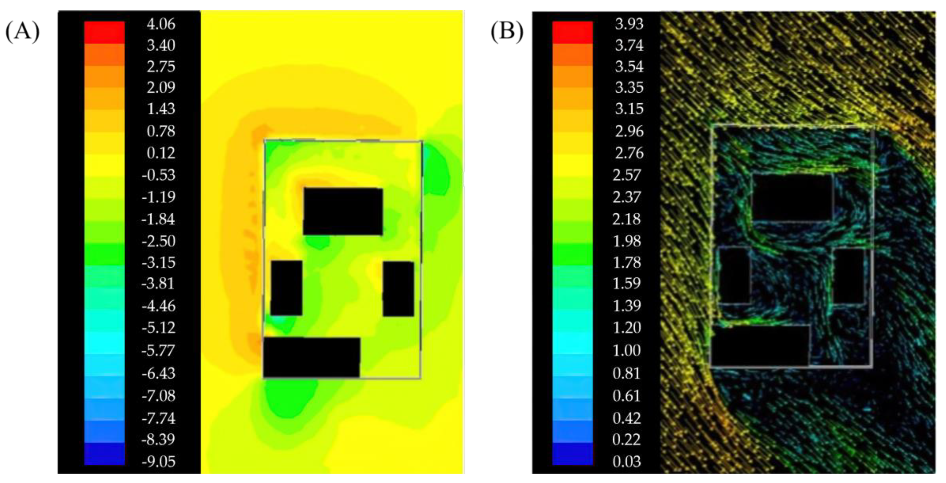
Figure 8A,B show the wind speed and wind pressure distributions in the square layout, respectively. The location of the main room weakened its role in blocking the wind. Wind speed is more significant, and the wind speed ratio is 1.06. The high-value area for wind speed is on the windward side between the main house and the fence. The wind shadow area is mainly located on the leeward side of the main house. The wind shadow area’s wind speed ratio is 0.08, and the site is approximately 1.25 times the total building area. The spatial distance between the right warehouse’s main room and corridor is relatively close, forming a narrow tube effect of wind. The wind speed ratio is 0.97, and is accompanied by a low-speed vortex. The high value of wind pressure is distributed on the windward side of the main house, which easily causes cold wind infiltration. The airtightness and the thermal insulation design for the windows and doors on the windward side of the main house should be strengthened. It is also necessary to install windproof measures such as green plants in the central walkway between the main house and the warehouse in the courtyard.
From the above, the area of the wind shadow zone also varies with the degree of building enclosure. The size of the wind shadow zone of the horizontal − type courtyard accounts for about 59% of the total area, and the negative pressure area mainly appears in the northwest corner of the enclosure wall and the southwest corner of the building. The “L” − shaped courtyard wind shadow zone accounts for about 82% of the total area; the negative pressure area mainly appears in the northwest corner of the wall, the main house, the southwest corner of the building, and the southwest corner. The “U” − shape courtyard wind shadow area accounts for about 81% of the total area; the negative pressure area appears mainly in the northwest corner of the enclosure wall, the main room, and the barn corner. The wind shadow area of the square − type courtyard accounts for about 83% of the total area, and the negative pressure area mainly appears at the northwest corner of the fence wall, the southwest corner of the main house, and the south side of the mountain wall of the barn. It can be seen that the area of the wind shadow zone is mainly affected by the buildings on the windward side and is not affected by the degree of enclosure of the buildings. There is no obvious pattern of pressure variation in the negative pressure zone. In the process of transitioning from a horizontal courtyard to an “L” − shape courtyard, the pressure in the negative pressure area decreases with the increase in enclosure degree, and the size of the low-pressure area (blue area) in the “L” − shape courtyard significantly increases compared to that in a horizontal courtyard. In the process of transforming from an “L” − shape courtyard to a “U” − shape courtyard, the pressure in the negative pressure area significantly increases, and the pressure in the negative pressure area of the “U” − shape courtyard is higher than that of the horizontal courtyard. The negative pressure zone pressure of enclosed courtyards is similar to that of enclosed courtyards. Therefore, the wind pressure inside the courtyard is unrelated to the degree of building enclosure.
The degrees of enclosure of the courtyard and the size of its internal wind speed have some differences. The horizontal − type courtyard on the west side of the building wall is positioned to form a high-speed wind band. A low-speed vortex appears in the front of the building and the east side of the wall. “L,” − “U,” − and square − shaped courtyards only show high-speed airflow at the corners of the windward side of the building, and a low-speed vortex appears on the downwind side of the building. As the degree of enclosure of the building increases, a low-speed vortex can more easily be generated inside the building. As shown in
Figure 8, a large-area vortex is formed inside the square − courtyard.
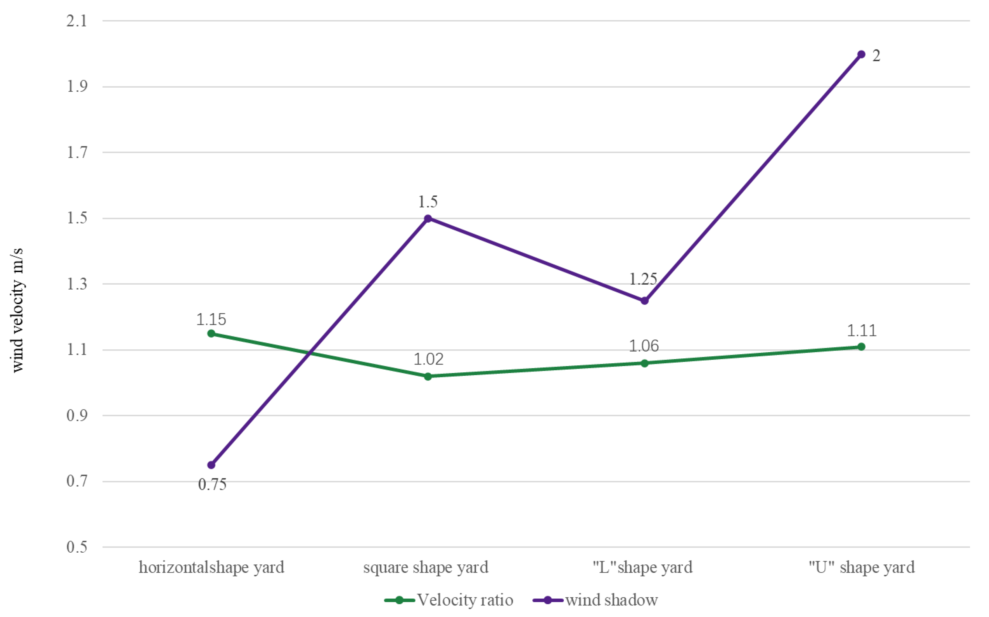
As shown in
Figure 9, the wind environment is ranked according to the maximum wind speed ratio and the area of the wind shadow area as follows: square − type layout > “L” − shape layout > “U” − shape layout > horizontal − type layout.
4.2. Layout Optimization Strategy of Village Courtyard Wind Environment Improvement
It can be seen from the simulation analysis results that the courtyard shape significantly impacts the courtyard wind environment, so the form and scale of the courtyard should be limited to a certain extent during the optimization design of the courtyard wind environment. In the colder areas, the broader enclosures could increase the receipt of sunshine and block the cold winter winds by virtue of the surrounding buildings and walls. The main optimization methods are as follows:
- (a)
It is suggested that when planning and designing new courtyards, the aspect ratio of the courtyards should be controlled within the range of 2:1, and the shape should be rectangular to avoid the appearance of bar-shaped courtyards, under the condition of satisfying the functional integrity of the courtyards.
- (b)
In renovating existing courtyards, strip courtyards and more extensive courtyards can be subdivided, achieving the economical use of land and effectively controlling the wind environment in the courtyards. Consanguinity and kinship networks are an essential element in the rural residential system in the historical development of Chinese society. Considering the practical problems of housing in villages and towns, it is suggested that the existing strip courtyards or enlarged courtyards should be arranged as the original courtyards by adding houses or, when the children get married and build houses independently, to change the strip courtyards into two square or rectangular courtyards.
- (c)
For existing courtyards with no additional construction plan, it is suggested to divide the original strip courtyards by walls and tall plants and try to ensure that the aspect ratio of each space in the courtyards after division is controlled within the range of 2:1.
The enclosing form and placement of buildings in the courtyard obviously influence the courtyard’s wind environment. Among these factors, the state of the building enclosure greatly influences the area ratio of the low-speed vortex area in the courtyard’s internal wind environment, and the building placement directly affects the generation of a high-speed wind zone in the courtyard. The wind environment optimization design of the courtyard layout should be carried out according to these simulation results and combined with the actual situation of the existing village courtyard in the cold area.
From the perspective of the overall wind environment characteristics in cold regions, the following recommendations can be made. First, regarding the degree of building enclosure, it is recommended to choose the “L” − and “U” − shapes of the building layout. Secondly, the distance between the building and the wall on the north windward side should be controlled between 6 and 10 m to ensure the maximum wind shadow area, and to reduce the wind speed of the high-speed wind belt and the size of the wind speed change of more than 70% within 2 m. The detailed strategy is as follows:
- (a)
Considering the location of the house in the courtyard, the courtyard should adopt the layout having front and back yards. At this time, a good wind environment can be formed inside the courtyard, and the wind shadow area is relatively large, which is conducive to reducing the impact of cold wind on the building and outdoor environment in winter. However, some courtyards will be limited in the actual design due to the constraints of the village’s overall planning, traditional living habits, design standards, and other factors.
- (b)
From the perspective of the degree of building enclosure, the courtyard should choose an “L” − shape or “U” − shape layout and control the wind environment of the courtyard in winter through the enclosure of the building. However, the degree of enclosure should not be too high, which can easily cause low-speed eddy currents inside the courtyard, resulting in problems such as snow accumulation in winter and poor ventilation in summer. The vertical distance between the wall on the windward side and the building should be controlled between 6 and 10 m to ensure comfort and a large wind shadow area, and to reduce the apparent high-speed wind belt formed by the courtyard on the windward side in winter and the site where the wind speed changes by more than 70% within 2 m. If the annual wind speed is not significant, the horizontal layout form can also be chosen so that the summer courtyard and the interior of the building can also have an excellent natural ventilation effect.
- (c)
For the renovation design of existing courtyards, targeted improvements should be made according to the main problems existing in the current courtyards. If the house is not correctly positioned in the courtyard, it can be improved by adding houses or green plants. If the problem is caused by improper building layout, it can be solved by increasing or removing the reasonable arrangement of houses, firewood stacks, or grain stacks.
4.3. The Improvement Scheme of the Village Courtyard Wind Environment Improvement
According to the previous simulation analysis and wind environment improvement design strategy, taking the area where the dominant wind direction in winter is a northwest wind and the prevailing wind direction in summer is a southerly wind as an example, the comprehensive design of village courtyards was carried out to take into account the problems of wind prevention in winter and ventilation in summer. Taking a courtyard as an example, the selection of parameters such as courtyard shape, building layout, wall height, and material is within the appropriate range of the above improvement design strategy. The specific scheme is as follows: The shape of the courtyard is set as a rectangular courtyard with a length–width ratio of 5:3. The main buildings in the courtyard include the main room and the warehouse. The warehouse is arranged vertically with the main room and is located on the left side of the main room in the form of an “L” layout. The vertical distance between the main house and the wall on the windward side of the dominant wind direction in winter is 6 m. The height of the fence is set to 1.6 m. The specific design scheme is shown in
Figure 10.
5. Conclusions
Based on the survey data statistics, this paper divides the courtyard into horizontal-type courtyards, “L” − shaped courtyards, “U” − shaped courtyards, and square-type courtyards according to the degree of building enclosure. Then, the courtyards under different classifications are simulated and analyzed in terms of the two aspects of wind pressure and wind speed. The analysis results show that the wind environment of different layout forms of courtyards has advantages and disadvantages; the smaller the scale, the smaller the wind speed in the courtyard, that is, for the square courtyard and the small and medium-sized rectangular courtyard. The wind speed in the courtyard is small, and the large-scale strip courtyard makes it easy to produce high-speed wind belts. The higher the degree of enclosure of the building, the smaller the wind speed in the courtyard; that is, the “L” − shape, “U” − shape, and square − type courtyards are smaller than the horizontal − shape courtyard, but the higher the degree of enclosure, the more easily low-speed eddy currents are produced inside the courtyard and the greater the number of low-speed eddy current areas in the square-type courtyard. Through the simulation analysis of different layout forms of courtyards, it can be found that they have certain advantages and disadvantages regarding the influence of the courtyard wind environment. Through the numerical simulation and statistical results of the wind environment, it can be seen that the courtyard’s different layout forms directly affect the wind speed size in the wind shadow zone. The wind environment of the courtyard with the “U” − and “L” − shaped layouts is better than that of the courtyard with the horizontal − shaped layout. This leads us to the following conclusions:
- (a)
The higher the degree of building enclosure on the windward side, the lower the wind speed value in the site. According to the characteristics of wind flow, when buildings block it, a high-speed airflow is formed at the corner of the windward side of the building, but the blocking of the wind by the structure is only effective within a specific range. The size of the wind speed attenuation area is generally related to the length, width, and height of the structure and is also affected by the spacing of the system. According to the simulation analysis results of wind speed, it can be found that with the increase in building enclosure degree, the intensity of wind speed attenuation in the courtyard is greater. However, the low-speed eddy current is easily generated inside the courtyard with a high degree of enclosure. The generation of low-speed eddy currents has the most significant influence on the degree of partition of the building. The higher the degree of a section of the building in the courtyard, the more easily low-speed eddy currents can be formed in the courtyard, and the more significant the proportion of the low-speed eddy current areas included in the courtyard.
- (b)
The greater the number of buildings on the windward side, the larger the wind shadow area within the compound. According to the analysis results of
Section 4, the size of the wind shadow area also changes with the different degrees of building enclosure, but there is no obvious rule. It can be seen that the site of the wind shadow area has little influence on the scale of the courtyard and the degree of building enclosure, which is mainly affected by the distance between the upwind building and the wall and the number of upwind buildings.
The method of optimizing the courtyard wind environment should adopt the way of “learning from each other,” that is, optimize the wind environment of different types of courtyards and courtyards facing different kinds of wind environment problems. For the village and town compounds in the severe cold region of Northeast China, the temperature of the cold wind in winter is low, and this cold period lasts for a long time. The wind environment design of the compound should follow the principle of wind protection in winter and ventilation in summer, as it has the most significant impact on the residents’ use of space in the compound. Considering the wind speed, the area of the wind shadow, and the number of vortexes, the wind environment of the square-type compound is the best. This can be used as a reference for the improvement of the wind environment of the compounds of villages and cities, and the design of newly built compounds, in the cold areas of Northeast China.


