Abstract
Additional temperature stresses in continuously welded rails (CWRs) are caused by track/bridge interaction (TBI) due to thermal actions. Exceeding permissible stresses in CWRs on the bridge can lead to track buckling or rail cracking, compromising the safety of railway traffic. The main aim of the conducted study is to determine the effects of the key parameters such as rail cross-sectional area, track longitudinal resistance, bridge expansion length, and longitudinal stiffness of the fixed bridge support on the reduction of additional temperature stresses in CWRs on steel truss railway bridges. To quantify the effects of these parameters, two steel railway bridges with CWRs and the maximum expansion lengths according to UIC Code 774-3 were analyzed: (1) simply supported truss bridge with expansion length of 60 m and (2) continuous truss bridge with expansion lengths of 2 × 60 m. According to the obtained results, the track longitudinal resistance had the most significant impact on additional temperature stresses in CWRs, leading to their reduction of up to 72%. The bridge expansion length and the rail cross-sectional area led to reductions of up to 25% and up to 18%, respectively. Considering the deformation criteria of TBI, the longitudinal stiffness of the fixed bridge support had a minor effect on the reduction of additional temperature stresses in CWRs.
1. Introduction
A track with continuously welded rails (CWRs) offers several advantages compared to a track with mechanical rail joints. These advantages are reflected in a substantial reduction of rolling resistance between the railway vehicle wheels and the rail, resulting in increased speed and improved ride comfort. On the other hand, in the case of track with CWRs, there are no rail gaps that would allow longitudinal temperature expansion of rails, causing temperature stresses. Temperature stresses in CWRs can lead to track buckling during extremely hot summer temperatures or rail cracking in extremely cold winter conditions. Both stress limit states in CWRs directly affect the safety of railway traffic. The issue of railway traffic safety is particularly pronounced on railway bridges, where additional temperature stresses occur in CWRs caused by track/bridge interaction (TBI) due to thermal actions. Equally important from the aspect of railway traffic safety is the early detection and identification of damage to the bridge structure [1].
Climate change can significantly affect the safety and performance of infrastructure systems [2]. The railway infrastructure managers should put in place adequate plans to anticipate and adapt to future climate change [3]. Developed climate change models predict that the Earth’s mean annual temperature will increase by 1 °C to 5.5 °C during the twenty-first century [4]. The existing railway infrastructure, especially the steel railway bridges with CWRs, should be improved in order to become more resistant to the temperature effects, while the new railway infrastructure should be designed according to the upcoming climate change. Researchers and engineers are faced with great challenges in finding adequate technical solutions in bridge engineering [5,6,7,8], as well as reliable assessment and calculation of additional temperature stresses in CWRs on bridges.
The application of elastic rail fastening systems with reduced longitudinal resistance of the rail can affect the reduction of additional temperature stresses in CWRs on the bridge and prevent track buckling during extreme summer temperatures. In addition, the improvement of technical regulation should take into account the impact of climate change, as well as a multidisciplinary approach in the analysis of TBI. This approach implies a synthesis of modern knowledge in the field of railway superstructure, bridge engineering, theory of structures, as well as thermal actions.
Fryba [9] presented an analytical approach to address TBI due to thermal actions, as well as key parameters affecting additional temperature stresses in CWRs on the bridge. To validate the analytical approach, an experimental study was carried out, aiming to determine the permissible expansion lengths of steel railway bridges. The main drawback of the study was the application of the linear formulation of TBI due to thermal actions. Ruge and Birk [10] carried out a pioneering analysis of longitudinal forces in CWRs on the bridge, considering the deformation history and nonlinear formulation of TBI. Stiffness formulations were derived for the following load cases: the temperature change in the bridge superstructure and the railway vehicle load. Similarly, in the study carried out by Ruge et al. [11], it was deduced that the additional stresses in CWRs on bridges were primarily influenced by the established coupling interface between the track and bridge in the longitudinal direction. This coupling interface is characterized by nonlinear longitudinal stiffness and exhibits a significant dependence on whether the track is unloaded or loaded. In the research conducted by Luo and Zeng [12], a new variation pattern of the longitudinal resistance of the rail fastening system was presented, considering the load history. This variation pattern was experimentally verified using the Dahl friction model. Also, considering the load history, an algorithm was developed for TBI based on the Ritz method and the principle of minimum potential energy. Zhang et al. [13] analyzed TBI due to thermal actions and railway vehicle load from the aspect of serviceability and safety of the track with CWRs. Laboratory experiments were conducted to determine the exact nonlinear characteristics of rail fastening systems. It was found that the adopted displacement/longitudinal resistance curves of the rail fastening system have a significant impact on the additional stresses in CWRs and the relative longitudinal displacements of the track and bridge. Ryjáček and Vokáč [14] conducted a comprehensive and extensive long-term monitoring study of TBI. Based on their findings, they formulated equations for calculating the nonlinear stiffness of the track-bridge connection. In addition, they analyzed the impact of temperature on the ballast stiffness. In the research conducted by Mirza et al. [15], the effects of thermal actions on the structural behavior of a railway transom bridge were investigated using finite element-based numerical simulations. The findings indicate the presence of nonlinear structural behavior in the bridge components due to very high temperatures. Mubarack and Upadhyay [16] proposed the TBI model for the analysis of track stability of simply supported steel railway bridges due to thermal actions using nonlinear analysis. Their research confirmed that TBI indeed affects the reduction of both the maximum buckling temperature and the safe buckling temperature of the track. Kumar and Upadhyay [17] studied the effect of temperature gradient on the TBI, specifically focusing on bridge support reactions, additional temperature stresses in CWRs, and track stability. The analysis revealed that while the temperature gradient does affect the bridge support reactions, it does not have a significant impact on the stresses in CWRs or track stability. Yun et al. [18] developed a three-dimensional TBI numerical model and carried out a nonlinear analysis to calculate the permissible additional compressive stresses by considering different track conditions. According to the obtained results, it was concluded that the prescribed permissible values of additional compressive stresses should be reduced tracks having relatively small lateral resistance. Strauss et al. [19] presented an alternative method of modeling the connection between the track and bridge based on composite materials. The aim of this study was to use in-situ measurement results to analyze the permissible values of additional stresses in CWRs caused by TBI due to thermal actions. This approach overcomes the disadvantages of the spring model, such as singularities in the stress distributions in CWRs and the inability of changes in the mechanical system induced by thermal actions and railway vehicle load. Diachenko et al. [20] studied the effects of thermal actions and railway vehicle load on the TBI for specific types of bridge structures. The effects of the expansion length, the structural scheme of the bridge, and the longitudinal stiffness of the intermediate bridge supports on the stresses in CWRs were considered. Based on the obtained results, recommendations in terms of measures to reduce stresses in CWRs were given. Salcher et al. [21] analyzed high-speed railway bridges using a stochastic approach to account for uncertainties in the mechanical models of ballasted steel bridges. The impact of seasonal temperature changes on the bridge structure was considered. The results demonstrated in the study were opposite to the results of the traditional code-based design procedure. Mirković et al. [22] studied the possibility of avoiding rail expansion devices on the bridge while at the same time exploiting the maximum permissible stress capacity of the rail profile. A general algorithm for stress reduction due to vehicle/track/bridge interaction was developed, including both the track and bridge parameters, the effects of climate conditions, and the design conditions of the railway route.
From the aspect of technical regulation, the recommendations given in UIC Code 774-3 [23] theoretically explain TBI and define the permissible additional stresses in CWRs on the bridge, as well as the limit longitudinal displacements of the track and bridge. In addition to the theoretical explanations of TBI, the recommendations also provide guidelines for conducting numerical simulations to calculate additional stresses in CWRs on the bridge. The UIC Code 776-2 recommendations [24] define guidelines for the design of railway bridges from the aspect of vehicle/track/bridge interaction. The European Committee for Standardization (CEN) published the standard EN 1991-2 [25], in which the traffic loads for the calculation of railway bridges, as well as for the calculation of TBI, were defined.
Based on the aforementioned studies and technical regulations in the field of TBI, it can be concluded that the calculation of additional temperature stresses in CWRs on the bridge is still a current topic and requires constant improvement from the aspect of research and technical regulation. In addition, there is a need for more detailed guidelines to conduct TBI due to thermal actions with the aim of minimizing additional temperature stresses in CWRs on the bridge. These guidelines should be established through a comprehensive parametric study considering the key track and bridge parameters, such as the rail cross-sectional area, the track longitudinal resistance, the bridge expansion length, and the longitudinal stiffness of the fixed bridge support. The study presented in the paper aims to evaluate the effects of these parameters on additional temperature stresses in CWRs on steel truss railway bridges. Calculation of additional temperature stresses in this study was carried out using numerical analysis based on the finite element method. Section 1 presents an overview of the literature in the field of TBI. In Section 2, TBI due to thermal actions, as well as track and bridge parameters, are theoretically explained. Properties of the numerical models were presented in Section 3, followed by the results and discussion of the performed parametric study in Section 4. The conclusions of the study are presented in Section 5.
2. TBI Due to Thermal Actions
Additional temperature stresses arise as a consequence of TBI. In other words, these stresses arise from temperature changes in the bridge superstructure relative to the bridge reference temperature at which the installation and final welding of CWRs was performed. In the case of a negative temperature change (ΔTN,con) in winter conditions, there is a contraction of the bridge superstructure of length LB and the appearance of additional tensile stresses in CWRs above the roller bridge support (Figure 1a). On the other hand, in the case of a positive temperature change (ΔTN,exp) in summer conditions, there is an expansion of the bridge superstructure and the appearance of additional compressive stresses in CWRs above the roller bridge support (Figure 1b).
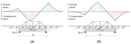
Figure 1.
Diagrams of additional temperature stress in CWRs according to [26,27] due to (a) Negative temperature change in bridge superstructure and (b) Positive temperature change in bridge superstructure.
Temperature changes in the bridge superstructure (ΔTN,con and ΔTN,exp) are determined according to the standard EN 1991-1-5 [28], as well as the national annex SRPS EN 1991-1-5/NA [29]. For simplified calculations, temperature changes in the bridge superstructure equal to ΔTN,exp = ΔTN,con = ±35 °C can be adopted according to [25]. Figure 2 shows the relation between the components of the minimum/maximum shade air temperature (Ta,min, Ta,max) and the minimum/maximum uniform bridge temperature (Te,min, Te,max) for steel (truss) railway bridges.
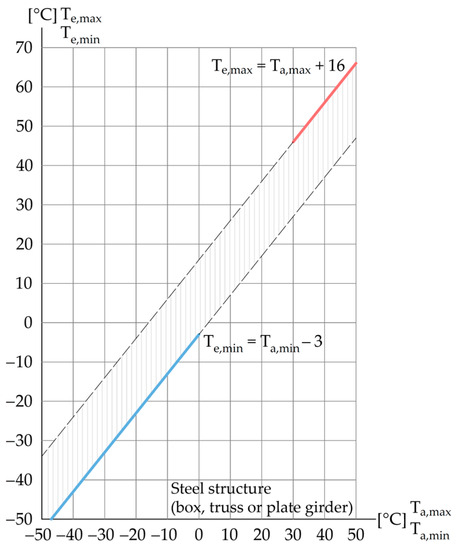
Figure 2.
Diagrams of minimum/maximum uniform bridge temperature according to [28].
The relevant temperature changes for the calculation of the maximum contraction/expansion of the bridge superstructure are determined using the following formulas [28]:
The initial bridge temperature (T0) should be taken as the temperature of the bridge structure at the relevant stage of its completion of construction or as the average temperature during the bridge construction period. In case the information is not available during the bridge construction period, the value of T0 = 10 °C can be adopted according to [28,29].
For more detailed calculations of additional temperature stresses in CWRs on the bridge, the spatial-temporal temperature distribution in the structural members of the bridge superstructure should be taken into account. This temperature distribution is uneven and depends on air temperature, solar radiation, and other weather conditions, as well as on the orientation of the bridge, its geometric and material properties, and its surroundings [30]. Temperature mapping for a long-span steel truss arch bridge based on field monitoring data was presented in [31]. This approach leads to a more accurate estimation of the temperature extremes in the bridge superstructure, which is of fundamental importance for the design and maintenance of bridges. Similarly, in [32], a methodology for accurate mapping of the bridge temperature response based on the spatial distribution of temperature in the bridge superstructure and the properties of the bridge bearings was presented. Accordingly, it was shown that the temperature expansion/contraction of the bridge superstructure significantly depends on the properties of the bridge bearings. On the other hand, in the case of extreme winter conditions, the method presented in the study [33] can be applied for remote monitoring of bridge temperatures.
The uneven bridge temperature distribution and non-uniform expansion/contraction of the bridge superstructure can affect the redistribution of additional temperature stresses in CWRs on the bridge. However, the effects of TBI are still not completely understood due to the uncertain properties of the ballasted track. For this reason, the effects of TBI should be investigated and experimentally verified. In the study [34], quantification of the TBI due to thermal actions was carried out through field measurements. The measurement system was developed considering the track and bridge parameters that affect the TBI due to thermal actions. In addition, numerical analysis was carried out, and the results were compared with the measured data.
Uneven temperature distribution and temperature stresses in CWRs can be efficiently determined using the methodology presented in [35], which is based on the measurement of rail surface temperatures and numerical coupled thermal stress analysis.
In the following, the track and bridge parameters that affect additional temperature stresses in CWRs on the bridge and their basic properties are briefly presented. These parameters are defined in [23] and detailed explained in [36,37].
2.1. Track Parameters
According to [23], the track parameters are:
- Rail cross-sectional area;
- Track longitudinal resistance.
Modification of the track parameters can substantially affect the results of the TBI analysis in terms of the reduction of additional temperature stresses in CWRs on the bridge. Such an approach is in line with engineering practice during the reconstruction of railway superstructure on bridges.
Table 1 shows the geometric properties of the selected Vignole’s rail profiles used in this study. Material properties of the rail steel are defined according to EN 13674-1 [38].

Table 1.
Geometric properties of the Vignole’s rail profiles 60E1, 54E2, and 49E1 according to [38].
The track longitudinal resistance defines the connection between the track and the bridge structure. Figure 3 shows diagrams of track longitudinal resistance as a function of the relative displacement of CWRs in relation to the sleeper, i.e., the relative displacement of the sleeper through the ballast, both for unloaded and loaded tracks. The shape of the diagrams is bilinear, where the track longitudinal resistance increases up to the limit value of the relative displacement, after which it is kept constant [23].
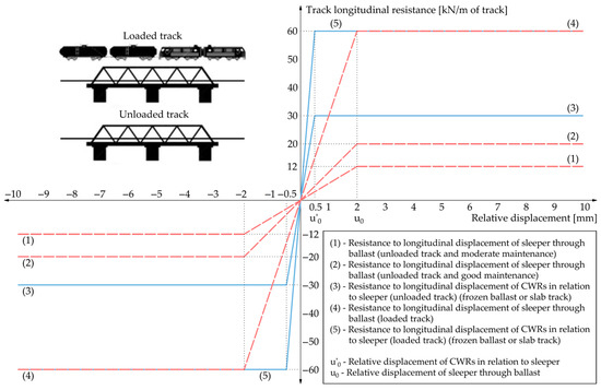
Figure 3.
Diagrams of track longitudinal resistance according to [23,37].
2.2. Bridge Parameters
According to [23], the bridge parameters are:
- Bridge expansion length;
- Bridge span;
- Longitudinal stiffness of bridge support;
- Bending stiffness of bridge superstructure;
- Height of bridge superstructure.
Modification of the bridge parameters leads to structural changes in the bridge that can affect the reduction of additional temperature stresses in CWRs on the bridge. In the subsequent analysis, only the bridge expansion length and the longitudinal stiffness of the bridge support will be considered as they affect the TBI due to thermal actions.
The bridge expansion length (LT) represents the distance between the thermal center point and the end of the bridge structure (Figure 4). The position of the thermal center point depends on the position and type of bridge supports [23]. The maximum expansion length of steel railway bridges with CWRs without the rail expansion device (which should be checked in TBI analysis) is 60 m [23]. Consequently, the maximum length of the bridge structure with fixed support in the middle of the structure can be up to 120 m.
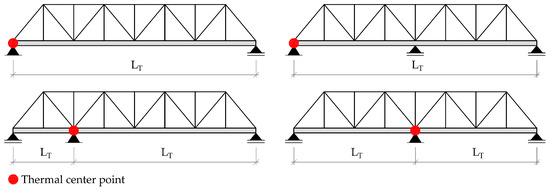
Figure 4.
Examples of bridge expansion lengths of different structural systems according to [23].
The longitudinal stiffness of the bridge support (K) considers the combined stiffness of the bearing, pier, foundation, and foundation soil (Figure 5). In general, only the longitudinal stiffness of the fixed bridge support should be considered. The longitudinal stiffness of the bridge support is determined based on the following formulas [23]:
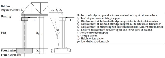
Figure 5.
Displacement components of bridge support according to [23].
3. Numerical Models for TBI Analysis Due to Thermal Actions
To calculate additional temperature stresses in CWRs, longitudinal displacements of the track and bridge, the size of rail gap due to rail cracking, as well as the relevant compressive force for checking the track stability, numerical models for TBI analysis due to thermal actions have been developed using the finite element-based software Midas Civil 2022 (v1.2) [39]. The numerical models include (Figure 6) [40]:
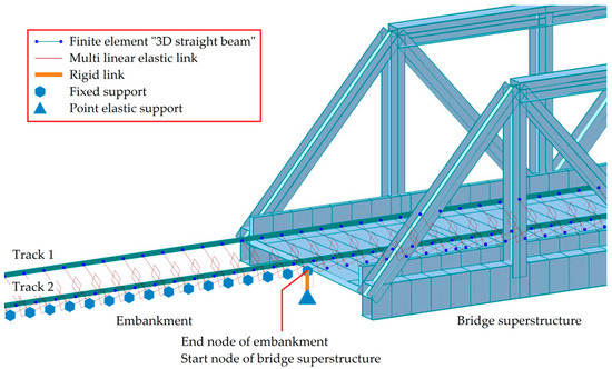
Figure 6.
Elements of numerical models for TBI analysis due to thermal actions.
- “3D straight beam” finite elements [41] used for modeling the track and bridge structure;
- “General elastic links” used for modeling bridge supports and embankments;
- “Rigid links” used for modeling connections between the bridge superstructure and bridge supports;
- “Multi linear elastic links” used for modeling connections between the track and bridge structure.
A parametric study was carried out to calculate additional temperature stresses of two steel railway bridges with CWRs and the maximum values of expansion lengths according to UIC Code 774-3 [23]: simply supported truss bridge with the expansion length of 60 m and continuous truss bridge with the expansion lengths of 2 × 60 m (Figure 7). Bridge structures were designed to satisfy the deformation criteria for the application of CWRs on the bridge, according to [23,25]. Moreover, CWRs on the bridge were designed to satisfy the maximum permissible additional compressive stresses of σa,c ≤ 72 N/mm2, as well as the maximum permissible additional tensile stresses of σa,t ≤ 92 N/mm2, according to technical regulations [23,25,42].
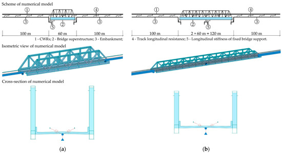
Figure 7.
Numerical models for TBI analysis due to thermal actions: (a) Simply supported truss bridge with expansion length of 60 m and (b) Continuous truss bridge with expansion lengths of 2 × 60 m.
The main track and bridge parameters used in the numerical models of the investigated steel truss bridges with CWRs are:
- Rail profile 60E1;
- Track longitudinal resistance of 20 kN/m for the relative displacement of 2 mm on the entire track length in summer conditions;
- Track longitudinal resistance of 30 kN/m for the relative displacement of 0.5 mm on the entire track length in winter conditions;
- Bridge expansion length of 60 m for the simply supported truss bridge, i.e., 2 × 60 m for the continuous truss bridge;
- Longitudinal stiffness of fixed bridge support of 300,000 kN/m for the simply supported truss bridge, i.e., 600,000 kN/m for the continuous truss bridge.
Numerical simulations were carried out assuming temperature changes in the bridge superstructure equal to +35 °C in summer conditions, i.e., −35 °C in winter conditions, according to [25].
Table 2 shows the properties of the numerical models for the TBI analysis due to thermal actions such as type and number of finite and link elements, as well as the track and bridge parameters, including the corresponding geometric and material properties of the CWRs and the bridge.
Table 2.
Properties of the numerical models for TBI analysis due to thermal actions.
Prior to the parametric study, the verification and evaluation of the accuracy of the numerical results was carried out. According to the recommendations of UIC Code 774-3 [23], the verification was carried out on the test case E1-3 shown in Appendix-D of this document. Table 3 shows the properties of the test case E1-3. Verification of the additional temperature stresses calculated numerically was carried out for summer conditions and temperature change in the bridge superstructure equal to +35 °C.
Table 3.
Properties of the test case E1-3 for verification of the numerical results in Midas Civil software according to UIC Code 774-3 [23,43].
In addition, verification of the total temperature stresses obtained from the numerical analysis was carried out for temperature change in the bridge superstructure equal to +35 °C and temperature change in CWRs equal to +50 °C according to [23]. Table 4 shows the maximum values of the additional and total temperature stresses, as well as the percentage error of the numerical results compared to the results obtained using the UIC Code 774-3.
Table 4.
The maximum values of additional and total temperature stress in test case E1-3 in summer conditions [23,43].
The discrepancy of +3.91% between the numerical results and UIC Code results is significantly smaller than the maximum permissible error of 10%, according to [23], which confirms the satisfactory accuracy of the conducted numerical analysis. Moreover, additional temperature stresses calculated using numerical analysis are higher than the UIC Code results, which is on the safety side for the control calculations of additional stresses in CWRs on the bridge. On the other hand, the difference between the numerical and UIC Code results in terms of total temperature stresses is −2.59%, which is also satisfactory according to [23], but it is not on the safety side from the aspect of track stability control.
4. Results and Discussion
Based on the developed numerical models, a comprehensive parametric study was carried out to quantify the effects of both track and bridge parameters on additional temperature stresses in CWRs. Accordingly, in terms of track parameters, three cases of the rail profile, as well as five cases in summer conditions, and six cases in winter conditions of the track longitudinal resistance were analyzed. Regarding the bridge parameters, three cases of the bridge expansion length, as well as five cases of the longitudinal stiffness of fixed bridge support, were considered in the parametric study as well.
4.1. Effect of Rail Cross-Sectional Area Parameter
Figure 8 shows the diagrams of additional temperature stresses in summer and winter conditions depending on the rail profile.
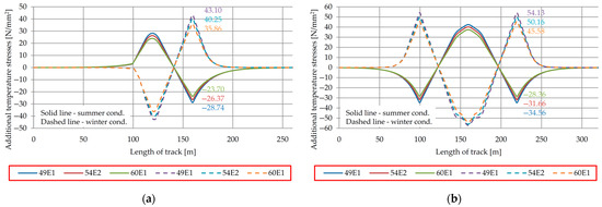
Figure 8.
Effect of rail cross-sectional area parameter on additional temperature stresses in CWRs on (a) Simply supported truss bridge with expansion length of 60 m and (b) Continuous truss bridge with expansion lengths of 2 × 60 m.
Table 5 shows the maximum values of additional temperature stresses depending on the rail profile, along with the percentage reduction of the additional temperature stresses as the rail cross-sectional area increases.
Table 5.
The maximum values of additional temperature stresses depending on the rail cross-sectional area parameter.
As expected, additional temperature stresses can be reduced by increasing the rail cross-sectional area, which can be considered an efficient measure for the reduction of the additional temperature stresses of CWRs. However, it should be noted that the choice of rail profile depends on the category of the railway line, the traffic load, and the maintenance plan.
4.2. Effect of Track Longitudinal Resistance Parameter
Figure 9 and Figure 10 show the typical and reduced track longitudinal resistances on bridges in summer and winter conditions. The typical track longitudinal resistance on the bridge in summer conditions is 20 kN/m for a relative displacement of 2 mm (the track is slipping through the ballast). On the other hand, the typical track longitudinal resistance on the bridge in winter conditions varies from 23.33 kN/m to 30 kN/m for the relative displacement of 0.5 mm (the rails are slipping through the rail fastening systems, which corresponds to the minimum required longitudinal resistance of the rail ranging from 7 kN to 9 kN according to [44]).
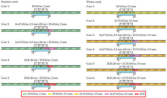
Figure 9.
Cases of track longitudinal resistance in summer and winter conditions for simply supported truss bridge with expansion length of 60 m.
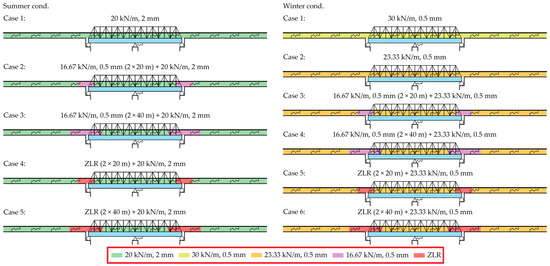
Figure 10.
Cases of track longitudinal resistance in summer and winter conditions for continuous truss bridge with expansion lengths of 2 × 60 m.
Figure 11 shows the diagrams of additional temperature stresses in summer and winter conditions depending on the track’s longitudinal resistance.
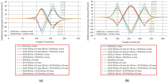
Figure 11.
Effect of track longitudinal resistance parameter on additional temperature stresses in CWRs on (a) Simply supported truss bridge with expansion length of 60 m and (b) Continuous truss bridge with expansion lengths of 2 × 60 m.
Table 6 shows the maximum values of additional temperature stresses depending on the track longitudinal resistance, along with the percentage reduction of the additional temperature stresses as the track longitudinal resistance decreases.
Table 6.
The maximum values of additional temperature stresses depending on the track longitudinal resistance parameter.
Based on the obtained results, additional temperature stresses can be reduced by decreasing the track longitudinal resistance. Rail fastening systems with reduced longitudinal resistance of the rail (less than 7 kN according to [44]) are applied on a limited length of CWRs on the bridge. The limiting factor for the application of rail fastening systems with reduced longitudinal resistance of the rail is the size of the rail gap due to rail cracking in winter conditions (Figure 12).
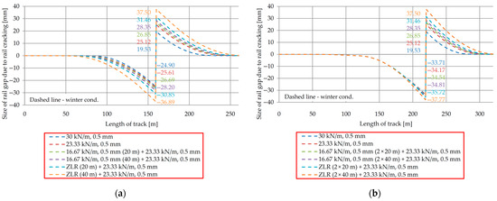
Figure 12.
Effect of track longitudinal resistance parameter on sizes of rail gap due to rail cracking on (a) Simply supported truss bridge with expansion length of 60 m and (b) Continuous truss bridge with expansion lengths of 2 × 60 m.
Maximum rail gap due to rail cracking depending on the track longitudinal resistance, along with the percentage increase of the rail gap as the track longitudinal resistance decreases, are presented in Table 7. Rail gaps were determined for the maximum negative temperature changes of −52.5 °C and −35 °C in the CWRs and bridge superstructure, respectively. In addition, by applying the rail fastening systems with reduced longitudinal resistance of the rail, the longitudinal compressive forces in CWRs relevant for the track stability control in summer conditions are reduced. Table 8 shows the maximum values of the longitudinal compressive forces in CWRs depending on the track longitudinal resistances, as well as the percentage reductions of the longitudinal compressive forces as the track longitudinal resistances decrease. The longitudinal compressive forces were calculated for the maximum positive temperature changes of +42.5 °C and +35 °C in the CWRs and bridge superstructure, respectively.
Table 7.
The maximum sizes of rail gaps due to rail cracking depending on the track’s longitudinal resistance.
Table 8.
The maximum values of longitudinal compressive forces in CWRs depending on the track longitudinal resistance.
4.3. Effect of Bridge Expansion Length Parameter
Variation of the additional temperature stresses in summer and winter conditions depending on the bridge expansion length are depicted in Figure 13.
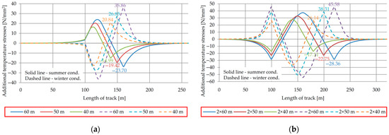
Figure 13.
Effect of bridge expansion length parameter on additional temperature stresses in CWRs on (a) Simply supported truss bridge with expansion length of 60 m and (b) Continuous truss bridge with expansion lengths of 2 × 60 m.
Table 9 shows the maximum values of additional temperature stresses depending on the bridge expansion length, along with the percentage reduction of the additional temperature stresses as the bridge expansion length decreases.
Table 9.
The maximum values of additional temperature stresses depending on the bridge expansion length parameter.
Based on the obtained results, additional temperature stresses can be reduced by decreasing the bridge expansion length. This can be achieved by changing the position of the roller and fixed bridge supports or by decreasing the bridge length and increasing the length of the embankment during the design stage.
4.4. Effect of Longitudinal Stiffness of Fixed Bridge Support Parameter
Figure 14 shows the diagrams of additional temperature stresses in summer and winter conditions depending on the longitudinal stiffness of the fixed bridge support.
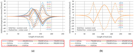
Figure 14.
Effect of longitudinal stiffness of fixed bridge support parameter on additional temperature stresses in CWRs on (a) Simply supported truss bridge with expansion length of 60 m and (b) Continuous truss bridge with expansion lengths of 2 × 60 m.
Table 10 shows the maximum values of additional temperature stresses depending on the longitudinal stiffness of the fixed bridge support, along with the percentage reduction/increase of additional temperature stresses as the longitudinal stiffness of the fixed bridge support decreases/increases.
Table 10.
The maximum values of additional temperature stresses depending on the longitudinal stiffness of fixed bridge support.
Based on the obtained results, additional temperature stresses can be reduced by decreasing the longitudinal stiffness of the fixed bridge support. This reduction can be achieved by using more flexible bridge substructures in the longitudinal direction (foundations, piers, and bearings). For the symmetric continuous steel truss bridge with fixed support in the middle of the structure, the variation in the longitudinal stiffness of the fixed support did not affect the variation in additional temperature stresses (Figure 14b). In practice, the reduction of additional temperature stresses resulting from a decrease in the longitudinal stiffness of a fixed bridge support is notably smaller than the theoretical predictions. This is attributed to the limitation in the longitudinal displacement of the bridge structure caused by the acceleration or braking of railway vehicles, according to [23,25].
4.5. Total Additional Stresses and Longitudinal Displacements of Track and Bridge
Figure 15 shows the diagrams of total additional stresses in summer and winter conditions depending on the track’s longitudinal resistance. The effects of temperature change in the bridge superstructure, acceleration/braking of the railway vehicle, and vertical load of the railway vehicle were considered.
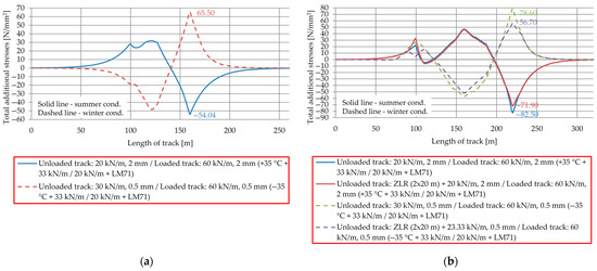
Figure 15.
Effect of track longitudinal resistance parameter on total additional stresses in CWRs on (a) Simply supported truss bridge with expansion length of 60 m and (b) Continuous truss bridge with expansion lengths of 2 × 60 m.
Calculations were performed for temperature changes in the bridge superstructure of +35 °C in summer conditions, i.e., −35 °C in winter conditions. The load induced by the acceleration of the railway vehicle is 33 kN/m (total force ≤ 1000 kN), while the load induced by braking of the railway vehicle is 20 kN/m (total force ≤ 6000 kN). The vertical load of the railway vehicle is adopted according to LM71 [25].
Table 11 shows the maximum values of total additional stresses depending on the track longitudinal resistance, as well as their comparison with the permissible additional compressive and tensile stresses.
Table 11.
The maximum values of total additional stresses depending on the track longitudinal resistance parameter.
In the case of the simply supported truss bridge with an expansion length of 60 m, both the maximum total additional compressive and tensile stresses did not exceed the permissible additional compressive and tensile stresses in CWRs, according to [23,25]. Consequently, no further reduction of the additional temperature stresses in CWRs was required.
On the other hand, in the case of continuous truss bridges with expansion lengths of 2 × 60 m, the maximum total additional compressive stresses in summer conditions exceeded the permissible additional compressive stresses in CWRs. Consequently, a reduction of additional temperature stresses in CWRs was required. This reduction was achieved by applying the ZLR reduced resistances of the unloaded track (see Table 11).
Figure 16 shows the diagrams of the longitudinal displacements of the track and bridge structures in summer and winter conditions, including the vertical load and acceleration/braking of the railway vehicle.
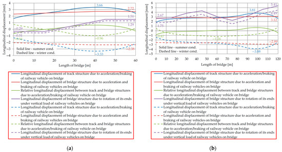
Figure 16.
Longitudinal displacements of track and bridge structures for (a) Simply supported truss bridge with expansion length of 60 m and (b) Continuous truss bridge with expansion lengths of 2 × 60 m.
The corresponding maximum values of the longitudinal displacements, as well as the permissible longitudinal displacements of the track and bridge structures according to [23,25], are given in Table 12.
Table 12.
The maximum values of longitudinal displacements of track and bridge structures.
Based on the obtained results, the longitudinal displacements for both investigated bridge structures are less than the corresponding permissible longitudinal displacements.
5. Conclusions
In this paper, numerical analysis based on the finite element method was used to determine additional temperature stresses in CWRs on steel truss railway bridges. Two types of steel bridges with CWRs and maximum expansion lengths according to UIC Code 774-3 [23] were analyzed: (1) simply supported truss bridge with expansion length of 60 m and (2) continuous truss bridge with expansion lengths of 2 × 60 m. The key contribution of this study is reflected in the quantification of the effects of track and bridge parameters on the reduction of additional temperature stresses in CWRs on steel truss railway bridges through an extensive parametric study. In the conducted parametric study, it was confirmed that by increasing the rail cross-sectional area, decreasing the track longitudinal resistance, decreasing the bridge expansion length, and decreasing the longitudinal stiffness of fixed bridge support all contribute to reducing the additional temperature stresses in CWRs on steel truss railway bridges.
Based on the obtained results of the study, the following conclusions were drawn:
- The track longitudinal resistance has the most significant impact on the reduction of the additional temperature stresses. Its influence ranges from 4% to 72%, depending on factors such as the type of steel truss railway bridge, the type of rail fastening system, and the limited size of the rail gap due to rail cracking in winter conditions. Reducing the track longitudinal resistance results in increasing the size of the rail gap due to rail cracking by 11% to 67%. Moreover, due to this reduction, the longitudinal compressive force in CWRs relevant for the track stability control in summer conditions is decreased as well from 1% to 14%;
- Reducing the bridge expansion length by 10 m results in a reduction of additional temperature stresses from 16% to 25%, depending on the type of steel truss railway bridge;
- The cross-sectional area of the rail also contributes to the reduction of additional temperature stresses. This reduction varies from 7% to 18%, depending on the type of steel truss railway bridge and the type of rail profile;
- The longitudinal stiffness of the fixed bridge support has a minor impact on the reduction of additional temperature stresses. While theoretically, its influence could reach up to 50% depending on the type of steel truss railway bridge and the value of the longitudinal stiffness of the fixed bridge support, in practical engineering scenarios, its effect is notably diminished due to the limited longitudinal displacement of the bridge structure caused by the acceleration/braking of a railway vehicle on the bridge.
Future research will be directed toward the experimental evaluation of the effects of TBI due to thermal actions, taking into account the uneven temperature distribution in the bridge structure.
Author Contributions
Conceptualization, N.M., M.N.-D., M.A. and S.L.; methodology, N.M.; formal analysis, N.M., M.N.-D., M.A., S.L., U.M. and Z.Z.; resources, N.M. and U.M.; writing—original draft preparation, N.M.; writing—review and editing, N.M., M.N.-D., M.A., S.L., U.M. and Z.Z.; visualization, N.M.; supervision, M.N.-D., M.A. and S.L. All authors have read and agreed to the published version of the manuscript.
Funding
This research was funded by the Ministry of Science, Technological Development and Innovation of the Republic of Serbia, grant number 200092.
Data Availability Statement
Not applicable. All relevant data are included in the manuscript.
Acknowledgments
The results presented in this article are part of research from Nikola Mirković’s doctoral dissertation, which is in the process of review and evaluation. The authors would like to thank the company Mostprojekt a.d. Belgrade for technical support.
Conflicts of Interest
The authors declare no conflict of interest. The funders had no role in the design of the study, in the collection, analyses, or interpretation of data, in the writing of the manuscript, or in the decision to publish the results.
References
- Xiao, F.; Sun, H.; Mao, Y.; Chen, G.S. Damage identification of large-scale space truss structures based on stiffness separation method. Structures 2023, 53, 109–118. [Google Scholar] [CrossRef]
- Nasr, A.; Kjellström, E.; Björnsson, I.; Honfi, D.; Ivanov, O.L.; Johansson, J. Bridges in a changing climate: A study of the potential impacts of climate change on bridges and their possible adaptations. Struct. Infrastruct. Eng. 2020, 16, 738–749. [Google Scholar] [CrossRef]
- Palin, E.J.; Stipanovic Oslakovic, I.; Gavin, K.; Quinn, A. Implications of climate change for railway infrastructure. Wiley Interdiscip. Rev. Clim. Chang. 2021, 12, e728. [Google Scholar] [CrossRef]
- CERD (Conference of European Directors of Roads). Adaptation to Climate Change; CERD: Brussels, Belgium, 2012. [Google Scholar]
- Delgado, D.; Aktas, C.B. Resilience of rail infrastructure in the US Northeast corridor. Procedia Eng. 2016, 145, 356–363. [Google Scholar] [CrossRef][Green Version]
- Meyer, M.D.; Weigel, B. Climate change and transportation engineering: Preparing for a sustainable future. J. Transp. Eng. 2011, 137, 393–403. [Google Scholar] [CrossRef]
- NRC (National Research Council). Potential Impacts of Climate Change on U.S. Transportation (Special Report 290); NRC: Washington, DC, USA, 2008. [Google Scholar]
- CCSP (Climate Change Science Program). Impacts of Climate Change and Variability on Transportation Systems and Infrastructure: Gulf Coast Study, Phase I. A Report by the U.S. Climate Change Science Program and the Subcommittee on Global Change Research; CCSP: Washington, DC, USA, 2008. [Google Scholar]
- Fryba, L. Thermal interaction of long welded rails with railway bridges. Rail Int. 1985, 16, 5–24. [Google Scholar]
- Ruge, P.; Birk, C. Longitudinal forces in continuously welded rails on bridgedecks due to nonlinear track-bridge interaction. Comput. Struct. 2007, 85, 458–475. [Google Scholar] [CrossRef]
- Ruge, P.; Widarda, D.R.; Schmälzlin, G.; Bagayoko, L. Longitudinal track-bridge interaction due to sudden change of coupling interface. Comput. Struct. 2009, 87, 47–58. [Google Scholar] [CrossRef]
- Luo, J.; Zeng, Z. A novel algorithm for longitudinal track-bridge interactions considering loading history and using a verified mechanical model of fasteners. Eng. Struct. 2019, 183, 52–68. [Google Scholar] [CrossRef]
- Zhang, J.L.; Wu, D.J.; Li, Q. Loading-history-based track-bridge interaction analysis with experimental fastener resistance. Eng. Struct. 2015, 83, 62–73. [Google Scholar] [CrossRef]
- Ryjáček, P.; Vokáč, M. Long-term monitoring of steel railway bridge interaction with continuous welded rail. J. Constr. Steel Res. 2014, 99, 176–186. [Google Scholar] [CrossRef]
- Mirza, O.; Kaewunruen, S.; Dinh, C.; Pervanic, E. Numerical investigation into thermal load responses of railway transom bridge. Eng. Fail. Anal. 2016, 60, 280–295. [Google Scholar] [CrossRef]
- Mubarack, C.A.; Upadhyay, A. Stability of continuous welded rail on steel bridge subjected to thermal loading. Structures 2021, 34, 4524–4531. [Google Scholar] [CrossRef]
- Kumar, R.; Upadhyay, A. Effect of temperature gradient on track-bridge interaction. Interact. Multiscale Mech. 2012, 5, 1–12. [Google Scholar] [CrossRef]
- Yun, K.M.; Park, B.H.; Bae, H.U.; Lim, N.H. Suggestion for allowable additional compressive stress based on track conditions. Proc. Inst. Mech. Eng. Part F J. Rail Rapid Transit 2018, 232, 1309–1325. [Google Scholar] [CrossRef]
- Strauss, A.; Šomodíková, M.; Lehký, D.; Novák, D.; Bergmeister, K. Nonlinear finite element analysis of continuous welded rail-bridge interaction: Monitoring-based calibration. J. Civ. Eng. Manag. 2018, 24, 344–354. [Google Scholar] [CrossRef]
- Diachenko, L.; Benin, A.; Diachenko, A. Track-Bridge interaction problems in high speed bridge design. Int. J. Eng. Technol. 2018, 7, 194–199. [Google Scholar] [CrossRef]
- Salcher, P.; Pradlwarter, H.; Adam, C. Reliability assessment of railway bridges subjected to high-speed trains considering the effects of seasonal temperature changes. Eng. Struct. 2016, 126, 712–724. [Google Scholar] [CrossRef]
- Mirković, N.; Popović, Z.; Pustovgar, A.P.; Lazarević, L.; Zhuravlev, A.V. Management of stresses in the rails on railway bridges. FME Trans. 2018, 46, 636–643. [Google Scholar] [CrossRef]
- UIC (International Union of Railways). UIC Code 774-3. Track/bridge Interaction. Recommendations for Calculations, 2nd ed.; UIC: Paris, France, 2001. [Google Scholar]
- UIC (International Union of Railways). UIC Code 776-2. Design Requirements for Rail-Bridges Based on Interaction Phenomena between Train, Track and Bridge, 2nd ed.; UIC: Paris, France, 2009. [Google Scholar]
- EN 1991-2:2003/AC:2010; Eurocode 1: Actions on Structures—Part 2: Traffic Loads on Bridges. CEN (European Committee for Standardization)/Technical Committee 250; CEN: Brussels, Belgium, 2010.
- Krontal, L. Zum Entwurf von Eisenbahnbrücken. Struct. Proj. Eisenbahnbrücken 2014, 1. Available online: https://application.wiley-vch.de/books/sample/3433030979_c01.pdf (accessed on 10 July 2023).
- Freystein, H. Interaktion Gleis/Brücke–Stand der Technik und Beispiele. Stahlbau 2010, 79, 220–231. [Google Scholar] [CrossRef]
- EN 1991-1-5:2003/AC:2009; Eurocode 1: Actions on Structures—Part 1–5: General Actions—Thermal Actions. CEN (European Committee for Standardization)/Technical Committee 250; CEN: Brussels, Belgium, 2009.
- SRPS EN 1991-1-5/NA:2017; Eurocode 1: Actions on structures—Part 1–5: General Actions—Thermal actions—National Annex. ISS (Institute for Standardization of Serbia): Belgrade, Serbia, 2017.
- Hossain, T.; Segura, S.; Okeil, A.M. Structural effects of temperature gradient on a continuous prestressed concrete girder bridge: Analysis and field measurements. Struct. Infrastruct. Eng. 2020, 16, 1539–1550. [Google Scholar] [CrossRef]
- Zhu, Q.X.; Wang, H.; Xu, Z.D.; Spencer, B.F.; Mao, J.X.; Gong, Z.H. Mapping temperature contours for a long-span steel truss arch bridge based on field monitoring data. J. Civ. Struct. Health Monit. 2021, 11, 725–743. [Google Scholar] [CrossRef]
- Zhu, Q.; Wang, H.; Spencer, B.F., Jr. Investigation on the mapping for temperature-induced responses of a long-span steel truss arch bridge. Struct. Infrastruct. Eng. 2022, 1–18. [Google Scholar] [CrossRef]
- Xiao, F.; Hulsey, J.L.; Balasubramanian, R. Fiber optic health monitoring and temperature behavior of bridge in cold region. Struct. Control. Health Monit. 2017, 24, e2020. [Google Scholar] [CrossRef]
- Yun, K.M.; Bae, H.U.; Moon, J.; Kim, J.J.; Park, J.C.; Lim, N.H. Quantification of ballasted track-bridge interaction behavior due to the temperature variation through field measurements. NDT&E Int. 2019, 103, 84–97. [Google Scholar]
- Mirković, N.; Brajović, L.; Popović, Z.; Todorović, G.; Lazarević, L.; Petrović, M. Determination of temperature stresses in CWR based on measured rail surface temperatures. Constr. Build. Mater. 2021, 284, 122713. [Google Scholar] [CrossRef]
- Mirković, N.; Popović, Z.; Lazarević, L.; Vilotijević, M.; Milosavljević, A. Railway bridges on interoperable lines: Aspect of track/bridge interaction. Građevinski Mater. I Konstr. 2018, 61, 19–34. [Google Scholar] [CrossRef]
- Mirković, N.; Popović, Z.; Lazarević, L.; Vilotijević, M. UIC preporuke za projektovanje železničkih mostova. Izgradnja 2017, 71, 247–254. [Google Scholar]
- EN 13674-1:2011+A1:2017; Railway Applications—Track—Rail—Part 1: Vignole Railway Rails 46 kg/m and above. CEN (European Committee for Standardization)/Technical Committee 256; CEN: Brussels, Belgium, 2017.
- Midas Engineering Software. Available online: https://www.midasoft.com/bridge-library/civil/products/midascivil (accessed on 10 July 2023).
- Midas Bridge. Available online: https://www.midasbridge.com/en/solutions/rail-structure-interaction (accessed on 10 July 2023).
- Oñate, E. Structural Analysis with the Finite Element Method. Linear statics. Volume 2. Beams, Plates and Shells, 1st ed.; CIMNE (International Center for Numerical Methods in Engineering) and Springer: Barcelona, Spain, 2013. [Google Scholar]
- SRPS EN 1991-2/NA:2019; Eurocode 1: Actions on Structures—Part 2: Traffic Loads on Bridges—National Annex. ISS (Institute for Standardization of Serbia): Belgrade, Serbia, 2019.
- Midas Civil, Technical Document. Continuous Welded Railway Bridge Analysis (in Accordance with UIC 774-3). Rail-Structure Interaction in Accordance with UIC 774-3. 2012.
- EN 13481-2:2022; Railway Applications—Track—Performance Requirements for Fastening Systems—Part 2: Fastening Systems for Concrete Sleepers in Ballast. CEN (European Committee for Standardization)/Technical Committee 256; CEN: Brussels, Belgium, 2022.


Disclaimer/Publisher’s Note: The statements, opinions and data contained in all publications are solely those of the individual author(s) and contributor(s) and not of MDPI and/or the editor(s). MDPI and/or the editor(s) disclaim responsibility for any injury to people or property resulting from any ideas, methods, instructions or products referred to in the content. |
© 2023 by the authors. Licensee MDPI, Basel, Switzerland. This article is an open access article distributed under the terms and conditions of the Creative Commons Attribution (CC BY) license (https://creativecommons.org/licenses/by/4.0/).