Article

Experimental Study of the Bending Performance of Cold-Formed Steel Channel Beams Considering the Corner Hardening Effect

1
School of Civil Engineering, Nantong Institute of Technology, Nantong 226002, China
2
School of Urban Construction, Changzhou University, Changzhou 213164, China
3
Testing Center of China National Administration of Coal Geology, Jiangsu Design Institute of Geology for Mineral Resources, Xuzhou 221006, China
4
Danyang Municipal Water Resources Bureau, Zhenjiang 212300, China
5
School of Civil Engineering, Yancheng Institute of Technology, Yancheng 224051, China
*
Author to whom correspondence should be addressed.
Buildings 2023, 13(9), 2149; https://doi.org/10.3390/buildings13092149
Submission received: 10 May 2023 / Revised: 19 July 2023 / Accepted: 22 August 2023 / Published: 24 August 2023

Abstract

:
Cold-formed steel channel beam components are increasingly used in lightweight steel buildings owing to the high strength–weight ratio. However, the influence of cold working processes, in relation to corner regions, and how this impacts the bending behavior of channel beams lacks thorough evaluation. In the present study, a series of coupon and bending tests were conducted and the numerical simulation and analytical derivation were supplemented, aiming to investigate the bending performance of cold-formed steel channel beams considering the reinforcement effect in corner regions. The results show that the engineering stress–strain relationships of the flat and corner coupons conformed to the trilinear models with different characteristic parameters. The yielding and ultimate strengths of the corner specimens was increased by 50% and 7%, respectively, compared to the flat coupons due to the cold-bending technique. The strain distribution of the cold-formed channel beams accord with the plane section while the stresses at the corners were 35% higher than those at the flanges, indicting the different mechanical response of the flat and corner regions. The component-based model for cold-formed steel channel beams was established to exactly describe the influence of the cold-bending action, which was greatly validated by the experimental and numerical data with the errors of typical parameters less than 9%.

1. Introduction

Cold-formed structural steel sections made from cold-bent or cold-rolled steel sheets are increasingly used in steel buildings owing to the significant advantages such as higher strength, lighter weight, easier transport and sustainable construction [1,2,3,4]. According to the practical requirements, several cold-formed sections were machined to various cross-section types, such as C-section, Z-section, Rectangular-section and U sections, etc. With the different mechanical features, these cold-formed components were applied as beam, column and purlin members in steel buildings [5,6,7].
During the cold-working process, the mechanical characteristics of steel materials were changed, and the properties of the cold-formed components were thereby different from that of hot-rolled members. S. Hu et al. investigated the mechanical properties of cold-formed steel tubes with flats, corners, raw steel and full-section short columns, and proposed a series of design equations for a cold-formed steel tube [8,9]. D. Wen and Y. Li et al. evaluated the local buckling behaviors of cold-formed steel sections and found that the current international codes were more conservative [10,11]. X. Fu and L. Ton et al. provided a practical method for calculating the strength of cold-formed reinforcement effects based on the yield strength tests of the cold-formed channel steel effect [12,13]. In addition, B. Young et al. investigated the cold-formed stainless steel tubular structures taking the initial geometric imperfection and residual stress into considerations [14,15,16]. J. Ma et al. conducted the extensive experimental and numerical studies on cold-formed square hollow sections (SHS), rectangular hollow sections (RHS) and circular hollow sections (CHS), and compared the results with the written design methods for cold-formed HSS tubular beams [17]. These design equations and tests have assisted in the development of current specifications.
As the component widely used in steel structures, the bending capacity of cold-formed steel beams was changed due to the cold forming action [18]. Several authors paid attention to their flexural performance. For example, Y. Lee and J. Ye et al. conducted a numerical study of cold-formed channels to optimize them. The results indicated that the bending capacity of the cold-formed beams could be improved by increasing the cross-sectional area and beam depth [3,4]. C. Szymczak et al. investigated the local buckling behavior of thin-walled steel channels under bending and proposed an analytical solution to the local buckling problem of cold-formed beams [6]. H. Wang et al. conducted the pure and non-pure bending tests on the cold-formed steel C-sections, which indicated that the flexural strength under impure bending was higher than that under pure bending, and the increasing magnitude was related to the flexural mode [19]. D. Ayhan and B. Rossi et al. proposed a new material model to predict the reinforcement of cold-formed sections based on existing models [20,21]. B. Schafer and I. Misiūnaitė et al. experimentally studied the effect of local deformation of cold-formed steel on the overall bending performance [22,23]. F. Alireza et al. studied Butterfly shaped beams with hexagonal cut-outs inside of the beam’s web, and predicted the force–displacement relationship of a butterfly shaped beam with satisfactory accuracy [24]. F. Alireza and K. Young et al. applied the novelty dampers as the seismic system of the structure to resist shear loads. The experimental tests and the finite element analysis indicated that the novelty dampers could improve better energy dissipation capacity for the structure compared to the traditional dampers [25,26]. F. Alireza et al. used structural fuses as steel plates subjected to shear loads and established the analytical procedures for predicting fuse behavior [27,28]. It was noted form the above-mentioned studies that the flexural performance of cold-formed channels is not yet fully understood. The effect of cold-forming work on the material property and the global bending behavior of steel channel beams needs to be comprehensively investigated to establish a more reasonable and structural design.
For this purpose, axial tensile tests were conducted on the flat and corner coupons, respectively, aiming at verifying the material properties of the flat and corner regions in cold-formed steel channels. Then, the four-point bending tests and the FE simulation of the channel beams were carried out to reveal the effect of cold forming at corners. Finally, the component-based model was established and validated to reasonably calculate the cold-formed steel channel beams.

2. Experimental Program

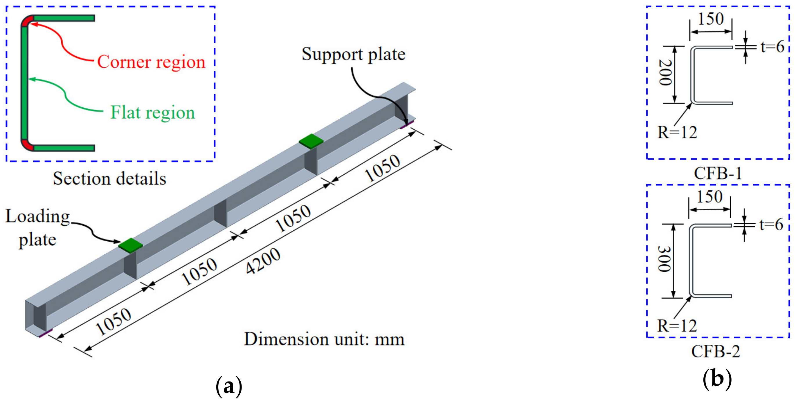
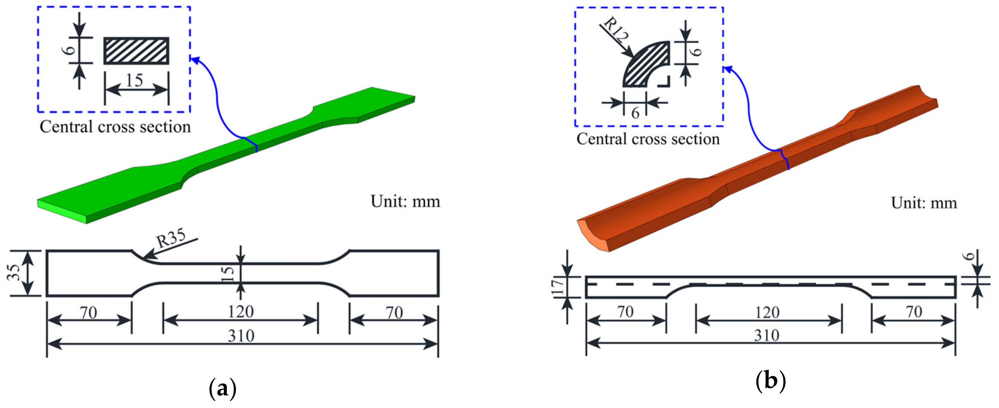
2.1. Details of Cold-Formed Steel Channel Specimens and Coupon Specimens

Two channel beam specimens were designed and manufactured by cold bending forming Q235B steel plates for the four-point bending tests. Figure 1 shows the geometrical and dimension details of the beam specimens. The span of the cold-formed channel beam specimens was all set to be 4200 mm and the transverse stiffeners were installed at an equal space of 1050 mm. To avoid severe stress concentration, the two plates with 10 mm thickness were arranged at the lower flange of the end supporting locations and the other two 10 mm-thick plates were fixed at upper flange of loading positions. As shown in Figure 1b, the width of channel sections was set to be 150 mm, and the heights of the channel sections were designed as 200 mm and 300 mm for specimens CFB-1 and CFB-2, respectively. In addition, the thickness of steel channels was set to 6 mm. Due to the bend-forming operations, the external diameter was 12 mm and the internal diameter was 6 mm at the corner locations in the channel beam specimens. In addition, the transverse stiffeners were installed by welding. Notably, the heated affected zone may be limited to a certain range, and the global bending behavior of cold-formed steel channels with a long span was particularly analyzed in this study. Hence, the effect of welding was disregarded.
The corner regions were observed to be shaped by 90° bending in the manufacturing process of cold-formed channel beam specimens, which resulted in the differences of material properties of corner parts and flat parts. Hence, prior to the bending tests of cold-formed steel channel beams, the axial tensile tests were conducted to obtain their specific mechanical characteristics. The standard dog-bone flat coupons and the corner coupons were designed in accordance with the GB/T 228.1-2010 standard [29]. Figure 2 indicates the geometrical and dimensional descriptions of tensile coupons. In the bending, six repeated flat specimens and six corner specimens were taken from the web, flange and corner of the same batch of cold-formed steel as spacers. The six flat coupons were divided into two groups, labelled as TF-1~TF-3 and BF-1~BF-3, respectively. In addition, the six corner coupons were divided into two groups, labelled as TC-1~TC-3 and BC-1~BC-3, respectively. The nomenclature was defined as follows: “T” and “B” indicated different sampling locations for the two sample sets, respectively. “F” and “C” denoted the flat and corner cutting locations for the coupons, respectively. Moreover, “1~3” meant the three repeated tensile test samples in each group.

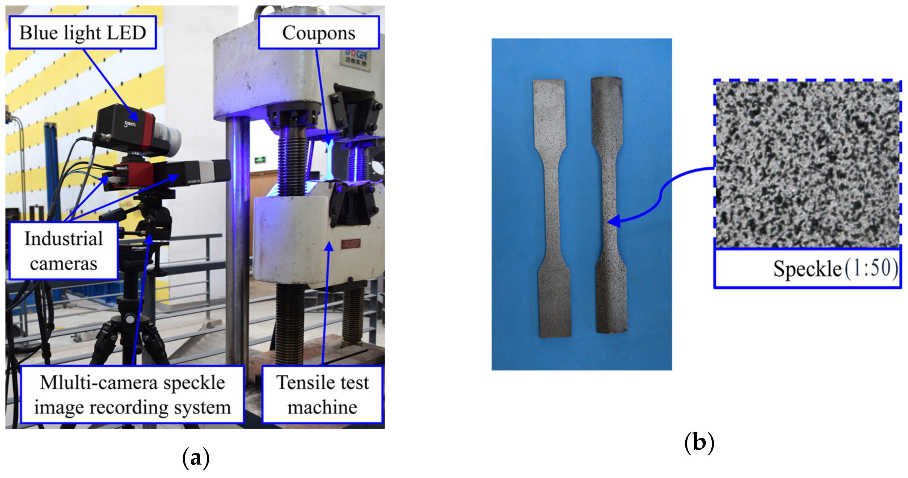
2.2. Tensile Test Set-Up of Corner and Flat Coupons

The set-up of coupon tests was illustrated in Figure 3. The universal test machine with a range of 50 kN was used to complete the coupon tests. A pair of parallel chucks was fixed to clamp the flat specimens and a pair of chucks with a quarter circle ring notch was installed for the corner coupons. The axial tensile loads were applied on the samples at a speed of 1 mm/min according to the GB/T 228.1-2010 standard [29]. The axial loads can be directly outputted from the universal test machine system, thus the nominal axial stress can be obtained knowing the central area value of the coupons. In addition, the extensometer was conventionally arranged to measure the axial tension value of the central segment and then calculate the nominal strain of the coupons. Nevertheless, it should be mentioned that the movement of extensometer and slippage of the clamping chuck would lead to the non-ignorable errors of the experimental data. Thus, the non-contact optical measurement technique based on the digital image correlation (DIC) principle was applied in this study, which could significantly improve the measurement accuracy and simplify the instrument layout. A digital image correlation unit with two industrial cameras and blue light LED was installed to obtain images at 10 Hz. The resolution of the two cameras was 2752 × 2000 pixels with a focal length of 50 mm. As a basis for measurement related to the image, the random speckles were sprayed on the flat and corner of specimens, as illustrated in Figure 3b. Moreover, a calibration board was used to determine the ratio of speckle pixels and the calibration distance before tensile tests. Then, the multi-camera image device and the tensile test machine were triggered synchronously to directly obtain strain field information and uniaxial force throughout the entire loading process. In this way, the stress–strain curves of the flat and corner coupons were captured to describe the material properties of cold-formed channels in detail.

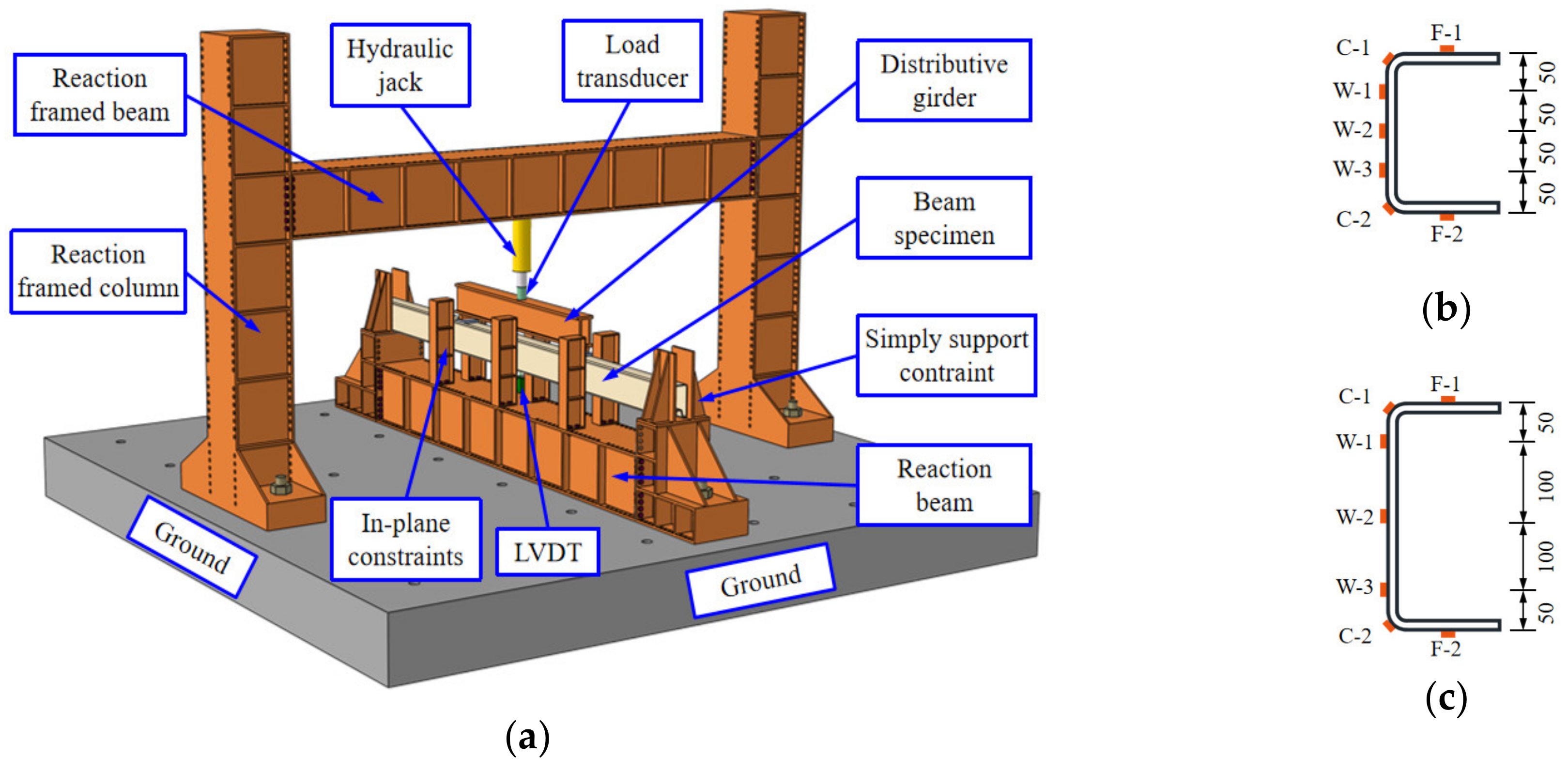
2.3. Bending Test Set-Up for Cold-Formed Steel Channels

The bending tests were further conducted to evaluate the flexural behaviors of cold-formed steel channel beams. Figure 4 shows the equipment set-up for the four-point bending tests. The reaction framed columns and beam were installed to provide the counterforce. Moreover, the ground beam was fixed to the ground by anchors, and a couple of support devices were erected at the ends of beam specimens to provide the in-plane simply supported constraints. Three pairs of in-plane constraints were fixed to avoid the out-plane instability of channel beam specimens subjected to the vertical loads. A hydraulic jack of 1000 kN capacity was arranged for gradual loading with a 10 kN step. Moreover, aimed at monitoring the vertical load values, a load transducer was fixed at the top of the jack. A distributive girder was medially arranged on the top flanges of the steel channel beams, and its end supports were placed on the loading plates. A linear variable displacement transducer (LVDT) with a total stroke of 100 mm was installed at the lower flange in the middle section to record the deflection of the beam specimens. Figure 4b,c indicate the arrangement of strain gauges at the mid-span sections of cold-formed channel beam specimens. The strain gauges F-1 and F-2 were glued to the top and lower flanges of the channel beams, respectively. Three strain gauges named W-1~W-3 were bonded onto the webs at equal intervals. In addition, it should be mentioned that two strain gauges labelled C-1 and C-2 were stuck on the external surface of the upper and lower corner regions to obtain the strain response of the cold-bending part of the steel channel beam specimens.

3. Experimental Results

3.1. Evaluation of Flat and Corner Coupons in Tensile Tests

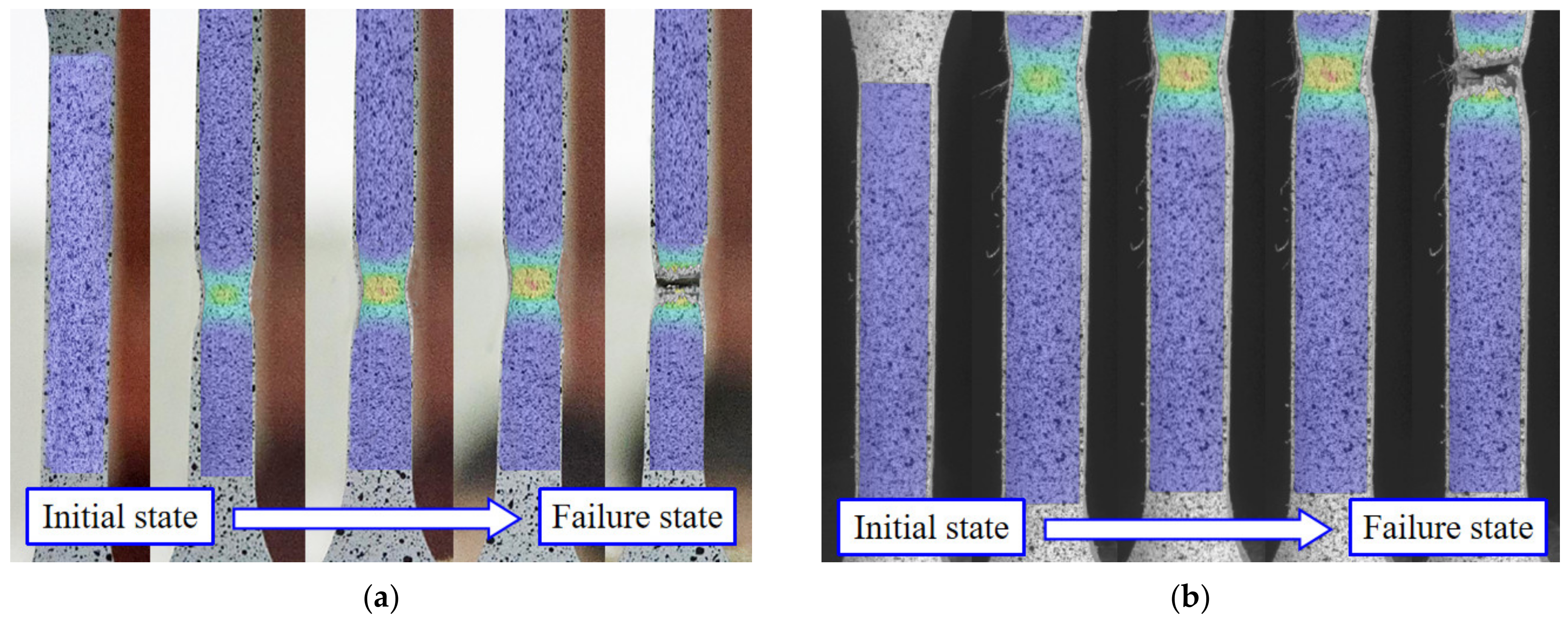
3.1.1. Deformation Process and Failures of Coupons

A series of axial tensile tests were performed on material specimens and the evolution of strain was investigated using the 3D DIC optical measuring instrument. The six flat coupons were TF-1, TF-2, TF-3, BF-1, BF-2 and BF-3, respectively, and the six corner coupons were TC-1, TC-2, TC-3, BC-1, BC-2 and BC-3, respectively. The strain nephograms were obtained by post-processing a series of speckle images, as shown in Figure 5a. It was found that typical necking deformations occurred at the average cross-sectional position of all flat specimens, fracturing at a displacement value of approximately 24 mm. Deformation was also consistently observed at fracture displacement values of approximately 7 mm for all corner specimens. In the cross-section of the flat samples, the necking deformations were occurred in the central area of the samples. However, in the other specimens, the necking deformations were produced at the boundary of parallel segments, as shown in Figure 5b. In the DIC system, the global deformation and strain information of the specimens was obtained. The failure states indicate that the plastic deformation of the corner samples are significantly limited compared to the flat samples due to the cold-bending action.

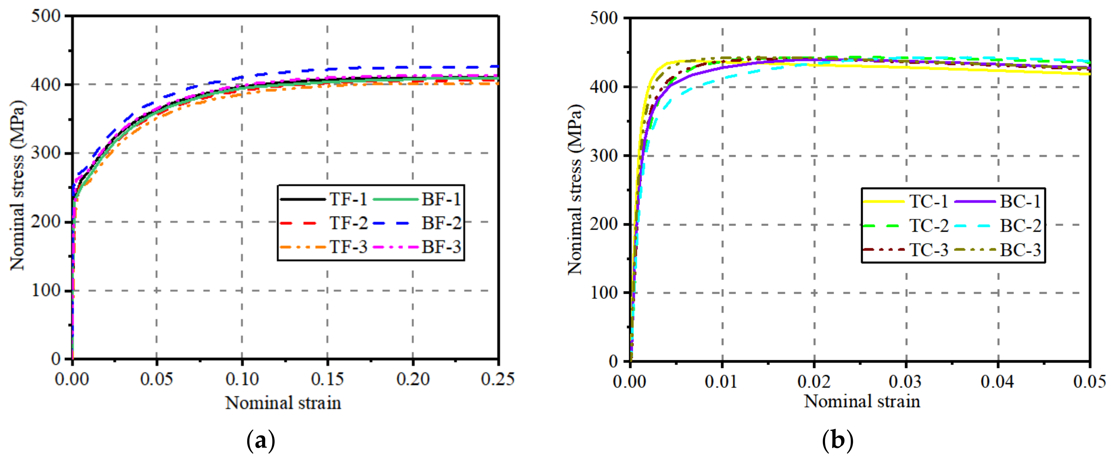
3.1.2. Engineering Stress–Strain Curves of Flat and Corner Coupons

The engineering stress–strain curve was commonly used to describe the constitutive relationship. The stress–strain development was evaluated in present study disregarding the geometrical defects and residual stresses. Moreover, the reduction of the cross-sectional area was ignored under uniaxial load conditions for calculating cross-sectional stress. For flat coupons with rectangular cross-sections, the original thickness (df0) was measured using 3D digital speckle scanning and the original span of the central area of the section (lf0) was obtained using an electronic vernier caliper, so the original cross-sectional area (Afo) was calculated, and the engineering stress (σfe) was obtained from Equation (1). The gauge length (D0) of the observed area of the specimen was set to 120 mm and the axial engineering strain value was directly obtained. Through this method, the engineering stress–strain curve of the flat specimens (TF-1, TF-2, TF-3, BF-1, BF-2 and BF-3) was obtained, as shown in Figure 6a. Similarly to flat coupons, the original thickness (dc0) and the original outer arc length (lc0) of corner coupons with a quarter-circle cross-section were obtained applying the method of 3D digital scanning and the electronic vernier caliper, respectively, as shown in Figure 3a. Thus, the original cross-section area (Ac0) was gained, and the real stress (σce) was defined by Equation (2). This resulted in the determination of engineering stress–strain curves for the corner specimens (TC-1, TC-2, TC-3, BC-1, BC-2 and BC-3), as shown in Figure 6b.
σ fe = F / A f 0
σ ce = F / A c 0
Research has found that the engineering stress–strain curve and load displacement curve have similar characteristics. For the flat specimens, the curves are divided into four phases: elastic phase, yielding phase, strengthening stage and degradation stage. As shown in Figure 6a, this set of curves clearly shows the yield point and ultimate load. The yield plateaus were not obviously displayed in the stress–strain curves due to the wide range of strain. In contrast, the yield point was not visible in the engineering curves for corner samples, as shown in Figure 6b. In this type of stress–strain curve, the yield point is defined as 0.2% of the strain value. The stresses in the cross-sections were developed rapidly to the yield point in the initial stage and then decreased gradually as the uniaxial strains exceeded the peak yield points. Figure 6 shows a comparison of the engineering stress–strain curves for flat and corner specimens. The corner specimens show significantly stronger stress reinforcement in the engineering stress–strain curves compared to the flat specimens with steady strengthening. At a higher tensile stiffness, the stress in the cross-section of the corner specimen reaches its ultimate strength at an early stage of strain development. As shown in Table 1, the mechanical data for flat and angular specimens. The yield point was indicated in the region where the slope of the stress–strain curve drops abruptly, so that the yielding strength (σy) and the yielding strain (εy) were defined as the stress and strain values at the location of the yield point. Similarly, the extreme strength (σu) was determined by the stress value in the peak point and the corresponding strain value was denoted as the extreme strain (εu). Furthermore, the breaking strength (σf) and breaking strain (εf) represent the stress and strain values of the fracture points, respectively. As shown in Table 1, the average engineering yield strength, yield strain, ultimate strength and fracture strength of the corner specimens were 50%, 54%, 7% and 14% higher compared to the planar specimens. Ultimate strain and fracture strain are 93% and 75% lower, respectively. The result demonstrated that the strain-hardening behavior of corner regions was produced owing to the cold-rolling action, while the plastic ductility was highly limited with the ultimate elongation significantly lower than that of the flat samples.

3.2. Evaluation of Cold-Formed Channel Beams in Bending Tests

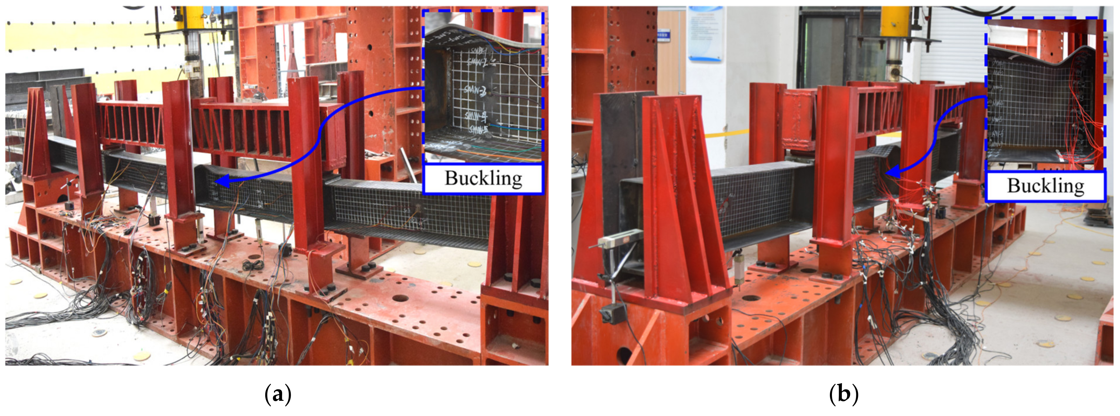
3.2.1. Observations of Steel Channel Beams

The loading processes were carried out in the bending tests and deformations were observed. In the initial stage, the CFB-1 gradually bent with a continuous increase in deflection. When the vertical force reached 150 kN, the local buckling deformation began to occur at the upper flange in the mid-span section. As the load reached 196 kN, the global bending deformation and local buckling deformation in the cold-formed channel beam were considerably serious. Then, the mid-span deflection increased rapidly, and the failure load was 196 kN. Figure 7a shows the deformation state of the CFB-1 at the end of the test. A similar deformation and damage pattern were recorded for specimen CFB-2, as illustrated in Figure 7b. When the force reached 150 kN, the local bending deformation occurred in the upper flange, which became more obvious as the load increased. When the load reached 190 kN, the local deformation was clearly visible, and a loud noise could be heard. Then, the deformation increased rapidly while the load decreased. The ultimate load of specimen CFB-2 was indicated as 196 kN and the state of deformation at the end of the test is shown in Figure 7b.

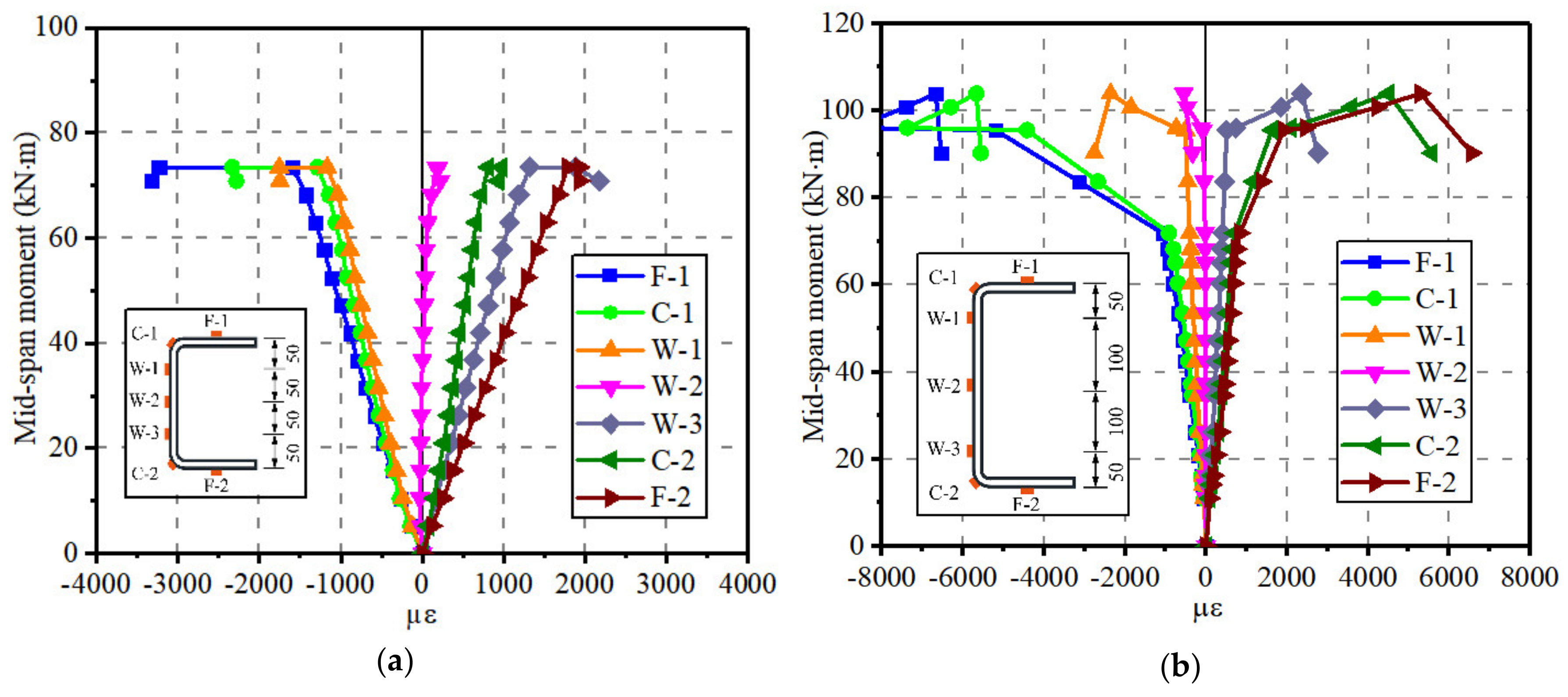
3.2.2. Bending Mechanical Response of Cold-Formed Steel Channel Beams

The 10 kN-stepped vertical loads and corresponding mid-span deflections of cold-formed beam specimens were directly recorded in the bending tests. Then, the mid-span moments and rotations were calculated by the structural mechanical analysis, as shown in Figure 8. It is shown that the moment-rotation curves can be defined as three stages: elastic stage, elastic-plastic stage and plastic stage. At the beginning of bending tests, the external loads linearly increased with the bending deformations. As the test loads reached the yielding capacities, the beam specimens entered the elastic–plastic period. The local buckling deformation occurred and the overall in-plane bending deformations were gradually obvious. Once the loads rose to the ultimate strength, the plastic deformations took place in the cold-formed steel channels. The bending deformations and local buckling in mid-span sections were serious, which caused the failures of channel beam specimens.
The stress–strain developing mechanism of the corner region was observed to change, compared to that of flat region in the steel channel sections owing to the cold bending action. Sectional strains were evaluated by a series of strain gauges. Figure 9 shows the mid-span moment versus the strain curves of cold-formed steel channel beam specimens. As the typical flexural member, the strain values of measure points (F-1, C-1 and W-1) in the compression zone basically correspond to those (F-2, C-2 and W-3) in the tension zone. In addition, the moment-strain curves of corner positions were close to those of the flange locations with a similar distance to the neutral axis. Figure 10 demonstrates the strain distributions of mid-span sections in beam specimens CFB-1 and CFB-2. The sectional strain distributions of cold-formed channel beams conformed to the plane section assumption. The strain developed linearly and distributed anti-symmetrically during the initial loading stage. As the loads increased, the plastic strains were produced in flanges, corners and web edges successively, while the strain distributions were still in accordance with the centrosymmetric regularity. Hence, it can be obtained that the corner parts maintained greater deformation compatibility with the flat parts in the steel channel beams subjected to vertical loads.

4. FE Simulations of Steel Channels with Different Constitutive Models

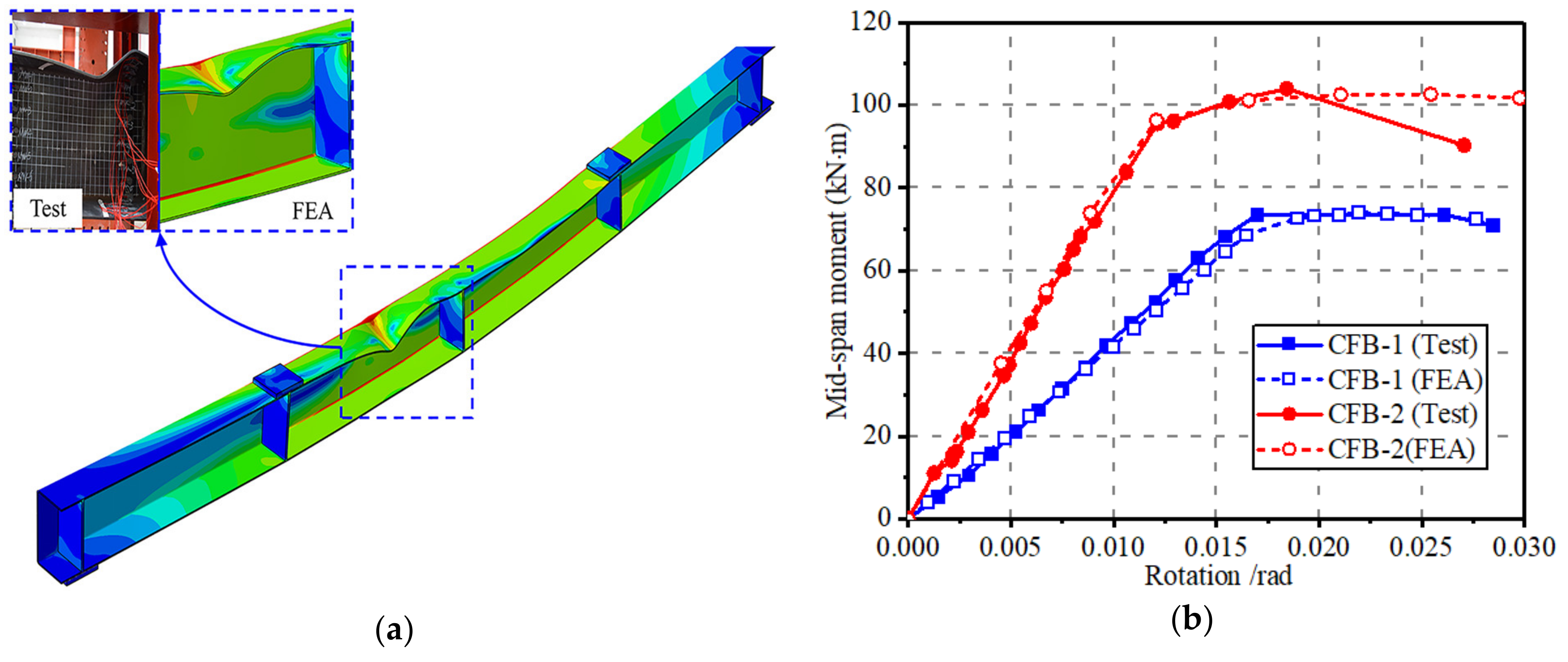
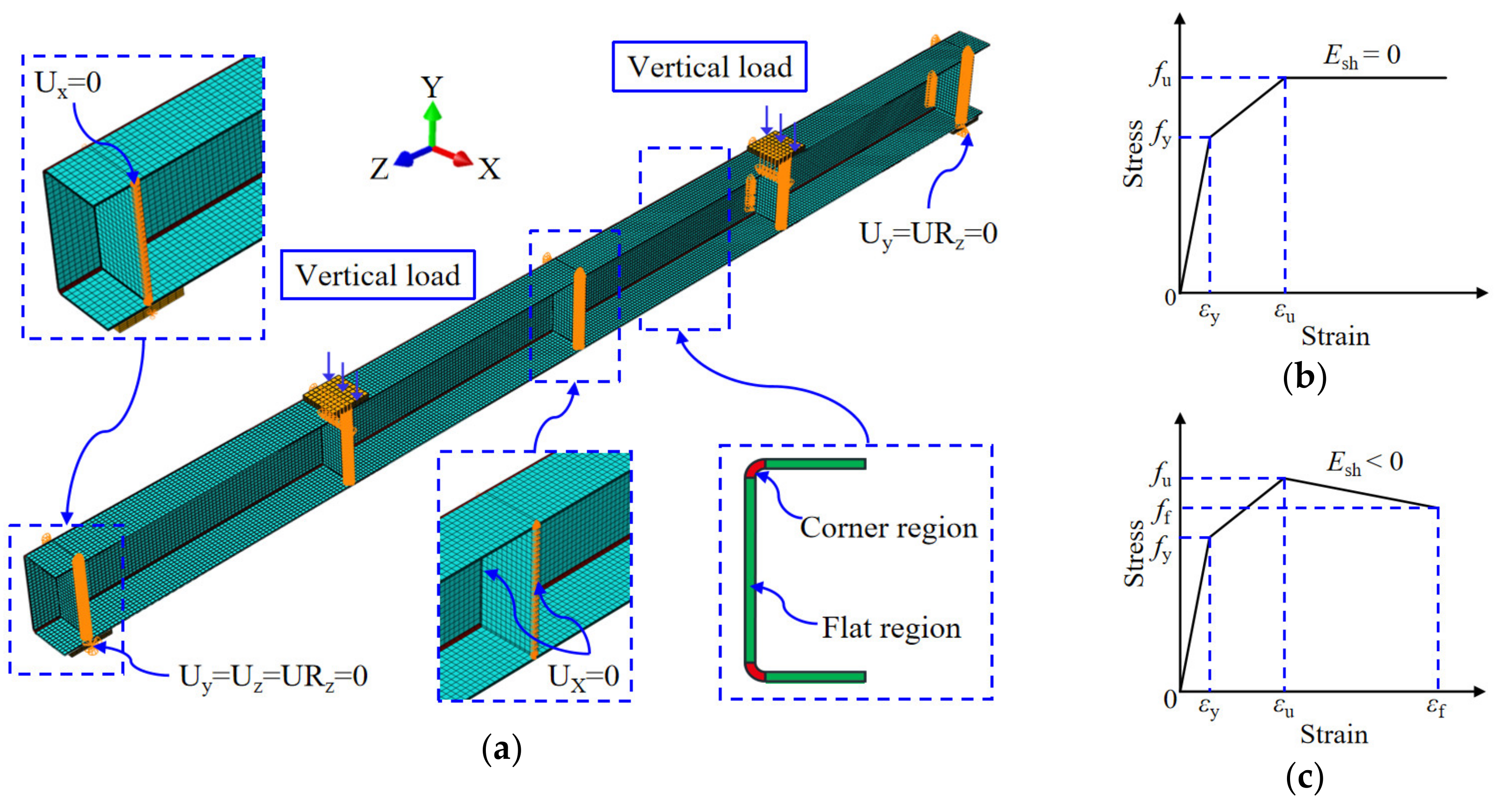
4.1. Establishment and Validation of Steel Channel Beams

The stress response of corner and flat part in cold-formed steel channel beams was further investigated by the calibrated FE simulations in an Abaqus 2016 software environment [30]. Figure 11 shows the 3D FE models of the steel channel with a geometry, mesh, load and boundary condition. The geometry and dimensions were all set to be same as that of beam specimens in experiments. The initial geometric imperfections were introduced in FE simulations of steel components by several authors [6,10,31]. It should be mentioned that this study mainly focused on the effects of cold working on the channel beams, thus the initial imperfections of cold-formed channels were disregarded. The displacements in the Y and Z directions together with the rotation in the Z direction were all initially constrained (Uy, Uz and URz = 0) in the left supporting position. The absolute restraints of displacements in the Y direction and the rotation in the Z direction were set in the right supporting part (Uy and URz = 0) for simulating the boundary conditions in tests. In addition, the restraints Ux = 0 were employed on the stiffeners for imitating the in-plane devices.
It was noted that the force-control mode was adopted in test loading frame. Aimed at improving the computational astringency in the large deformation stage for beam models, the displacement-control mode was used in FE simulations with a consistent loading position. Mesh convergence analysis was performed, which determined the independent mesh size of 5 mm. Moreover, it was noted that cold work obviously affected the mechanical material performance of the corner part in steel channel beams, thus the corner and flat regions were individually defined by the coupon test results, as shown in Figure 11b,c. The “Mises” yielding principle was adopted in the numerical computation of cold-formed steel channels. In addition, the “Nlgeom” algorithm was employed in FEA to consider the effect of nonlinear large deformation.
A comparison of experimental and numerical results was conducted, as presented in Figure 8. The failure modes were highly consistent, as shown in Figure 8a. The global bending behavior and local buckling deformation of cold-formed channel models was greatly simulated. It is shown in Figure 8b that the mid-span bending moment-rotation curves obtained from the tests fit very well with that from the FE predictions in the full ranges. Specifically, the errors of simulated and tested yielding strengths for specimens CFB-1 and CFB-2 were 1% and 4%, respectively. A certain difference was observed in the moment-rotation curves for specimen CFB-2. This may be due to the fact that the force-controlled loading method was applied in bending tests leading to the serious local buckling deformation and capacity degradation at the large deformation stage. As for the numerical simulation, displacement-controlled loading was used, which promoted the computation stability. Generally, the calculated and simulated curves were in the great agreement. Significant coincidence highly validated the FE models of cold-formed steel channels, adopting the different material parameters for the corners and flat locations. Hence, the stress response, especially for the corner regions, can be evaluated based on the experimentally verified numerical results.

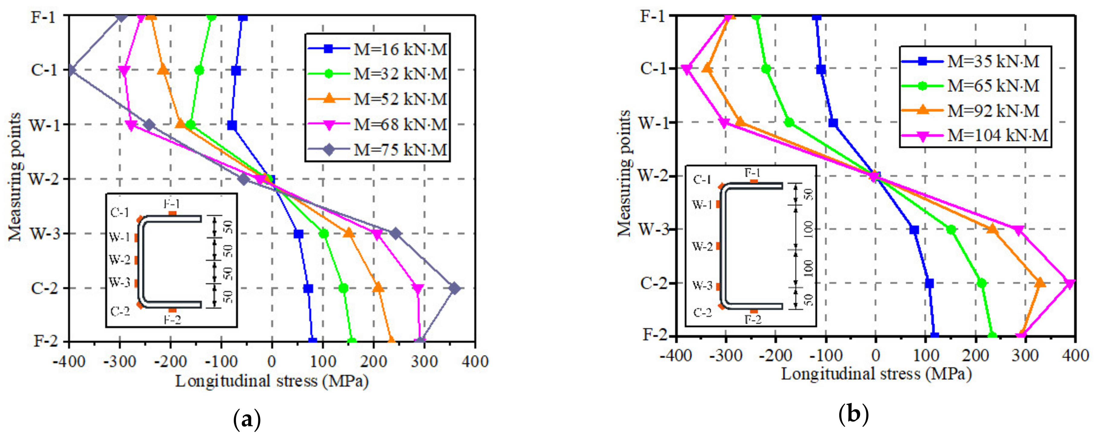
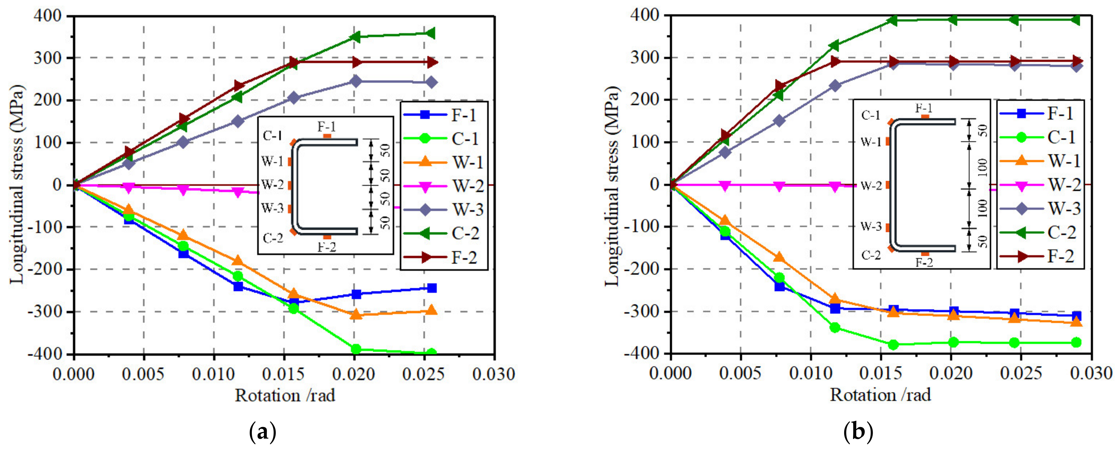
4.2. Stress Development of Cold-Formed Channel Beams

The stress development of mid-span sections of cold-formed channel beams was evaluated by calibrated FE simulations. The longitudinal stress-rotation curves at mid-span sections of the beam specimens are presented in Figure 12. It can be seen that the cross-sectional stress values are basically symmetric around the centroid axes. As the mid-span rotations increase, the stresses of flange, corner and web regions develop in accordance with their constitutive relationships, respectively, obtained by coupon tests. Moreover, it is indicated that the stress values of corner parts (C-1 and C-2) are higher than that of flange parts. The distribution feature is also illustrated in Figure 13. It is mainly because the corner regions were affected by the hardening effect of cold-bending behavior, which led to the greater stress response than flat locations at the same strain states. This means that the section stress states with the identical center distance did not keep consistent for the corner and flange parts. Hence, it is necessary to specifically assess the stress development of every part when calculating the bending properties of cold-formed steel channel beams.

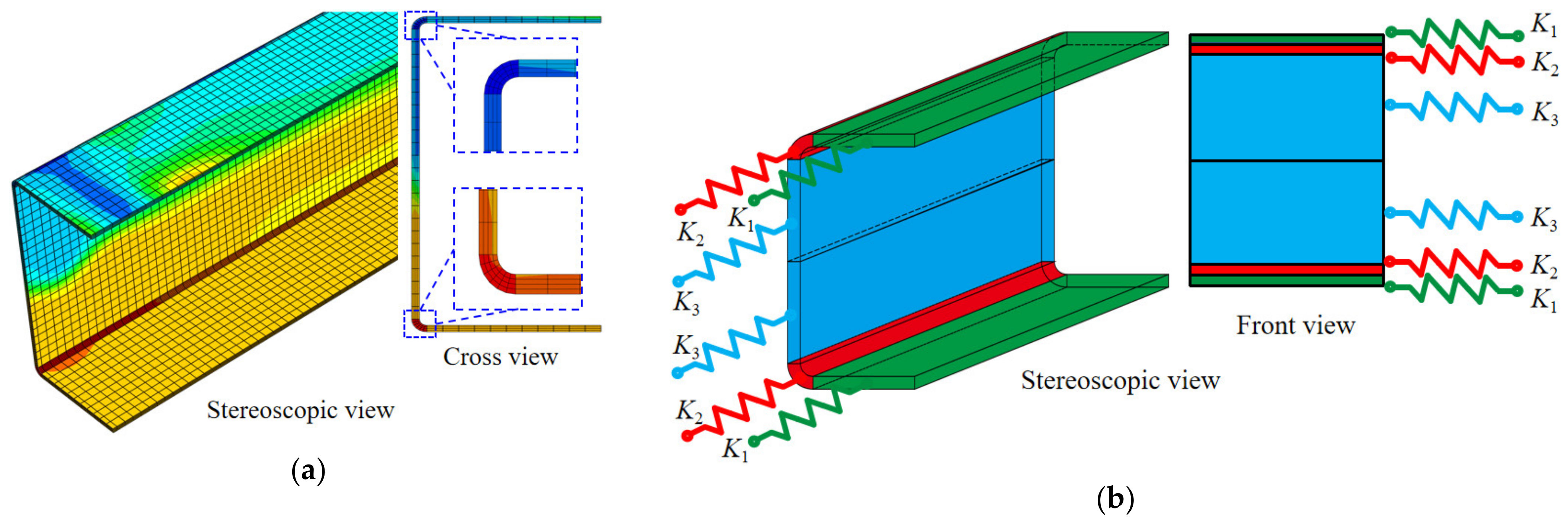
5. Component-Based Model of Cold-Formed Steel Channels

5.1. Development of Component-Based Model

The reasonable moment-rotation model was the basis of structural design for the cold-formed channel beams. The classic models were developed by several authors for cold-formed components, considering the hardening effect by the reinforcement coefficient [32]. However, these existing models could not accurately take the effect of cold-bending deformation into consideration. Hence, the component-based model was developed in this study. According to the experimental and numerical results, the corner parts exhibited greater deformation coordination with the flat parts, as shown in Figure 14a. As a result, the sectional strain values were consistently distributed at the same distance to centroid axes. The stresses in cold-bending corner parts were, however, obviously distinctive compared to the flange areas due to different material–mechanical characteristics. Thus, by describing the mechanical behaviors for the flange, corner and web parts individually, a component-based model of cold-formed steel channel beams was established, as shown in Figure 14b, for accurately estimating the bending property considering the cold-working effect. K1 represents the tensile and compressive behaviors of the upper and lower flanges. K2 denotes the mechanical properties of corner regions in the cold-formed section. K3 simulates the mechanical characteristics of steel webs. It should be mentioned that the plane section assumption was established in this theoretical derivation. K1, K2 and K3 can be determined by the tested constitutive models of corner and flat locations in steel channel beams. Therefore, the relationship between the sectional moment and rotation can be described by Equation (3).
M = (A1K1h1 + A2K2h2 + A3K3h3) × θ
where M denotes the mid-span moment of cold-formed channel beam, θ denotes the mid-span rotation, A1 indicates the area value of flange plate, A2 means the area value of corner part, A3 represents the area of half-web plate, h1 indicates the distance of flange center to the neutral axis, h2 means the distance of corner part center to the neutral axis, and h3 represents the distance between the half-web part center and the neutral axis, respectively.

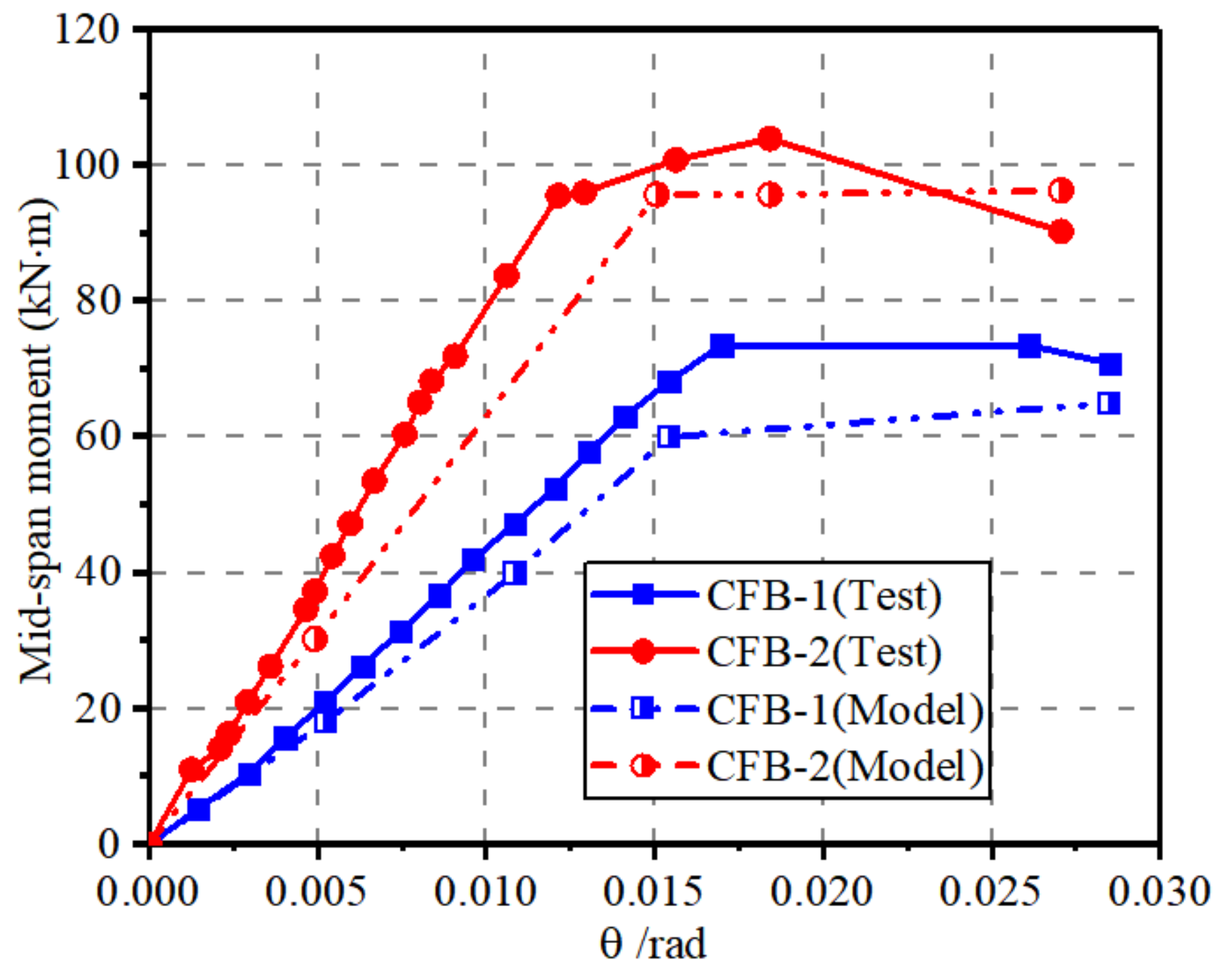
5.2. Validation of Component-Based Model

A comparison of experimental and analytical data was performed, as presented in Figure 15. It can be found that the estimated moment-rotation curves fit well with the tested results, with errors less than 9%, which illustrated the reliability of the component-based model in this study. It should be mentioned that the engineering stress–strain curves of corner and flat coupons were evaluated and used to calculate the bending properties of cold-formed channel beams. As a result, the analytical model slightly underestimated the mid-span moment capacities compared to the experimental curves. It should be mentioned that the mechanical states of the upper and lower web partitions were represented by component K3, respectively. More detailed mechanical components should be developed in further study for more accurate predictions. In general, the component-based model provided the satisfied prediction for the cold-formed steel channel beams considering the corner hardening effect.

6. Conclusions

The present study comprehensively investigated the bending performance of cold-formed steel channel beams. Coupon tests were performed to evaluate the material characteristics of flat and corner locations. In addition, the flexural experiments were conducted and the bending properties of channel beams were examined considering the reinforcing effect of cold-bending corner regions. Moreover, the component-based model was provided and verified by the experimental results. The following conclusions were drawn:
  • The strain hardening effect was observed in corner coupons, which highly influenced the mechanical properties of steel. As a result, the yielding and ultimate strengths of corner regions were 50% and 7% higher than that of flat regions, respectively. Moreover, the stress–strain curves of the flat coupons could be fitted as a trilinear model with platform, while that of the corner coupons could be simplified to a trilinear model with descent stage.
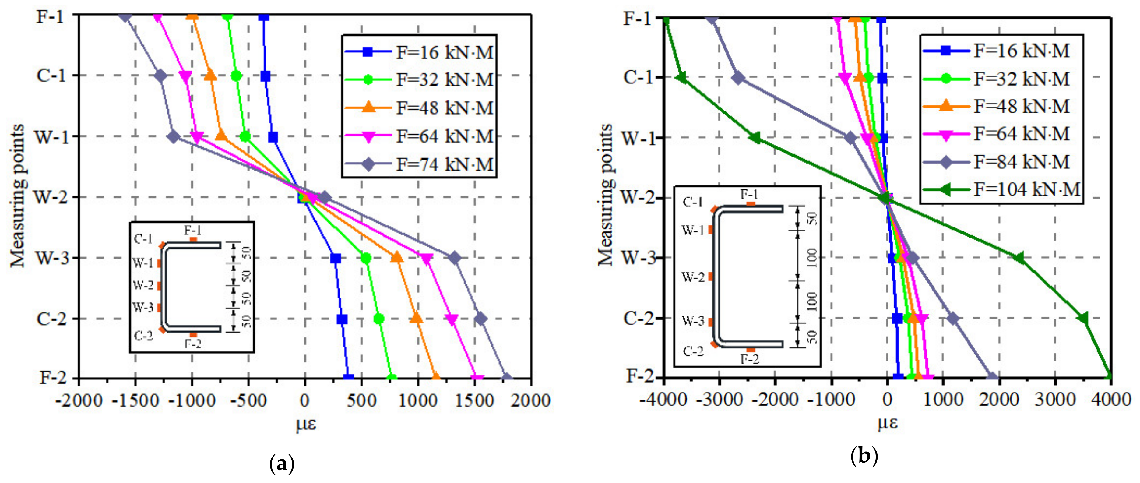
  • The sectional strain development of the cold-formed steel channels was kept consistent with hot-rolled components, while the singularity of stress distribution was produced when subjected to the vertical loads. The stresses at corner locations in the channel beam section were highly increased compared to that of flanges at the same deformation.
  • The component-based analytical model was established and verified, respectively, presenting the constitutive relationship of corner and flat parts of cold-formed steel channel beams.

Author Contributions

R.-G.L. designed and conducted the experiments, carried out the analytical procedure, written the manuscript. B.X. put forward the concept of the work and designed the investigation. F.Z. participated in the experiments and FE simulations. S.-N.P. made the contributions to the experiments and FE simulations. C.Y. participated in the FE simulations and theoretical derivations. M.-W.C. made the contributions to the analytical procedure and edited the language of the manuscript. S.-H.C. participated the FE simulations, validations and writing—review & editing; M.-Z.X. made the contributions to the visulization and writing—review & editing. All authors have read and agreed to the published version of the manuscript.

Funding

This work was financially supported by the National Natural Science Foundation of China (Grant No. 52208145).

Data Availability Statement

The data presented in this study are available on request from the authors.

Conflicts of Interest

The authors declare no conflict of interest.

References

  1. Afshan, S.; Rossi, B.; Gardner, L. Strength enhancements in cold-formed structural sections—Part I: Material testing. J. Constr. Steel Res. 2013, 83, 177–188. [Google Scholar] [CrossRef]
  2. Xu, B.; Xia, J.; Ma, R.; Wang, J.; Chen, X.; Chang, H.; Zhang, L. Investigation on True Stress-Strain Curves of Flat and Corner Regions of Cold-Formed Section Using 3D Digital Image Correlation Method. Adv. Civ. Eng. 2019, 2019, 3138176. [Google Scholar] [CrossRef]
  3. Lee, Y.; Lee, Y.; Tan, C. Experimental Investigation on Cold-Formed Steel Beams under Pure Bending. J. Teknol. (Sci. Eng.) 2012, 58, 13–20. [Google Scholar] [CrossRef]
  4. Ye, J.; Hajirasouliha, I.; Becque, J.; Pilakoutas, K. Development of more efficient cold-formed steel channel sections in bending. Thin-Walled Struct. 2016, 101, 1–13. [Google Scholar] [CrossRef]
  5. Schafer, B. Review: The Direct Strength Method of cold-formed steel member design. J. Constr. Steel Res. 2008, 64, 766–778. [Google Scholar] [CrossRef]
  6. Szymczak, C.; Kujawa, M. On local buckling of cold-formed channel members. Thin-Walled Struct. 2016, 106, 93–101. [Google Scholar] [CrossRef]
  7. Somodi, B.; Kövesdi, B. Flexural buckling resistance of cold-formed HSS hollow section members. J. Constr. Steel Res. 2017, 128, 179–192. [Google Scholar] [CrossRef]
  8. Hu, S.; Li, L.; Zhou, J.; Zhang, H.; Huang, N. Comparative Analysis on Strain Hardening of Thick-Wall Cold Formed Steel Tube with Square and Rectangular Hollow Section. J. Mater. Sci. Eng. 2010, 28, 76–80+129. [Google Scholar]
  9. Hu, S.; Li, L.; Zhou, J. Strain Hardening of Thick-Walled Cold Formed Steel Rectangular Hollow Section. J. Build. Struct. 2011, 32, 76–81. [Google Scholar]
  10. Wen, D.; Shen, Z.; Li, Y.; Zhu, S. Experimental Research on Cold-Formed Thick-Walled Steel Box Stubs and Comparison of Results with Related Codes. J. Tongji Univ. (Nat. Sci.) 2016, 44, 1190–1198. [Google Scholar]
  11. Li, Y.; Li, G.; Shen, Z.; Ma, Y.; Zhu, S. Modification Method for Yield Strength of Cold- Formed Thick- Walled Steel Sections Considering Cold- Forming Effect. J. Build. Struct. 2015, 36, 1–7. [Google Scholar]
  12. Fu, X.; Ren, H.; Wu, X. Study on Calculation Method of Yield Strength of Cold Formed Thick Wall Section Steel. Sci. Res. 2022, 44, 2243–2247. [Google Scholar]
  13. Tong, L.; Huo, T.; Hou, G. Research on Design Formula for Yield Strength of Cold-Formed Rectangular Steel Tubes with Medium-Thick Wall. J. Build. Struct. 2018, 39, 81–90. [Google Scholar]
  14. Cai, Y.; Ben, Y. Behavior of Cold-Formed Stainless Steel Single Shear Bolted Connections At Elevated Temperatures. Thin-Walled Struct. 2014, 75, 63–75. [Google Scholar]
  15. Huang, Y.; Ben, Y. Experimental Investigation of Cold-Formed Lean Duplex Stainless Steel Beam-Columns. Thin-Walled Struct. 2014, 76, 105–117. [Google Scholar]
  16. Ben, Y. Experimental and Numerical Investigation of High Strength Stainless Steel Structures. J. Constr. Steel Res. 2008, 64, 1225–1230. [Google Scholar]
  17. Ma, J.-L.; Chan, T.-M.; Young, B. Design of cold-formed high strength steel tubular beams. Eng. Struct. 2017, 151, 432–443. [Google Scholar] [CrossRef]
  18. Han, J.; Yang, F.; Yang, J.; Li, Z. Experimental Study and Analysis on Effect of Cold-Formed Procedures to Cold-Formed Thick-Walled Steel Members. Build. Struct. 2010, 40, 200–203. [Google Scholar]
  19. Wang, H.; Zhang, Y. Experimental and numerical investigation on cold-formed steel C-section flexural members. J. Constr. Steel Res. 2009, 65, 1225–1235. [Google Scholar] [CrossRef]
  20. Ayhan, D.; Schafer, B.W. Cold-formed steel member bending stiffness prediction. J. Constr. Steel Res. 2015, 115, 148–159. [Google Scholar] [CrossRef]
  21. Rossi, B.; Afshan, S.; Gardner, L. Strength enhancements in cold-formed structural sections—Part II: Predictive models. J. Constr. Steel Res. 2013, 83, 189–196. [Google Scholar] [CrossRef]
  22. Schafer, B.; Li, Z.; Moen, C. Computational modeling of cold-formed steel. Thin-Walled Struct. 2010, 48, 752–762. [Google Scholar] [CrossRef]
  23. Misiūnaitė, I.; Rimkus, A.; Jakuboskis, R.; Sokolov, A.; Gribniak, V. Analysis of local deformation effects in cold-formed tubular profiles subjected to bending. J. Constr. Steel Res. 2019, 160, 598–612. [Google Scholar] [CrossRef]
  24. Alireza, F.; Iman, M.; Seyed, M.; Jong, H. Force–Displacement Relationship of the Butterfly Shaped Beams Based on Gene Expression Programming. Int. J. Steel Struct. 2020, 20, 2009–2019. [Google Scholar]
  25. Alireza, F.; Iman, M.; Hamzeh, D. Incremental Dynamic Analysis for Estimating Seismic Performance of Multi-Story Buildings with Butterfly-Shaped Structural Dampers. Buildings 2019, 9, 78. [Google Scholar]
  26. Young, K.; Seyed, M.; Alireza, F.; Jong, H.; Iman, M.; Paul, A. Optimization of the Curved Metal Damper to Improve Structural Energy Dissipation Capacity. Buildings 2022, 12, 67. [Google Scholar]
  27. Alireza, F.; Mohsen, K.; Iman, M. Shape Optimization of Butterfly-Shaped Shear Links using Grey Wolf Algorithm. Ing. Sismica 2019, 36, 27–41. [Google Scholar]
  28. Alireza, F.; Matthew, R.E.; Jong, H. Effect of Flexural and Shear Stresses Simultaneously for Optimized Design of Butterfly-Shaped Dampers: Computational Study. Korea Sci. 2019, 23, 329–335. [Google Scholar]
  29. GB/T 228.1-2010; National Standard of the People’s Republic of China. Metallic Materials—Tensile Testing—Part 1: Method of Test at Room Temperature. China Standard Press: Beijing, China, 2010.
  30. Simulia. ABAQUS-6.14; Systems Simulia Corporation: Johnston, RI, USA, 2014. [Google Scholar]
  31. Luo, Z.; Shi, Y.; Xue, X.; Gao, T. Experimental and numerical investigation on patch loading capacity of longitudinally stiffened hybrid titanium-clad bimetallic steel plate girder. Eng. Fail. Anal. 2023, 146, 107117. [Google Scholar] [CrossRef]
  32. Wang, L.; An, Y.; Ding, F.; Kuang, Y.; Ma, Q.; Tan, S.; Zhang, W.; Zhao, P.; Ren, E. Numerical Investigation of Composite Behavior and Strength of Rectangular Concrete-Filled Cold-Formed Steel Tubular Stub Columns. Materials 2021, 14, 6221. [Google Scholar] [CrossRef]
Figure 1. Geometrical and dimensional details of cold-formed steel channel beams: (a) Geometrical details; (b) Dimensional details of beam sections.
Buildings 13 02149 g001
Figure 2. Descriptions of coupons extracted from corner and flat regions of cold-formed channel: (a) Flat coupon; (b) Corner coupon.
Buildings 13 02149 g002
Figure 3. Test set-up for tensile test: (a) Test equipment with DIC measuring system; (b) Speckle of coupons.
Buildings 13 02149 g003
Figure 4. Test set-up for bending test: (a) Test apparatus; (b) Arrangement of strain gauge in CFB-1; (c) Arrangement of strain gauge in CFB-2.
Buildings 13 02149 g004
Figure 5. Strain nephograms of flat and corner coupon: (a) Flat coupon; (b) Corner coupon.
Buildings 13 02149 g005
Figure 6. Nominal stress–strain curves of flat and corner coupons: (a) Flat coupons; (b) Corner coupons.
Buildings 13 02149 g006
Figure 7. Failure observations of cold-formed channel beam specimens: (a) CFB-1; (b) CFB-2.
Buildings 13 02149 g007
Figure 8. Comparison of experimental and numerical results: (a) Failure modes; (b) Mid-span moment-rotation curves.
Buildings 13 02149 g008
Figure 9. Mid-span moment-strain curves of beam specimens: (a) CFB-1; (b) CFB-2.
Buildings 13 02149 g009
Figure 10. Strain distribution of mid-span sections: (a) CFB-1; (b) CFB-2.
Buildings 13 02149 g010
Figure 11. FEA model of cold-formed steel channel beam assigned the different material property parameters: (a) Numerical model with geometry, mesh, load type and BCs; (b) Material parameters for flat region; (c) Material parameters for corner region.
Buildings 13 02149 g011
Figure 12. Longitudinal stress-rotation curves: (a) CFB-1; (b) CFB-2.
Buildings 13 02149 g012
Figure 13. Longitudinal stress development: (a) CFB-1; (b) CFB-2.
Buildings 13 02149 g013
Figure 14. Establishment of component-based models for cold-formed steel channel: (a) Stress distribution; (b) Component-based model.
Buildings 13 02149 g014
Figure 15. Comparison of moment- rotation curves from experimental and analytical results.
Buildings 13 02149 g015
Table 1. Parameters of engineering stress–strain curves.
Types of CouponsSpecimensσy (MPa)εyσu (MPa)εu
Flat couponsTF-1260.640.0013410.770.244
TF-2254.260.0012406.660.264
TF-3247.880.0012402.550.232
BF-1253.580.0013410.420.264
BF-2265.670.0013426.440.243
BF-3261.970.0012413.910.244
Corner couponsTC-1410.620.002437.990.013
TC-2383.750.002441.940.018
TC-3370.780.002441.350.02
BC-1380.780.002440.130.023
BC-2380.780.002443.230.024
BC-3395.220.002443.440.013
Average values of flat coupons257.330.0013411.790.249
Average values of corner coupons386.990.002441.350.0185
Note: (1) σy is the yielding strength; (2) εy is the yielding strain; (3) σu is the ultimate strength; (4) εu is the corresponding ultimate strain.
Disclaimer/Publisher’s Note: The statements, opinions and data contained in all publications are solely those of the individual author(s) and contributor(s) and not of MDPI and/or the editor(s). MDPI and/or the editor(s) disclaim responsibility for any injury to people or property resulting from any ideas, methods, instructions or products referred to in the content.

