Abstract
Chemical deterioration, including sulphate and acid attacks, is a major issue affecting the long-term durability of engineered cementitious composite (ECC) constructions that contact water from various sources, including groundwater, seawater, sewer water, and drinking water. This research enhances ECCs’ strength and resilience against chemical attack by combining cementitious composites with multiwalled carbon nanotubes (CNTs) and polyvinyl alcohol (PVA) fibre volume fractions using multiobjective optimization. The central composite design (CCD) of RSM was applied to generate thirteen mixes of different potential combinations of factors (multiwalled CNTs: 0.05% to 0.08%, PVA: 1–2%) and eight outcome responses were studied, although eight response models—six quadratic and two linear—were successfully designed and assessed using analysis of variance. The coefficients associated with R2 for all the models were exceptionally high, with values varying from 84 to 99 percent. The multiobjective optimization predicted the best outcomes and developed optimal values for both variables (CNTs: 0.05% and PVA: 1%). The results showed that, at 0.05% of CNTs in ECCs, an ultimate improvement of 23% in compressive strength was seen. Additionally, when CNTs are used to grow in the ECC matrix, the expansion owing to sulphate resistance and length change due to acid attack are both reduced. In addition, when the percentage of CNTs increases in ECCs, the weight loss and pH value owing to acid attack, as well as the rate of chloride permeability test results, are reduced. Furthermore, CNTs and PVA fibres with 0.05% and 1–1.5% concentrations offer optimal construction sector outcomes.
1. Introduction
Engineered cementitious composites (ECCs) are a subset of high-performance fibre-reinforced cementitious composites (HPFRCCs) considered to have an excellent ductility with a medium fibre content. ECCs are built with high mechanical, physical, and toughness attributes that remain intact under normal or extreme conditions, employing micromechanics-dependent theoretical methodologies [1,2]. For the concrete industry, an ECC is a composite material that may help with product efficiency, waste reduction, economic and environmental advantages, and durability [3,4]. ECCs are superior to other composites in terms of their ability to control crack depth as well as their resistance to fracture and ductility [5]. The reason for this is that ECCs are more likely to develop many uniform microcracks, which greatly increase their tensile strength and ductility in contrast to regular concrete [6]. When comparing ECCs to regular concrete, their high tensile strength is increased by 3–5% [7]. Studies show that their compressive strain is between 0.4 and 0.65 percent, their tensile strength is between 4 and 12 MPa, and their compressive strength is between 20 and 95 MPa [8].
There are advantages to utilizing ECCs over regular concrete, but there are also some disadvantages. To begin, the drying shrinkage of the ECC matrix is greater than that of conventional concretes, which causes less eigenstress in the composite. Since ECCs do not include any coarse particles, their elastic modulus will be lower than that of regular concrete, leading to greater strain at compressive strength achievement [9]. Furthermore, concrete buildings are continually exposed to harsh environmental conditions caused by a wide range of both natural and artificial contaminants. One of the leading causes of mortar and concrete degradation is sulphate action [10]. Sulphate ions combining with calcium aluminate hydrate and calcium hydroxide in cement cause the sulphate effects [11,12]. Ettringite and gypsum are the components responsible for the concrete’s expansions and cracks, which weaken and reduce its durability [9,13]. A decline in concrete’s durability may be traced back to sulphate expansion, although sulphate erosion of the primary phases of hydrate Portland cement, in particular calcium hydroxide and calcium silicate, also plays a role. As a result, the concrete’s strength and lifespan are shortened [13,14].
Another possible hazard to concrete is when it is attacked with acid. Acid attacks on concrete may occur in a variety of ways. Acids in groundwater or soil have the potential to dissolve underground concrete structures, either naturally or as a result of the disposal of industrial waste chemicals. In industrial settings, acid leakage and spontaneous spills are also possible [15]. Acid attack methods vary according to the kind of acid, with sulphuric, carbonic, hydrochloric, and nitric acids being the most commonly encountered acids in concrete. Therefore, the exposed concrete deteriorates when cement hydrates and calcium hydroxide dissolves as calcium salts. Acid attack is distinct from sulphate attack in that its decomposition does not require substantial expansion. Cement hydration products and carbonaceous materials (such as limestone and dolomite used in concrete production) are both sensitive to acidity [16]. Sulphuric acid (H2SO4), unlike other acids, has the potential to deteriorate and expand concrete. Numerous investigations have shown that exposing concrete to sulphuric acid causes it to lose mass. Concrete’s calcium hydroxide and calcium silicate hydrate gel combine with sulphuric acid to create gypsum. When gypsum corrodes, concrete deforms and collapses. Microbiological corrosion of concrete occurs when gypsum corrosion reduces the concrete’s alkalinity [17]. Early degradation, strength loss, and, in the worst situations, disintegration and collapse of the concrete structure are all caused by corrosion, which produces a weak composite with no cementitious competences. It is possible that gypsum will undergo yet another round of the reactions outlined in the sulphate attack section, leading to ettringite and/or thaumasite, during the second phase of sulphuric acid corrosion of concrete. When exposed to an acidic medium, however, ettringite and thaumasite quickly dissolve. Therefore, gypsum will result from the majority of the sulphuric acid reaction [18,19].
Several strategies have been explored in the literature to enhance concrete’s resistance to acid attack. These include reducing the concrete’s permeability and using mineral additives to control the production of calcium hydroxide during the hydration of cement [20]. Mortars and concrete with specified cement-to-mineral-admixture weight ratios have been developed so that the aforementioned effective methods may be used, and they have been shown to be rather successful in resisting sulphate attacks [21,22]. These nanoparticles are utilized in conjunction with certain mineral admixtures in concrete, which have been found to be efficient against sulphate and acid attacks [23,24]. The efficacy of a pozzolanic reaction may be easily seen since it is proportional to the surface area of amorphous nanoparticles. The free, leachable calcium hydroxide in concrete is reduced or eliminated by using a pozzolan, which also increases density and resistance to sulphate and acid attack [25]. Moreover, its filling impact must be taken into account as an added advantage. This study examined the impact of sulphate and acid attack on concrete that has been changed with different nanomaterials, including multiwalled carbon nanotubes (CNTs).
Nanomaterials are unique in nature and have many useful applications [26]. Carbon nanotubes (CNTs) have a Young’s modulus of one TPa and a tensile strength of 65–93 GPa, while having a specific weight of one-sixth that of steel [26]. The use of these fibres has been proven by researchers to have the potential to significantly enhance the mechanical properties and durability of cement-based products [27,28,29,30,31]. By obstructing nano cracks and promoting bridging between them, CNTs may be put to practical use to increase load-carrying capacity and ductility [28,32,33]. In the majority of experiments, CNT-reinforced cement-based materials outperformed control samples in terms of mechanical properties, electrical conductivity, and thermal conductivity [34,35,36]. CNTs play a crucial role in cement-based composites by improving crack resistance, fracture properties, and concrete qualities, including bearing tension and flexure [37,38,39]. Addressing the close relationship between durability and microstructure, it should be noted that CNTs have a beneficial impact on the long-term stability of cement-based components by filling pore spaces, minimizing porosity, and bridging pores. By reinforcing the feeble connection of the cementitious materials’ matrix, the introduction of CNTs has the ability to mitigate the challenges related to the widespread implementation of an ECC as well as the damaging effects of sulphate attack and acid attack. Using RSM modelling and optimization, the main purpose of the current research was to assess the compressive strength, rapid chloride penetration test (RCPT), and resistance to acid and corrosive attacks of an ECC incorporating variable quantities of PVA fibres and multiwalled CNTs.
2. Materials and Methods
2.1. Materials
In order to produce ECC that complies with ASTM C150 [40], Portland cement (PC) was used as a binding agent while class F fly ash (FA), that complies with ASTM C618 requirements, was used in this research [41]. Table 1 lists the specific gravity, Blaine fineness, and X-ray fluorescence spectroscopy (XRF) results for PC and FA. Although natural river sand was utilized in this work as fine aggregate that proceeded through the #4 mesh (less than 4.75 mm in size), multiwalled carbon nanotubes (MWCNTs) are utilized as additive ingredients in the ECC in varying proportions and the properties of MWCNTs are displayed in Table 2. Furthermore, the volume proportion of the ECC composition used the polyvinyl alcohol (PVA) fibre produced in Japan by Kuraray as a fibre component. The outermost layer of the fibre was treated with 1.2% oil by weight to alter the fibre/matrix interaction characteristics. Table 3 provides a description of the fibre’s attributes. The ECC combination also included a modified polycarboxylate-based high-range water reducer as a kind of superplasticizer (SP) with pH and specific gravity of around 6.2 and 1.08, respectively. In the ECC combination, it was incorporated at 0.99% by weight of PC. In the continuing investigation, potable water was also employed for mixing and curing.

Table 1.
XRF of PC and FA.

Table 2.
Properties of multiwalled carbon nanotube [42,43,44].

Table 3.
Properties of polyvinyl alcohol fibre.
2.2. Research Mix Proportions Developed by RSM
This study utilized the RSM method to examine the effects of multiwalled CNTs and PVA on various composite materials. The input factors were multiwalled CNTs and PVA at three different concentrations (0.05, 0.065, and 0.08% by weight of PC, and 1%, 1.5%, and 2% of PVA fibre by volume fraction), with a water-to-binder ratio of 0.30 for all ECC combinations. However, the mix proportions were used for the most commonly utilized ECC in a large number of research investigations (ECC-M45) [45,46]. A 1.0% superplasticizer was used as a chemical admixture. Thirteen trial designs were created using the RSM central composite design (CCD) method, involving five randomly repeated instances of each component and various combinations and proportions of input parameters. The duplicate mixes were used to verify the validity of the investigation and prevent potential changes. The RSM also evaluated how input element relationships affected responses, including compressive strength, the rapid chloride permeability test (RCPT), and durability behaviours due to sulphate attack and acid attack. The mix proportion of the study is summarized in Table 4.

Table 4.
Mix proportion of multiwalled CNT-ECC generated by RSM.
2.3. Mixing and Sample Preparation
In this research, the multiwalled CNT–ECC combination mixing configuration was used. Sand, PC, and FA were loaded into the drum of the concrete mixer at the same time and mixed for about two minutes in a dry condition. After that, the predetermined quantity of water, multiwalled CNTs, and 1% SP were added while the mixer kept on rotating; it required a further two to three minutes for the mixture to become homogenous after this process. To help the multiwalled CNTs disperse during the sonication process, polycarboxylate-based SP was used with the multiwalled CNTs. The PVA fibre was then thoroughly included in the rotating mixer and mixed for an additional two to three minutes to evenly distribute the fibres. SP was incorporated into combinations with a high multiwalled CNT content to compensate for the decrease in flowability and create a workable solution. A number of specimens constructed from the freshly mixed concrete were tested for compressive strength, sulphate attack, acid attack, and RCPT.
2.4. Testing Methods
2.4.1. Compressive Strength
Cube-shaped samples (50 mm × 50 mm × 50 mm) were produced of multiwalled CNT–ECC to test the compressive strength at 28 days by confirming the BS EN 12390-3 [47] requirements.
2.4.2. Durability Properties Due to Acid Attack
The cube-shaped samples (50 mm × 50 mm × 50 mm) and prisms (285 mm × 25 mm × 25 mm) were submerged in a 5.0% sulphuric acid (H2SO4) solution for 28 days, and then cubical samples were tested for weight loss and compressive strength due to acid attack by following the ASTM C1898-20 and BS EN12390-3, respectively, while the prisms were tested for change in length due to acid attack under the ASTM C157-08. A weighing machine was used for measuring the weight loss, compression machine used for determining the compressive strength, and vernier calliper was applied for measuring the change in length of prism. In addition, the exterior moisture on the multiwalled CNT–ECC sample was evaporated and removed after 28 days of standard curing. Monitoring the pH readings of three ECC samples paired with various concentrations of multiwalled CNTs obtained a measurement of pH by obeying the ASTM F 710 code procedure. The multiwalled CNT–ECC cube samples were crushed into a fine powder, and a total of ten grammes of the powdered form were immersed in one hundred millilitres of distilled water and agitated for a duration of ten minutes. The pH of the liquids was then determined using a pH meter.
2.4.3. Durability Properties Due to Sulphate Attack
The cube-shaped samples (50 mm × 50 mm × 50 mm) and prisms (285 mm × 25 mm × 25 mm) were submerged in a 5% sodium sulphate (Na2SO4) solution for 28 days, and then cubes were used to monitor the weight gain and compressive strength due to sulphate attack by applying the ASTM C1012 and BS EN12390-3, correspondingly, while the prisms were tested for expansion under the ASTM C1012. A weighing machine was used for measuring the weight loss, compression machine used for determining the compressive strength, and vernier calliper was applied for measuring the expansion of prism.
2.4.4. Rapid Chloride Permeability Test (RCPT)
Cylindrical concrete disc samples measuring 100 × 50 mm were initially wet-cured for 28 days prior to the RCPT test. Rapid chloride permeability test protocols from AASHTO T277-15 [48] and ASTM C1202-19 [49] were used in the studies. Firstly, quick-setting epoxy glue was applied to the concrete pieces’ edges. After allowing the glue-like coating to fully dry, the cylindrical specimen was placed in a vacuum chamber for three hours or until it was no longer sticky when contacted. The cylinder was then placed into the testing device, with two unique cells interacting with the two untreated surfaces of the disc. The cell having 0.3 N sodium hydroxide (NaOH) in distilled water acted as the cathode, while the cell comprising 3% (by weight) sodium chloride (NaCl) combination acted as the anode. The monitoring device was then connected to a 60-volt DC potential difference that was monitored and maintained for a period of six hours. Every 30 min throughout the six-hour assessment, the total charge transported—measured in coulombs—was observed. The device determined and recorded the total amount of electric charge (measured in coulombs) that passed throughout the disc sample. According to the investigators’ prior study [50], this total charge represents the quantity of chloride ions that penetrated the ECC samples under examination. Figure 1 depicts the laboratory assessment setup.
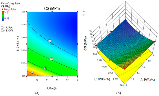
Figure 1.
Experimental testing setup: (a) compressive strength, (b) weight loss, (c) pH test, (d) change in length, and (e) RCPT.
3. Results and Discussions
3.1. Compressive Strength of CNT-ECC
The compressive strength of samples cured for 28 days, generated from ECC mixtures including varying amounts of multiwalled CNTs, is shown in Figure 2. The compressive strength of ECC mixed with 1% PVA fibre is highest at 74.27 MPa when using 0.05 percent multiwalled CNTs as the nanomaterial, while this strength drops to 55.18 MPa at 0.08 percent CNTs after 28 days, respectively. Similarly, the highest compressive strength is observed at 65.96 MPa at 0.05 percent multiwalled CNTs, and the lowest strength is recorded at 53.77 MPa at 0.08 percent multiwalled CNTs in cementitious composites reinforced with 1.5% PVA fibre at 28 days. The compressive strength of ECC reinforced with 2% PVA fibre and varying concentrations of carbon nanotubes also followed this trend. As shown in Figure 2, the build-up of 0.5% multiwalled CNTs in the ECC mixture yields excellent results on day 28 of curing. Multiwalled CNTs are responsible for the increased compressive strength of ECC because they fill up the voids left by the other components [51]. Previous research by Lu et al. [52] and Yang et al. [53] demonstrates that the carboxylic acid of nanoscale particles chemically interacts with the Ca(OH)2 or C-S-H of the cementitious matrix. Putting “template influence” [54] to use might change the distribution channels for hydration production. Cement hydration may be kicked off with the help of a carbon nanomaterial. Interfacial adhesion with Ca2+ ions from the C-S-H system may be significantly increased, as predicted by molecular mechanics simulations, for carbon-based nanoscale materials containing functional groups on their basal planes [55]. These qualities further solidify the bond between the nanocarbon and the cement. By enabling stress to be transported from one area to another, the compressive strength of the ECC mixture is increased. The compressive strength of ECC mixtures including CNTs at concentrations greater than 0.05 percent declines with each curing cycle. Since multiwalled CNTs are dispersed as nanomaterials throughout the cement matrix at higher dosages, their optimum action in increasing the physical strength of the cement matrix is delayed. This was first proposed by Eftekhari and afterwards developed by Mohammadi Research [56]. It shows that adding carbon nanotubes to concrete improves its mechanical and dynamic impact qualities. Carrico et al. [29] High-CNT concrete with a low aspect ratio was proposed to last longer [29]. It was shown that the addition of multiwalled CNTs to UHPC significantly increased the stiffness of C-S-H bonds. This suggests that a closer match between the hydration components may be possible with the use of multiwalled CNTs. According to Liew et al. [57], CNT modifies the microstructure and reduces the overall porosity of the cement matrix. The three roles that carbon nanotubes play in bridging, pore filling, and nucleation are largely responsible for this. Yakovlev et al. [58] studied CNTs produced from aromatic hydrocarbons for their potential to reinforce Portland cement foam concrete. Research suggests that adding only 0.5% CNTs may significantly improve compressive strength and lower heat conductivity by up to 20%. Carbon nanotubes, as reported in the scholarly literature, have remarkable mechanical characteristics [59,60].
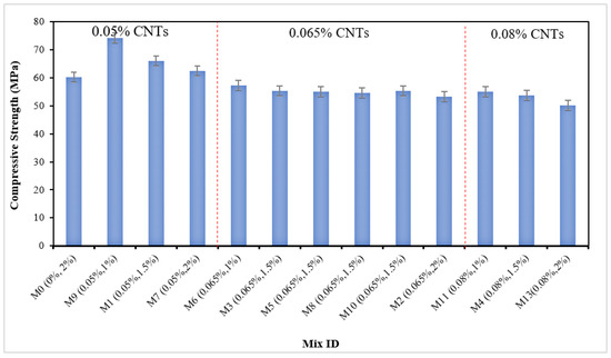
Figure 2.
Compressive strength of multiwalled CNT–ECC.
3.2. Weight Loss Due Acid Attack
The weight loss caused by acid attacks was treated using cubical specimens constructed of multiwalled CNTs and ECC. Each specimen’s weight loss was tracked for a period of one month, and the results are shown in Figure 3. Nevertheless, on average over 28 days, the greatest weight loss of multiwalled CNT–ECC with 2% of PVA fibre added was 10.20% at 0.08% of multiwalled CNTs, whereas the lowest weight loss of multiwalled CNT–ECC with 1% of PVA fibre added was 5.10% at 0.08% of multiwalled CNTs. According to reports, the least amount of weight loss from an acid attack occurs when 1% PVA fibre by volume is used to produce multiwalled CNT-ECC, as opposed to multiwalled CNT-ECC that is mixed with 1.5% and 2% PVA fibre. Additionally, compared to the other trial mix proportions, the M2, M4, M7, M8, and M13 trial mixes showed a greater rate of weight reduction. The alkaline nature of multiwalled CNTs and ECC makes them vulnerable to acidic attacks. Calcium salts are created when acid and calcareous materials mix. The salts result in a reduction in the cement’s matrix cohesiveness and ECC density. A brittle gel is formed when sulphuric acid reacts with calcium-silicate-hydrate (C-S-H) gels, weakening the multiwalled CNT-ECC. Additionally, gypsum and ettringite will be produced as reaction by-products depending on the makeup of the dispersed calcium salts (i.e., calcium sulphate). The hydration process of the ECC combination was accelerated by the presence of these reaction by-products, which increased the density of the ECC. The porosity of the ECC was further decreased using ettringite and gypsum. In this case, when exposed to acidic circumstances, ECC puts on a little weight [61]. Equations (1) and (2) describe the process that takes place when ECC is exposed to a sulphuric acid solution [62].
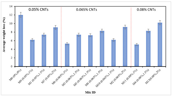
Figure 3.
Weight loss of multiwalled CNT-ECC due to acid attack.
Considering the way the two factors, PVA and multiwalled CNTs, change in percentage might help explain the results of this investigation. Higher PVA fibres were present in the ECC, which led to the breaking down of the samples and deeper penetration of acidic fluids. However, a lower weight loss due to degradation occurred in the ECC with a smaller percentage of PVA combination added because fewer cracks emerged and the component parts were less easily detached. When the ECC was subjected to harsh circumstances, such as acidic surroundings, the multiwalled CNTs in the combination also aided in improving its durability and efficiency. Lesser multiwalled CNTs in the combinations resulted in greater weight loss due to ECC deterioration, while greater multiwalled CNTs made the combinations more resilient. By comparing mixes with 1% PVA concentrations but different multiwalled CNTs levels, it was shown that the higher multiwalled CNT levels produced better weight loss results.
3.3. Change in Length Due to Acid Attack
The ECC prisms with different quantities of multiwalled CNTs added underwent the acid attack examination. After 28 days, the length had changed. It was revealed how samples that were subjected to acid attacks at different intervals changed in length. The samples’ differences in length serve as a more powerful indication of deterioration. The specimens were removed after being immersed in the acid mixture for 28 days, dried, and having additional loose material scraped off the surface with a wire brush. Vernier callipers were used to measure the length fluctuations of the surface-cleaned specimens. Figure 4 illustrates how the samples’ lengths are taken into account when applying digital vernier callipers prior to being submerged in the acid mixture. Based on changes in the physical appearance and alteration in the dimension over a 28-day exposure period, the acid resistance was assessed. However, the measurement of the length of prism specimens prior to and following submersion in a 5% sulphuric acid mixture dispersion after 28 days was compared to determine the average change in length. The increase or decrease in percentage was then calculated. The results show that, although M7 (0.05% multiwalled CNTs and 2% PVA) had the maximum expansion as assessed by the variation in length at a rate of 0.90%, M11 (0.08% multiwalled CNTs and 1% PVA) had the least average rate of change in length at 0.30%. Additionally, M1 (0.065% multiwalled CNTs and 1.5% PVA fibre), M2 (0.065% multiwalled CNTs and 2% PVA), M3 (0.65% multiwalled CNTs and 1.5% PVA fibre), and M7 (0.05% multiwalled CNTs and 2% PVA fibre) all showed greater changes in length after 28 days in the making of ECC but their values were lower than the reference mixture. Similar characteristics were seen for ECC combinations that had different proportions of crumb rubber and GO as fine substitutes. However, the GO greatly lessened the length change [63]. The presence of PVA fibre at levels of 1%, 1.5%, and 2%, as well as the proportion of multiwalled CNTs present in the range of concentrations of 0.05% to 0.08%, may be used to explain these results. Mixtures with a higher PVA content show a bigger change in length due to the existence of micropores surrounding the sample surface, which allow for increased absorption of submerged media. The quantity of micro-voids increases with PVA concentration, which causes a higher length shift. This is in line with the investigation’s finding that ECC combinations with over one percent PVA saw more variation in length than the reference specimen. Additionally, since the multiwalled CNT dosage was resistant to the media’s penetration by the acidic environment in the ECC, it exhibited good impacts on reducing the length change of the ECC. Furthermore, ECC with multiwalled CNT reinforcement resisted disintegrating more when exposed to acid. The CNT-ECC exhibits better results in terms of resistance to acid after 28 days. Similar remarks have been presented by Gu, Bennett, and Visintin [64], as well as by Chintalapudi and Pannem [65].
3.4. Compressive Strength Due to Acid Attack
Figure 5 displays the results of a compressive strength study performed on ECC specimens that were subjected to an acidic attack for 28 days. A test for strength qualities following an acid attack is particularly crucial for establishing the severity of the acid attack’s influence and the deterioration rate of the manufactured multiwalled CNT-ECC specimens. A compressive strength measurement was performed on specimens that had been immersed in a 5% sulphuric acid solution for 28 days. Figure 5 depicts the mean compressive strength of control samples and those subjected to a 28-day acid attack, as well as the percentage drop in compressive strength. A maximum of twelve percent of the compressive strength of a typical reference specimen was reduced. After 28 days, the acid attack reduced the compressive strength of the ECC with 1% PVA added to levels as low as 3.45% for 0.05% multiwalled CNTs. The compressive strength drops in the multiwalled CNT-ECC specimens, which included 0.05% CNTs by weight of cement, was reduced after 28 days of acid exposure. Furthermore, the use of multiwalled CNTs increases in the ECC gave lower strength degradation from acidic attack than the compressive strength of the standard ECC combination. Furthermore, the incorporation of 0.05 percent multiwalled CNTs into the ECC combination boosted hydration in mechanical properties such as compressive strength. Furthermore, after 28 days of acid attack, the multiwalled CNT-ECC specimen demonstrated higher resistance to both deterioration and compressive force resistance. Multiwalled CNT-ECC specimens containing 0.05 percent multiwalled CNTs showed a 3.45 percent decrease in compressive strength. The use of combination multiwalled CNTs in ECC compositions led to a considerable reduction in deterioration and an increase in sulphuric acid resistance. Furthermore, the reduction of compressive strength in acid-attacked specimens of concrete was attributable to an increase in micro-voids and porosity [66]. Aiken et al. [67] and Chintalapudi and Pannem [65] observed similar results.
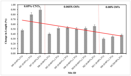
Figure 4.
Change in length of multiwalled CNT-ECC due to acid attack.
Also, the usage of multiwalled CNTs increases in the ECC combination offers less strength loss from acidic attack than the reference mixture’s compressive strength. In addition, the accumulation of 0.05 percent multiwalled CNTs in the ECC mixture increased hydration in mechanical characteristics, including compressive strength. In addition, when exposed to 28 days of acid attack, the multiwalled CNT-ECC sample exhibited superior resistance to degradation and compressive force resistance. The multiwalled CNT-ECC samples with a 0.05 percent multiwalled CNT concentration exhibited a 3.45 percent reduction in compressive strength loss. The incorporation of composite multiwalled CNTs in ECC formulations resulted in a significant decrease in degradation and an improvement in sulphuric acid resistance. In addition, the loss of compressive strength is attributed to a rise in micro-voids and porosity in acid-attacked concrete samples [66]. Similar findings were reported by Aiken et al. [67] and Chintalapudi and Pannem [65].
3.5. pH Test
Given that embedded steel only demonstrates long-term endurance at a pH reading of 9 or higher, measuring the ECC’s pH value is essential for assessing acidic attacks that might severely injure reinforced concrete. As shown in Figure 6, the pH levels of the concrete specimens produced by ECC with 0.05% to 0.08% of multiwalled CNTs added were measured continuously for 28 days. When multiwalled CNTs were added at concentrations of 0.05%, 0.065%, and 0.08% over the course of 28 days, the pH of ECC with 1% PVA fibre added was less than the reference combination at 9.80, 9.71, and 9.25 correspondingly. In the same way, the pH result was measured at 10.10, 9.96, and 9.52 at 0.05%, 0.065%, and 0.08% of multiwalled CNTs in ECC with 1.5% of PVA fibre added, which exhibits lower pH levels when contrasted with the reference combination at 28 days respectively. The incorporation of 1% PVA fibre in the ECC accumulation with the addition of multiple multiwalled CNTs has been shown to provide a lower pH reading than the utilization of 1.5% PVA fibre in the synthesis of ECC with the introduction of multiple multiwalled CNTs.
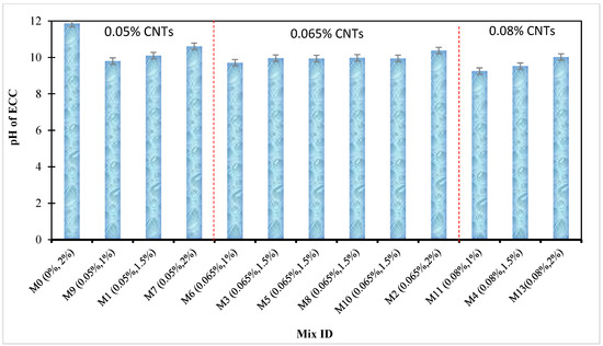
Figure 6.
pH value of multiwalled CNT-ECC due to acid attack.
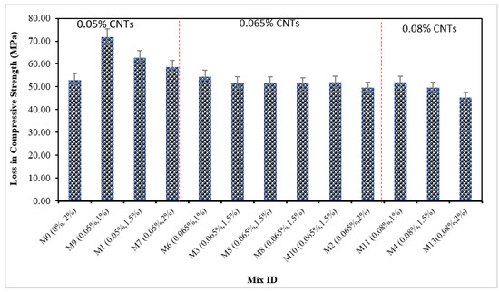
Figure 5.
Compressive strength of multiwalled CNT-ECC due to acid attack.
Moreover, the pH of ECC mixed with 2% PVA fibre measured 10.61, 10.38, and 10.02 when utilizing 0.05%, 0.065%, and 0.08% of multiwalled CNTs, and these pH levels for all combinations were constantly decreasing over the course of 28 days relative to the reference combination. Observations suggest that the synthesis of ECC, which incorporates a variety of multiwalled CNT contents, results in a rise in the pH level; however, these pH readings were all reported to be smaller than those of the control combination. Furthermore, whenever the amount of multiwalled CNTs in the combination grows, the pH measurement for ECC supplemented with various contents of PVA fibre decreases.
In addition to the filling action of multiwalled CNTs, that closes the pores of the ECC and prevents acid attack and environmental influence on the ECC, leading to decreasing pH levels, the pH reading of the ECC with a varied quantity of PVA fibre added decreased. Wan et al. [68] claim that carbonation lowers the pH from about 13.2 to as low as 8.0. The finding is that carbonation liberates bound chloride in addition to lowering pH. This is among the most obvious causes of the combined impact of carbonation and chloride intrusion, which accelerates the corrosion of steel and shortens the operational life of reinforced concrete structures. The pH level of concrete increased and then gradually decreased as the proportion of nanomaterial substitution increased up to 2%, as shown by Kumari et al. in their study [69]. Similar observations were made by Zeng et al. [70].
3.6. Rapid Chloride Penetration Test (RCPT)
One of the goals of this research was to look at how nanoparticles affect the way that ECC transports water. This led to the comparison and study of the effects of water movement on diffusion rates. The different hydration products ought to bind to the chloride ions as they infiltrate the mortar or ECC. As a result, the overall chloride ions that penetrate the ECC combination are made up of both bound and free chloride ions that are present in the pore spaces [71]. Rust is caused by free chloride ions that enter rebar via ECC pores and begin to move through it. In the current investigation, the acid-soluble chloride (total chloride), in accordance with ASTM C1202 [49], that is dependent on two factors, such as the w/c ratio and the chemical properties of the concrete, was calculated as the chloride penetration.
The delivered current released in 6 h was measured in this research to determine the permeability to chloride. Figure 7 shows the RCPT readings of the charge released by ECC after it had been hydrated for 28 days. The RCPT readings at 28 days varied from 799 to 1650 coulombs for the reference combination and the mixture including multiwalled CNTs with low chloride permeability in accordance with ASTM C1202 [49]. Additionally, the charge on the ECC combination was dramatically reduced by the incorporation of multiwalled CNTs. Additionally, the chloride ion permeability was decreased when ECC was synthesized with a greater multiwalled CNT content. After 28 days, the RCPT rates of the ECC combination combined with 1% PVA fibre were 1012 coulombs, 860 coulombs, and 799 coulombs, correspondingly, with 0.05%, 0.065%, and 0.08% of multiwalled CNTs. These readings are much lower than those obtained for the control combination of ECC. According to the RCPT reading for ECC with 1.5% of PVA fibre added, the RCPT rate of ECC with 0.05%, 0.065%, and 0.08% of multiwalled CNTs added was measured at 1198 coulombs, 1097 coulombs, and 943 coulombs, respectively, which are lower values than the control mix after 28 days.
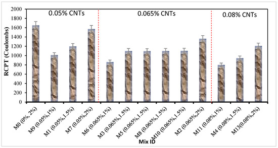
Figure 7.
Rapid chloride penetration test of multiwalled CNT-ECC mixture.
Additionally, after a period of 28 days, the RCPT measurements of the ECC combination were reduced by 4.80%, 17.50%, and 26.80%, correspondingly, compared to the control specimens when it was mixed with 0.05%, 0.065%, and 0.08% of PVA fibre. Experts have discovered that increasing amounts of multiwalled CNTs are used in the production of ECC, which lowers the combination’s RCPT. The microstructural expansion and reduced microporous interrelationships of ECC are responsible for this decline in RCPT readings. It was hoped that multiwalled CNTs would have the ability to form a packed, compacted microstructure with improved resistance to chloride entry. Nanoscale materials including SnO2, ZrO2, and CaCO3 may be utilized to calculate the RCPT in self-compacting mortar, according to Khotbehsara et al. [71]. However, when the quantity of CNTs increased up to a certain limit, the RCPT value declined. As previously mentioned, CNTs act as fillers to close gaps and boost the structure’s density. Additionally, they speed up hydration. As a consequence, pore structure development occurs faster and less chloride ion movement occurs. These results show that cement mortars must include CNTs to boost their resistance to chloride ion penetration. The rate of diffusion is reduced as a consequence of a portion of the chloride ions interacting and binding with the cement-based matrix. According to Schwarz and Neithalath [72], the mixtures of concrete containing glass powder had lower chloride permeability than the control sample. According to Miyandehi et al. [73], copper oxide nanoparticles greatly decreased the quantity of transferred charge.
3.7. Weight Gain Due to Sulphate Attack
Sulphate resistance tests were performed on ECC samples with 1%, 1.5%, and 2% PVA fibre added, and different concentrations of multiwalled CNTs. The experiment was carried out on specimens submerged in a 5% sodium sulphate solution. Sulphate resistance was assessed based on changes in physical appearance and weight at 28 days. For comparison, samples were also immersed in distilled water. Following 28 days of treatment with sodium sulphates, multiwalled CNT-ECC samples showed minute alterations. Figure 8 depicts the weight fluctuations in multiwalled CNT-ECC samples treated with sodium sulphate for as long as 28 days. The outcomes of the sulphate attacks on the proportionate change in weight of specimens of the control mix of ECC and the ECC combination including varying concentrations of multiwalled CNTs after 28 days of treatment are shown in Figure 8. The percentage rise in weight for the ECC combination without adding multiwalled CNTs was rather substantial. Nevertheless, the weight gain of an ECC combination containing 1% PVA fibre decreased when the quantity of multiwalled CNTs in the combination increased to 0.08% after 28 days. This decrease in mass variation of ECC mixed with 1% PVA fibre is due to the multiwalled CNTs that cover the gaps in the pores and render ECC tough, resulting in less sulphate attack infiltration in the multiwalled CNT-ECC sample. The decrease in percentage variation in mass might be attributed to the function of the wick, which allows the sulphate mixture to permeate the concrete through transportation and capillary movement. By vaporizing the sulphate ion crystallized on the concrete’s exterior section, it discloses and damages the surface. Furthermore, the mass growth of ECC combinations incorporated with 1.5% and 2% PVA fibre increases as the amount of multiwalled CNTs increases in ECC; however, the weight gain for all multiwalled CNT-ECC mixes reduced after 28 days in contrast to the reference mixture. This increase in weight change is due to an increase in PVA fibre concentration in ECC, leading to microscopic cracking in the samples and enabling sulphate media to pass through. However, in the ECC with a smaller amount of PVA combination added, there were smaller cracks and the individual elements were less easily separated, contributing to a smaller percentage of weight change due to degradation. When subjected to harsh circumstances, the multiwalled CNTs in the combination also contributed to increasing the ECC’s durability characteristics. In addition, the combinations containing fewer multiwalled CNTs had a greater percentage weight increase of GO-ECC added with 1% PVA fibre due to ECC destruction, while those containing more multiwalled CNTs were more durable. When comparing mixes with 1% PVA concentrations but varying multiwalled CNTs levels, the higher multiwalled CNT level produced improved weight change results. The same types of investigations were conducted by Devi et al. [74] and Luhar et al. [75].
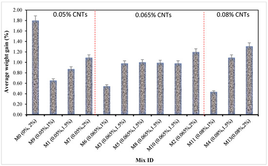
Figure 8.
Weight gain of multiwalled CNT-ECC due to sulphate attack.
3.8. Expansion Due to Sulphate Attack
Figure 9 depicts the results of ECC matrix accumulation growth owing to sulphate attack with various multiwalled CNT concentrations. The average amount of expansion, on the other hand, was determined through the comparison of the length of prism specimens immediately prior to and following submersion in a 5% sodium sulphate solution dispersion after 28 days. The rate of increment was then calculated. Based on the data, M11 (0.08% multiwalled CNTs and 1% PVA) had the least average rate of growth at 0.0027%, whereas M1 (0.05% multiwalled CNTs and 1.5% PVA) had the most expansion at 0.0069%. Furthermore, M1 (0.05% multiwalled CNTs and 1.5% PVA fibre), M2 (0.065% multiwalled CNTs and 2% PVA fibre), and M7 (0.05% multiwalled CNTs and 2% PVA fibre) showed the largest growth in ECC formation after 28 days. ECC mixes with varied proportions of carbon-based ingredients and crumb rubber as fine replacement components showed similar tendencies. Nevertheless, the carbon-based material greatly minimized the length change [63]. These findings can be determined by the presence of PVA fibre at levels of 1%, 1.5%, and 2%, along with a proportion of multiwalled CNTs ranging from 0.05% to 0.08%. A combination with a higher PVA concentration expands more due to the existence of micropores surrounding the sample surface, resulting in increased absorption of submerged media. The greater the quantity of PVA there is in a combination, the more micro-voids there are, resulting in more expansion. This is in line with the investigation’s result that concrete compositions comprising above one percent PVA expanded more than the control specimen.
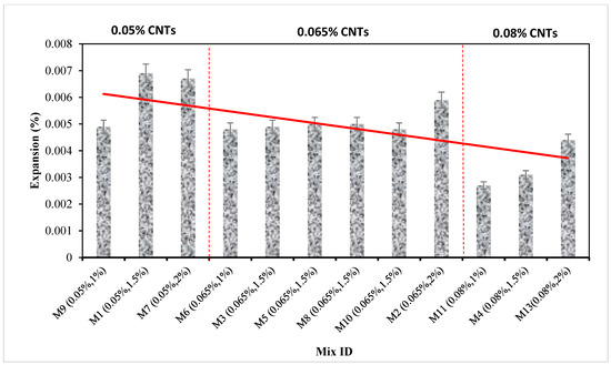
Figure 9.
Expansion of multiwalled CNT-ECC due to sulphate attack.
Furthermore, the multiwalled CNTs dosage had a favourable impact on reducing concrete expansion due to the fact that it was resistant to medium penetration by the sulphate solution in ECC. Because of the better adsorption capacity of multiwalled CNTs across broad surface areas, the electrical resistivity of ECC adding multiwalled CNTs increased throughout the disintegration and development stages owing to a decrease in free water. The rise in solid hydration by-products and reduction in porosity after hydration are likely to obstruct the ions’ conducting paths in the multiwalled CNT-ECC, raising resistance. A larger multiwalled CNT concentration may reduce the impacts of concrete expansion owing to the infiltration of sulphate solution. Another element leading to a rise in length change was the formation of fractures and holes containing ettringite on the exterior of the cement-based composite [76,77]. In addition, the production of ettringites, which employ a greater area, causes the expansion and cracking behaviours of ECC [78]. This is in accordance with previous research on the effect of sulphate on cement and concrete [61,79].
3.9. Compressive Strength of Multiwalled CNT-ECC Due to Sulphate Attack
Measurements were made of the reduction in compressive strength of sulphate-attacked ECC and comparisons were made with samples of unaffected sulphate that were subjected to a 28-day water cure. The final result is shown in Figure 10. The reduction was only up to 0.05% multiwalled CNTs as compared to the control mix and after 28 days there was a noticeable decline in the 6.80% in the reference combination. At 28 days, frequently, the reduction in compressive strength of the ECC combination mixed with 1% was measured by 3.40%, 4%, and 4.70% at 0.05%, 0.065%, and 0.08% of multiwalled CNTs. In the same manner, after 28 days, utilizing 0.05%, 0.065%, and 0.08% of multiwalled CNTs in ECC results in a 3.90%, 4.20%, and 5.02% reduction in the strength of the ECC mixed with 1.5% of PVA, respectively. The multiwalled CNT-ECC is reinforced with 2% PVA fibre and follows the same pattern. The results show that 0.05% of multiwalled CNTs could offer substantial defence against a sulphate attack.
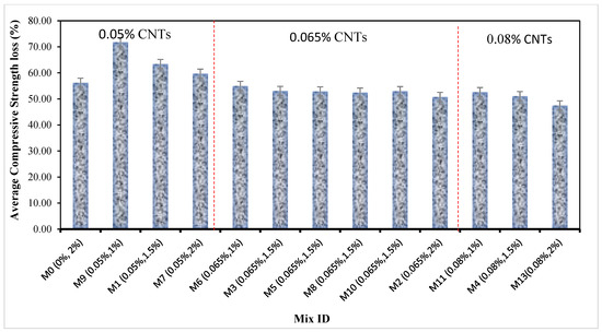
Figure 10.
Compressive strength of multiwalled CNT-ECC due to sulphate attack.
Additionally, owing to physical harm and the unintended chemical destruction of the combination, ECC function often deteriorates and the period of submersion is increased when exposed to a chemical attack. Figure 10 demonstrates how the presence of multiwalled CNTs improved the defence against sulphate attack. After being attacked by sulphates for 28 days, the compressive strength of combinations of concrete was assessed and the findings were compared to combinations that had been water-cured. The strength variance between combinations that were water-cured and those that were sulphate-treated was used to determine the strength drop. Figure 10’s results show that each of the mixtures decreased in strength. The reduction was found to be greater when the multiwalled CNT-ECC mixes were paired with the reference ECC combination. Furthermore, the sulphate attack caused the calcium components in C-S-H gels to escape, reducing composite toughness and causing the samples to degrade [80]. On the exterior of the concrete sample, Honglei et al. [81] found two distinct layers of gypsum with barely detectable amounts of ettringite and monosulphate. In contrast to fractures and swelling, sulphate attack is defined by a reduction in strength and adhesion [82]. Most of the mixes showed sulphate behaviour, which diminished their potency. The results are similar to those that Khan et al. [83] and Behfarnia and Farshadfar [84] observed.
4. Predictive Model Developments Using Response Surface Methodology (RSM) and Optimization
4.1. Analysis of Variance (ANOVA)
RSM was implemented to build response surface models that were then tested utilizing analysis of variance (ANOVA). The durability characteristics of ECC composites involving 0%, 0.05%, 0.065%, and 0.08% multiwalled CNTs, and varying PVA fibre concentrations were investigated for RSM modelling and optimization. Furthermore, quadratic approaches were shown to be most appropriate for compressive strength (CS), length change, CS due to acid attack, pH test, quick chloride penetration test, weight increase, and CS due to sulphate attack, whereas linear mathematical models were found to be more appropriate for expansion and weight loss response. Furthermore, Equations (3)–(11) represent each of these models. It is possible to predict the outcome of changing variables by using equations specified based on coded constituents. The default notation for the element’s levels is +1 for the highest levels and −1 for the lowest levels. The coded equations could be applied to obtain a measure of the relative importance of the variables utilizing the factor values. PVA and multiwalled CNTs are examples of input parameters A and B. The assumed results of the ANOVA are shown in Table 5.

Table 5.
ANOVA Outcomes.
The value of the coefficient of prediction (R2) is a further indication of a model’s accuracy. The R2 statistic indicates how well the actual data and model fit together. In general, the higher the R2 value (on a scale from 0 to 100%), the better the approach generally fits the data. As demonstrated in Table 6, the coefficients used to calculate R2 for the proposed model’s verification parameters in this case were 97.74%, 97.92%, 94.71%, 99.56%, 97.79%, 99.34%, 90.37%, 98.50%, and 97.84% for each model, accordingly, for CS, length change, weight loss, pH test, RCPT, expansion, weight gain, and CS due to sulphate attack. This high degree of accuracy indicated that the mathematical models captured the data quite effectively. These results suggest that the models are capable and may be utilized for predicting responses with accuracy.

Table 6.
Specifications for model validation.
Here, A and B indicate the PVA fibre and multiwalled CNTs, while the CS and RCPT represent the compressive strength and rapid chloride penetration test, respectively.
Furthermore, the mathematical models have to be accurate if the variations between the adjusted R2 and the projected R2 are smaller than 0.2. Table 6 demonstrates that, in this case, the variation between the results for every prototype was not more than 0.2. Additionally, the appropriate accurate value (Adeq. Precision), which has to be larger than 4, is used to determine the signal-to-noise ratio. The Adeq. Precision ratings in this case were 25, 27.99, 23.19, 65.37, 26.31, 52.56, 22.38, 33.04, and 25.90 for the CS, length change, weight loss, pH test, CS due to acid attack, RCPT, expansion, and weight growth, respectively. These figures show excellent signals and reliable algorithms that might be used to investigate the design space. Actual vs. projected schematics for the CS, length change, weight loss, pH test, CS due to acid attack, RCPT, expansion, weight gain, and CS due to sulphate attack are shown in Figure 11a–i for the respective models of assessments. The linearity of the information’s values surrounding the line of best fit demonstrates the reliability of the projections in each case when calculating the outcomes. The placement of the points surrounding the line that was fitted in the figures contrasting actual and expected outcomes shows how effectively the predicted and actual answers lined up [85].
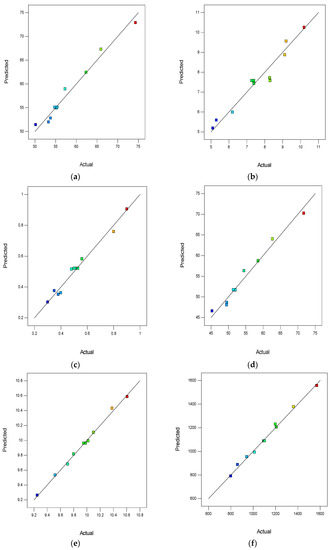
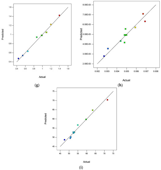
Figure 11.
Predicted versus actual plots for (a) CS, (b) weight loss, (c) change in length, (d) CS due to acid attack, (e) pH test, (f) RCPT, (g) weight gain, (h) expansion, (i) CS due to sulphate attack.
The impact of input variable interactions on outcomes is shown via 2D contour diagrams and 3D response surface charts. For the CS, length change, weight loss, pH test, CS due to acid attack, RCPT, expansion, weight gain, and CS due to sulphate attack mathematical models, the response surface plots for Figure 12, Figure 13, Figure 14, Figure 15, Figure 16, Figure 17, Figure 18, Figure 19 and Figure 20 are shown, correspondingly. In particular, the relationship between the parameters is depicted when there are two input variables, as there were in the current research. Demonstrated here are 2D contour diagrams and 3D response charts showing the relationship between PVA and multiwalled CNTs. The colour-coding of the diagrams shows the magnitude of the response as well as the numerous input component values taken into account. The 2D contour and 3D response charts for CS are shown in Figure 12a and Figure 12b, respectively. The figures demonstrate that the greatest concentration of CS was found at 0.05% multiwalled CNTs throughout all percentages of multiwalled CNTs and that using up to 0.05% multiwalled CNTs in the ECC combinations significantly increases the strength rating. This is because using multiwalled CNTs in an ECC mix has the aforementioned void-filling and densification impacts. Similar patterns may be seen in the other response surface plots for length change, weight loss, pH test, CS due to acid attack, RCPT, expansion, weight gain, and CS due to sulphate attack.
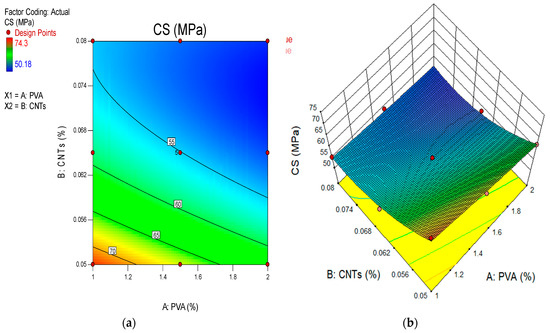
Figure 12.
(a) Two-dimensional contour diagram and (b) 3D response surface diagram for CS.
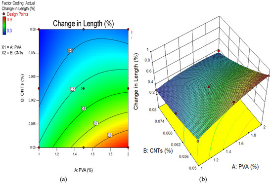
Figure 13.
(a) Two-dimensional contour diagram and (b) 3D response surface diagram for change in length.
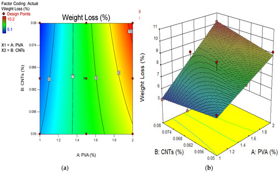
Figure 14.
(a) Two-dimensional contour diagram and (b) 3D response surface diagram for weight loss.
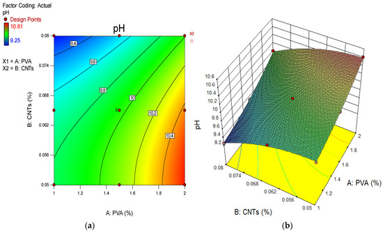
Figure 15.
(a) Two-dimensional contour diagram and (b) 3D response surface diagram for pH test.
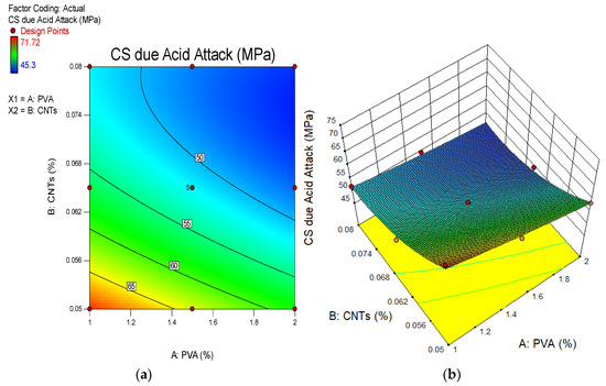
Figure 16.
(a) Two-dimensional contour diagram and (b) 3D response surface diagram for CS due to acid attack.
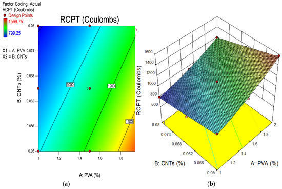
Figure 17.
(a) Two-dimensional contour diagram and (b) 3D response surface diagram for RCPT.
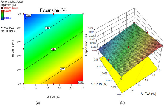
Figure 18.
(a) Two-dimensional contour diagram and (b) 3D response surface diagram for expansion.
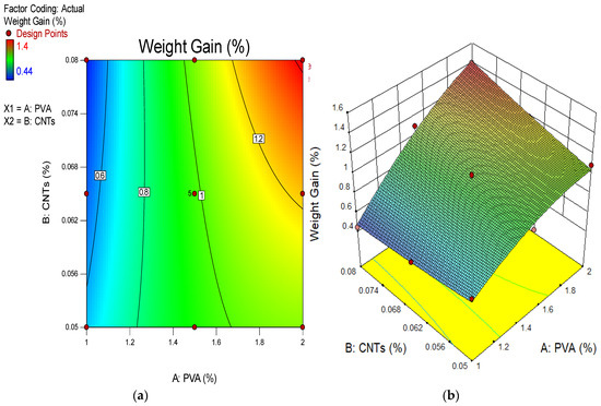
Figure 19.
(a) Two-dimensional contour diagram and (b) 3D response surface diagram for weight gain.
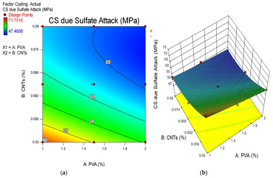
Figure 20.
(a) Two-dimensional contour diagram and (b) 3D response surface diagram for CS due to sulphate attack.
4.2. Optimization
Developing response algorithms and implementing RSM involve finding the right values for each variable to achieve the desired outcome. The model’s independent parameter is optimized and the desired function consists of goals for variables with their relative contributions. To get a desirable number between 0 and 1, a comparable approach was used [86,87,88,89,90]. As the desirability rating gets closer to one, the response function more frequently produces outstanding outcomes, and the optimum findings become more and more important in determining the dependent variable. The objectives for optimizing independent variables are shown in Table 7, while it is clear that the objectives for improving dependent variables differ. Though length change, weight loss, pH testing, RCPT, and weight growth were shown to result in decreased responses, optimization for CS, CS due to acid attack, expansion, and CS owing to sulphate attack were intended to boost responses. The optimization algorithm uses objective criteria to find the best solution, as shown in Figure 21. Maximum CS, length change, weight loss, pH test, CS due to acid attack, RCPT, expansion, weight gain, and CS due to sulphate attack were the results of the optimization process, and they were 72.88 MPa, 0.52%, 5.99%, 9.81, 70.24 MPa, 992.72 Coulombs, 0.0055%, 0.63%, and 70.35 MPa, respectively. Figure 22 shows a 77.10% desirability discrepancy between the mathematical model and response approach, indicating exceptionally useful results in the optimization process.

Table 7.
Optimization goals and results.
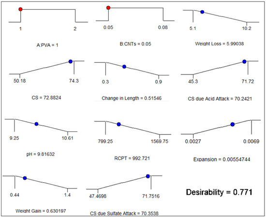
Figure 21.
Optimization solution ramp.
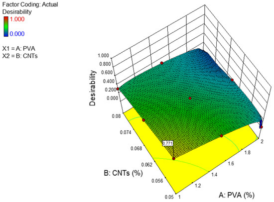
Figure 22.
Three-dimensional diagram of the desirability of the optimization.
5. Conclusions
The objective of this study was to find out the impact of multiwalled carbon nanotubes (CNTs) on the compressive strength and durability of ECC mixtures. From the investigation, the following findings were reached:
- The lowest strength of the ECC blended with several concentrations of PVA fibre was measured at 0.08% of multiwalled CNTs, while the maximum compressive strength was noticed at 0.05% of multiwalled CNTs. According to recommendations, the strongest ECC was produced by adding 0.05% multiwalled CNTs by weight of PC and, when more multiwalled CNTs were accumulated in the ECC, the strength began to decline over each curing time.
- The adverse effect response to a sulphate attack was due to the filling action of multiwalled CNTs that fill the empty spaces in pores and further impeded sulphate ion entry. Their diminishing efficiency might be attributed to nanomaterial agglomeration at high dosages.
- The ECC performed better because of the multiwalled CNTs in the combination when subjected to harsh circumstances. However, the composites that contained more multiwalled CNTs were considered to be more durable; mixtures that contained fewer multiwalled CNTs showed higher rates of weight loss and length change as a result of deterioration.
- The manufacturing of ECC uses more PVA fibres, which include varying amounts of multiwalled CNTs, raising pH levels, yet these pH levels were all shown to be less than those of the control combination. Additionally, when the amount of multiwalled CNTs as a nanomaterial grew in the combination, the pH value of the ECC mix mixed with different quantities of PVA fibre decreased.
- Utilizing carbon nanotubes resulted in an increased ability to resist penetration by chlorine ions. With the incorporation of multiwalled CNT ingredients, chloride permeability measurements decreased. Three mixtures, M4, M6, and M11, were categorized as having very low chloride penetration, while the remaining mixtures were categorized as having low chloride penetration.
- The compressive strength, sulphate resistance, and acid resistance were predicted using RSM models based on the quantities of PVA fibres and multiwalled CNTs used as nanoscale ingredients in the manufacturing of ECC. Every prototype had a level of certainty of 95%, while the difference between adjusted R2 and predicted R2 was not more than 0.2.
- The use of 0.05% multiwalled CNTs in an ECC combination with 1% to 1.50% of PVA fibre added can alleviate the challenges relating to large-scale implementation as well as the adverse effects of sulphate and acid attack, making it suitable for the construction sector.
- Multiwalled carbon nanotubes (MWCNTs) have shown remarkable potential in engineered cementitious composites (ECCs) and this has sparked a lot of attention in the area of materials research. The mechanical and functional qualities of the resultant composites may be improved by including MWCNTs in ECCs. Several desired properties can be obtained by spreading MWCNTs inside the cement matrix. MWCNTs are capable of strengthening the ECCs and enhancing their overall performance because of their remarkable mechanical qualities, which include great strength and stiffness. The MWCNTs’ tiny size and high aspect ratio also help them enhance the composites’ mechanical characteristics.
- To sum up, using MWCNTs in ECCs has the potential to significantly enhance the mechanical and environmental characteristics of these composites. The results thus far indicate that MWCNTs may help in the creation of high-performance and sustainable infrastructure materials, but further study is required.
Author Contributions
N.B.: Conceptualization, methodology, software, validation, investigation, data curation, writing—original draft preparation, writing—review and editing. B.S.M.: Conceptualization, supervision, funding acquisition, validation, formal analysis, writing—review and editing. M.S.L.: Conceptualization, methodology, supervision, funding acquisition. N.A.W.A.Z.: conceptualization, supervision, funding acquisition, validation. All authors have read and agreed to the published version of the manuscript.
Funding
The authors are thankful to Universiti Teknologi Petronas Malaysia for providing funding for performing this research work under the projects (015PBC-009 and 015LC0-391).
Data Availability Statement
Not applicable.
Conflicts of Interest
The authors declare no conflict of interest.
References
- An, C.; Duan, M.; Toledo Filho, R.D.; Estefen, S.F. Collapse of Sandwich Pipes with PVA Fiber Reinforced Cementitious Composites Core under External Pressure. Ocean Eng. 2014, 82, 1–13. [Google Scholar] [CrossRef]
- Sahmaran, M.; Li, M.; Li, V.C. Transport Properties of Engineered Cementitious Composites under Chloride Exposure. ACI Mater. J. 2007, 104, 604–611. [Google Scholar]
- Khed, V.C.; Mohammed, B.S.; Liew, M.S.; Abdullah Zawawi, N.A.W. Development of Response Surface Models for Self-Compacting Hybrid Fibre Reinforced Rubberized Cementitious Composite. Constr. Build. Mater. 2020, 232, 117191. [Google Scholar] [CrossRef]
- Mohammed, B.S.; Khed, V.C.; Liew, M.S. Optimization of Hybrid Fibres in Engineered Cementitious Composites. Constr. Build. Mater. 2018, 190, 24–37. [Google Scholar] [CrossRef]
- Zhang, Z.; Ma, H.; Qian, S. Investigation on Properties of ECC Incorporating Crumb Rubber of Different Sizes. J. Adv. Concr. Technol. 2015, 13, 241–251. [Google Scholar] [CrossRef]
- Singh, M.; Saini, B.; Chalak, H.D. Performance and Composition Analysis of Engineered Cementitious Composite (ECC)—A Review. J. Build. Eng. 2019, 26, 100851. [Google Scholar] [CrossRef]
- Wille, K.; Naaman, A.E.; El-Tawil, S.; Parra-Montesinos, G.J. Ultra-High Performance Concrete and Fiber Reinforced Concrete: Achieving Strength and Ductility without Heat Curing. Mater. Struct. Constr. 2012, 45, 309–324. [Google Scholar] [CrossRef]
- Li, V.C. Engineered Cementitious Composite (Ecc): Material, Structural, and Durability Performance. In Concrete Construction Engineering Handbook, 2nd ed.; CRC Press: Boca Raton, FL, USA, 2008; pp. 1001–1048. [Google Scholar]
- Zheng, Q.; Han, B.; Cui, X.; Yu, X.; Ou, J. Graphene-Engineered Cementitious Composites: Small Makes a Big Impact. Nanomater. Nanotechnol. 2017, 7. [Google Scholar] [CrossRef]
- Bassuoni, M.T.; Nehdi, M.L. Durability of Self-Consolidating Concrete to Sulfate Attack under Combined Cyclic Environments and Flexural Loading. Cem. Concr. Res. 2009, 39, 206–226. [Google Scholar] [CrossRef]
- Grengg, C.; Mittermayr, F.; Baldermann, A.; Böttcher, M.E.; Leis, A.; Koraimann, G.; Grunert, P.; Dietzel, M. Microbiologically Induced Concrete Corrosion: A Case Study from a Combined Sewer Network. Cem. Concr. Res. 2015, 77, 16–25. [Google Scholar] [CrossRef]
- Diab, A.M.; Elyamany, H.E.; Abd Elmoaty, A.E.M.; Shalan, A.H. Prediction of Concrete Compressive Strength Due to Long Term Sulfate Attack Using Neural Network. Alexandria Eng. J. 2014, 53, 627–642. [Google Scholar] [CrossRef]
- Arel, H.Ş.; Thomas, B.S. The Effects of Nano- and Micro-Particle Additives on the Durability and Mechanical Properties of Mortars Exposed to Internal and External Sulfate Attacks. Results Phys. 2017, 7, 843–851. [Google Scholar] [CrossRef]
- Mehta, P.K. Mechanism of Sulfate Attack on Portland Cement Concrete—Another Look. Cem. Concr. Res. 1983, 13, 401–406. [Google Scholar] [CrossRef]
- Tchamba, A.B.; Sofack, J.C.; Yongue, R.; Melo, U.C. Formulation of Calcium Dialuminate (CaO·2Al2O3) Refractory Cement from Local Bauxite. J. Asian Ceram. Soc. 2015, 3, 164–172. [Google Scholar] [CrossRef]
- Harrison, W.H. Durability of Concrete in Acidic Soils and Waters. Concrete 1987, 21, 18–24. [Google Scholar]
- Soutsos, M. Concrete Durability: A Practical Guide to the Design of Durable Concrete Structures; Institution of Civil Engineers: London, UK, 2009; p. 314. [Google Scholar]
- Gaze, M.E.; Crammond, N.J. Formation of Thaumasite in a Cement:Lime:Sand Mortar Exposed to Cold Magnesium and Potassium Sulfate Solutions. Cem. Concr. Compos. 2000, 22, 209–222. [Google Scholar] [CrossRef]
- Stanton, T.E. Expansion of Concrete through Reaction between Cement and Aggregate. Trans. Am. Soc. Civ. Eng. 1942, 107, 54–84. [Google Scholar] [CrossRef]
- Diab, A.M.; Elyamany, H.E.; Abd Elmoaty, A.E.M.; Sreh, M.M. Effect of Nanomaterials Additives on Performance of Concrete Resistance against Magnesium Sulfate and Acids. Constr. Build. Mater. 2019, 210, 210–231. [Google Scholar] [CrossRef]
- Diab, A.M.; Awad, A.E.M.; Elyamany, H.E.; Abd Elmoaty, A.E.M. Guidelines in Compressive Strength Assessment of Concrete Modified with Silica Fume Due to Magnesium Sulfate Attack. Constr. Build. Mater. 2012, 36, 311–318. [Google Scholar] [CrossRef]
- Yang, D.Y.; Luo, J.J. The Damage of Concrete under Flexural Loading and Salt Solution. Constr. Build. Mater. 2012, 36, 129–134. [Google Scholar] [CrossRef]
- Essawy, A.A.; Abd, S. Physico-Mechanical Properties, Potent Adsorptive and Photocatalytic Efficacies of Sulfate Resisting Cement Blends Containing Micro Silica and Nano-TiO2. Constr. Build. Mater. 2014, 52, 1–8. [Google Scholar] [CrossRef]
- Atahan, H.N.; Arslan, K.M. Improved Durability of Cement Mortars Exposed to External Sulfate Attack: The Role of Nano & Micro Additives. Sustain. Cities Soc. 2016, 22, 40–48. [Google Scholar] [CrossRef]
- Pavlík, V.; Unčík, S. The Rate of Corrosion of Hardened Cement Pastes and Mortars with Additive of Silica Fume in Acids. Cem. Concr. Res. 1997, 27, 1731–1745. [Google Scholar] [CrossRef]
- Mansouri Sarvandani, M.; Mahdikhani, M.; Aghabarati, H.; Haghparast Fatmehsari, M. Effect of Functionalized Multi-Walled Carbon Nanotubes on Mechanical Properties and Durability of Cement Mortars. J. Build. Eng. 2021, 41, 102407. [Google Scholar] [CrossRef]
- Konsta-Gdoutos, M.S.; Metaxa, Z.S.; Shah, S.P. Multi-Scale Mechanical and Fracture Characteristics and Early-Age Strain Capacity of High Performance Carbon Nanotube/Cement Nanocomposites. Cem. Concr. Compos. 2010, 32, 110–115. [Google Scholar] [CrossRef]
- Konsta-Gdoutos, M.S.; Metaxa, Z.S.; Shah, S.P. Highly Dispersed Carbon Nanotube Reinforced Cement Based Materials. Cem. Concr. Res. 2010, 40, 1052–1059. [Google Scholar] [CrossRef]
- Carriço, A.; Bogas, J.A.; Hawreen, A.; Guedes, M. Durability of Multi-Walled Carbon Nanotube Reinforced Concrete. Constr. Build. Mater. 2018, 164, 121–133. [Google Scholar] [CrossRef]
- Lee, H.S.; Balasubramanian, B.; Gopalakrishna, G.V.T.; Kwon, S.J.; Karthick, S.P.; Saraswathy, V. Durability Performance of CNT and Nanosilica Admixed Cement Mortar. Constr. Build. Mater. 2018, 159, 463–472. [Google Scholar] [CrossRef]
- Xu, S.; Liu, J.; Li, Q. Mechanical Properties and Microstructure of Multi-Walled Carbon Nanotube-Reinforced Cement Paste. Constr. Build. Mater. 2015, 76, 16–23. [Google Scholar] [CrossRef]
- Abu Al-Rub, R.K.; Ashour, A.I.; Tyson, B.M. On the Aspect Ratio Effect of Multi-Walled Carbon Nanotube Reinforcements on the Mechanical Properties of Cementitious Nanocomposites. Constr. Build. Mater. 2012, 35, 647–655. [Google Scholar] [CrossRef]
- Hu, Y.; Luo, D.; Li, P.; Li, Q.; Sun, G. Fracture Toughness Enhancement of Cement Paste with Multi-Walled Carbon Nanotubes. Constr. Build. Mater. 2014, 70, 332–338. [Google Scholar] [CrossRef]
- Kim, H.K.; Nam, I.W.; Lee, H.K. Enhanced Effect of Carbon Nanotube on Mechanical and Electrical Properties of Cement Composites by Incorporation of Silica Fume. Compos. Struct. 2014, 107, 60–69. [Google Scholar] [CrossRef]
- Kim, G.M.; Yang, B.J.; Cho, K.J.; Kim, E.M.; Lee, H.K. Influences of CNT Dispersion and Pore Characteristics on the Electrical Performance of Cementitious Composites. Compos. Struct. 2017, 164, 32–42. [Google Scholar] [CrossRef]
- Han, B.; Zhang, L.; Sun, S.; Yu, X.; Dong, X.; Wu, T.; Ou, J. Electrostatic Self-Assembled Carbon Nanotube/Nano Carbon Black Composite Fillers Reinforced Cement-Based Materials with Multifunctionality. Compos. Part A Appl. Sci. Manuf. 2015, 79, 103–115. [Google Scholar] [CrossRef]
- Torabian Isfahani, F.; Li, W.; Redaelli, E. Dispersion of Multi-Walled Carbon Nanotubes and Its Effects on the Properties of Cement Composites. Cem. Concr. Compos. 2016, 74, 154–163. [Google Scholar] [CrossRef]
- Musso, S.; Tulliani, J.M.; Ferro, G.; Tagliaferro, A. Influence of Carbon Nanotubes Structure on the Mechanical Behavior of Cement Composites. Compos. Sci. Technol. 2009, 69, 1985–1990. [Google Scholar] [CrossRef]
- Wang, B.; Han, Y.; Liu, S. Effect of Highly Dispersed Carbon Nanotubes on the Flexural Toughness of Cement-Based Composites. Constr. Build. Mater. 2013, 46, 8–12. [Google Scholar] [CrossRef]
- ASTM C150; Standard Specification for Portland Cement. ASTM International: West Conshohocken, PA, USA, 2015.
- ASTM C618-15; Standard Specification for Coal Fly Ash and Raw or Calcined Natural Pozzolan for Use in Concrete. ASTM International: West Conshohocken, PA, USA, 2015.
- Ma-Hock, L.; Treumann, S.; Strauss, V.; Brill, S.; Luizi, F.; Mertler, M.; Wiench, K.; Gamer, A.O.; van Ravenzwaay, B.; Landsiedel, R. Inhalation Toxicity of Multiwall Carbon Nanotubes in Rats Exposed for 3 Months. Toxicol. Sci. 2009, 112, 468–481. [Google Scholar] [CrossRef]
- Abdulhameed, A.; Halin, I.A.; Mohtar, M.N.; Hamidon, M.N. PH-Sensing Characteristics of Multi-Walled Carbon Nanotube Assembled across Transparent Electrodes with Dielectrophoresis. IEEE Sens. J. 2021, 21, 26594–26601. [Google Scholar] [CrossRef]
- Eatemadi, A.; Daraee, H.; Karimkhanloo, H.; Kouhi, M.; Zarghami, N.; Akbarzadeh, A.; Abasi, M.; Hanifehpour, Y.; Joo, S.W. Carbon Nanotubes: Properties, Synthesis, Purification, and Medical Applications. Nanoscale Res. Lett. 2014, 9, 393. [Google Scholar] [CrossRef]
- Zhang, Z.; Yuvaraj, A.; Di, J.; Qian, S. Matrix Design of Light Weight, High Strength, High Ductility ECC. Constr. Build. Mater. 2019, 210, 188–197. [Google Scholar] [CrossRef]
- Mohammed, B.S.; Achara, B.E.; Liew, M.S.; Alaloul, W.S.; Khed, V.C. Effects of Elevated Temperature on the Tensile Properties of NS-Modified Self-Consolidating Engineered Cementitious Composites and Property Optimization Using Response Surface Methodology (RSM). Constr. Build. Mater. 2019, 206, 449–469. [Google Scholar] [CrossRef]
- BS EN 12390-3; Testing Harden Concrete—Compressive Strength of Test Specimens. BSI: London, UK, 2009.
- AASHTO (T277-15); Electrical Indication of Concrete’s Ability to Resist Chloride Ion Penetration. American Association of State and Highway Transportation Officials: Washington, DC, USA, 2015.
- ASTM C1202-19; Standard Test Method for Electrical Indication of Concrete’s Ability to Resist Chloride Ion Penetration. ASTM: West Conshohocken, PA, USA, 2019.
- Praveenkumar, T.R.; Vijayalakshmi, M.M.; Meddah, M.S. Strengths and Durability Performances of Blended Cement Concrete with TiO2 Nanoparticles and Rice Husk Ash. Constr. Build. Mater. 2019, 217, 343–351. [Google Scholar] [CrossRef]
- Zhang, P.; Su, J.; Guo, J.; Hu, S. Influence of Carbon Nanotube on Properties of Concrete: A Review. Constr. Build. Mater. 2023, 369, 130388. [Google Scholar] [CrossRef]
- Lu, Z.; Hou, D.; Meng, L.; Sun, G.; Lu, C.; Li, Z. Mechanism of Cement Paste Reinforced by Graphene Oxide/Carbon Nanotubes Composites with Enhanced Mechanical Properties. RSC Adv. 2015, 5, 100598–100605. [Google Scholar] [CrossRef]
- Yang, H.; Monasterio, M.; Cui, H.; Han, N. Experimental Study of the Effects of Graphene Oxide on Microstructure and Properties of Cement Paste Composite. Compos. Part A Appl. Sci. Manuf. 2017, 102, 263–272. [Google Scholar] [CrossRef]
- Lv, S.; Ma, Y.; Qiu, C.; Sun, T.; Liu, J.; Zhou, Q. Effect of Graphene Oxide Nanosheets of Microstructure and Mechanical Properties of Cement Composites. Constr. Build. Mater. 2013, 49, 121–127. [Google Scholar] [CrossRef]
- Shamsaei, E.; de Souza, F.B.; Yao, X.; Benhelal, E.; Akbari, A.; Duan, W. Graphene-Based Nanosheets for Stronger and More Durable Concrete: A Review. Constr. Build. Mater. 2018, 183, 642–660. [Google Scholar] [CrossRef]
- Eftekhari, M.; Mohammadi, S. Multiscale Dynamic Fracture Behavior of the Carbon Nanotube Reinforced Concrete under Impact Loading. Int. J. Impact Eng. 2016, 87, 55–64. [Google Scholar] [CrossRef]
- Liew, K.M.; Kai, M.F.; Zhang, L.W. Carbon Nanotube Reinforced Cementitious Composites: An Overview. Compos. Part A Appl. Sci. Manuf. 2016, 91, 301–323. [Google Scholar] [CrossRef]
- Li, Y.; Li, H.; Wang, Z.; Jin, C. Effect and Mechanism Analysis of Functionalized Multi-Walled Carbon Nanotubes (MWCNTs) on C-S-H Gel. Cem. Concr. Res. 2020, 128, 105955. [Google Scholar] [CrossRef]
- Nam, I.W.; Park, S.M.; Lee, H.K.; Zheng, L. Mechanical Properties and Piezoresistive Sensing Capabilities of FRP Composites Incorporating CNT Fibers. Compos. Struct. 2017, 178, 1–8. [Google Scholar] [CrossRef]
- Yakovlev, G.; Keriené, J.; Gailius, A.; Girniené, I. Cement Based Foam Concrete Reinforced by Carbon Nanotubes. Mater. Sci. 2006, 12, 147–151. [Google Scholar]
- Ramyar, K.; Inan, G. Sodium Sulfate Attack on Plain and Blended Cements. Build. Environ. 2007, 42, 1368–1372. [Google Scholar] [CrossRef]
- Mohammed, B.S.; Yen, L.Y.; Haruna, S.; Seng Huat, M.L.; Abdulkadir, I.; Al-Fakih, A.; Liew, M.S.; Abdullah Zawawi, N.A.W. Effect of Elevated Temperature on the Compressive Strength and Durability Properties of Crumb Rubber Engineered Cementitious Composite. Materials 2020, 13, 3516. [Google Scholar] [CrossRef]
- Sabapathy, L.; Mohammed, B.S.; Al-Fakih, A.; Wahab, M.M.A.; Liew, M.S.; Amran, Y.H.M. Acid and Sulphate Attacks on a Rubberized Engineered Cementitious Composite Containing Graphene Oxide. Materials 2020, 13, 3125. [Google Scholar] [CrossRef] [PubMed]
- Gu, L.; Bennett, T.; Visintin, P. Sulphuric Acid Exposure of Conventional Concrete and Alkali-Activated Concrete: Assessment of Test Methodologies. Constr. Build. Mater. 2019, 197, 681–692. [Google Scholar] [CrossRef]
- Chintalapudi, K.; Pannem, R.M.R. Enhanced Chemical Resistance to Sulphuric Acid Attack by Reinforcing Graphene Oxide in Ordinary and Portland Pozzolana Cement Mortars. Case Stud. Constr. Mater. 2022, 17, e01452. [Google Scholar] [CrossRef]
- Arif, M.; Gupta, V.; Choudhary, H.; Kumar, S.; Basu, P. Performance Evaluation of Cement Concrete Containing Sandstone Slurry. Constr. Build. Mater. 2018, 184, 432–439. [Google Scholar] [CrossRef]
- Aiken, T.A.; Kwasny, J.; Sha, W.; Soutsos, M.N. Effect of Slag Content and Activator Dosage on the Resistance of Fly Ash Geopolymer Binders to Sulfuric Acid Attack. Cem. Concr. Res. 2018, 111, 23–40. [Google Scholar] [CrossRef]
- Wan, X.M.; Wittmann, F.H.; Zhao, T.J.; Fan, H. Chloride Content and PH Value in the Pore Solution of Concrete under Carbonation. J. Zhejiang Univ. Sci. A 2013, 14, 71–78. [Google Scholar] [CrossRef]
- Kumari, K.; Preetha, R.; Ramachandran, D.; Vishwakarma, V.; George, R.P.; Sundaramurthy, C.; Kamachi Mudali, U.; Sivathanu Pillai, C. Nanoparticles for Enhancing Mechanical Properties of Fly Ash Concrete. Mater. Today Proc. 2016, 3, 2387–2393. [Google Scholar] [CrossRef]
- Zeng, H.; Li, Y.; Zhang, J.; Chong, P.; Zhang, K. Effect of Limestone Powder and Fly Ash on the PH Evolution Coefficient of Concrete in a Sulfate-Freeze–Thaw Environment. J. Mater. Res. Technol. 2022, 16, 1889–1903. [Google Scholar] [CrossRef]
- Khotbehsara, M.M.; Miyandehi, B.M.; Naseri, F.; Ozbakkaloglu, T.; Jafari, F.; Mohseni, E. Effect of SnO2, ZrO2, and CaCO3 Nanoparticles on Water Transport and Durability Properties of Self-Compacting Mortar Containing Fly Ash: Experimental Observations and ANFIS Predictions. Constr. Build. Mater. 2018, 158, 823–834. [Google Scholar] [CrossRef]
- Schwarz, N.; Neithalath, N. Influence of a Fine Glass Powder on Cement Hydration: Comparison to Fly Ash and Modeling the Degree of Hydration. Cem. Concr. Res. 2008, 38, 429–436. [Google Scholar] [CrossRef]
- Miyandehi, B.M.; Feizbakhsh, A.; Yazdi, M.A.; Liu, Q.-f.; Yang, J.; Alipour, P. Performance and Properties of Mortar Mixed with Nano-CuO and Rice Husk Ash. Cem. Concr. Compos. 2016, 74, 225–235. [Google Scholar] [CrossRef]
- Chiranjiakumari Devi, S.; Ahmad Khan, R. Influence of Graphene Oxide on Sulfate Attack and Carbonation of Concrete Containing Recycled Concrete Aggregate. Constr. Build. Mater. 2020, 250, 118883. [Google Scholar] [CrossRef]
- Luhar, S.; Luhar, I.; Nicolaides, D.; Gupta, R. Durability Performance Evaluation of Rubberized Geopolymer Concrete. Sustainability 2021, 13, 5969. [Google Scholar] [CrossRef]
- Rodríguez, A.; Santamaría-Vicario, I.; Calderón, V.; Junco, C.; García-Cuadrado, J. Study of the Expansion of Cement Mortars Manufactured with Ladle Furnace Slag LFS. Mater. Constr. 2019, 69, e183. [Google Scholar] [CrossRef]
- Sarwary, M.H.; Yildirim, G.; Al-Dahawi, A.; Anil, Ö.; Khiavi, K.A.; Toklu, K.; Şahmaran, M. Self-Sensing of Flexural Damage in Large-Scale Steel-Reinforced Mortar Beams. ACI Mater. J. 2019, 116, 209–221. [Google Scholar] [CrossRef]
- Anwar, A.; Mohammed, B.S.; Wahab, M.A.; Liew, M.S. Enhanced Properties of Cementitious Composite Tailored with Graphene Oxide Nanomaterial—A Review. Dev. Built Environ. 2020, 1, 100002. [Google Scholar] [CrossRef]
- Tittelboom, K.V.; De Belie, N.; Hooton, D. A Critical Review on Test Methods for Evaluating the Resistance of Concrete against Sulfate Attack. In Performance of Cement-Based Materials in Aggressive Aqueous Environments; Rilem Publications: Bagneux, France, 2009; Volume 63, pp. 298–306. [Google Scholar]
- Hill, J.; Byars, E.A.; Sharp, J.H.; Lynsdale, C.J.; Cripps, J.C.; Zhou, Q. An Experimental Study of Combined Acid and Sulfate Attack of Concrete. Cem. Concr. Compos. 2003, 25, 997–1003. [Google Scholar] [CrossRef]
- Honglei, C.; Zuquan, J.; Penggang, W.; Jianhong, W.; Jian, L. Comprehensive Resistance of Fair-Faced Concrete Suffering from Sulfate Attack under Marine Environments. Constr. Build. Mater. 2021, 277, 122312. [Google Scholar] [CrossRef]
- Li, Y.; Yang, X.; Lou, P.; Wang, R.; Li, Y.; Si, Z. Sulfate Attack Resistance of Recycled Aggregate Concrete with NaOH-Solution-Treated Crumb Rubber. Constr. Build. Mater. 2021, 287, 123044. [Google Scholar] [CrossRef]
- Khan, M.H.; Zhu, H.; Sikandar, M.A.; Zamin, B.; Ahmad, M.; Sabri, M.M.S. Effects of Various Mineral Admixtures and Fibrillated Polypropylene Fibers on the Properties of Engineered Cementitious Composite (ECC) Based Mortars. Materials 2022, 15, 2880. [Google Scholar] [CrossRef]
- Behfarnia, K.; Farshadfar, O. The Effects of Pozzolanic Binders and Polypropylene Fibers on Durability of SCC to Magnesium Sulfate Attack. Constr. Build. Mater. 2013, 38, 64–71. [Google Scholar] [CrossRef]
- Alsanusi, S.; Bentaher, L. Prediction of Compressive Strength of Concrete from Early Age Test Result Using Design of Experiments (RSM). Int. J. Civ. Environ. Struct. Constr. Archit. Eng. 2015, 9, 1522–1526. [Google Scholar]
- Jayasinghe, A.; Orr, J.; Hawkins, W.; Ibell, T.; Boshoff, W.P. Comparing Different Strategies of Minimising Embodied Carbon in Concrete Floors. J. Clean. Prod. 2022, 345, 131177. [Google Scholar] [CrossRef]
- Shah, I.; Li, J.; Yang, S.; Zhang, Y.; Anwar, A. Experimental Investigation on the Mechanical Properties of Natural Fiber Reinforced Concrete. J. Renew. Mater. 2022, 10, 1307–1320. [Google Scholar] [CrossRef]
- Waqar, A.; Bheel, N.; Almujibah, H.R.; Benjeddou, O.; Alwetaishi, M.; Ahmad, M.; Sabri, M.M.S. Effect of Coir Fibre Ash (CFA) on the Strengths, Modulus of Elasticity and Embodied Carbon of Concrete Using Response Surface Methodology (RSM) and Optimization. Results Eng. 2023, 17, 100883. [Google Scholar] [CrossRef]
- Bheel, N.; Ali, M.O.A.; Shafiq, N.; Almujibah, H.R.; Awoyera, P.; Benjeddou, O.; Shittu, A.; Olalusi, O.B. Utilization of Millet Husk Ash as a Supplementary Cementitious Material in Eco-Friendly Concrete: RSM Modelling and Optimization. Structures 2023, 49, 826–841. [Google Scholar] [CrossRef]
- Bheel, N.; Benjeddou, O.; Almujibah, H.R.; Abbasi, S.A.; Sohu, S.; Ahmad, M.; Sabri Sabri, M.M. Effect of Calcined Clay and Marble Dust Powder as Cementitious Material on the Mechanical Properties and Embodied Carbon of High Strength Concrete by Using RSM-Based Modelling. Heliyon 2023, 9, e15029. [Google Scholar] [CrossRef] [PubMed]
Disclaimer/Publisher’s Note: The statements, opinions and data contained in all publications are solely those of the individual author(s) and contributor(s) and not of MDPI and/or the editor(s). MDPI and/or the editor(s) disclaim responsibility for any injury to people or property resulting from any ideas, methods, instructions or products referred to in the content. |
© 2023 by the authors. Licensee MDPI, Basel, Switzerland. This article is an open access article distributed under the terms and conditions of the Creative Commons Attribution (CC BY) license (https://creativecommons.org/licenses/by/4.0/).