Abstract
This research concerns the introduction and the structural analysis of masonry vaults in Puglia, a region in the south part of Italy, built between the sixteenth and the seventeen centuries. Such vaults have special shapes that make them unique in the overview of the masonry vaults spread all over the world. The present paper intends to shed light on the mechanical behavior of two typical vaults in Puglia, the “volta a spigoli” (edge vault) and the “volta a squadro” (square vault). There are many contributions that explore the mechanical behavior of the classical vaults, but to the authors’ knowledge, this is the first attempt investigating the “volta a squadro”. The paper describes the adopted research methods. First, a building survey is carried out with the integration of previous geometry acquisitions performed by local stakeholders. Then, the analysis is pursued by a non-linear approach that suitably inserts cracks where stress concentrations occur. Two meaningful load conditions are taken into account and numerically investigated. Under vertical loads, numerical results have inferred the surveyed cracks and concluded that the safety factor is much higher than one. On the other hand, under the maximum seismic load, the safety factor is estimated to be about 30%. This work is the very first investigation on the structural performance of a “volta a squadro”.
Keywords:
square vaults; edge vaults; step-by-step analysis; finite elements; survey; crack analysis 1. Introduction
Since the introduction of the most ancient arched masonry structures in Egypt and Mesopotamia, arches, vaults, and domes have spread around the world with various shapes and technologies, and they represent nowadays a huge part of the world’s cultural heritage. Different shapes and technologies were developed depending on the geographical regions. This was mainly related to the characteristics of the available local stone and to the independent development of the local skills influenced by the local characteristics and history.
Vaults, and in general curved masonry structures, were mainly used in the past as a structural solution for spanning wide openings. In Europe, they were mostly developed during the Roman Empire and improved in the Middle Ages and in the Renaissance. Aesthetics, technology, and brick texture were refined century after century, by a trial-and-error approach [1], thanks to the improvement of the skills of local masons; they could even follow original and proper paths that changed from one geographical region to another. For instance, very original vaults were developed in Puglia, a southern region of Italy, that are different from any other vaults in the world and that have not been investigated so far.
Vaults were mainly conceived to bear vertical loads. Due to their intrinsic longevity, they have also undergone seismic events that highlighted their poor performance against lateral loads. Furthermore, vaults are mostly present in premises that are today addressed to private and public purposes and thus require a careful investigation of their safety level both with respect to the usual vertical loads and with respect to the rarer seismic loads. For these reasons, there is a huge production of scientific analyses and studies to propose theoretical and computational methods, to numerically test case studies, to carry out experimental surveys, and to propose strengthening techniques. Focusing our attention to the last two decades, in [2,3], for instance, a historical Iranian brick masonry vault was numerically investigated by a non-linear two-step procedure involving a smeared crack model. In [4], collapsed Italian slender vaults with no backfill were analyzed and a simplified analytical model was proposed to simulate their collapse. In [5], the authors pay attention to the seismic effects on churches’ vaults by a parametric analysis that relates seismic behavior with geometry, tensile strength, and infill. The influence of the brick pattern on the seismic behavior of cross vaults is also investigated in [6].
In [7], the authors analyzed the developmental transition in the tile vault, while in [8], a new procedure for evaluation of the safety factor and the limit conditions of masonry arches subject to gravity is presented. The seismic vulnerability of masonry structures has been studied in [9] as regards cross vaults and in [10] concerning the case study of Vanvitelli’s Modulus in Murena Palace.
A methodology for the probabilistic assessment of masonry vaults’ bearing capacity, also considering hidden defects, has been presented in [11].
Experimental tests on vaults can be found in [12]. As alternative to the nonlinear approach, the thrust surface method, is capable of computing the structural safety by the application of the lower bound theorem. The equilibrium path cannot be determined but the procedure allows the computation of the final collapse load for vertical and horizontal actions. Examples of such a method are given in [13,14].
In [15], an innovative experimental campaign is carried out on full-scale, non-structural masonry barrel vaults in order to assess the lateral performances of a strengthening technique based on fiber-reinforced polymer.
All the papers dealing with the mechanical behavior of the vaults are focused on barrel vaults or cross vaults; in [16], a comparison among different methods to model barrel vaults was carried out, and in [17], a cross vault was analyzed, considering the effect of different brick patterns. The present paper intends to shed light on the mechanical behavior of two typical vaults in Puglia, the “volta a spigoli” (edge vault) and the “volta a squadro” (square vault). To the authors’ knowledge, this is the first attempt at such an investigation. Its main novelty is twofold: to investigate a vault with geometry that is new compared to the classical vaults investigated in the literature, and to propose a different non-linear approach aimed at crack identification.
The vaults under analysis are located in the Monastery of “Teresiani scalzi” in Lecce, a Baroque city in the south of Italy. The history of the monastery and its geometric description are provided in Section 1, while the focus on the geometry and on the crack framework of the vaults is carried out in Section 2. The incremental analysis under vertical and horizontal loads is performed in Section 3. Some conclusions close the paper, tracing some possible future lines of research.
2. Teresiani Scalzi’s Monastery: History and Survey
The monastery is located in Lecce (Apulia) and it occupies an entire block together with Santa Teresa’s church. The construction of the building took at least 27 years (1620–1647), due to disagreements with Domenicani, who damaged it in 1620 [18].
According to Paone [19], the architect who designed the Monastery and followed the construction was Giuseppe Zimbalo, who also signed some columns in the church [20].
After the religious order’s abolition in 1807, the monastery became barracks in 1813 and a high school in 1970, but currently it is abandoned [21].
The monastery is a two-story building; the ground floor and first floor plans are depicted in Figure 1 and Figure 2, respectively. In 2000, some diagnostic investigations revealed the presence of impregnable underground rooms.

Figure 1.
Ground floor of the monastery under investigation.
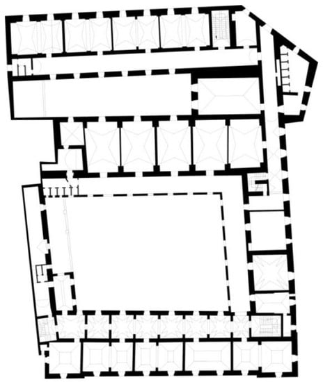
Figure 2.
First floor of the monastery under investigation.
As usual in a monastery, there is a main cloister around which there is an arcade. There is another smaller cloister surrounded by arcades and some of them were closed approximately in the XX century. The two floors are connected by four staircases.
There are two entrances to the building, one from Libertini street and the other from Basseo street.
The south and north facades (Figure 3 and Figure 4) are symmetric with respect to the centerline and they are characterized by a sequence of windows. The west facade (Figure 5) is plastered and less symmetric than the other ones.
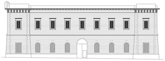
Figure 3.
North elevation of the monastery under investigation.
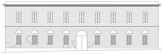
Figure 4.
South elevation of the monastery under investigation.
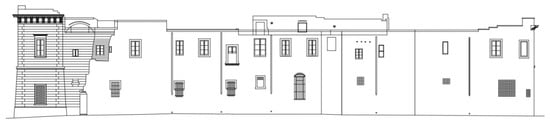
Figure 5.
West elevation of the monastery under investigation.
The building structure is composed of load-bearing walls and vaults. The masonry consists of stone blocks (local stone, called calcareous tufa) and lime mortar. The layout of blocks permits a better load distribution. There are many types of vaults: barrel vault, cross vault, hipped vault, keel vault, “volta a spigolo” (edge vault) and “volta a squadro” (square vault). The latter two vaults are typical local vaults that can be found only in this region [22].
3. Geometry and Crack Framework of the Vault
In Apulia, the use of vaults is widespread because of the shortage of wood. Even nowadays in Apulia there are skilled workers, called “voltaroli”, able to build vaults using the ancient technique [23]. The assembling procedure and, thus, the final brick texture, are very particular for this type of vault and they differ from the more common barrel and cross vaults. In this section, details on the constitutive parts of the vault are provided along with the procedure to acquire the exact geometry and to survey the crack framework.
3.1. Geometry of the Vault
Since the 16th century, the builders created two different types of vault shells: “a spigolo” (edge vault) (Figure 6) and “a squadro” (square vault) (Figure 7).
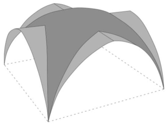
Figure 6.
Geometry of the edge vault.
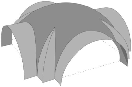
Figure 7.
Geometry of the square vault.
Both types consist of the “appese” (imposts), which represent the base of the vault resting on the columns, the “formate” (arches) and the “unghie” (groins or panel) representing, respectively, the arches mounted on the imposts and their protrusion toward the center of the room, and the “calotte”, the spherical dome closing the vault top (Figure 8 and Figure 9) [24].
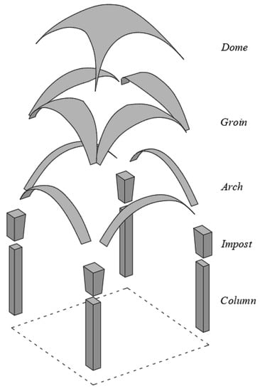
Figure 8.
Edge Vault. Exploded view.
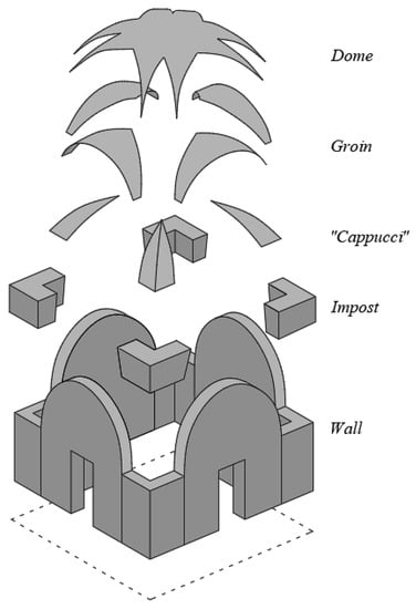
Figure 9.
Square vault. Exploded view.
The edge vault is commonly deemed to be an evolution of the cross vault [25]. The most important difference between those vaults is that the edge vault does not need a complete centering and it can be self-supporting at each stage of its partial completion. These features result from the progressive reduction of the four groins, which permits the vault to stand as a partial construction at each stage with a “cantilevered” profile [26].
The groins’ edges coincide with the bisector of the angle; they are called impost (“appese”) and they protrude, forming a ledge, called “dente” (Figure 10) [23].
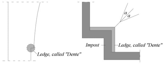
Figure 10.
Particulars of imposts and ledge, called “dente”.
This type of vault transfers the load to the corner pillars, as a cross vault.
In the edge, the load is transferred to the pillars, as a cross vault, through arches (“formate”) and impost (“appese”). The spherical dome (“calotta”) is a filling surface.
The square vault can be considered an evolution of the edge vault, in which the corner of the star is divided into two parts of a spherical surface. Each of them is a portion of a cloister vault and is called “cappuccio” (Figure 9) [26]. In the square vault, the angular imposts (“appese”) are larger.
In a square vault, the thrust is smaller than an edge vault, as the load is distributed on a larger surface and the load is transferred to a bigger surface, called “squadro”. Furthermore, the walls under the square vault are often slimmer than the pillars of an edge vault.
The geometrical data were extracted on the basis of both previous surveys carried out by local architects and a survey performed by one of the authors. All these survey campaigns allowed the extraction of the main geometrical data of the vault (most significant plan sizes, thickness of the vault, curvatures in some critical points, wall thickness), which are reported in Figure 11, and of the crack framework, paying attention to the cracks that turned out to be passing through the thickness during the authors’ survey.
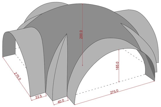
Figure 11.
Geometry of the surveyed vault.
The necessary thicknesses of the involved portion of walls and of the vault were surveyed by some drilling tests carried out during the authors’ survey.
3.2. Crack Inspection
As suggested by [27], geometry acquisition and crack investigation are essential to carry out the correct structural analysis.
The rooms of the monastery have not been accessible for a long time; therefore, the geometry was mainly acquired on the basis of a previous geometrical survey. Some of the drawings of this survey are depicted in Figure 1, Figure 2, Figure 3, Figure 4 and Figure 5. Despite the strict prohibition against entering the premises, one of the authors had a special authorization for one day to enter the room. During this visit, it was possible to check the most important measures reported in the previous survey and to inspect the crack framework.
In particular, the most notable cracks were the following:

Figure 12.
Crack on the keystone.
Figure 12.
Crack on the keystone.


Figure 13.
Crack on the vault.
Figure 13.
Crack on the vault.


Figure 14.
Crack along the wall.
Figure 14.
Crack along the wall.


Figure 15.
Crack on the angle of the vault.
Figure 15.
Crack on the angle of the vault.

It is worth emphasizing that the cracks reported here were assumed to be structural cracks because they revealed to be passing through the thickness, as observed during the survey campaign.
4. Non-Linear Incremental Analysis of the Vault
An incremental analysis [28] was carried out for a room, highlighted in green in Figure 16, covered with an edge vault and extrapolated from the rest of the building. The room is square-shaped; it is located on the first floor and it presents some cracking distributed throughout.
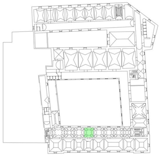
Figure 16.
First floor: room analyzed is highlighted in green.
The main geometrical difference between a cross vault and the square vault is the shape of its central part. In the square vault, it is a portion of the dome, whereas in the cross vault, it is the union of portions of two perpendicular cylinders. The survey described in Section 3.1 allowed us to locate exactly some points of the intrados of the square vault (see Figure 16 bis) under analysis. To generate the exact surface of the dome, in order to have the correct continuity with the groins, is a very complicated task that is still under investigation, as it requires a complete and detailed laser scanner survey. To overcome this issue, in the present approach, an equivalent cross vault has been built by minimizing the distance between the dome and groin in the points depicted in Figure 17.
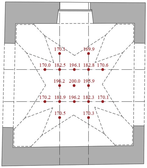
Figure 17.
Surveyed points of the square vaults.
The edge vault was approximated as a cross vault, as the attention was mainly focused on its internal arches. It is possible to state that each element of an edge vault works in the same way as a cross vault, with the exception of the spherical dome.
Furthermore, most of the cracks are distributed on groins, “appese”, and pillars.
Shell elements were used to discretize the middle plane of the vault. A parametric analysis was carried out to establish the coarsest mesh capable of providing reliable results with reference to the load condition described in Section 4.3, i.e., self-weight plus seismic action. The mesh was, in fact, refined up to the level at which the corresponding results were coincident with the results associated with the mesh of the previous level, with a maximum total square root error lower than 5%. No mesh dependency is reported, as the softening path does not occur, as the loading is a load control path.
In general, shell elements are a good approximation of a 3D solid structure if the thickness is reasonably lower than the other two directions. As already detailed in the previous sections, the geometrical characteristics of the vaults were obtained by both a survey performed by the authors and by the results of previous surveys carried out by local architects. In particular, a drilling test revealed that the thickness of the vault is a maximum of 20 cm (which is around 5% of the plan extension, which is 4 m). The vault is also a roof and therefore it is not loaded by backfill (usually necessary to provide a horizontal flat plane), which may influence the 2D structural behavior. Thickness/plan ratio and lack of backfill allowed the authors to assume the membrane behavior. The membrane assumption is also justified by the typical no-tension behavior of the brick–mortar assembly, which does not allow purely bending stress.
To the authors’ knowledge, no similar results are available in the literature due to the special features of the vault geometry under investigation, which is different from the classical available results. Despite this, a crack framework is available from the survey and, thus, the results of the present approach have been compared with the actual available ones.
4.1. Material Properties
Concerning the mechanical properties of the construction materials, it was not possible to carry out mechanical tests. Therefore, the values were extracted from the suggestions provided by the Italian Technical Norms (see Tab. C8.5.I in [29]) on the basis of the state of conservation and degradation of the materials, which was monitored during the inspection phase.
Since the main goal of the analysis is to investigate the behavior of the vault up to the collapse, the load combinations (the static with vertical load and the seismic with horizontal load) are not affected by amplification factors (as suggested by [29,30]). Furthermore, the normal yield (compressive and tensile) stresses were taken to be close to the characteristic value, i.e., without any reducing coefficient.
- -
- On the basis of the visual investigations and of the values suggested in the literature, the compression strength was set to 26 daN/cm2.
- -
- Analogously, the tensile strength was set to 2.6 daN/cm2, based on data from the literature, according to which the tensile strength of masonry is about 1/20 ÷ 1/10 of its compression strength.
Under tensile stress, the behavior is supposed to be elastic and perfectly brittle, i.e., crack opening occurs only in tension when the stress reaches the tensile strength.
4.2. Incremental Analysis under Vertical Loads
The vault under analysis was modeled by shell elements in the software Pro_Sap, also using the plug-in Pro_Sam, which is connected to the calculation engine SAM II [31]. The room is made of four walls, two arches, one door, and one window. Walls and arches are modelled as shell elements, and they are connected to the ground by hinges (Figure 18).
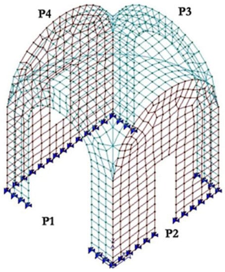
Figure 18.
Modeling of the room.
Three types of loads were considered:
- -
- vertical loads;
- -
- specific weight: 16 kN/m3;
- -
- live load: 1.0 kN/m2;
- -
- thrust of the vaults of adjacent rooms.
It is worth emphasizing that the specific weight is applied to each element of the mesh with the assumption that the thickness (see also Section 3) is 0.2 m. Due to the curvature of the vault, the weight is not applied uniformly on the horizontal projection, but its distribution is variable and computed automatically by the discretization process. The total weight of the vault is around 76.8 kN, which is equivalent to 4.8 kN/m2 of the horizontal projection. The same specific weight is applied to the vertical masonry piers, whose equivalent load is computed automatically and applied uniformly on each element, but due to their straight vertical shape, it is simply equivalent to a load per unit length of specific weight*B*s, where B and s are the length and the thickness, respectively, of the pier. The live load is computed in compliance with the Italian Technical Norm [29] with the knowledge that the vault is a roof, and therefore, assuming snow and maintenance actions, the former depends on the geographic area and is quantified at 0.5 kN/m2 in the location of the monastery, with the latter being a common maintenance load.
In order to compute the thrust due to the adjacent vaults, a single static analysis was carried out for each of the three adjacent vaults (see Figure 19). Each vault was loaded by its weight (16 kN/m3 on a thickness of 0.2 m for all the vaults) and its live loads (1 kN/m2 of horizontal projection for all the vaults). The computed thrust is reported in Table 1 and applied to the square vault under analysis (see Figure 20).
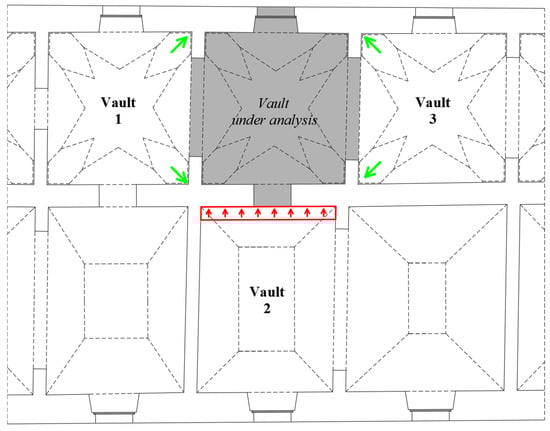
Figure 19.
Indication of the adjacent vaults that load their thrust on the vault under analysis; in green nodal forces (thrust of the square vault), in red a distributed load (thrust of pavilion vault).

Table 1.
Thrust computed for each adjacent vault.
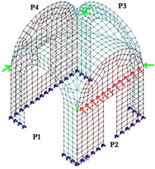
Figure 20.
Numerical thrust of the adjacent vaults of adjacent rooms: in green nodal forces (thrust of the square vault), in red a distributed load (thrust of pavilion vault).
In conclusion, a nodal force (10 kN in direction x and 10 kN in direction y, in green in Figure 20) was applied in each corner; furthermore, a distributed load (4.4 kN/m, in red in Figure 20) was imposed on the wall adjacent to vault 2 in Figure 19.
The non-linear analysis was carried out through the following steps:
- -
- increase the vertical loads until the tensile strength is reached in one node;
- -
- insert cracks or hinges where the maximum values of tensile stress have occurred; the crack is obtained by separating two adjacent shell elements.
4.2.1. Load Level 1
The initial load corresponds to the load multiplier equal to 1, that is, with the application of the loads as defined in the previous section. The behavior is still fully elastic.
The maximum value of tensile stress recorded in this load step is equal to 2.37 daN/cm2 (Figure 21), highlighted by a red circle in Figure 21, less than the tensile strength (2.6 daN/cm2).
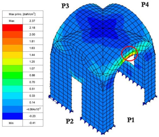
Figure 21.
Maximum values of tensile stress at Load Level 0. Vertical load.
Afterward, an iterative process is set up in order to establish the correct load multiplier associated with the occurrence of the maximum tensile stress in one element. Such an iterative process is carried out manually by suitably adapting the successive incremental steps.
The increase in load concerns only live load, as dead load can be considered fixed during the procedure.
The final multiplier of this step is 5.85 and the maximum value of the associated tensile stress, that is, 2.6 daN/cm2, is reached both on the arch section and as membrane stress at the intersection between the calotte and arch (see red circles in Figure 22 and in Figure 23).
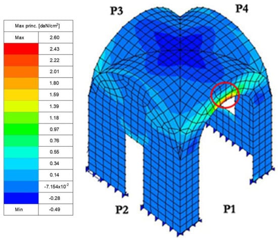
Figure 22.
Maximum values of tensile stress (membrane state) with α = 5.85. Vertical load.
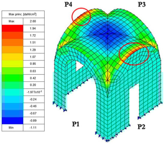
Figure 23.
Maximum values of tensile stress (banding behavior) with α = 5.85. Vertical load.
Therefore, a crack is initiated where the maximum value of tensile stress occurs (Figure 24).
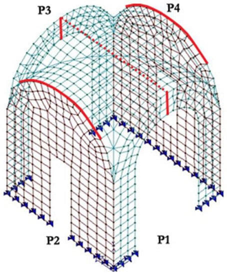
Figure 24.
Crack framework at Load Level 1. Vertical load.
The strategy by which to insert the crack can follow two different alternatives, depending on which stress state type reaches the failure.
- If the failure is related to the membrane state or it occurs along the intersection between the horizontal vault and the vertical arch, a part of shell can be eliminated in order to simulate the crack. Therefore, the mesh is refined and some small shell elements are eliminated (represented by a filled line in Figure 24).
- In the other cases (mainly when the failure is related to the banding behavior), the adjacent shell elements can be released in their relative rotation along the dotted line, represented in Figure 24.
It must be pointed out that the above procedure was set up in order to allow the correct redistribution of the stress with an increasing vertical load.
The procedure is repeated step by step by detaching one element per time where the maximum stress is reached. Due to the vertical load, the maximum stress propagates along the dotted line in Figure 24 up to the complete formation of what can be approximated as a theoretical hinge. A similar behavior occurs along the intersection line between the calotte and arch of walls P2 and P4 (see filled line in Figure 24)
4.2.2. Load Level 2
After the insertion of the cracks described in the previous paragraph, the structure is able to bear an increasing load, as the maximum tensile stress in the material is below the yield limit, i.e., there is a redistribution of stresses (Figure 25). The load can be again increased up to reaching the tensile strength in a different position (Figure 26), which occurs for a load multiplier α equal to 17.9.
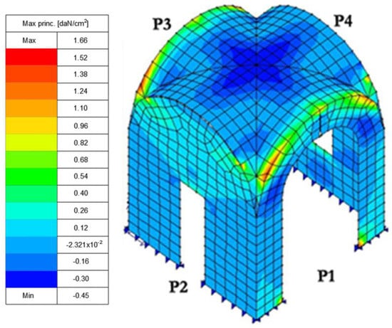
Figure 25.
Maximum values of tensile stress with α = 5.85, after insertion of cracks. Vertical load.
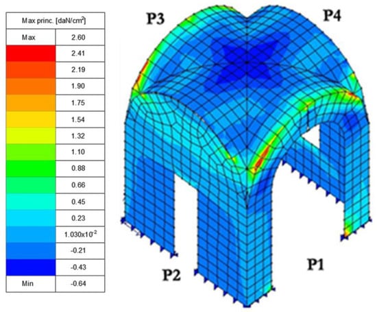
Figure 26.
Maximum values of tensile stress with α = 17.9. Vertical load.
The position of the new concentration of tensile stress (equaling the yield stress) is along the intersection line between the calotte and the arches of walls P1 and P3, where a crack was inserted. Even in this case, the procedure was repeated step by step by detaching one element per time where the maximum stress was reached. Due to the vertical load, the maximum stress propagates along the arches of walls P1 and P3 (Figure 27).
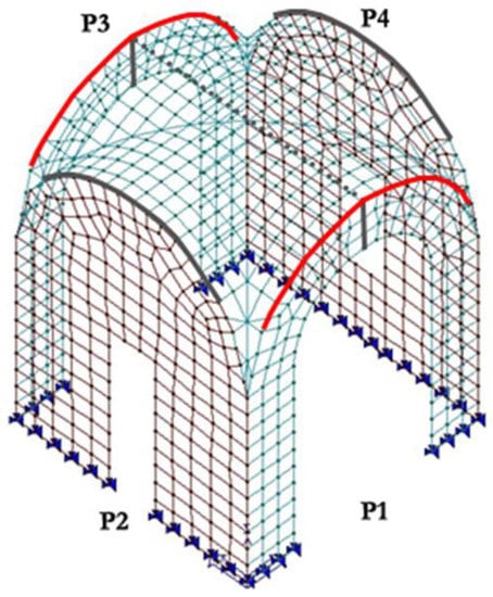
Figure 27.
New crack framework: crack of the load level 2 in red, crack of the load level 1 in grey. Vertical load.
In Figure 28 is depicted an intermediate step of the procedure of the insertion of the crack along the intersection line between the vault and walls P2 and P4.
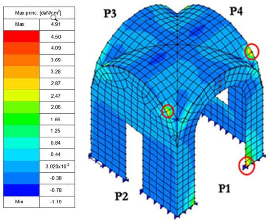
Figure 28.
Points (highlighted by red circles) with maximum value of tensile stress. Vertical load.
The tension principal stress in Figure 28, highlighted by red circles, exceeding the maximum tensile stress, without an increase in live load, is a consequence of the crack propagating along the line.
At the same time, the same behavior occurs at the base of the posts, so this support was removed. Also, in this case, the procedure was repeated step by step by detaching one element per time where the maximum stress was reached. Finally, the removed supports can be seen in Figure 29.
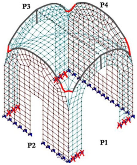
Figure 29.
New crack framework: red “x” localizes the removed supports. Vertical load.
Therefore, the crack on the lateral walls (P2, P4) propagated up to the surface of the vault, in order to follow the peak stress (Figure 29).
After that, a crack was inserted close to the imposts of the arch, highlighted by a red circle in Figure 30.
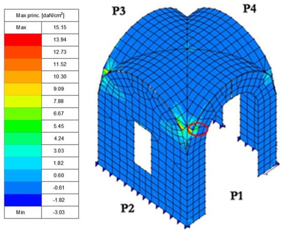
Figure 30.
Location, highlighted by a red circle, of the point of the maximum value of tensile stress. Vertical load.
The final crack framework is represented in Figure 31.
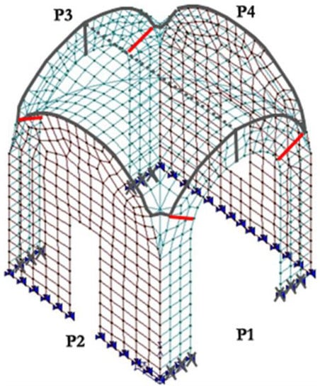
Figure 31.
Crack framework at Load Level 2: in red the last occurring cracks. Vertical load.
After inserting the cracks described above, the construction is recognized as the assembly of rigid blocks with a potential rigid body motion, i.e., the structure can collapse (Figure 32).
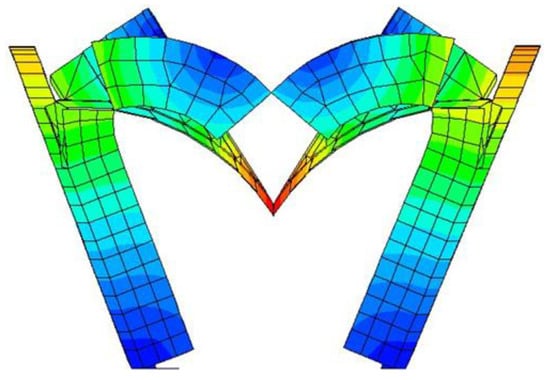
Figure 32.
Collapse mechanism occurring with vertical loads.
In fact, any load increment cannot be borne, and a rigid body mechanism occurs (Figure 32).
Therefore, the final collapse multiplier can be identified with the value reached at Load Level 2, that is, α_0 = 17.9.
To summarize, the mechanism is characterized by the following steps:
- cracks on keystones;
- propagation of this crack on the vault;
- cracks along the four arches;
- propagation of these cracks on the surface of the vault;
- removal of supports at the base of posts in order to allow the rigid rotation;
- cracks close to the arch imposts;
- formation of a rigid body mechanism.
The actual crack framework as surveyed on site is compared to the results obtained by the present procedure in Figure 33. On the left, the cracks obtained by the present procedures are highlighted in two different colors: in red, the crack obtained by the present procedure under the application of the actual loads, in magenta, the cracks that are estimated numerically to occur with increasing load. As depicted in the figure, the actual surveyed crack framework (right) is in good agreement with the numerical red crack distribution (left). Of course, the cracks highlighted in magenta on the left may be expected in case the vertical load is increased.
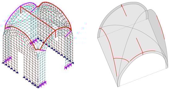
Figure 33.
Comparison between numerical (present approach, vertical load) crack framework (left) and the actual one (right).
4.3. Incremental Analysis under Horizontal Loads
Walls and vaults were modeled by shell elements, connected to the ground by hinges. The boundary of the vault is made up of four walls, two arches, a door, and a window (Figure 16).
Loads were introduced as follows:
- vertical loads;specific weight: 16 kN/m3 (applied following the same approach detailed in Section 4.2);live load: 1.0 kN/m2.
- Thrust of the vaults of adjacent rooms. As in the previous analysis, a nodal force (10 kN in direction x and 10 kN in direction y, in green in Figure 34), equivalent to the thrust of a cross vault, has been applied in each corner, and a distributed load (4.4 kN/m, in red in Figure 34), equivalent to the thrust of a hipped vault, has been imposed on the wall with the door.
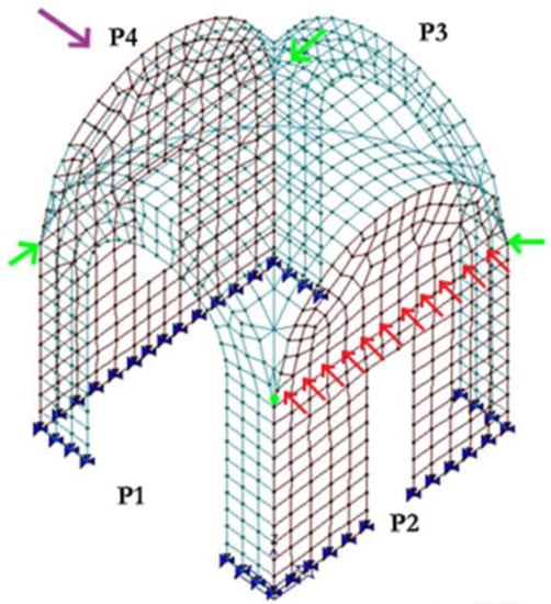 Figure 34. Actions applied on the vault under analysis: in green nodal forces (thrust of the square vault), in red a distributed load (thrust of pavilion vault), in purple the static load equivalent to earthquake.
 - Horizontal static load equivalent to earthquake in the weakest direction (less stiffness) with an intensity appropriate to the geographical location and provided by the following relation [29]:where Fh depends mainly on the response spectrum of the geographical area and is provided in § 3.2.3.5 of [29] on the basis of nominal life Vn, importance factor Cu, and knowledge level LC:
- LC 1 (low knowledge level), which corresponds to a Confidence Factor equal to 1.35;
- Cu = 1.5;
- Vn = 50 years;
- Locality: Lecce.
The acceleration (agS for SLV) corresponding to these values is equal to 0.1 g.
Also, the natural period corresponding to the maximum response of the spectrum has been considered.
It must be underlined that it is a common and reliable approach to deal with masonry by a static approach. The dynamic approach is more common for reinforced concrete and steel structures where the structural behavior can be correctly described by an assemblage of frame typologies. In fact, the equations dealing with the dynamic approach suppose a monolithic behavior that cannot be assumed in masonry structures, where the different part often behave as “almost independent” rigid bodies. The assumption that the static approach is possible only when the first mode is dominant cannot be applied to masonry. In fact, the Italian Technical Norm [29] and also the Eurocode allow the static approach, possibly enriched by non-linear material behavior. Two typical load distributions are allowed; one is a linear distribution, as provided by Equation (1), and the other is a constant distribution along the height.
After the software’s first analysis, it is possible to compare the stress map of seismic load (Figure 35) to that of the vertical load (Figure 36).
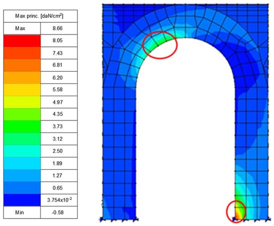
Figure 35.
Maximum values of tensile stress: seismic load. Vertical + seismic load.
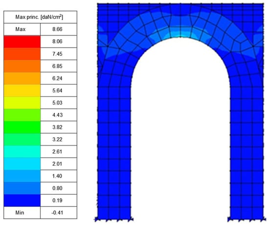
Figure 36.
Maximum values of tensile stress: vertical load.
First, values of tensile stress in Figure 35 are lower than those in Figure 36. Furthermore, the stress concentrations, as expected, are located in different places:
- With vertical loads, the maximum tensile stress is in the keystone.
- With seismic loads, the maximum tensile stress occurs, of course, at the bottom of both piers, as the earthquake acts in both directions.
Moreover, contrary to what happens with vertical loads, with seismic loads, the tensile strength is immediately reached. So, the load multiplier α is lower than 1.
As in the previous paragraph, the stress map was analyzed in order to define the correct mechanism.
Figure 35 shows that there is a maximum tensile stress in the lower right edge, so that support has been removed. Also, in this case, the procedure is repeated step by step by detaching one element per time where the maximum stress is reached. Finally, the supports’ removal led to the formation of an external hinge (Figure 37).
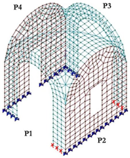
Figure 37.
Location (red “x”) of the removed supports at the base. Vertical + seismic load.
The new stress map is represented in Figure 38, and it shows the need to insert a crack on the arch (see red circle in Figure 38) in order to create a hinge on the intrados of the arch (Figure 39).
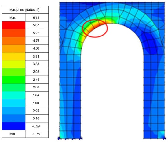
Figure 38.
Location, highlighted by a red circle, of the maximum values of tensile stress (walls P1 and P3). Vertical + seismic load.
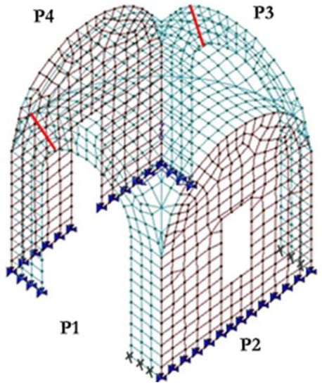
Figure 39.
Crack framework: the occurring cracks in red, grey “x” the removed supports of Figure 37. Vertical + seismic load.
The new stress map is represented in Figure 40, which shows high values of tensile stress along the intersection line between the calotte and arch of walls P2 and P4, so a crack was inserted (Figure 41).
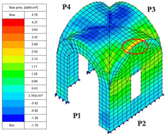
Figure 40.
Maximum values of stress due to bending moment. Vertical + seismic load.
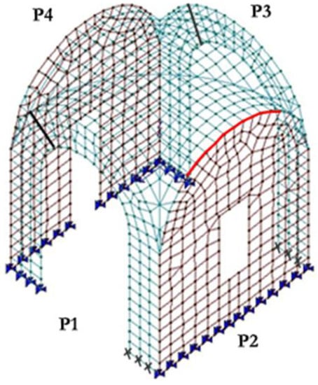
Figure 41.
Crack framework: in red the crack along the arch P2. Vertical + seismic load.
The stress map (Figure 42) shows that the maximum value of tensile stress occurs on the extrados of the arch of walls P1 and P3, highlighted by a red circle. For this reason, a crack was inserted; the procedure was repeated step by step by detaching one element per time where the maximum stress occurs. Finally, a hinge on the intrados of the arch was created and the crack propagates on the vault (in the corner), as Figure 43 shows.
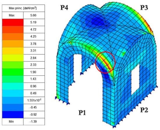
Figure 42.
Location of the maximum values of tensile stress (extrados of the arch of walls P1 and P3). Vertical + seismic load.
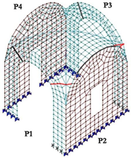
Figure 43.
Crack framework: in red the crack in the corner. Vertical + seismic load.
Figure 44 shows in green the compression isostatics and in red the traction isostatics; high values of tensile stress are recorded along the intersection line between the calotte and arch of walls P1 and P3. For this reason, a crack was inserted along the extrados of the arch, detaching one element per time where the maximum stress was reached; see Figure 45.
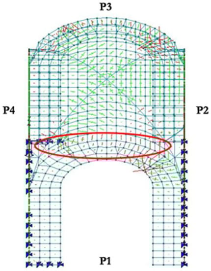
Figure 44.
Lines of tensile (red): maximum values along the intersection line between the calotte and arch (in the red circle). Vertical + seismic load.
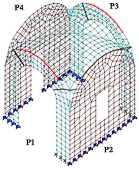
Figure 45.
Crack framework: in red the cracks along the arches P1 and P3. Vertical + seismic load.
Figure 46 shows high values of tensile stress at the bottom of wall P4, highlighted by red circles, so these supports were removed one at a time where the maximum stress was reached. Finally, the supports removed can be seen in Figure 47.
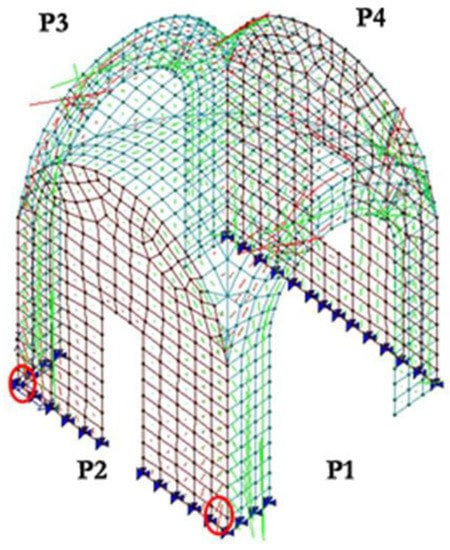
Figure 46.
Lines of tensile (red): maximum values at the bottom (red circle). Vertical + seismic load.
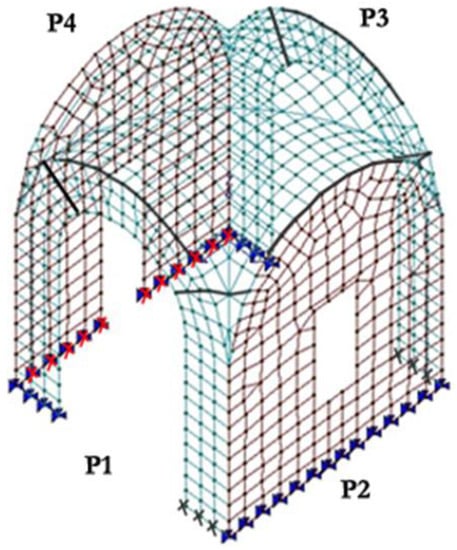
Figure 47.
Crack framework: red “x” locate the removed supports. Vertical + seismic load.
Figure 48 shows high values of tensile stress along the diagonal arches of the vault. For this reason, cracks were inserted perpendicular to the diagonal arches (Figure 49).
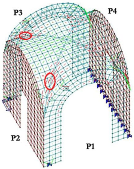
Figure 48.
Lines of tensile (red): maximum values along diagonal arches of the vault (red circles). Vertical + seismic load.
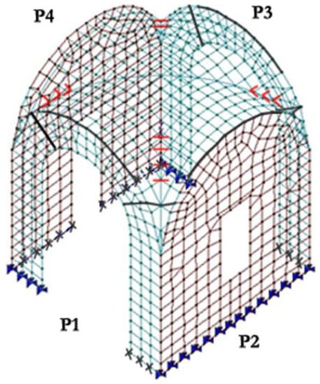
Figure 49.
Final crack framework. Vertical + seismic load.
The insertion of the cracks described above divides the entire construction into rigid blocks that are allowed to have a rigid body motion, i.e., the structure can collapse (Figure 50).
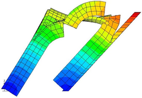
Figure 50.
Collapse mechanism occurring with vertical + seismic load.
5. Conclusions
Two masonry vaults that are typical in the Italian region of Apulia have been investigated in the present paper. Such vaults have geometrical features that are different from other types of vaults built in Europe. The geometrical characteristics have been detailed and differences with other vaults have been underlined. A square vault of the monastery of “Teresiani Scalzi” has been analyzed under vertical and seismic loads. On-site survey has shown the presence of some cracks in the vaults. A step-by-step non-linear finite element structural analysis has been carried out in order to locate stress concentrations that have caused the crack occurrences. Under vertical loads, the analysis has inferred the surveyed cracks and concluded that the safety factor is much higher than one. On the other hand, the safety factor computed by the analysis under the maximum seismic load, estimated by the Italian technical norms in the region of Apulia, is lower and estimated to be about 30%.
Finally, it is possible to assert that, through a quite simple non-linear finite element structural analysis, a vault with a complex geometry has been investigated and its crack framework has been inferred.
A few recommendations can be asserted for future work: to develop a 3D (solid) non-linear model in order to compare the present results with a 3D approach; to investigate possible differential settlements (by more detailed geometrical survey and non-destructive soil testing) that may have influenced the crack framework. As a matter of fact, the 3D models turn out to be numerically much more time-consuming and suffer from a possible lack of stability.
Author Contributions
Conceptualization, M.D.F.; methodology, V.M. and M.D.F.; software, M.D.F.; validation, V.M. and M.D.F.; formal analysis, M.D.F.; investigation, V.M. and M.D.F.; data curation, M.D.F.; writing—original draft preparation, V.M. and M.D.F.; writing—review and editing, V.M.; visualization, V.M. and M.D.F.; supervision, V.M.; funding acquisition, V.M. All authors have read and agreed to the published version of the manuscript.
Funding
This research received no external funding.
Data Availability Statement
Data are available from the authors on request.
Conflicts of Interest
The authors declare no conflict of interest.
References
- Gaetani, A.; Monti, G. Design and analysis of cross vaults along history. Int. J. Archit. Herit. 2016, 10, 841–856. [Google Scholar] [CrossRef]
- Mahini, S.S. Smeared crack material modelling for the nonlinear analysis of CFRP-strengthened historical brick vaults with adobe piers. Constr. Build. Mater. 2015, 74, 201–218. [Google Scholar] [CrossRef]
- Milani, G.; Lourenço, P.B. Simple homogenized model for the nonlinear analysis of FRP-strengthened masonry structures: Structural applications. J. Eng. Mech. 2013, 139, 77–93. [Google Scholar] [CrossRef]
- Ramaglia, G.; Lignola, G.P.; Prota, A. Collapse analysis of slender masonry barrel vaults. Eng. Struct. 2016, 117, 86–100. [Google Scholar] [CrossRef]
- Gaetani, G.; Lourenço, P.B.; Monti, G.; Milani, G. A parametric investigation on the seismic capacity of masonry cross vaults. Eng. Struct. 2017, 148, 686–703. [Google Scholar] [CrossRef]
- Alforno, M.; Venuti, F.; Monaco, A.; Calderini, C. Seismic behaviour of cross vaults with different brick pattern. Bull. Earthq. Eng. 2022, 20, 3921–3939. [Google Scholar] [CrossRef]
- Alcindor, M.; Jackson, D. Transmitting Culture through Building System: The Case of the Tile Vault. Buildings 2023, 13, 873. [Google Scholar] [CrossRef]
- Brandonisio, G.; De Angelis, F.; De Luca, A. Safety Factor of Masonry Arches under Gravity Loads. Buildings 2022, 12, 2059. [Google Scholar] [CrossRef]
- Vintzileou, E.; Mouzakis, C.; Karapitta, L.; Miltiadou-Fezans, A. Shake-table Testing of a Cross Vault. Buildings 2022, 12, 1984. [Google Scholar] [CrossRef]
- Gusella, V.; Liberotti, R. Seismic Vulnerability of Sub-Structures: Vantitelli’s Modulus in Murena Palace. Buildings 2020, 10, 164. [Google Scholar] [CrossRef]
- Zanaz, A.; Yotte, S.; Fouchal, F.; Chateauneuf, A. Efficient masonry vault inspection by Monte Carlo simulations: Case of hidden defect. Case Stud. Struct. Eng. 2016, 5, 1–12. [Google Scholar] [CrossRef]
- Rossi, M.; Calderini, C.; Lagomarsino, S. Experimental testing of the seismic in plane displacement capacity of masonry cross vaults through a scale model. Bull. Earthq. Eng. 2016, 14, 261–281. [Google Scholar] [CrossRef]
- Block, P.; Lachauer, L. Three-dimensional funicular analysis of masonry vaults. Mech. Res. Commun. 2014, 56, 53–60. [Google Scholar] [CrossRef]
- Fraddosio, A.; Lepore, N.; Piccioni, M.D. Thrust surface method: An innovative approach for the three-dimensional lower bound Limit Analysis of masonry vaults. Eng. Struct. 2020, 202, 109846. [Google Scholar] [CrossRef]
- Gattesco, N.; Boem, I.; Andretta, V. Experimental behaviour of non-structural masonry vaults reinforced through fibre-reinforced mortar coating and subjected to cyclic horizontal loads. Eng. Struct. 2018, 172, 419–431. [Google Scholar] [CrossRef]
- Coisson, E.; Ferretti, D.; Pagliari, F. A comparison between traditional and modern approaches for the structural modelling of brick masonry barrel vaults. In Proceedings of the 12th International Conference on Structural Analysis of Historical Constructions, SAHC 2020, Barcelona, Spain, 29 September–1 October 2021. [Google Scholar]
- Bianchini, N.; Mendes, N.; Lourenço, P.B.; Calderini, C.; Rossi, M. Seismic assessment of masonry cross vaults through numerical nonlinear static and dynamic analysis. In Proceedings of the 7th ECCOMAS Thematic Conference on Computational Methods in Structural Dynamics and Earthquake Engineering, Crete, Greece, 24–26 June 2019. [Google Scholar]
- Panettera, A. Notizie della città di Lecce (1610–1650). In App.ce a Rivista Storica Salentina; Palumbo, P., Ed.; Congedo Publisher: Lecce, Italy, 1904; Volume II. [Google Scholar]
- Paone, M. Studi Salentini; Centro di Studi Salentini: Lecce, Italy, 1961; Volume XII, pp. 404–405. [Google Scholar]
- Vacca, N. In rovina un capolavoro del bel barocco leccese. La Gazzetta del Mezzogiorno, 5 December 1904. [Google Scholar]
- Paone, M. I Teresiani in Lecce. In Archivio Storico Pugliese; Società di Storia Patria per la Puglia: Bari, Italy, 1965; Volume XVIII, pp. 209–215. [Google Scholar]
- Conte, C.; Aiello, M.A.; Ranieri, C.; Fabbrocino, G. Experimental and numerical modal analysis of masonry curved structures: Lecce’s edge vaults. In Proceedings of the XIV Conference ANIDIS—Associazione Nazionale Italiana di Ingegneria Sismica, Bari, Italy, 18–22 September 2011. [Google Scholar]
- Colaianni, V.G. Le Volte Leccesi. Internal Report—Institute of Architecture and Urban Planning of the Faculty of Engineering; University of Bari, Dedalo Libri Publisher: Turin, Italy, 1967. [Google Scholar]
- Pelliccio, A.; Saccucci, M. Interpreting Lecce Vaults with Analytical-Geometrical Models. Nexus Netw. J. 2020, 22, 915–935. [Google Scholar] [CrossRef]
- Pelliccio, A.; Saccucci, M.; Grande, E. A key nexus for vault system from Lecce: Stereometric correlation between shape and structure. In Nexus 2018 Architecture and Mathematics Conference Book; Kim Williams Book: Turin, Italy, 2018; pp. 209–215. [Google Scholar]
- Fallacara, G. The Lecce Vault: History, Construction Techniques, and New Design Perspectives. Nuts Bolts Constr. Hist. 2012, 3, 99–105. [Google Scholar]
- Direttiva del Presidente del Consiglio dei Ministri del 9 Febbraio, Supplemento Ordinario n. 54 alla G.U. n. 47 del 26 Febbraio 2011. Valutazione e Riduzione del Rischio Sismico del Patrimonio Culturale [In Italian]. Available online: https://www.gazzettaufficiale.it/eli/id/2011/02/26/11A02374/sg (accessed on 18 June 2023).
- Mallardo, V.; Malvezzi, R.; Milani, E.; Milani, G. Seismic vulnerability of historical masonry buildings: A case study in Ferrara. Eng. Struct. 2008, 30, 2223–2241. [Google Scholar] [CrossRef]
- NTC 2018, Decreto Ministeriale 17 Gennaio 2018, Norme Tecniche per le Costruzioni [In Italian], Ministry of Infrastructures and Transportations. 2018. Available online: https://www.gazzettaufficiale.it/eli/id/2018/02/20/18A00716/sg (accessed on 18 June 2023).
- Circolare 21 Gennaio 2019, n. 7 C.S.LL.PP. Istruzioni per l’applicazione dell’«Aggiornamento delle “Norme Tecniche per le Costruzioni”» di cui al Decreto Ministeriale 17 Gennaio 2018 [In Italian], Ministry of Infrastructures and Transportations. 2019. Available online: https://www.gazzettaufficiale.it/eli/id/2019/02/11/19A00855/sg (accessed on 18 June 2023).
- PROfessional Structural Analysis Program_PRO_Sap, User’s Guide. April 2019. Available online: https://www.2si.it/it/download-manuali-ed-esempi/ (accessed on 18 June 2023).


Disclaimer/Publisher’s Note: The statements, opinions and data contained in all publications are solely those of the individual author(s) and contributor(s) and not of MDPI and/or the editor(s). MDPI and/or the editor(s) disclaim responsibility for any injury to people or property resulting from any ideas, methods, instructions or products referred to in the content. |
© 2023 by the authors. Licensee MDPI, Basel, Switzerland. This article is an open access article distributed under the terms and conditions of the Creative Commons Attribution (CC BY) license (https://creativecommons.org/licenses/by/4.0/).