Article

Structural and Environmental Safety Studies of the Holy Mosque Area Using CFD

1
College of Engineering, Imam Mohammad Ibn Saud Islamic University (IMSIU), Riyadh 11432, Saudi Arabia
2
Faculty of Engineering, Ain Shams University, Cairo 11517, Egypt
Buildings 2023, 13(7), 1809; https://doi.org/10.3390/buildings13071809
Submission received: 31 May 2023 / Revised: 28 June 2023 / Accepted: 13 July 2023 / Published: 16 July 2023
(This article belongs to the Section Architectural Design, Urban Science, and Real Estate)

Abstract

:
A three-dimensional (3D) CFD model was developed, covering a square area of 3.64 km2 and comprising the Holy Mosque near its center, the actual terrain, and the main surrounding buildings. The gust wind effects on the existing cranes and the collapsed tower crane in 2015, the comfort of the pedestrians, and the air quality were studied for the first time in this area. The air quality was related to calm speed, accelerating the spreading of infectious diseases. The wind comfort levels were achieved in all selected locations. The wind speeds are generally low in the area. However, gusting wind currents appeared from limited directions, causing increments in wind speeds up to 30% and causing the tower crane to collapse. Therefore, finalizing work on some cranes is recommended soon, lowering the crane boom and stopping working on windy days or changing their places. The air quality in some sites may be relatively poor, such as at the lower terraces level. New tall buildings surrounding the mosque from the north and the east are not recommended unless studying their impacts on the air quality. Pruning north and east mounts can remarkably improve natural ventilation. Large-scale fans are another solution after a detailed simulation study.

1. Introduction

The studied area is the holiest place for all Muslims worldwide, with at least a million daily visits for praying. While in seasons such as Hajj and Ramadan, millions visit the Mosque daily, which may be considered the most crowded area in the world, especially during the seasons. Millions of Muslims worldwide visit the Holy Mosque with different cultures, languages, and health. Saudi authorities are keen to increase the capacity to achieve 15 million external visitors to the holy areas annually, because of the regularly expanding number of Muslims who want to perform Hajj, Omera, and pray in the Holy Mosque. Saudi Authorities have made massive efforts to achieve that by extending the Holy Mosque size, building new buildings to accommodate visitors, and developing the infrastructure. Some new tall structures surrounding the Holy Mosque have been constructed to serve visitors in the last few years. That affects the wind envelope, which has structural and environmental impacts on the buildings and people.
Three primary wind effects must be considered [1]: wind loads on structural, environmental studies, and wind loads for the façade. This research discussed the structural and environmental impact and excluded the wind loads for the façade.
The structural effects of the wind include:
  • The wind forces and moments on the building [2,3,4,5]
  • The vibration of the structures is one of the most significant effects of wind, especially on bridges and tall buildings [6]. It could lead to substantial displacements, accelerations, and resulting forces [7,8,9].
Many cranes are now working inside the studied area. One of the objectives of the current study is to check the wind velocity acting on the working cranes from all wind directions and compare the results with those in the cranes working in open space. The safety of these cranes is required to ensure the safety of the visitors/prayers to avoid such a catastrophic accident that occurred on 11 September 2015, 27th Thul-Qida 1436. One hundred and seven people died, and at least 238 were injured after the collapse of a tower crane at the Holy Mosque piazza during rest hours due to a strong wind. The tower crane was on the east side of the Holy Mosque beside the Royal Palace on Abu Kubais Mount. The long boom turned in the opposite direction, and the tower crane collapsed on the Masa’a.
On the other hand, away from the wind effects on the working structures, some environmental wind issues in cities can be tackled, such as
  • Accumulating vehicular emissions at the street level [10] affects air quality;
  • Degradation of outdoor thermal comfort [11,12,13,14];
  • The pedestrian-level wind was tackled in the current case study. The comfort of pedestrians was considered the comfort of the prayers, visitors, and pilgrims.
Some unpleasant incidents occurred for pedestrians nearby tall buildings in cities since the beginning of their construction. Many such incidents were recorded in countries including Japan [15,16,17], the United Kingdom [18], the United States [19], and Canada [20]. The strong wind flows near tall buildings result from intense downwash, bringing high-speed winds from higher altitudes down to the ground level. Strong separation layers form at the sharp corners of tall buildings [21]. A taller building catches the more upper-level wind and directs it to the pedestrian level. Hence, it poses high-wind-speed conditions but improves near-field air ventilation [22,23,24]. At the same time, turbulence intensity is not significantly influenced by the height variation of the building [24]. As the buildings’ width increases, the incoming wind’s sheltering effect enlarges the extent of the low-wind-speed zone on the downstream side of the building [25]. Therefore, some researchers invented techniques to assess the wind environment near tall buildings [21,26,27,28] and developed evaluation criteria to estimate the wind comfort of pedestrians in built-up areas [29,30,31,32]. City authorities had also attempted to regulate adverse wind flow in built-up areas by stipulating wind ordinances and building design guidelines [33,34,35,36]. The research [37] summarized the results of the research studies [18,30,31,38,39,40] to determine the various pedestrian-level wind criteria, sitting, standing, and walking, converted to the typical frequency of return (20%) and mean wind velocity (km/h), where the average wind velocities for sitting, standing, and walking wind level are 9.44, 14.48, and 18.88m/s respectively. The average group criteria were selected in this research. The wind speeds for the comfort level of sitting, standing, and walking pedestrians were 9.5, 14.5, and 19.0 km/h, respectively.
4.
Calm wind speed affects the air quality.
The quick spreading of airborne pathogens [41,42] arises from low wind speed; subsequently, it causes deterioration of the urban quality of life. The study [43] reveals that in China, the viral agent of SARS-CoV-2 may be suspended in the air for various minutes. This fact can explain the transmission dynamics and high number of infected people and deaths from COVID-19 in many regions. Based on low wind speed, atmospheric stability reduces the dispersion of gaseous and particulate matter (air pollution), which can act as a carrier of the SARS-CoV-2 in the air to sustain the diffusion of COVID-19 in the environment, generating problems for public health in society. [44,45]. The average low wind speed of 2–4 km/h may cause a massive increase in infected people by SARS and COVID-19. Still, infectious diseases are expected to increase the number of infected people in calm atmospheres at different rates. There are no specified worldwide criteria for ventilation requirements in outdoor sub-urban environments except national standards in a few countries. Hong Kong has air ventilation assessments, which are mandatory for new developments. The recommended minimum wind speed at the pedestrian level is 1 to 2 m/s to ensure sufficient outdoor ventilation in Hong Kong. In the current study, the minimum mean speed is assumed to be 1.5 m/s.
Two environmental points were studied: the comfort of the pedestrians and the area of calm speed. In comparison, vehicular emissions at the street level nearby the Mosque were excluded since the Saudi authorities kept the vehicles away from the Holy Mosque. Also, the degradation of outdoor thermal effects was excluded from the study because of insufficient data.
Some researchers focused on the air quality assessment mainly due to the vehicles inside Holy Makkah during the Hajj season, such as Hajj, 2005 [46,47], Hajj, 2012 [48,49], and Hajj, 2019–2020 [50]. Some others have studied one or more pollutants for a relatively long time, such as [51], where the fine particulate matter (PM2.5) sampling was performed from 26 February 2014–27 January 2015, in four cycles/seasons. Also, PM10, NOx, SO2, and CO have been analyzed over the study periods (1997–2012) in Makkah [52]. NO2, SO2, CO, O3, CH4, and THC were studied from November 2002 to October 2003 [53]. The stagnant areas in the Holy Mosque area have been mentioned briefly by research [54].
The studies may require validation nowadays to be used around the Holy Mosque, since the main reason for the air pollution was the emission from Hajj daily activities of pilgrims, accompanied by the increased demands of transportation means, which are currently prohibited nearby the Holy Mosque in Hajj season. Also, modern vehicles have better emission quality besides the increase in the number of pilgrims throughout the last decades [55]. Finally, many new structures have been developed, especially around the Holy Mosque, which affects the wind envelope at the Holy Mosque.
Artificial Intelligence (AI) is booming in all scientific fields. Recently, AI has been used in CFD wind studies, such as research [56] that utilized a neural network program trained with CFD data and replaced CFD in the iterative coupling process with building energy simulation. They also conducted modeling for interior surfaces. Research [57] developed an artificial neural network model using the coupled results of CFD and building energy simulation to predict local weather at a specific site, enabling optimized building design. Research [58] relied on wind speed prediction to support the integration of wind power into Saudi Arabia’s electrical grid, aiding power management and enhancing energy efficiency. Research [59] suggested methods like the lattice Boltzmann method and artificial intelligence for tall-building design. A study [60] proposed a virtual dynamic coupling framework to reduce computational calculations. An artificial neural network was used to predict building energy and CFD results, specifically the convective heat transfer coefficient, with a case study in Los Angeles in September.
For the first time to the authors’ best knowledge, the cranes’ safety against the gusting wind speed, the comfort of the prayers/visitors, and the definition of the areas, which may be a fertile environment for infectious diseases, were studied in the Holy Mosque area in this research.
The rest of the paper is organized as follows. The studied area surrounding the Holy Mosque included the main features, the gust speed, the comfort of prayers, and the calm wind. Then, the main features of the CFD model were discussed, where the geometry of the model, the grid generation, the model validations, the boundary conditions, the solver parameters, the wind directions, and the flow chart of the study were presented. Next, the results and the discussion were addressed. The wind-gust results, the comfort of prayers/visitors, and the calm wind were discussed. Finally, the conclusions for each objective were briefed, and solutions for expected problems were recommended.

2. The Objectives

This research tackled three main objectives: the gust wind speed acting on the currently working cranes.

2.1. Gusting Wind

Twenty-four locations of current working cranes inside the Holy Mosque area were determined. The locations included the old Holy Mosque, the Masa’a (Safa-Marwa), the third expansion of the Mosque, and the terraces. Also, the place of the collapsed tower crane in 2015 was selected as location 25. Nearly all operating cranes are found on different levels. Figure 1a represents the locations of the third expansion and the terraces.
In contrast, Figure 1b illustrates the places in the old Mosque, the Masa’a, and the collapsed tower crane location. Cranes 1–13 have been placed on the terraces on different levels. Cranes 14–16 are used to complete the ceremonial dome construction. Cranes 17, 19–21 are on the top of the Masa’a. Working cranes 18, 22, and 23 are fixed to establish the new minarets. Crane 24 is set on the top of the Holy Mosque. Also, the place of the collapsed tower crane in 2015 was selected as location 25. The gust wind speeds at all the studied crane locations are compared to those in an open area, where the crane locations that are most critical regarding the gusting wind were specified. Some suitable precautions to increase cranes’ safety were recommended. The overturning moments for the collapsed tower crane were calculated from all wind directions and compared to the open space case. Finally, the gusting wind causing collapse was discussed.

2.2. The Comfort of the Prayers/Visitors

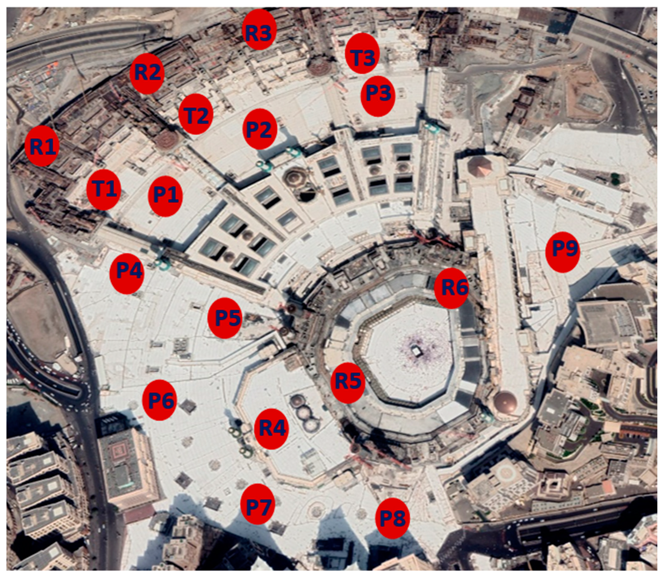
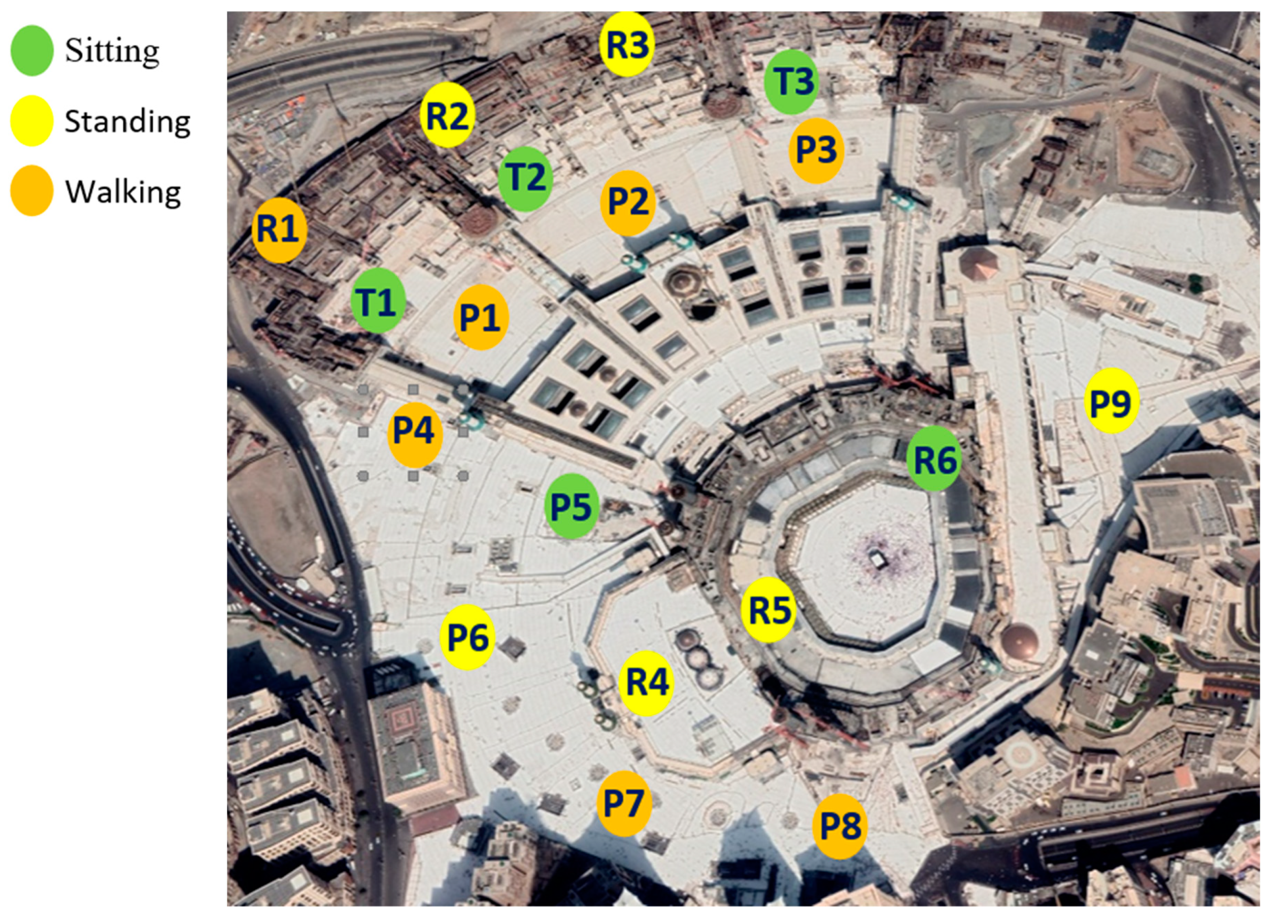
Eighteen locations were selected, as shown in Figure 2. Six points were chosen on the roofs (R1 to R6), three points on the first level of the terraces (T1 to T3), and nine on the piazza level (P1 to P9). Points R1 to R3 are found on the top of the terrace step, while R4 to R6 exist on the roof of the old Holy Mosque. On the other hand, locations P1 to P3 are located on the piazza between terraces and the third extension of the Holy Mosque. P4 and P5 are located on the piazza outside the third expansion. Point 9 is located on the piazza adjacent to the Masa’a. Finally, points P6 to P8 are located on the piazza of the old Holy Mosque. The degree of comfort of the prayers/visitors in the Holy Mosque area was rated: sitting/standing/walking level or discomfort. Alternatives were recommended to protect the prayers/visitors if they felt discomfort in some locations.

2.3. The Air Quality (the Calm Wind Locations)

The exact eighteen sites for the case of the prayers comfort were selected, as shown in Figure 2. The stagnant wind locations in the exterior areas of the Holy Mosque were checked. Some practical solutions were recommended to improve the air quality if there was the need.

3. The CFD Model

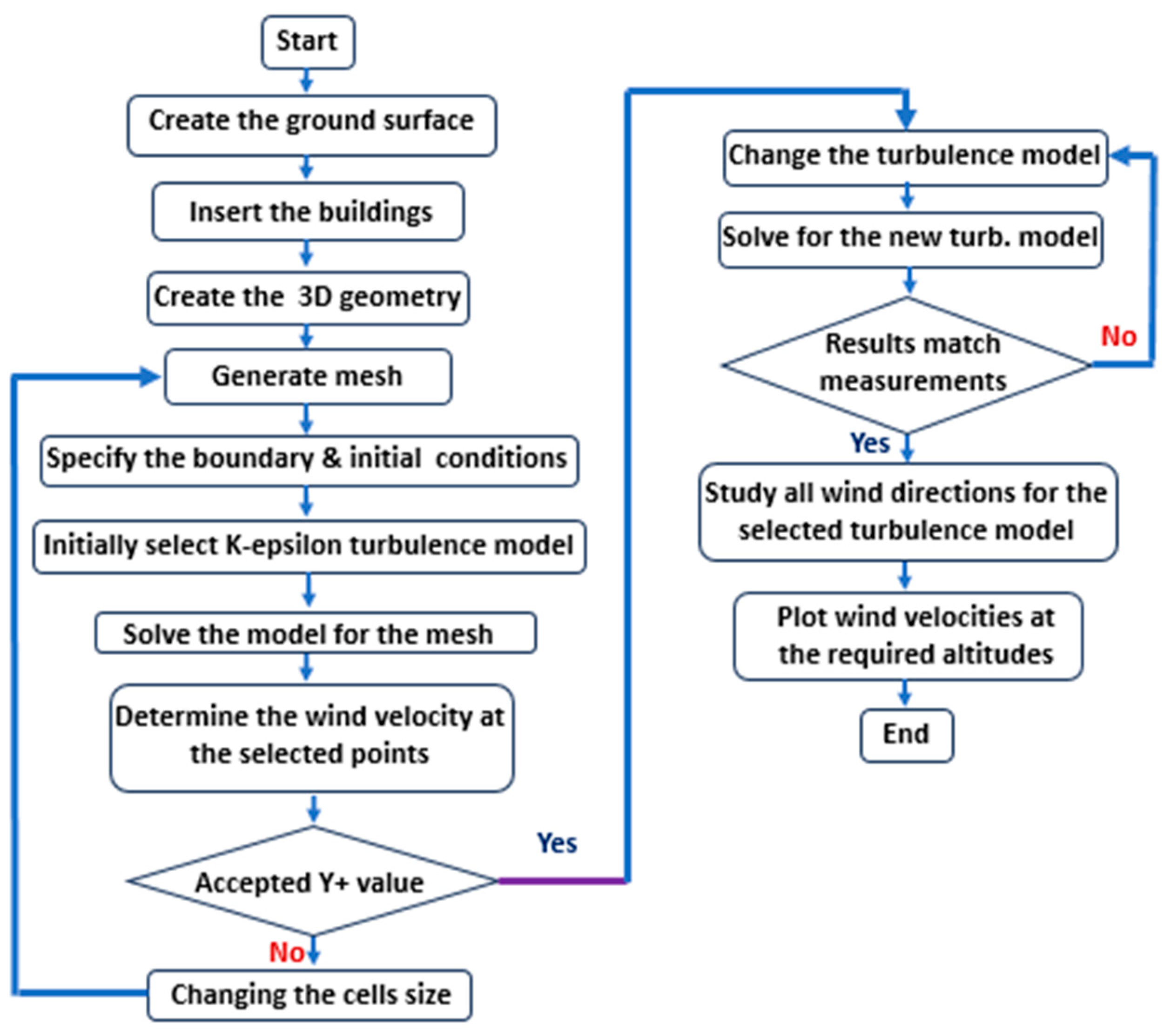
ANSYS Fluent 16 [61] was used to develop the 3D CFD simulation of the Holy Mosque area. The following items were briefed below: the model’s geometry, the grid generation and sensitivity analysis, the sensitivity of the turbulence model and the CFD model validation, the wind speeds and directions, assumptions, and simplifications, the boundary conditions, and the solver parameters. The gust wind speed and the speed for the environmental studies were discussed under the studied area of the Holy Mosque and the environmental wind design criteria, respectively. Figure 3 shows the flow chart that summarizes the adopted numerical methodology in this study.

3.1. The Geometry of the Model

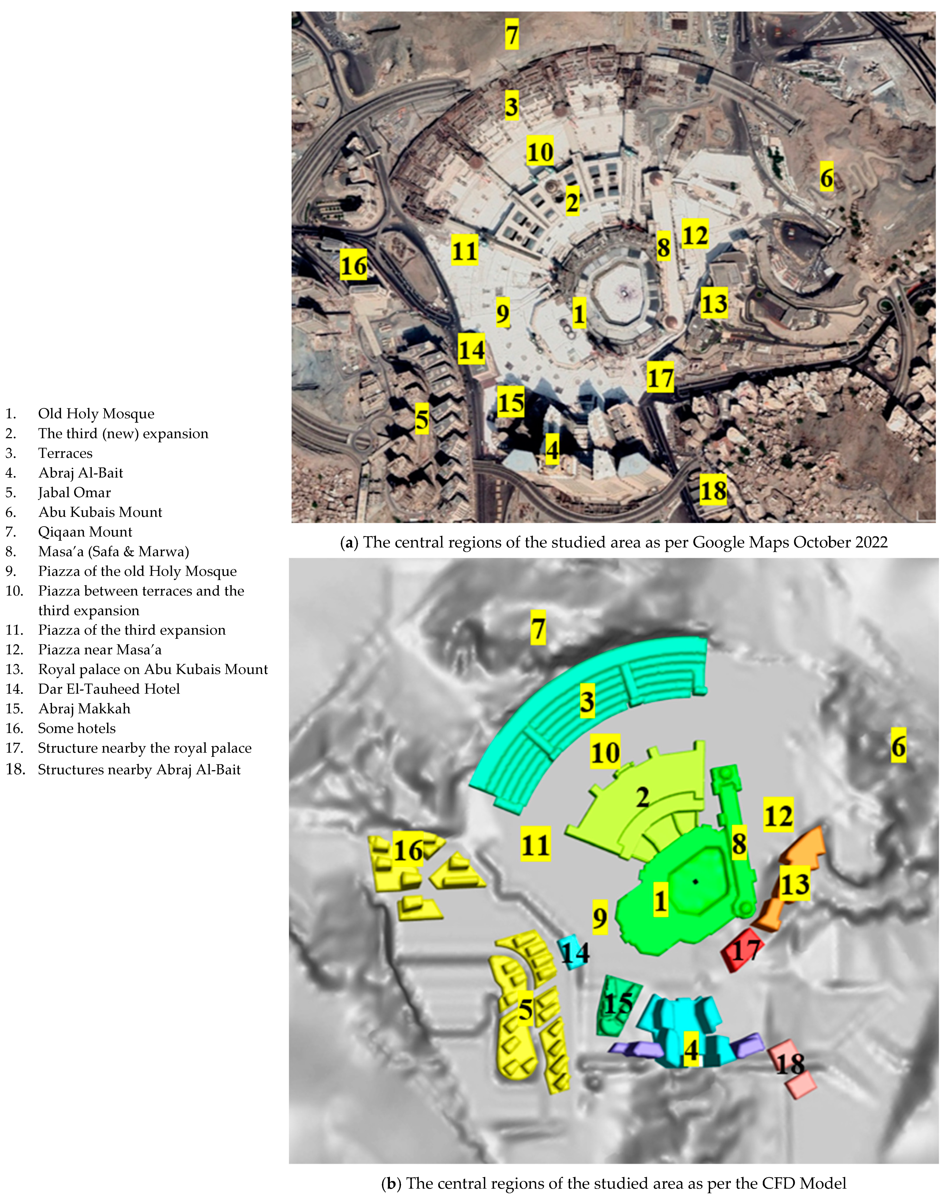
The 3D model has a square base with a side length of 1.8 km. The actual terrain of the studied area was considered by using the digital elevation model (DEM) for the Holy Mosque area to create the existing terrain surface in the model. Then, the main buildings were added to the model, such as the old Holy Mosque, the third expansion of the Holy Mosque, the terraces, the piazza of the old Holy Mosque, the piazza between the terraces and the third expansion, Jabal Omar structures, the royal palace on Abu Kubais mount, Dar El-Tauheed, Abraj Makkah, a part of the Abu Kubais mount, a part of the Qiqaan Mount and other hotel buildings, as shown in Figure 4a.
Figure 4b shows the main features of the studied area in the CFD simulation compared to the actual case study in Figure 4a. Any new nearby tall buildings or features in the studied area can be added to the current CFD model to keep it valid for future studies.

3.2. The Grid Generation and Sensitivity Analysis

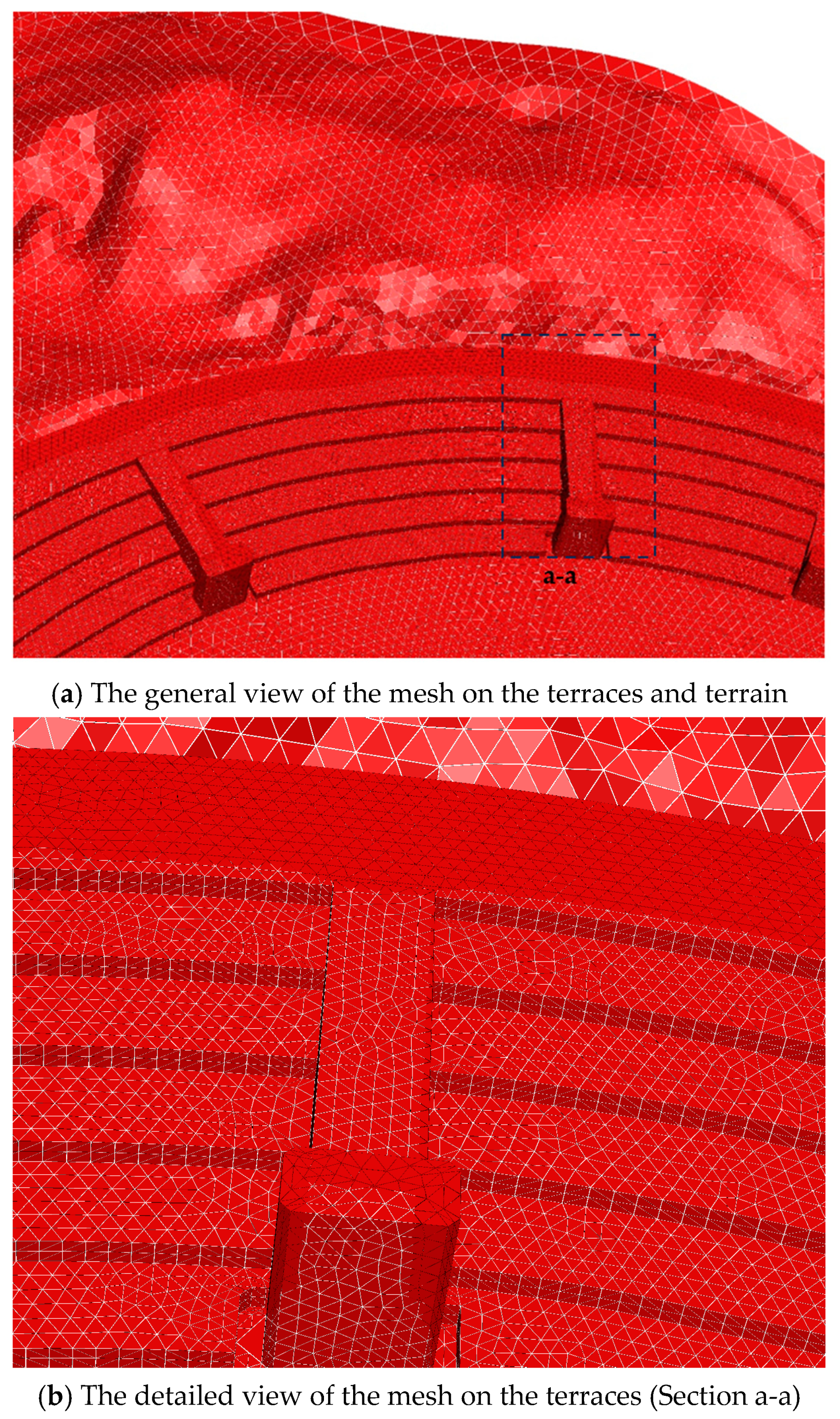
The accuracy of the results achieved from the CFD modeling significantly depends on the mesh quality, which also has implications for model convergence. This research applied a non-uniform mesh to the volumes of all CFD models. The grid was smoothened around the Holy Mosque structures and its piazza, which were the main areas of the current study. Different mesh sizes were generated to investigate the solution of independence from the grid. Grid sensitivity analysis was used to validate the CFD model. Four mech sizes were assumed to select the suitable size. These meshes were 977,408, 1,572,575, 2,403,713, and 3,625,124 tetrahedral cells. The mesh of 2.4 million cells, shown in Figure 5a,b, was chosen with a maximum expected difference in the velocity results of less than 1.5%, with a reduced consumed time of more than 70%. Also, the generated mesh was assessed by calculating the non-dimensional wall distance for a wall-bounded flow (y+), where the first layer of grid points on all the students was carefully taken in the near-wall mesh zone to keep the y+ value within an acceptable limit (the maximum below in this study was 10). The minimum volume of the cell size was 2.637 × 10⁻² m3, and 4.78 × 10³ m3 was the maximum cell size. Also, the maximum aspect ratio was 33.0156, and the minimum orthogonal quality was 0.0260305.

3.3. The Sensitivity of the Turbulence Model and the CFD Model Validation

The majority of the CFD outdoor wind models for different cases of the study, such as the current research, used K-ε turbulence models [62,63,64,65,66,67,68,69,70,71,72,73,74,75,76,77,78,79,80,81]: whereas the majority of the researchers used the standard K-ε turbulence model [62,63,64,65,66,67,68,69,70,71,72,73], some [74,75,76] used RNG K-ε turbulence model and others [77,78,79,80,81] used the Renormalization k-ε turbulence model. On the other hand, some researchers used large eddy simulation (LES) turbulence models such as [82,83,84,85].
This research studied the sensitivity of K-ε turbulence models, the standard, RNG, and realizable K-ε turbulence models where three points (T1, P4, and P9, as shown in Figure 2) were selected at different altitudes. The results of all the studied turbulence models were compared with those obtained by the wind-tunnel study conducted by Wacker-Ingenieure-Wind Engineering [confidential studies]. The standard K-ε turbulence model obtained the best results. The wind velocities and the wind loads were validated with maximum discrepancies of less than 10%.

3.4. The Wind Speeds and Directions

The wind levels for the Hajj months is presented in research [50]. In comparison, the wind levels in Holy Makkah for the entire year is shown in study [86]. Also, the wind speed in Holy Makkah is less than 10 km/h for nearly 22.9% of the year, between 10–20 km/h for almost 32% of the year, and more than 40 km/h for 3.5% of the year. Also, the mean wind speed is nearly 32 km/h throughout the year. The prevailing wind directions in Holy Makkah are northwest and southwest [86].
According to the Saudi Building Code, the maximum wind gust speed in Jeddah and Taif cities is 152 km/h. No gust wind speed is specified in the Holy Makkah. Therefore, it can be considered the same in Jeddah and Taif. The terrain exposure constants are relevant to category B.
Sixteen wind directions were studied with an equal interval of 22.5 o to cover all the possible directions. These sixteen wind directions are N, NNE, NE, ENE, E, ESE, SE, SSE, S, SSW, SW, WSW, W, NWN, NW, and NNW.

3.5. Assumptions and Simplifications

The assumptions and the simplifications, which were assumed in this study, are listed below:
  • There is no thermal effect considered.
  • All short buildings around the Holy Mosque were ignored.
  • Any interior locations inside the old Holy Mosque and their expansions were excluded.
  • All areas nearby the existing internal mechanical ventilation were excluded from the present study.
  • Details of the Holy Mosque, such as the minarets and the domes, were discarded.

3.6. The Boundary Conditions and the Solver Parameters

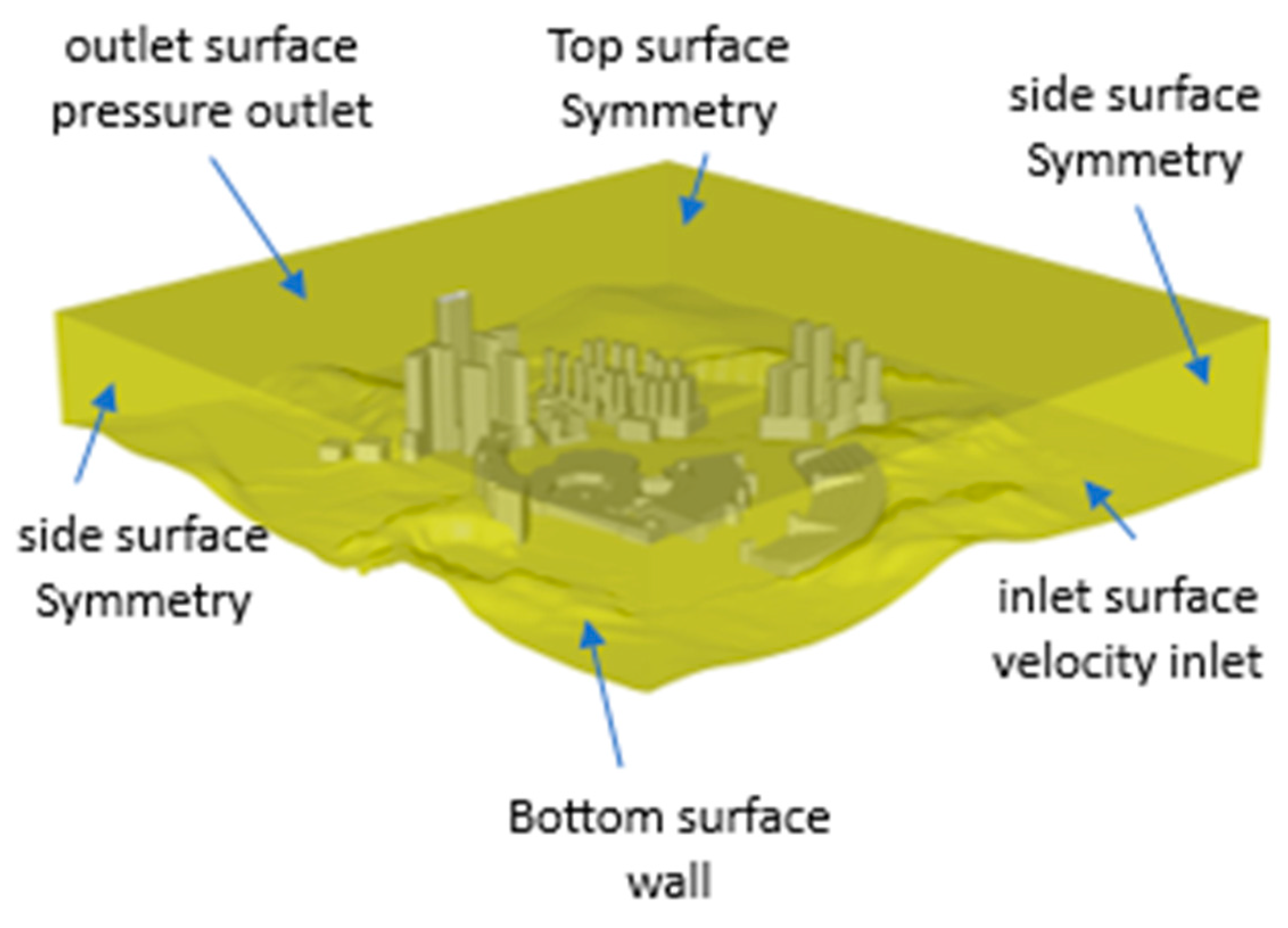
The main solver parameters and the boundary condition of the current CFD model are listed in Table 1. The flowchart of the study is illustrated in Figure 6.

4. Results and Discussion

Different models were developed in this research study, where sixteen wind directions were conducted for each model. The first model was performed to study the wind velocities on the entire Holy Mosque and its piazza as its current status. Another model was used after adding the collapsed tower crane in 2015 to the Holy Mosque model. The last model was the collapsed tower crane in an open area. The results of all the models can be found below.

4.1. The Wind Gust Results

All sixteen wind directions were studied for the twenty-four locations of the current working cranes and the location of the collapsed tower crane, as shown in Figure 1. The wind velocities in the Holy Mosque area were generally reduced because of the development of new buildings around the Holy Mosque. But the wind gust risk increases in some wind directions due to the downwashing over the tall buildings and channeling between buildings. The wind velocities were determined at all studied places from all wind directions. Then, the maximum wind velocity at each location was compared to the wind velocity in the case of an open area. The discussion below can be divided into the existing cranes on the terraces, the third expansion, and the old Holy Mosque.

4.1.1. The Cranes on the Terraces

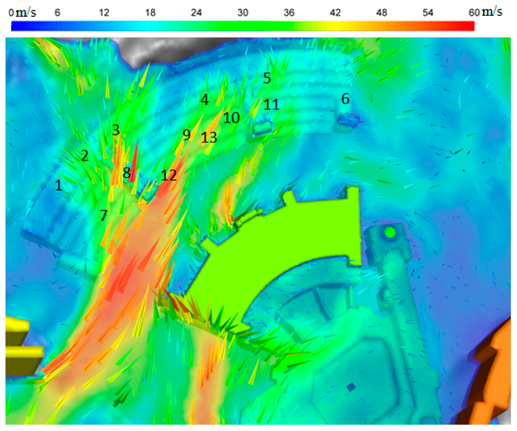
Thirteen cranes exist on the terraces, as shown in Figure 1a. Three exist on the top of the terraces, which are 1, 2, and 3. All the other cranes are found on different step levels. The wind speeds at 5.0 m higher than the base level of each crane were calculated for each wind direction. Then, they were compared to those in the case of open areas. In general, the wind speeds for all the cranes inside the Holy Mosque area are remarkably less than the speeds in the case in open space except for some limited wind directions, where the wind speeds in the Holy Mosque are higher than those in open spaces. Crane 11 is the only exception, where the maximum wind speed inside the Holy Mosque is nearly equal to that in an open space. The worst-case scenarios for the wind directions for most of the thirteen cranes are the south wind, as shown in Figure 7, and the south-southwest wind. The west-southwest wind is critical for cranes at locations 7, 10, and 13. Cranes at locations 4, 6, 7, 9, 12, and 13 have the most fundamental forces of wind increase by nearly 30% compared with the wind speeds in an open area. All other cranes at locations 1, 2, 3, 5, 8, and 10 show an increase in the actual wind speeds at Holy Mosque than those in an open area by 10–20%.

4.1.2. The Cranes on the Third Expansion

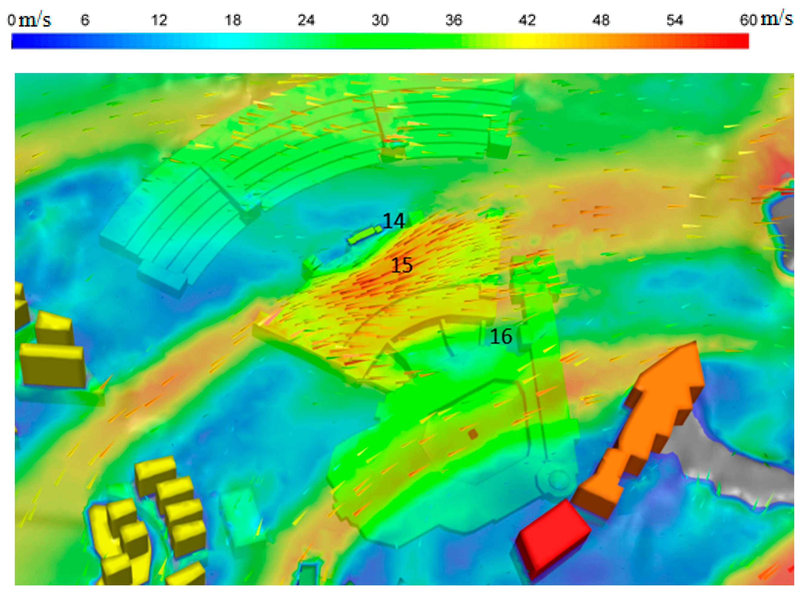
Three crane locations were considered in the current study for the third expansion of the Holy Mosque at locations 14–16. A strong wind current is expected to attack the roof surface of the third expansion of the Holy Mosque in case of blowing wind from the south-southwest direction for the three locations. The channeling between the Jabal Omer buildings and the Abraj Al-Bait increases the wind velocity, and downwashing over the Abraj Makkah tower directs the strong wind current to attack the crane at location 15 and consequently, the ceremonial dome, as shown in Figure 8. The wind velocity is increased by about 25%, compared to that in an open area. Cranes at locations 14 and 16 have a lower wind impact since their bases rested on the piazza, not on the roof of the expansion like crane 15.

4.1.3. The Cranes on the Old Holy Mosque and the Masa’a

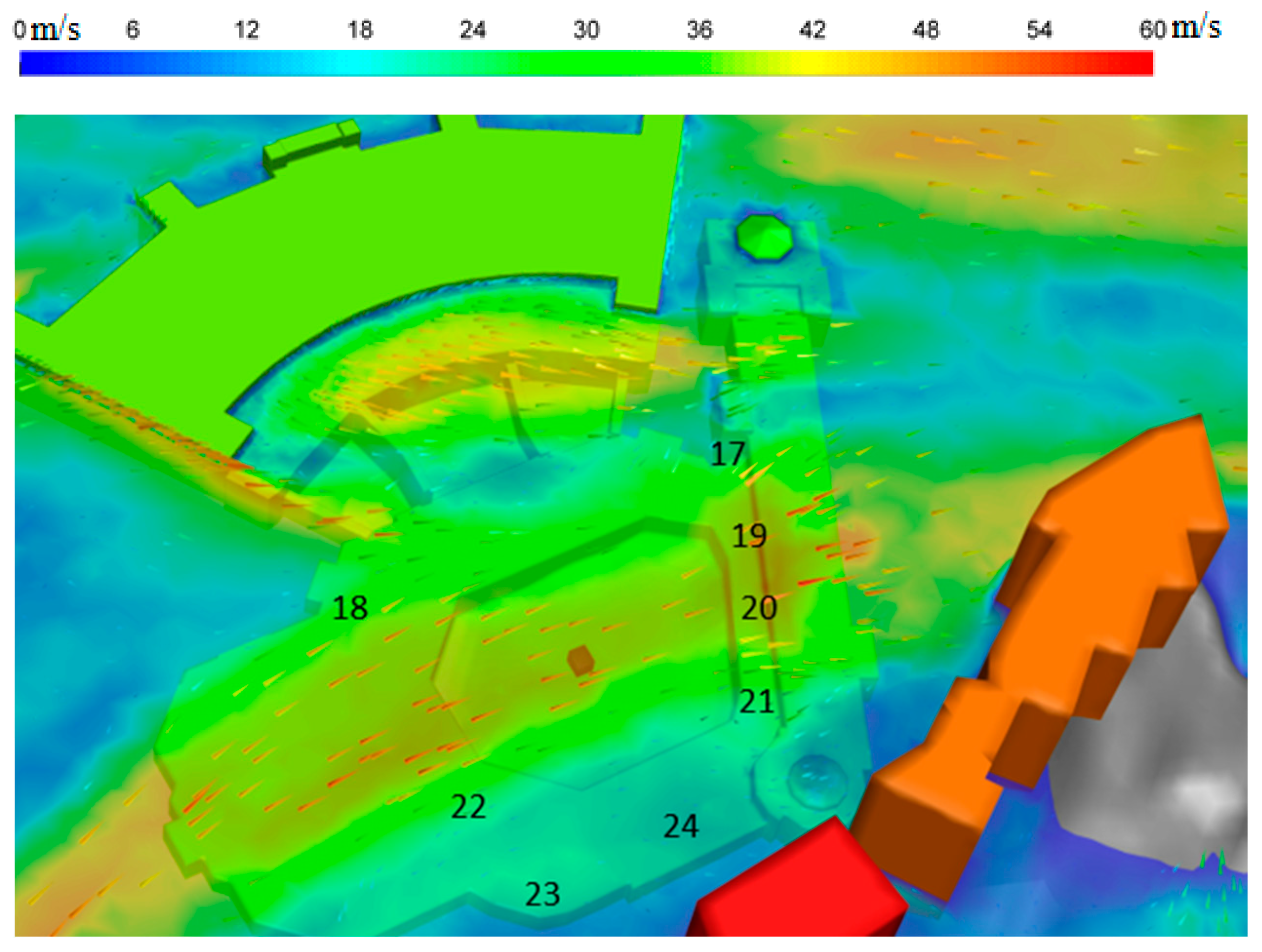
Cranes at locations 18, 22–24 are considered on the old Holy Mosque. On the other hand, the cranes at locations 17, 19–21 are on the Masa’a. The worst-case scenarios for almost all cranes are the south-southwest and west-southwest wind directions when the wind current develops from channeling between Abraj Makkah and Abraj Al-Bait and down-washing over both structures. Figure 9 illustrates the velocity vectors for the south-southwest wind direction attacking the old Holy Mosque and the Masa’a. The wind velocities at the cranes on the Masa’a increased by 25–30% compared to the wind in an open area. The wind speeds at cranes 18, 23, and 24 increase by up to 30% compared to the speeds in open space. The crane at location 22 has an increase in wind velocity of nearly 20% compared to that in open space.

4.1.4. The Case of the Tower Crane Accident in 2015 (Location 25)

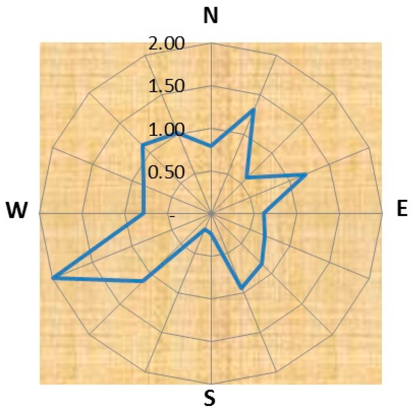
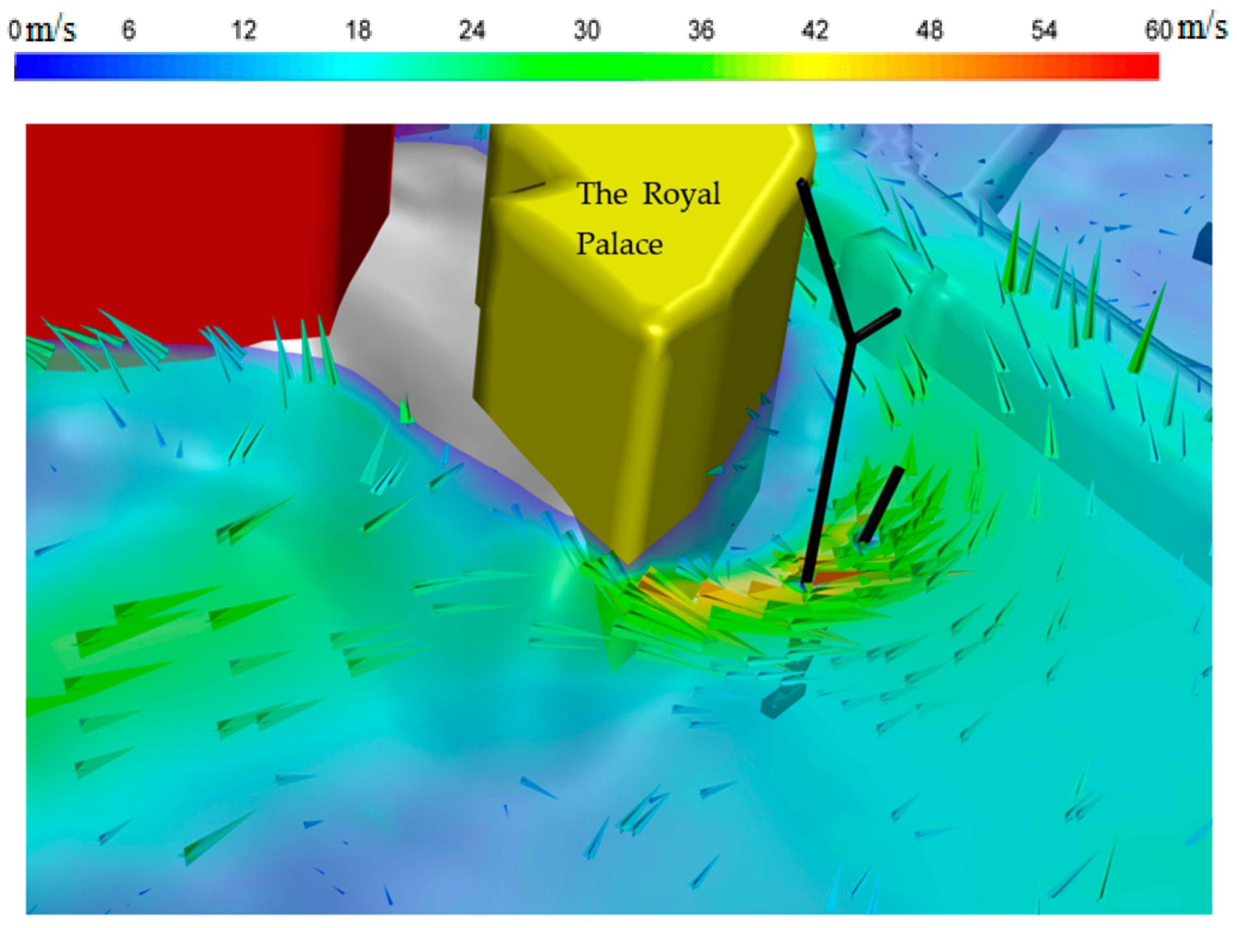
The overturning bending moments acting on the tower crane in the actual location were compared with those on the crane in an open area for the sixteen wind directions, as shown in Figure 10. The wind forces acting on the tower crane were considerably limited to the wind blowing from 10 out of the 16 known directions. However, the bending moment (overturning moment) values in the actual case inside the Holy Mosque were more than those in an open area in four wind directions. These four critical wind directions were north-northeast, east-northeast, northwest, and west-southwest. However, the ratio between the bending moment in an open area to that in an open space for the actual case is maximum in the west-southwest direction. The ultimate overturning moment, acting on the tower crane, occurred in the north-northeast wind direction, which was the case during the collapse of the tower crane. The overturning moment on the tower crane was 30% higher than in an open area. Figure 11 illustrates the contour of the wind velocity at the top of the Masa’a level.

4.2. The Comfort of the Prayers/Visitors

The pedestrian comfort level was checked in all wind directions for all mentioned locations in Figure 2. This study showed that all the places have different comfort levels (sitting, standing, and walking) to an expected return frequency of 20%. As shown in Figure 12, green dots represent the locations that fulfill the sitting comfort level, yellow for the standing comfort level, and orange for areas of the walking comfort level. The results of this study can be capsulated in the following points:
  • The wind speeds are at the walking comfort level in all locations on the piazza except P5, P6, and P9.
  • The locations P6 and P9 are at a standing comfort level.
  • The location P5 is at sitting comfort level.
  • P7 and P8 are in the walking comfort level and have the maximum wind speed out of the eighteen points.
  • The wind speed at point R1 on the terraces is at the walking comfort level, while points R2 and R3 are at the standing comfort level.
  • The wind speeds on the top of the old Holy Mosque at locations R4 and R5 are at the standing comfort level. On the other hand, location R6 is at the sitting comfort level.
  • The wind speeds on the first level of the terraces T1, T2, and T3 are at the sitting comfort level.

4.3. The Air Quality

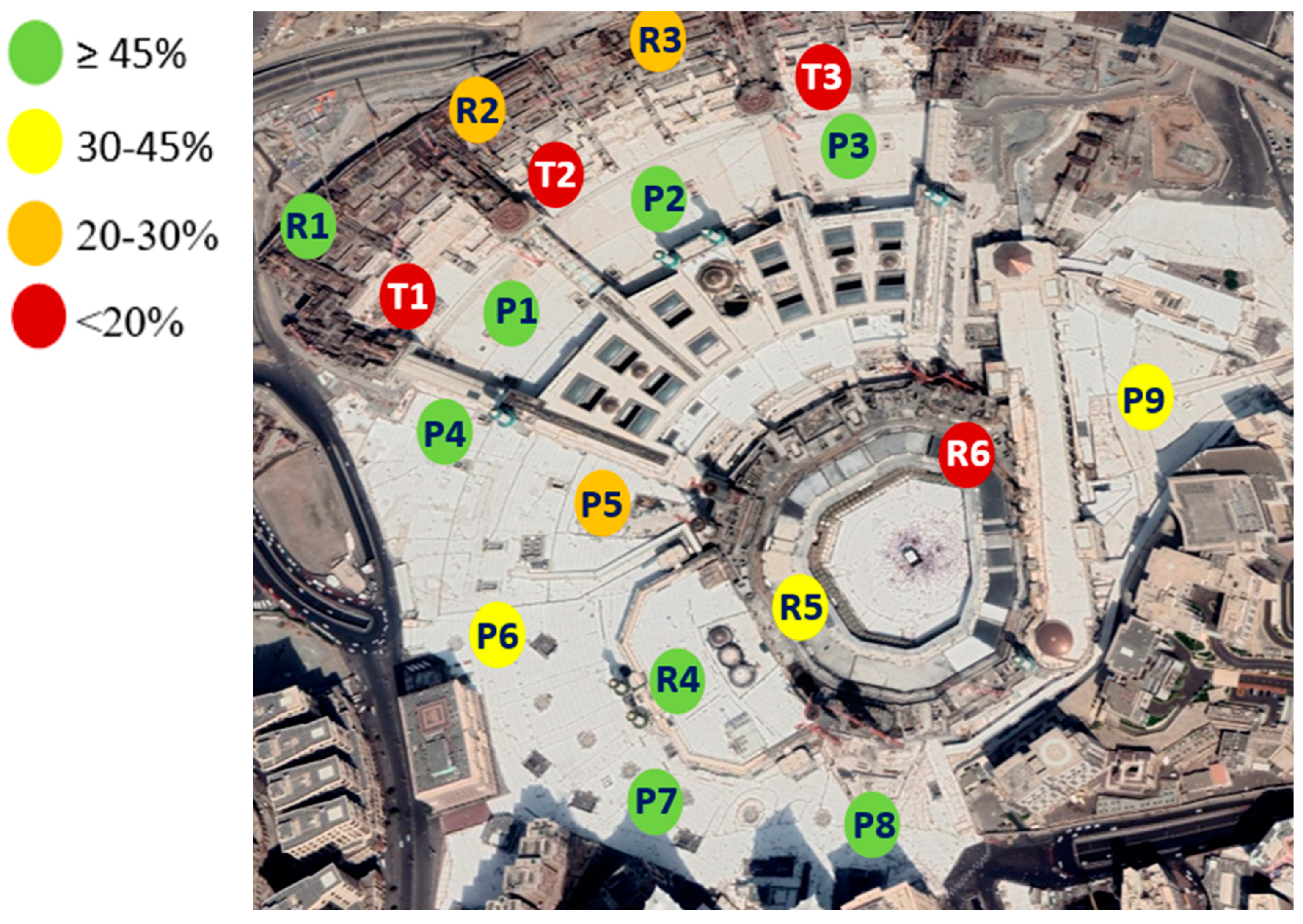
All areas nearby the existing internal mechanical ventilation were excluded from the present study. Using the Holy Makkah wind data, the average wind speed throughout the year in Holy Makkah was classified into four categories. As shown in Figure 13, red dots represent locations where the criterion mean wind speed of 1.5 m/s is exceeded less than 20% of the time; orange for 20% to 30%, yellow for 30% to 45%, and green for areas where the mean wind speed criterion of 1.5 m/s is exceeded more than 45% of the time. Since there is no Saudi standard for such a case, the last category (>45%) is recommended in this research to maintain the best air quality in the Holy Mosque area. The results show that all the selected points on the piazza have good ventilation except location P5 has relatively poor ventilation of 20–30% because it is on one of the confined corners. Such a site may need a source of mechanical ventilation. Also, locations P6 and P9 have relatively good ventilation, 30–45%. Location R4 on the Holy Mosque roof has good ventilation, while point R5 has reasonably good ventilation, 30–45%, and point R6 has poor ventilation. Location R1 on the top of the terraces also has good ventilation (>45%), while R2 and R3 have relatively poor ventilation, 20–30%. The ventilation is low on the lower terraces’ T1, T2, and T3 levels.

5. Conclusions and Recommendations

The 3D CFD model was developed, having a square base with a side length of 1.8 km, using ANSYS FLUENT. The actual terrain of the studied area was considered by using the digital elevation model (DEM) for the Holy Mosque area to create the existing terrain surface in the model. Then, the main buildings were added to the model, such as the old Holy Mosque, the third expansion of the Holy Mosque, the terraces, the piazza of the old Holy Mosque, the piazza between the terraces and the third expansion, Jabal Omar structures, the royal palace on Abu Kubais mount, Dar El-Tauheed, Abraj Makkah, a part of the Abu Kubais mount, a part of the Qiqaan Mount and other hotel buildings. In this research, three goals were tackled: the safety of the working cranes and the case of the collapsed tower crane at the Holy Mosque piazza in 2015, the wind comfort degree of the prayers/visitors, and locations having calm wind, which expose to lower air quality.
Twenty-five locations were selected for the gusting effects on almost all currently working cranes. The wind speeds at 5.0 m higher than the base level of each crane were calculated for each wind direction. Then, they were compared to those in the case of open areas. Thirteen cranes are on the terraces on different levels. Four crane sites are on the top of the Masa’a. Another three cranes place to serve the third expansion of the Mosque, four cranes are on the roof of the old Holy Mosque, and the last is the location of the collapsed tower crane. Generally, the gust wind speeds for all the crane locations inside the Holy Mosque area are remarkably lower than those in open space except for some limited wind directions. However, almost all the cranes are exposed to higher wind speeds than the open area values for a few wind directions. The worst-case scenarios for the wind directions for most of the thirteen cranes on the terraces are the south-southeast and the south wind. The wind speeds increase at the crane locations between 10–30% compared to those in open areas.
The south-southwest wind direction is the critical direction for the cranes on the Mosque expansion, where the wind velocity is increased up to 25% compared to those in open space. The channeling between the Jabal Omer buildings and the Abraj Al-Bait increases the wind velocity, and downwashing over the Abraj Makkah tower directs the strong wind current to attack the ceremonial dome and the cranes surrounding it. It is recommended to finalize the work of the cranes on the Masa’a, the minarets, and the moving dome before others or to change their locations.
The south-southwest and west-southwest are the critical wind directions for most of the locations of the eight cranes on the top of the old Holy Mosque and the Masa’a, where the wind speeds increase at the crane locations between 20–30% compared to those in open areas. The worst-case scenarios for almost all cranes are the south-southwest and west-southwest wind directions when the wind current develops from channeling between Abraj Makkah and Abraj Al-Bait and down-washing over both structures. Additionally, it is suggested to lower the crane boom if it is at rest and stop working on windy days.
The case of the collapsed tower crane in 2015 was studied. The study revealed that the gusting wind was only critical from 5 directions out of 16. The gusting wind causing the collapse was blowing from one of them when the overturning moment increased by 30% compared to the case in open space.
The wind comfort of the prayers/visitors study shows that all the places have different comfort levels (sitting, standing, and walking) to an expected return frequency of 20%. All the areas on the top of the piazza have walking/standing comfort levels, except closed areas, which have sitting comfort levels. The northwest side of the terrace’s top surface has a walking comfort level, while the rest has a standing comfort level. The top of the Holy Mosque has a standing/sitting comfort level. The wind speeds on the lowest level of the terraces are at the sitting comfort level.
Regarding air quality, the minimum mean speed is assumed to be 1.5 m/s since there are no specified worldwide criteria for ventilation requirements in outdoor sub-urban environments. Since there is no Saudi standard for such a case, the target of exceeding the mean speed 45% of the time is recommended in this research to maintain the best air quality in the Holy Mosque area. The results show that all areas on the piazza have good ventilation, except areas in confined corners with poor ventilation. Also, the places at the back of the Masa’a and nearby Dar El-Tauheed Hotel have relatively good ventilation. The west side of the Holy Mosque roof has good ventilation, while its northeast has relatively poor ventilation. The northwest of the upper level of the terraces has good ventilation. In contrast, the north and east sides have relatively poor ventilation. Ventilation is lacking on the lower terrace levels.
It is recommended to
  • Finalize the work of the cranes on the Masa’a, the minarets, and the ceremonial dome before others.
  • Change the locations of cranes exposed to strong wind and/or move their bases to lower levels, if possible.
  • Lower the crane boom if it is at rest.
  • Stop working on windy days.
  • Study the effect of using mechanical ventilation by using large-scale fans. A wind tunnel or CFD should simulate the case to ensure sufficient mechanical ventilation.
  • Using large-scale fans without prior modeling may help spread infectious diseases.
  • Using natural ventilation is much better than mechanical ventilation.
  • Study the possibility of improving the natural ventilation of the Holy Mosque by pruning the Abu Kubais Mount in the east and/or Qiqaan Mounts in the north.
  • It is not recommended to have new tall buildings surrounding the Holy Mosque, especially from the north and the east, except after studying the impact on the air quality using either wind tunnel or CFD simulations.

Funding

This research received no external funding.

Data Availability Statement

No new data were created or analyzed in this study. Data sharing is not applicable to this article.

Conflicts of Interest

The author declares no conflict of interest.

References

  1. Mendis, P.; Ngo, T.; Haritos, N.; Hira, A.; Samali, B.; Cheung, J. Wind Loading on Tall Buildings. Electron. J. Struct. Eng. 2007, 7, 41–54. [Google Scholar] [CrossRef]
  2. Thordal, M.S.; Bennetsen, J.C.; Koss, H.H.H. Review for practical application of CFD for the determination of wind load on high-rise buildings. J. Wind. Eng. Ind. Aerodyn. 2019, 186, 155–168. [Google Scholar] [CrossRef]
  3. Farouk, M.I.; Mourad, S.A.; Salaheldin, A.S. Numerical simulation of wind effects on an airport air traffic control tower. In WIT Transactions on the Built Environment; WIT Press: Billerica, MA, USA, 2007; Volume 92. [Google Scholar] [CrossRef] [Green Version]
  4. Dagnew, A.K.; Bitsuamlak, G.T. Computational evaluation of wind loads on buildings: A review. Wind. Struct. 2013, 16, 629–660. [Google Scholar] [CrossRef]
  5. Tamura, T.; Nozawa, K.; Kondo, K. AIJ guide for numerical prediction of wind loads on buildings. J. Wind. Eng. Ind. Aerodyn. 2008, 96, 1974–1984. [Google Scholar] [CrossRef]
  6. Farouk, M.I. Check the comfort of occupants in high rise building using CFD. Ain Shams Eng. J. 2016, 7, 953–958. [Google Scholar] [CrossRef] [Green Version]
  7. Hou, F.; Jafari, M. Investigation approaches to quantify wind-induced load and response of tall buildings: A review. Sustain. Cities Soc. 2020, 62, 102376. [Google Scholar] [CrossRef]
  8. Kwok, K.C.; Hitchcock, P.A.; Burton, M.D. Perception of vibration and occupant comfort in wind-excited tall buildings. J. Wind. Eng. Ind. Aerodyn. 2009, 97, 368–380. [Google Scholar] [CrossRef]
  9. Elias, S.; Matsagar, V. Wind response control of tall buildings with a tuned mass damper. J. Build. Eng. 2018, 15, 51–60. [Google Scholar] [CrossRef]
  10. Fu, L.; Hao, J.; He, D.; He, K.; Li, P. Assessment of vehicular pollution in China. J. Air Waste Manag. Assoc. 2001, 51, 658–668. [Google Scholar] [CrossRef] [Green Version]
  11. Rupp, R.F.; Vasquez, N.G.; Lamberts, R. A review of human thermal comfort in the built environment. Energy Build. 2015, 105, 178–205. [Google Scholar] [CrossRef]
  12. Cheng, V.; Ng, E.; Chan, C.; Givoni, B. Outdoor thermal comfort study in a sub-tropical climate: A longitudinal study based in Hong Kong. Int. J. Biometeorol. 2012, 56, 43–56. [Google Scholar] [CrossRef]
  13. Lai, D.; Lian, Z.; Liu, W.; Guo, C.; Liu, W.; Liu, K.; Chen, Q. A comprehensive review of thermal comfort studies in urban open spaces. Sci. Total. Environ. 2020, 742, 140092. [Google Scholar] [CrossRef]
  14. Potchter, O.; Cohen, P.; Lin, T.-P.; Matzarakis, A. Outdoor human thermal perception in various climates: A comprehensive review of approaches, methods and quantification. Sci. Total Environ. 2018, 631–632, 390–406. [Google Scholar] [CrossRef] [PubMed]
  15. Kamei, I.; Maruta, E. Study on wind environmental problems caused around buildings in Japan. J. Wind. Eng. Ind. Aerodyn. 1979, 4, 307–331. [Google Scholar] [CrossRef]
  16. Murakami, S.; Uehara, K.; Komine, H. Amplification of wind speed at ground level due to construction of high-rise building in urban area. J. Wind. Eng. Ind. Aerodyn. 1979, 4, 343–370. [Google Scholar] [CrossRef]
  17. Murakami, S.; Iwasa, Y.; Morikawa, Y. Study on acceptable criteria for assessing wind environment at ground level based on residents’ diaries. J. Wind. Eng. Ind. Aerodyn. 1986, 24, 1–18. [Google Scholar] [CrossRef]
  18. Penwarden, A.D.; Wise, A.F.E. Wind Environment around Buildings; HM Stationery Office: London, UK, 1975. [Google Scholar]
  19. Durgin, F.H. Pedestrian level wind studies at the Wright brothers facility. J. Wind. Eng. Ind. Aerodyn. 1992, 44, 2253–2264. [Google Scholar] [CrossRef]
  20. Isyumov, N. Studies of the pedestrian level wind environment at the boundary layer wind tunnel laboratory of the University of Western Ontario. J. Wind. Eng. Ind. Aerodyn. 1978, 3, 187–200. [Google Scholar] [CrossRef]
  21. Beranek, W.J. Wind Environment around Single Buildings of Rectangular Shape and Wind Environment around Building Configurations; Stevin-Laboratory of the Department of Civil Engineering, Delft University of Technology: Delft, The Netherlands, 1984. [Google Scholar]
  22. Stathopoulos, T. Wind environmental conditions around tall buildings with chamfered corners. J. Wind. Eng. Ind. Aerodyn. 1985, 21, 71–87. [Google Scholar] [CrossRef]
  23. Tsang, C.; Kwok, K.; Hitchcock, P. Wind tunnel study of pedestrian level wind environment around tall buildings: Effects of building dimensions, separation and podium. Build. Environ. 2012, 49, 167–181. [Google Scholar] [CrossRef]
  24. Xu, X.; Yang, Q.; Yoshida, A.; Tamura, Y. Characteristics of pedestrian-level wind around super-tall buildings with various configurations. J. Wind. Eng. Ind. Aerodyn. 2017, 166, 61–73. [Google Scholar] [CrossRef]
  25. Mittal, H.; Sharma, A.; Gairola, A. A review on the study of urban wind at the pedestrian level around buildings. J. Build. Eng. 2018, 18, 154–163. [Google Scholar] [CrossRef]
  26. Irwin, H. A simple omnidirectional sensor for wind-tunnel studies of pedestrian-level winds. J. Wind. Eng. Ind. Aerodyn. 1981, 7, 219–239. [Google Scholar] [CrossRef]
  27. Uematsu, T.; Yamada, K.-I.; Matsuno, H.; Nakashima, M. The Measurement of Haloperidol and Reduced Haloperidol in Neonatal Hair as an Index of Placental Transfer of Maternal Haloperidol. Ther. Drug Monit. 1991, 13, 183–187. [Google Scholar] [CrossRef]
  28. Wu, H.; Stathopoulos, T. Wind-Tunnel Techniques for Assessment of Pedestrian-Level Winds. J. Eng. Mech. 1993, 119, 1920–1936. [Google Scholar] [CrossRef]
  29. Jackson, P. The evaluation of windy environments. Build. Environ. 1978, 13, 251–260. [Google Scholar] [CrossRef]
  30. Melbourne, W. Criteria for environmental wind conditions. J. Wind. Eng. Ind. Aerodyn. 1978, 3, 241–249. [Google Scholar] [CrossRef]
  31. Hunt, J.; Poulton, E.; Mumford, J. The effects of wind on people; New criteria based on wind tunnel experiments. Build. Environ. 1976, 11, 15–28. [Google Scholar] [CrossRef]
  32. Durgin, F.H. Pedestrian level wind criteria using the equivalent average. J. Wind. Eng. Ind. Aerodyn. 1997, 66, 215–226. [Google Scholar] [CrossRef]
  33. Arens, E.; Ballanti, D.; Bennett, C.; Guldman, S.; White, B. Developing the San Francisco wind ordinance and its guidelines for compliance. Build. Environ. 1989, 24, 297–303. [Google Scholar] [CrossRef] [Green Version]
  34. Durgin, F.H. Proposed guidelines for pedestrian level wind studies for Boston—Comparison of results from 12 studies. Build. Environ. 1989, 24, 305–314. [Google Scholar] [CrossRef]
  35. Willemsen, E.; Wisse, J.A. Design for wind comfort in The Netherlands: Procedures, criteria and open research issues. J. Wind. Eng. Ind. Aerodyn. 2007, 95, 1541–1550. [Google Scholar] [CrossRef]
  36. Ng, E. Policies and technical guidelines for urban planning of high-density cities—Air ventilation assessment (AVA) of Hong Kong. Build. Environ. 2009, 44, 1478–1488. [Google Scholar] [CrossRef]
  37. Soligo, M.J.; Irwin, P.A.; Williams, C.J.; Schuyler, G.D. A comprehensive assessment of pedestrian comfort including thermal effects. J. Wind. Eng. Ind. Aerodyn. 1998, 77–78, 753–766. [Google Scholar] [CrossRef]
  38. Lawson, T.V.; Penwarden, A.D. The effects of wind on people in the vicinity of buildings. In Proceedings of the 4th International Conference on Wind Effects on Building and Structures, London, UK, 9 August 1975. [Google Scholar]
  39. Isyumov, N.; Davenport, A.G. The ground level wind environment in built-up areas. In Proceedings of the 4th International Conference on Wind Effects on Building and Structures, London, UK, 9 August 1975. [Google Scholar]
  40. Lawson, T.V. The Determination of the Wind Environment of a Building Complex before Construction; Report Number TVL; Department of Aerospace Engineering, University of Bristol: Bristol, UK, 1990; Volume 9025. [Google Scholar]
  41. Yip, C.; Chang, W.L.; Yeung, K.H.; Yu, I.T.S. Possible meteorological influence on the severe acute respiratory syndrome (SARS) community outbreak at Amoy Gardens, Hong Kong. J. Environ. Health 2007, 70, 39–47. [Google Scholar]
  42. Zhang, Y.; Kwok, K.; Liu, X.-P.; Niu, J.-L. Characteristics of air pollutant dispersion around a high-rise building. Environ. Pollut. 2015, 204, 280–288. [Google Scholar] [CrossRef]
  43. Van Doremalen, N.; Bushmaker, T.; Morris, D.H.; Holbrook, M.G.; Gamble, A.; Williamson, B.N.; Tamin, A.; Harcourt, J.L.; Thornburg, N.J.; Gerber, S.I.; et al. Aerosol and Surface Stability of SARS-CoV-2 as Compared with SARS-CoV-1. N. Engl. J. Med. 2020, 382, 1564–1567. [Google Scholar] [CrossRef] [PubMed]
  44. Coccia, M. How do low wind speeds and high levels of air pollution support the spread of COVID-19? Atmos. Pollut. Res. 2021, 12, 437–445. [Google Scholar] [CrossRef] [PubMed]
  45. Coccia, M. The effects of atmospheric stability with low wind speed and of air pollution on the accelerated transmission dynamics of COVID-19. Int. J. Environ. Stud. 2021, 78, 1–27. [Google Scholar] [CrossRef]
  46. Al-Jeelani, H.A. Evaluation of air quality in the Holy Makkah during Hajj season 1425 H. J. Appl. Sci. Res. 2009, 5, 115–121. [Google Scholar]
  47. Seroji, A.R. Particulates in the atmosphere of Makkah and Mina Valley during the Ramadan and Hajj seasons of 2004 and 2005. In Air Pollution XIX; Brebbia, C.A., Longhurst, J.W.S., Popov, V., Eds.; Wessex Institute of Technology: Southampton, UK, 2011; pp. 319–327. [Google Scholar]
  48. Habeebullah, T.M. An Analysis of Air Pollution in Makkah—A View Point of Source Identification. Environ. Asia 2013, 2, 11–17. [Google Scholar]
  49. Simpson, I.J.; Aburizaiza, O.S.; Siddique, A.; Barletta, B.; Blake, N.J.; Gartner, A.; Khwaja, H.; Meinardi, S.; Zeb, J.; Blake, D.R. Air Quality in Mecca and Surrounding Holy Places in Saudi Arabia During Hajj: Initial Survey. Environ. Sci. Technol. 2014, 48, 8529–8537. [Google Scholar] [CrossRef] [PubMed] [Green Version]
  50. Farahat, A.; Chauhan, A.; Al Otaibi, M.; Singh, R.P. Air Quality over Major Cities of Saudi Arabia During Hajj Periods of 2019 and 2020. Earth Syst. Environ. 2021, 5, 101–114. [Google Scholar] [CrossRef]
  51. Nayebare, S.R.; Aburizaiza, O.S.; Siddique, A.; Carpenter, D.O.; Hussain, M.M.; Zeb, J.; Aburiziza, A.J.; Khwaja, H.A. Ambient air quality in the holy city of Makkah: A source apportionment with elemental enrichment factors (EFs) and factor analysis (PMF). Environ. Pollut. 2018, 243, 1791–1801. [Google Scholar] [CrossRef]
  52. Munir, S.; Habeebullah, T.M.; Seroji, A.R.; Gabr, S.S.; Mohammed, A.M.; Morsy, E.A. Quantifying temporal trends of atmospheric pollutants in Makkah (1997–2012). Atmos. Environ. 2013, 77, 647–655. [Google Scholar] [CrossRef]
  53. Al-Jeelani, H.A. Air quality assessment at Al-Taneem area in the Holy Makkah City, Saudi Arabia. Environ. Monit. Assess. 2009, 156, 211–222. [Google Scholar] [CrossRef]
  54. Farouk, M. Three-Dimensional Dynamic Numerical Simulation of the Holy Mosque Area. 2023. Available online: https://easychair.org/publications/preprint/dGbCH (accessed on 30 May 2023). EasyChair Preprint no. 9865.
  55. Ascoura, I.E. Impact of Pilgrimage (Hajj) on the Urban Growth of the Mecca. J. Educ. Soc. Res. 2013, 3, 255. [Google Scholar] [CrossRef] [Green Version]
  56. Qin, R.; Yan, D.; Zhou, X.; Jiang, Y. Research on a dynamic simulation method of atrium thermal environment based on neural network. Build. Environ. 2012, 50, 214–220. [Google Scholar] [CrossRef]
  57. Yi, Y.K.; Malkawi, A. Site-specific optimal energy form generation based on hierarchical geometry relation. Autom. Constr. 2012, 26, 77–91. [Google Scholar] [CrossRef]
  58. Brahimi, T. Using Artificial Intelligence to Predict Wind Speed for Energy Application in Saudi Arabia. Energies 2019, 12, 4669. [Google Scholar] [CrossRef] [Green Version]
  59. Wijesooriya, K.; Mohotti, D.; Lee, C.-K.; Mendis, P. A technical review of computational fluid dynamics (CFD) applications on wind design of tall buildings and structures: Past, present and future. J. Build. Eng. 2023, 74, 106828. [Google Scholar] [CrossRef]
  60. Zhang, R.; Mirzaei, P.A. Virtual dynamic coupling of computational fluid dynamics-building energy simulation-artificial intelligence: Case study of urban neighbourhood effect on buildings’ energy demand. Build. Environ. 2021, 195, 107728. [Google Scholar] [CrossRef]
  61. ANSYS Fluent, Release 15; ANSYS, Inc.: Canonsburg, PA, USA, 2013.
  62. Richards, P.; Hoxey, R. Appropriate boundary conditions for computational wind engineering models using the k-ϵ turbulence model. J. Wind. Eng. Ind. Aerodyn. 1993, 46–47, 145–153. [Google Scholar] [CrossRef]
  63. Murakami, S. Computational wind engineering. J. Wind. Eng. Ind. Aerodyn. 1990, 36, 517–538. [Google Scholar] [CrossRef]
  64. Murakami, S. Current status and future trends in computational wind engineering. J. Wind. Eng. Ind. Aerodyn. 1997, 67–68, 3–34. [Google Scholar] [CrossRef]
  65. Bottema, M.; Leene, J.; Wisse, J. Towards forecasting of wind comfort. J. Wind. Eng. Ind. Aerodyn. 1992, 44, 2365–2376. [Google Scholar] [CrossRef]
  66. Stathopoulos, T. Computational wind engineering: Past achievements and future challenges. J. Wind. Eng. Ind. Aerodyn. 1997, 67–68, 509–532. [Google Scholar] [CrossRef]
  67. Stathopoulos, T. Pedestrian level winds and outdoor human comfort. J. Wind. Eng. Ind. Aerodyn. 2006, 94, 769–780. [Google Scholar] [CrossRef]
  68. Li, W.; Wang, F.; Bell, S. Simulating the sheltering effects of windbreaks in urban outdoor open space. J. Wind. Eng. Ind. Aerodyn. 2007, 95, 533–549. [Google Scholar] [CrossRef]
  69. Yoshie, R.; Mochida, A.; Tominaga, Y.; Kataoka, H.; Harimoto, K.; Nozu, T.; Shirasawa, T. Cooperative project for CFD prediction of pedestrian wind environment in the Architectural Institute of Japan. J. Wind Eng. Ind. Aerodyn. 2007, 95, 1551–1578. [Google Scholar] [CrossRef]
  70. Lin, B.; Li, X.; Zhu, Y.; Qin, Y. Numerical simulation studies of the different vegetation patterns’ effects on outdoor pedestrian thermal comfort. J. Wind. Eng. Ind. Aerodyn. 2008, 96, 1707–1718. [Google Scholar] [CrossRef]
  71. Farouk, M. Comparative study of hexagon & square windcatchers using CFD simulations. J. Build. Eng. 2020, 31, 101366. [Google Scholar] [CrossRef]
  72. Calautit, J.K.; Hughes, B.R. Wind tunnel and CFD study of the natural ventilation performance of a commercial multi-directional wind tower. Build. Environ. 2014, 80, 71–83. [Google Scholar] [CrossRef] [Green Version]
  73. Calautit, J.K.; Hughes, B.R.; Ghani, S.A. A numerical investigation into the feasibility of integrating green building technologies into row houses in the Middle East. Arch. Sci. Rev. 2013, 56, 279–296. [Google Scholar] [CrossRef]
  74. Ferreira, A.D.; Sousa AC, M.; Viegas, D.X. Prediction of building interference effects on pedestrian level comfort. J. Wind. Eng. Ind. Aerodyn. 2002, 90, 305–319. [Google Scholar] [CrossRef] [Green Version]
  75. Farouk, M.I.; Nassar, A.F.; Elgamal, M.H. Numerical Study of the Transmission of Exhaled Droplets between the Instructor and Students in a Typical Classroom. Appl. Sci. 2021, 11, 9767. [Google Scholar] [CrossRef]
  76. Zhang, A.; Gao, C.; Zhang, L. Numerical simulation of the wind field around different building arrangements. J. Wind. Eng. Ind. Aerodyn. 2005, 93, 891–904. [Google Scholar] [CrossRef]
  77. Blocken, B.; Carmeliet, J.; Stathopoulos, T. CFD evaluation of wind speed conditions in passages between parallel buildings—Effect of wall-function roughness modifications for the atmospheric boundary layer flow. J. Wind. Eng. Ind. Aerodyn. 2007, 95, 941–962. [Google Scholar] [CrossRef]
  78. Blocken, B.; Roels, S.; Carmeliet, J. Modification of pedestrian wind comfort in the Silvertop Tower passages by an automatic control system. J. Wind. Eng. Ind. Aerodyn. 2004, 92, 849–873. [Google Scholar] [CrossRef]
  79. Blocken, B.; Persoon, J. Pedestrian wind comfort around a large football stadium in an urban environment: CFD simulation, validation and application of the new Dutch wind nuisance standard. J. Wind. Eng. Ind. Aerodyn. 2009, 97, 255–270. [Google Scholar] [CrossRef]
  80. An, K.; Fung, J.; Yim, S.H.L. Sensitivity of inflow boundary conditions on downstream wind and turbulence profiles through building obstacles using a CFD approach. J. Wind. Eng. Ind. Aerodyn. 2013, 115, 137–149. [Google Scholar] [CrossRef]
  81. Tominaga, Y.; Mochida, A.; Murakami, S.; Sawaki, S. Comparison of various revised k–ε models and LES applied to flow around a high-rise building model with 1:1:2 shape placed within the surface boundary layer. J. Wind Eng. Ind. Aerodyn. 2008, 96, 389–411. [Google Scholar] [CrossRef]
  82. He, J.; Song, C.C. Evaluation of pedestrian winds in urban area by numerical approach. J. Wind. Eng. Ind. Aerodyn. 1999, 81, 295–309. [Google Scholar] [CrossRef]
  83. Cheng, Y.; Lien, F.; Yee, E.; Sinclair, R. A comparison of large Eddy simulations with a standard k–ε Reynolds-averaged Navier–Stokes model for the prediction of a fully developed turbulent flow over a matrix of cubes. J. Wind. Eng. Ind. Aerodyn. 2003, 91, 1301–1328. [Google Scholar] [CrossRef]
  84. Salim, S.M.; Buccolieri, R.; Chan, A.; DI Sabatino, S. Numerical simulation of atmospheric pollutant dispersion in an urban street canyon: Comparison between RANS and LES. J. Wind Eng. Ind. Aerodyn. 2011, 99, 103–113. [Google Scholar] [CrossRef]
  85. Daniels, S.J.; Xie, Z.-T. Overview of large-eddy simulation for wind loading on slender structures. Proc. Inst. Civ. Eng.-Eng. Comput. Mech. 2022, 175, 41–71. [Google Scholar] [CrossRef]
  86. Shehata, A.; Waheeb, S. Thermal Performance of Contemporary Residential Buildings in Hot-Arid Climates. J. Adv. Res. Dyn. Control Syst. 2018, 10, 1295–1303. [Google Scholar]
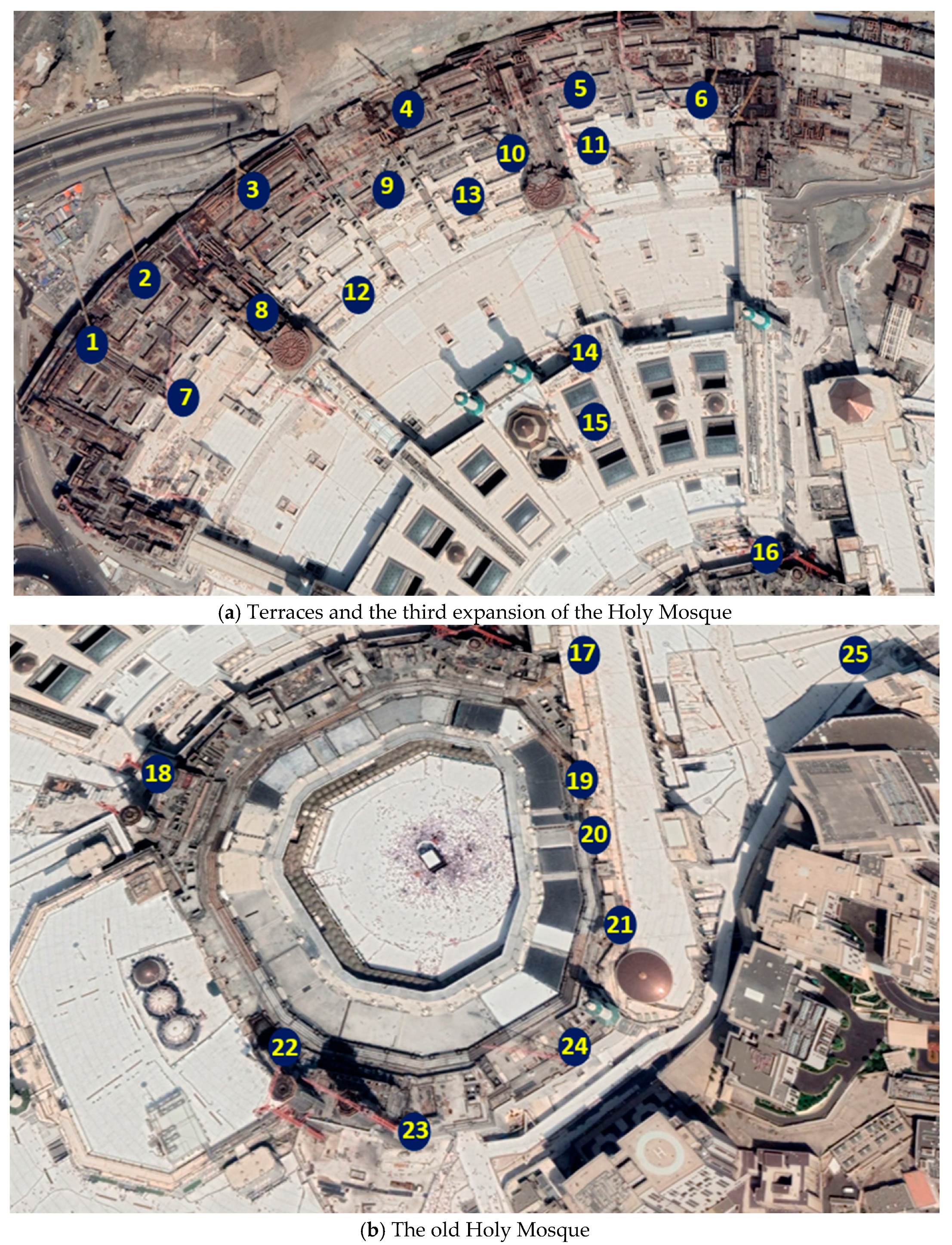
Figure 1. The selected locations of the wind gust (Google Maps on October 2022).
Buildings 13 01809 g001
Figure 2. The selected locations for the environmental study (Google Maps in October 2022).
Buildings 13 01809 g002
Figure 3. The flow chart of the current CFD study.
Buildings 13 01809 g003
Figure 4. The geometry of the studied area.
Buildings 13 01809 g004
Figure 5. The mesh of the CFD model.
Buildings 13 01809 g005
Figure 6. The boundary conditions for the model for the case of north wind direction.
Buildings 13 01809 g006
Figure 7. The velocity contours and vectors for the south wind attacking the cranes on the terraces.
Buildings 13 01809 g007
Figure 8. The velocity contours and vectors map for the third expansion of the Holy Mosque in case of the south-southwest wind 5 m above the top surface of the expansion.
Buildings 13 01809 g008
Figure 9. The velocity contours and vectors for the south-southwest wind attacking the cranes on the old Holy Mosque and the Masa’a.
Buildings 13 01809 g009
Figure 10. The ratio between the overturning moment on the crane in the Holy Mosque to that in an open area.
Buildings 13 01809 g010
Figure 11. The velocity contour and vectors map for the north-northeast wind direction (the contour plan is at the top of the Masa’a level).
Buildings 13 01809 g011
Figure 12. The wind comfort levels for all studied points.
Buildings 13 01809 g012
Figure 13. The air ventilation assessment for the selected eighteen locations inside the Holy Mosque and its piazza.
Buildings 13 01809 g013
Table 1. Summary of the boundary conditions and the solver parameters of the CFD models.
ParametersSettings
SolverPressure-based, steady
Velocity formulationAbsolute
Turbulence modelStandard k-ε
GravityNot applied
The inlet boundaryVelocity inlet
The outlet boundaryPressure outlet
The top of the modelsymmetry
The bottom of the modelwall
The other boundarysymmetry
Cell shapeTetrahedral
Disclaimer/Publisher’s Note: The statements, opinions and data contained in all publications are solely those of the individual author(s) and contributor(s) and not of MDPI and/or the editor(s). MDPI and/or the editor(s) disclaim responsibility for any injury to people or property resulting from any ideas, methods, instructions or products referred to in the content.