

The Assessment and Retrofitting of Cultural Heritage—A Case Study of a Residential Building in Glina


Abstract
1. Introduction

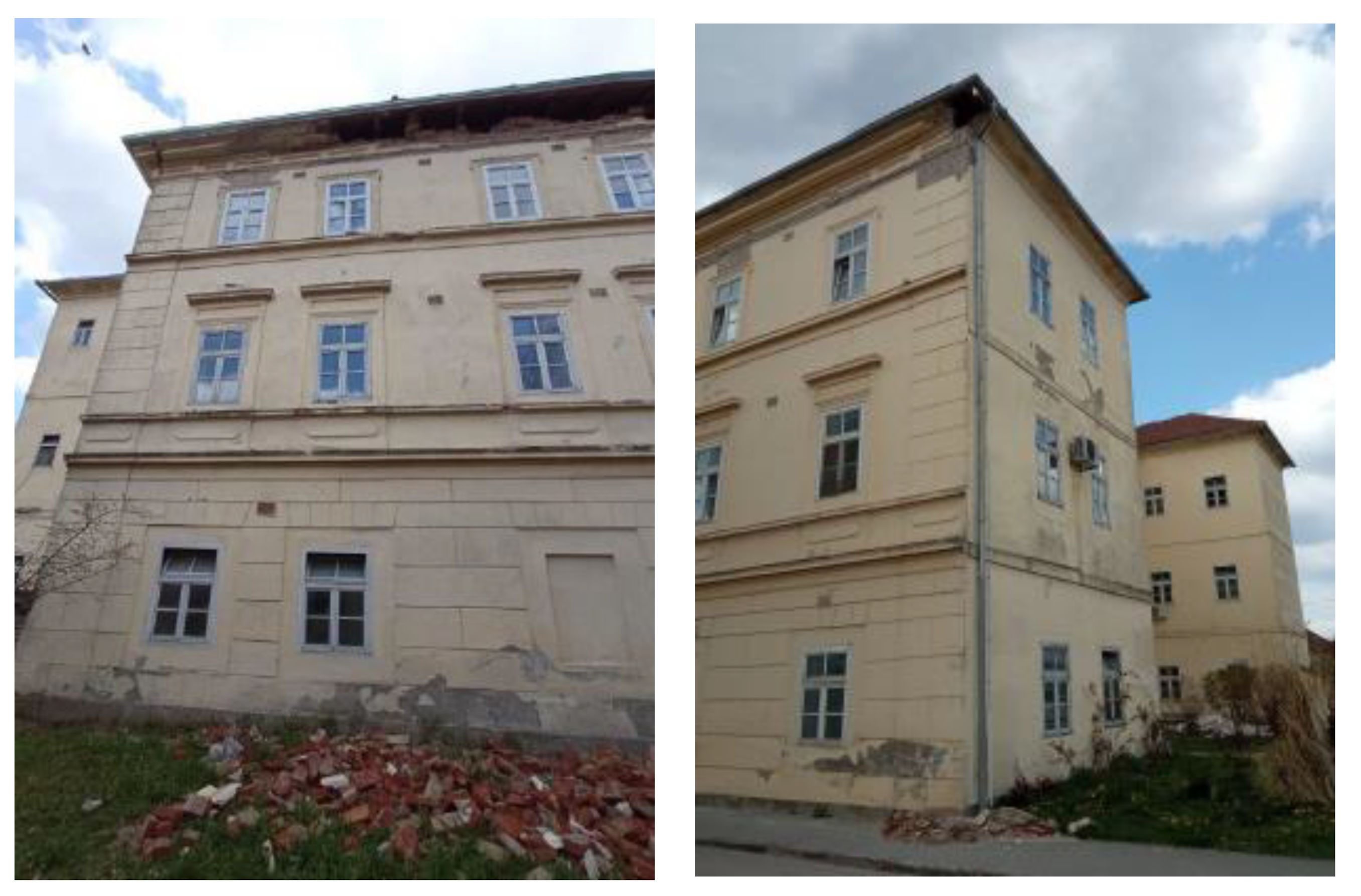
2. The Case Study
3. Methods and Materials
3.1. Assessment Procedure
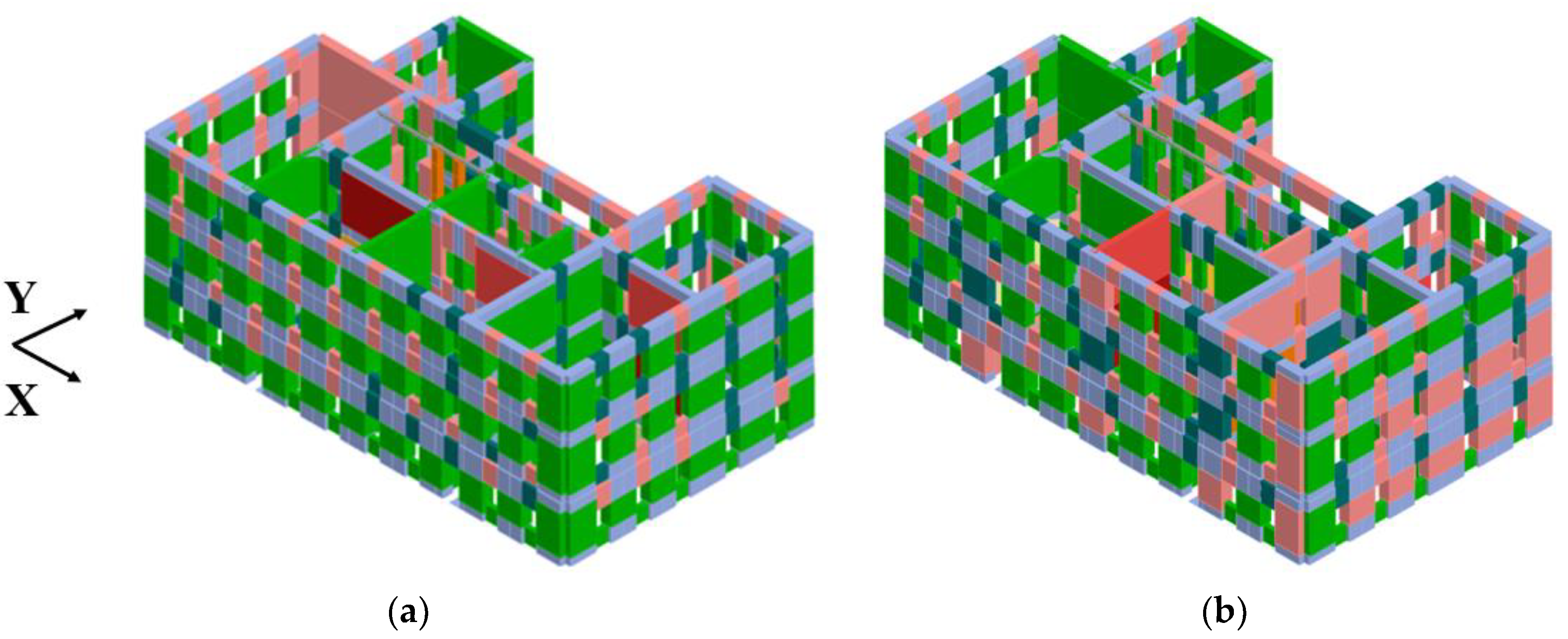
3.2. Detailed Assessment Results
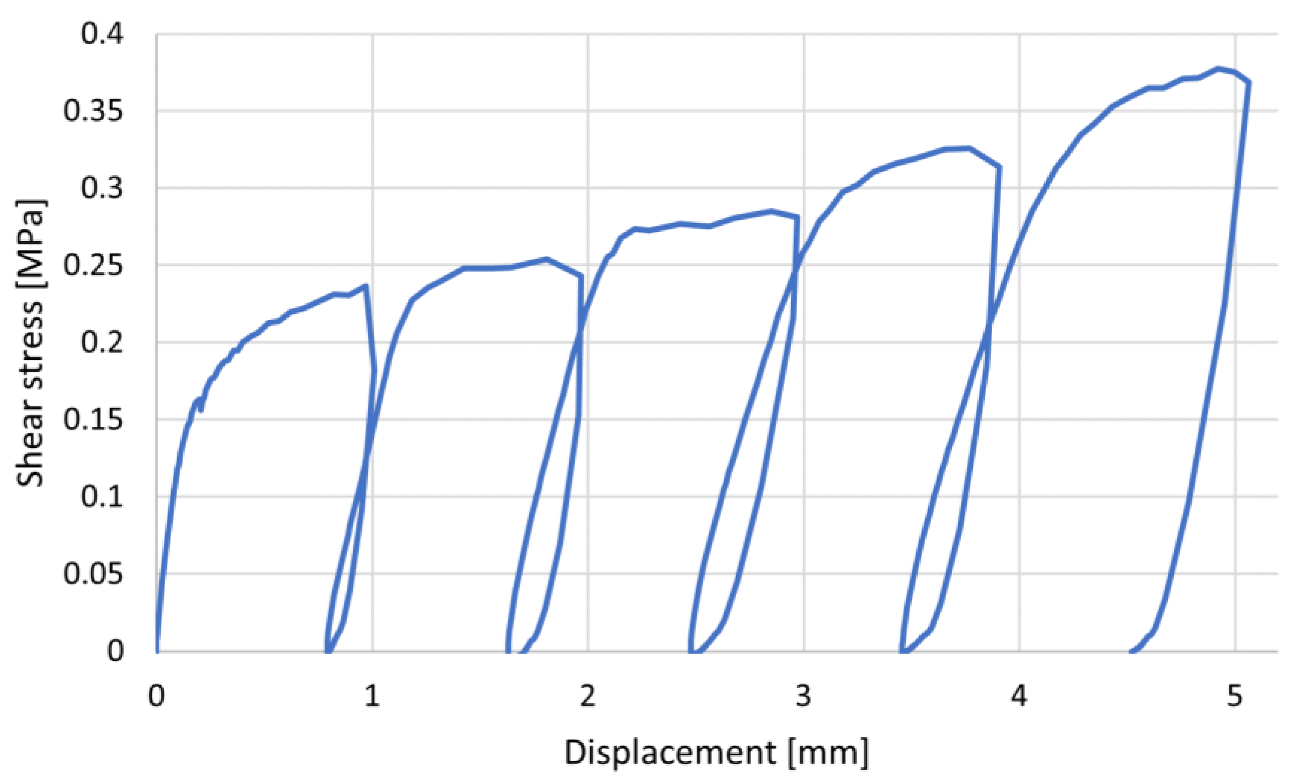
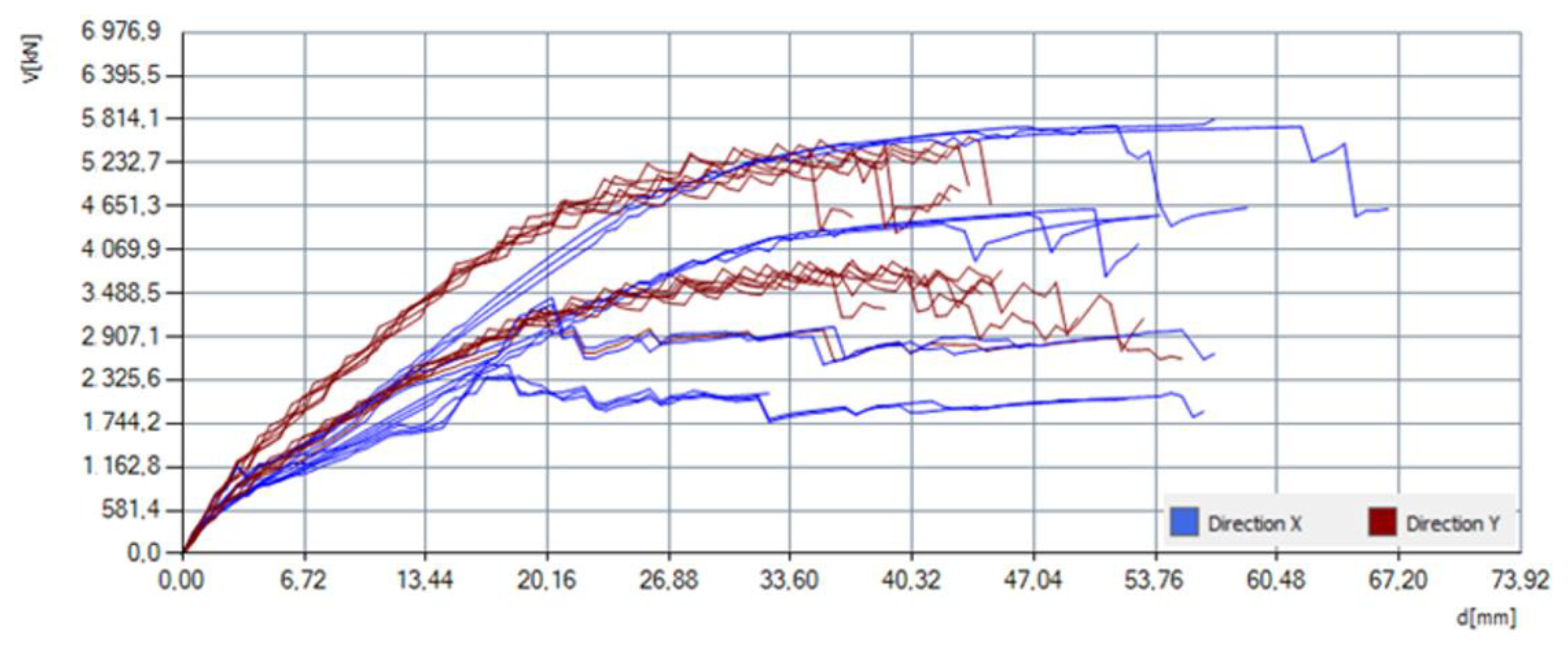
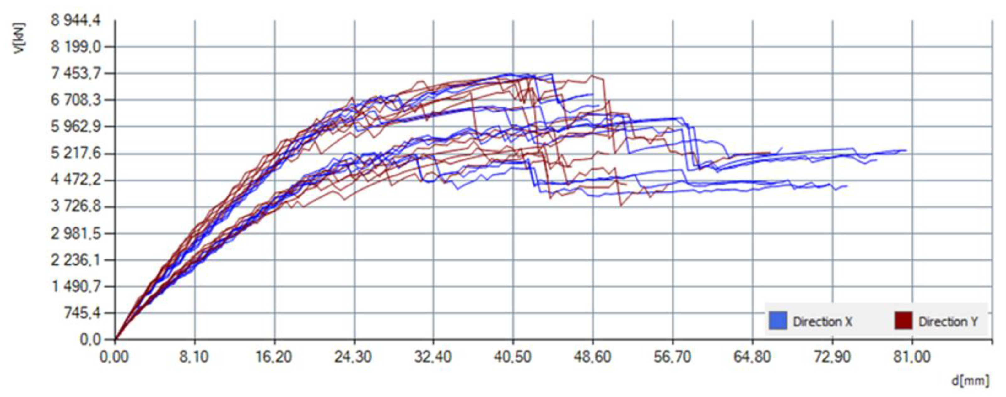
3.3. In-Situ Tests
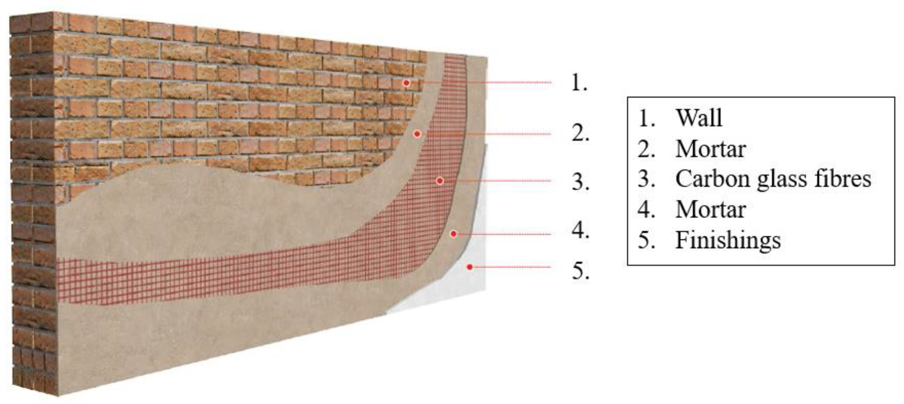
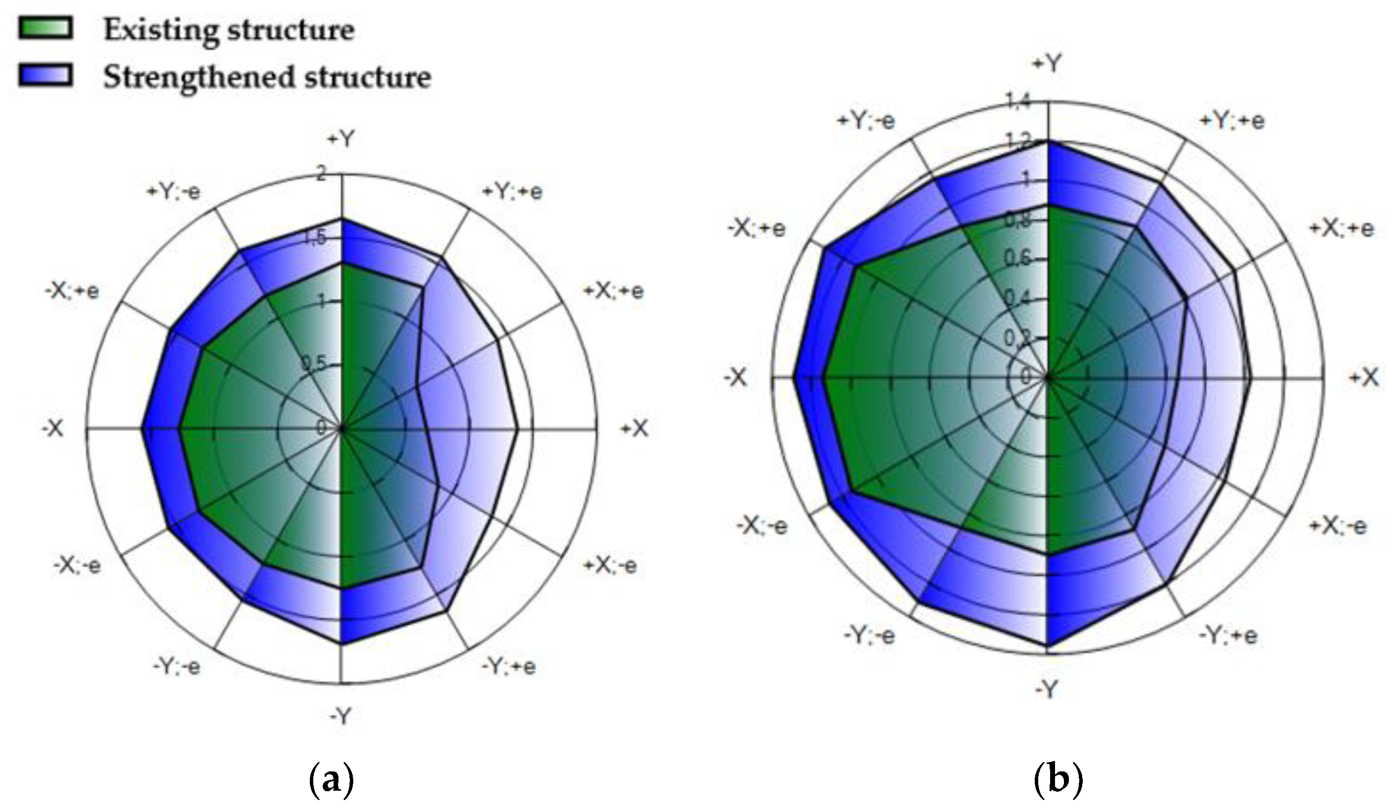
4. Structural Strengthening
5. Conclusions
Author Contributions
Funding
Data Availability Statement
Conflicts of Interest
References
- Government of the Republic of Croatia. Croatia December 2020 Earthquake Rapid Damage and Needs Assessment; The World Bank: Washington, DC, USA, 2021. [Google Scholar]
- Stepinac, M.; Lourenço, P.B.; Atalić, J.; Kišiček, T.; Uroš, M.; Baniček, M.; Novak, M.Š. Damage classification of residential buildings in historical downtown after the ML5.5 earthquake in Zagreb, Croatia in 2020. Int. J. Disaster Risk Reduct. 2021, 56, 102140. [Google Scholar] [CrossRef]
- Moretić, A.; Chieffo, N.; Stepinac, M.; Lourenço, P.B. Vulnerability Assessment of Historical Building Aggregates in Zagreb: Implementation of a Macroseismic Approach. Bull Earthq. Eng. 2022, 21, 2045–2065. [Google Scholar] [CrossRef]
- Grillanda, N.; Valente, M.; Milani, G.; Formigoni, F.; Chiozzi, A.; Tralli, A. Fast Seismic Vulnerability Evaluation of Historical Masonry Aggregates through Local Analyses: An Adaptive NURBS-based Limit Analysis Approach. In Proceedings of the 12th International Conference on Structural Analysis of Historical Constructions (SAHC), Barcelona, Spain, 16–18 September 2020; pp. 1–13. [Google Scholar]
- Valente, M. Seismic vulnerability assessment and earthquake response of slender historical masonry bell towers in South-East Lombardia. Eng. Fail. Anal. 2021, 129, 105656. [Google Scholar] [CrossRef]
- Ferretti, E.; Pascale, G. Some of the Latest Active Strengthening Techniques for Masonry Buildings: A Critical Analysis. Materials 2019, 12, 1151. [Google Scholar] [CrossRef]
- Holicky, M.; Sykora, M. Structural assessment of heritage buildings. WIT Trans. Built Environ. 2012, 123, 69–80. [Google Scholar]
- Atalić, J.; Šavor Novak, M.; Uroš, M. Seismic risk for Croatia: Overview of research activities and present assessments with guidelines for the future. Građevinar 2019, 71, 923–947. [Google Scholar]
- Department of Geophysics. Available online: http://www.pmf.unizg.hr/geof/en (accessed on 26 April 2023).
- Ožić, K.; Skejić, D.; Lukačević, I.; Stepinac, M. Value of Information Analysis for the Post-Earthquake Assessment of Existing Masonry Structures—Case Studies. Buildings 2023, 13, 144. [Google Scholar] [CrossRef]
- Der Kiureghian, A.; Ditlevsen, O. Aleatory or epistemic? Does it matter? Struct. Saf. 2009, 31, 105–112. [Google Scholar] [CrossRef]
- Sýkora, M.; Diamantidis, D.; Holický, M.; Marková, J.; Rózsás, Á. Assessment of compressive strength of historic masonry using non-destructive and destructive techniques. Constr. Build. Mater. 2018, 193, 196–210. [Google Scholar] [CrossRef]
- ARES PROJECT Assessment and Rehabilitation of Existing Structures—Development of Contemporary Methods for Masonry and Timber Structures. Available online: https://www.grad.hr/ares/ (accessed on 15 December 2021).
- Stepinac, M.; Skokandić, D.; Ožić, K.; Zidar, M.; Vajdić, M. Condition Assessment and Seismic Upgrading Strategy of RC Structures—A Case Study of a Public Institution in Croatia. Buildings 2022, 12, 1489. [Google Scholar] [CrossRef]
- Funari, M.F.; Hajjat, A.E.; Masciotta, M.G.; Oliveira, D.V.; Lourenço, P.B. A Parametric Scan-to-FEM Framework for the Digital Twin Generation of Historic Masonry Structures. Sustainability 2021, 13, 11088. [Google Scholar] [CrossRef]
- Valente, M. Seismic behavior and damage assessment of two historical fortified masonry palaces with corner towers. Eng. Fail. Anal. 2021, 134, 106003. [Google Scholar] [CrossRef]
- D’altri, A.M.; Sarhosis, V.; Milani, G.; Rots, J.; Cattari, S.; Lagomarsino, S.; Sacco, E.; Tralli, A.; Castellazzi, G.; de Miranda, S. Modeling Strategies for the Computational Analysis of Unreinforced Masonry Structures: Review and Classification. Arch. Comput. Methods Eng. 2019, 27, 1153–1185. [Google Scholar] [CrossRef]
- D’Altri, A.M.; de Miranda, S.; Castellazzi, G.; Sarhosis, V. A 3D detailed micro-model for the in-plane and out-of-plane numerical analysis of masonry panels. Comput. Struct. 2018, 206, 18–30. [Google Scholar] [CrossRef]
- Lagomarsino, S.; Penna, A.; Galasco, A.; Cattari, S. TREMURI program: An equivalent frame model for the nonlinear seismic analysis of masonry buildings. Eng. Struct. 2013, 56, 1787–1799. [Google Scholar] [CrossRef]
- Fraternali, F. A thrust network approach to the equilibrium problem of unreinforced masonry vaults via polyhedral stress functions. Mech. Res. Commun. 2010, 37, 198–204. [Google Scholar] [CrossRef]
- Bilgin, H.; Shkodrani, N.; Hysenlliu, M.; Ozmen, H.B.; Isik, E.; Harirchian, E. Damage and performance evaluation of masonry buildings constructed in 1970s during the 2019 Albania earthquakes. Eng. Fail. Anal. 2021, 131, 105824. [Google Scholar] [CrossRef]
- Uroš, M.; Šavor Novak, M.; Atalić, J.; Sigmund, Z.; Baniček, M.; Demšić, M.; Hak, S. Post-earthquake damage assessment of buildings—Procedure for conducting building inspections. J. Croat. Assoc. Civ. Eng. 2021, 72, 1089–1115. [Google Scholar]
- Kišiček, T.; Stepinac, M.; Renić, T.; Hafner, I.; Lulić, L. Strengthening of masonry walls with FRP or TRM. J. Croat. Assoc. Civ. Eng. 2020, 72, 937–953. [Google Scholar]
- Stepinac, M.; Gašparović, M. A Review of Emerging Technologies for an Assessment of Safety and Seismic Vulnerability and Damage Detection of Existing Masonry Structures. Appl. Sci. 2020, 10, 5060. [Google Scholar] [CrossRef]
- ASTM C1197-14a; Standard Test Method for in situ Measurement of Masonry Deformability Properties Using the Flatjack Method. ASTM International: West Conshohocken, PA, USA, 2014.
- RILEM Technical Committee. RILEM TC 177-MDT: Masonry Durability and on-Site Testing Recommendation MDT. D. 4: In-Situ Stress Tests Based on the Flat jack. Mater Struct. 2004, 37, 491. Available online: http://www.springerlink.com/index/10.1007/BF02481588 (accessed on 15 March 2023).
- Lulić, L.; Stepinac, M.; Bartolac, M.; Lourenço, P.B. Review of the Flat-Jack Method and Lessons from Extensive Post-Earthquake Research Campaign in Croatia. Constr. Build. Mater. 2023, 384. Available online: https://linkinghub.elsevier.com/retrieve/pii/S0950061823011200 (accessed on 5 June 2023). [CrossRef]
- Stepinac, M.; Lulić, L.; Damjanović, D.; Duvnjak, I.; Bartolac, M.; Lourenço, P.B. Experimental Evaluation of Unreinforced Brick Masonry Mechanical Properties by the Flat-Jack Method–An Extensive Campaign in Croatia. Int. J. Arch. Heritage 2023, 1–18. [Google Scholar] [CrossRef]
- Costamagna, E.; Quintero, M.S.; Bianchini, N.; Mendes, N.; Lourenço, P.B.; Su, S.; Paik, Y.M.; Min, A. Advanced non-destructive techniques for the diagnosis of historic buildings: The Loka-Hteik-Pan temple in Bagan. J. Cult. Herit. 2019, 43, 108–117. [Google Scholar] [CrossRef]
- Ortega, J.; Stepinac, M.; Lulić, L.; Nunez Garcia, M.; Saloustros, S.; Aranha, C. Correlation between Sonic Pulse Velocity and Flat-Jack Tests for the Estimation of the Elastic Properties of Unreinforced Brick Masonry: Case Studies from Croatia (Under Review in Case Studies in Construction Materials, Netherlands); 2023.
- Borri, A.; Corradi, M.; Castori, G.; De Maria, A. A method for the analysis and classification of historic masonry. Bull. Earthq. Eng. 2015, 13, 2647–2665. [Google Scholar] [CrossRef]
- Law on the Reconstruction of Earthquake-Damaged Buildings in the City of Zagreb, Krapina-Zagorje County, Zagreb County, Sisak-Moslavina County and Karlovac County (NN 21/23). Available online: https://www.zakon.hr/z/2656/Zakon-o-obnovi-zgrada-oštećenih-potresom-na-području-Grada-Zagreba%2C-Krapinsko-zagorske-županije%2C-Zagrebačke-županije%2C-Sisačko-moslavačke-županije-i-Karlovačke-županije (accessed on 27 April 2023).
- Milani, G.; Shehu, R.; Valente, M. Seismic Upgrading of a Masonry Church with FRP Composites. Mater. Sci. Forum 2016, 866, 119–123. [Google Scholar] [CrossRef]
- S.T.A. DATA, 3Muri Program 12.5.0.2. Available online: http://www.stadata.com/ (accessed on 14 December 2021).
- Fajfar, P.; Gašperšič, P. The N2 method for the seismic damage analysis of RC buildings. Earthq. Eng. Struct. Dyn. 1996, 25, 31–46. [Google Scholar] [CrossRef]
- EN 1998-1:2004; Eurocode 8: Design of Structures for Earthquake Resistance—Part 1: General Rules, Seismic Actions and Rules for Buildings. European Committee for Standardization: Brussels, Belgium, 2004.
- Gomes, M.I.; Lopes, M.; de Brito, J. Seismic resistance of earth construction in Portugal. Eng. Struct. 2010, 33, 932–941. [Google Scholar] [CrossRef]
- Lulić, L.; Ožić, K.; Kišiček, T.; Hafner, I.; Stepinac, M. Post-Earthquake Damage Assessment—Case Study of the Educational Building after the Zagreb Earthquake. Sustainability 2021, 13, 6353. [Google Scholar] [CrossRef]
- Law on the Protection and Preservation of Cultural Heritage. Available online: https://www.zakon.hr/z/340/Zakon-o-zaštiti-i-očuvanju-kulturnih-dobara (accessed on 16 February 2022).
- Yavartanoo, F.; Kang, T.H.-K. Retrofitting of unreinforced masonry structures and considerations for heritage-sensitive constructions. J. Build. Eng. 2022, 49, 103993. [Google Scholar] [CrossRef]
- Abbass, A.; Lourenço, P.B.; Oliveira, D.V. The use of natural fibers in repairing and strengthening of cultural heritage buildings. Mater. Today: Proc. 2020, 31, S321–S328. [Google Scholar] [CrossRef]
- Moretić, A.; Stepinac, M.; Lourenço, P.B. Seismic upgrading of cultural heritage—A case study using an educational building in Croatia from the historicism style. Case Stud. Constr. Mater. 2022, 17, e01183. [Google Scholar] [CrossRef]
- Low-Carbon Development Strategy of the Republic of Croatia until 2030 with a view to 2050. The Republic of Croatia, Ministry of Economy and Sustainable Development. Available online: https://mingor.gov.hr/o-ministarstvu-1065/djelokrug/uprava-za-klimatske-aktivnosti-1879/strategije-planovi-i-programi-1915/strategija-niskougljicnog-razvoja-hrvatske/1930 (accessed on 27 April 2023).
- BAUMIT. Available online: https://baumit.hr/ (accessed on 27 April 2023).
- Del Zoppo, M.; Di Ludovico, M.; Prota, A. Analysis of FRCM and CRM parameters for the in-plane shear strengthening of different URM types. Compos. Part B Eng. 2019, 171, 20–33. [Google Scholar] [CrossRef]
- Babaeidarabad, S.; De Caso, F.; Nanni, A. URM Walls Strengthened with Fabric-Reinforced Cementitious Matrix Composite Subjected to Diagonal Compression. J. Compos. Constr. 2014, 18, 242. [Google Scholar] [CrossRef]


| Floor | Mark | t (cm) | h (cm) | Km | Ka | p (bar) | σ0 (N/mm2) |
|---|---|---|---|---|---|---|---|
| Ground floor | FJ-1 | 60 | 63 | 0.759 | 0.909 | 6.4 | 0.44 |
| First floor | FJ-2 | 60 | 65 | 0.761 | 0.920 | 3.1 | 0.21 |
| Floor | Mark | E (N/mm2) |
|---|---|---|
| Ground floor | FJ-1 | 831 |
| First floor | FJ-2 | 648 |
| Floor | Mark | μ | fvo (N/mm2) |
|---|---|---|---|
| Ground floor | FJ-1 | 0.36 | 0.15 |
| First floor | FJ-2 | 0.51 | 0.22 |
| Limit State | Return Period (Year) | Peak Ground Acceleration |
|---|---|---|
| Significant damage | 475 | 0.15 g |
| Significant damage | 225 | 0.11 g |
| Damage limitation | 95 | 0.07 g |
| Material Characteristics | Value |
|---|---|
| Modulus of elasticity (N/mm2) | 740 |
| Shear modulus (N/mm2) | 300 |
| Specific weight (kN/m3) | 18 |
| Mean compressive strength (N/mm2) | 2.8 |
| Shear strength (N/mm2) | 0.18 |
| Characteristic compressive strength (N/mm2) | 2.2 |
| Limit State | Return Period (Years) | α (X Direction) | α (Y Direction) |
|---|---|---|---|
| Significant damage | 475 | 0.424 | 0.565 |
| Significant damage | 225 | 0.606 | 0.807 |
| Damage limitation | 95 | 0.819 | 0.891 |
| FRCM System | Value |
|---|---|
| Fiber thickness tf (mm) | 0.045 |
| Modulus of elasticity E (N/mm2) | 194,000 |
| Conventional strain limit (%) | 0.91 |
| Limit State | Return Period (Years) | α (X Direction) | α (Y Direction) |
|---|---|---|---|
| Significant damage | 475 | 1.099 | 0.781 |
| Significant damage | 225 | 1.451 | 1.163 |
| Damage limitation | 95 | 1.563 | 1.309 |
| Direction | Existing Structure | Strengthened Structure |
|---|---|---|
| X | 0.69 | 0.48 |
| Y | 0.58 | 0.52 |
Disclaimer/Publisher’s Note: The statements, opinions and data contained in all publications are solely those of the individual author(s) and contributor(s) and not of MDPI and/or the editor(s). MDPI and/or the editor(s) disclaim responsibility for any injury to people or property resulting from any ideas, methods, instructions or products referred to in the content. |
© 2023 by the authors. Licensee MDPI, Basel, Switzerland. This article is an open access article distributed under the terms and conditions of the Creative Commons Attribution (CC BY) license (https://creativecommons.org/licenses/by/4.0/).
Share and Cite
Ožić, K.; Markić, I.; Moretić, A.; Lulić, L. The Assessment and Retrofitting of Cultural Heritage—A Case Study of a Residential Building in Glina. Buildings 2023, 13, 1798. https://doi.org/10.3390/buildings13071798
Ožić K, Markić I, Moretić A, Lulić L. The Assessment and Retrofitting of Cultural Heritage—A Case Study of a Residential Building in Glina. Buildings. 2023; 13(7):1798. https://doi.org/10.3390/buildings13071798
Chicago/Turabian StyleOžić, Karlo, Ivan Markić, Antonela Moretić, and Luka Lulić. 2023. "The Assessment and Retrofitting of Cultural Heritage—A Case Study of a Residential Building in Glina" Buildings 13, no. 7: 1798. https://doi.org/10.3390/buildings13071798
APA StyleOžić, K., Markić, I., Moretić, A., & Lulić, L. (2023). The Assessment and Retrofitting of Cultural Heritage—A Case Study of a Residential Building in Glina. Buildings, 13(7), 1798. https://doi.org/10.3390/buildings13071798