Highlights
What are the main findings?
- -
- Exact interaction curves for the plastic resistances of Z-sections taking into account the combination of three internal forces, i.e., My,Ed, Mz,Ed and BEd, are presented.
- -
- Approximate interaction formulas for Z-section plastic resistances taking into account three internal forces, i.e., My,Ed, Mz,Ed and BEd, is presented.
Abstract
Exact interaction formulae for the plastic resistances of Z-sections under a combination of three internal forces, i.e., the bending moment about the strong axis My,Ed, bending moment about the weak axis Mz,Ed and bimoment BEd, were created and analyzed. The exact interaction curves obtained by linear programming have enabled us to create and verify the proposed approximate interaction formulae. An interaction formula that takes into account these three internal forces is missing in the Eurocodes. A large parametric study was performed for rolled Z profiles. The differences between the values of the approximate interaction formulae and exact interaction curves were analyzed and summarized. The importance of correct analyses of Z-sections in Part 3 is described and examples of incorrect calculations in many publications are collected and corrected. Several researchers have analyzed plastic resistances of I-, H-, T- and U-sections under the combination of internal forces, but nobody has studied Z-sections which are frequently used as purlins. Another motivation is to show how to calculate the properties and normal stresses in the sections without axes of symmetry, which are frequently calculated in incorrect ways, when using non-principal axes of the section.
1. Introduction
The authors performed a large parametrical study and focused on the HVH sections (H—horizontal upper flange, V—vertical web, H—horizontal bottom flange) of different shapes, e.g., I-, H-, U- and Z-sections. The partial results of this large parametrical study are already published. I- and H-sections were explored in [1], channel sections in [2] and plain Z-sections are investigated in this paper.
Light-gauge cold-formed steel members are commonly used in a range of building types as secondary steelwork and in the primary load-bearing elements in light steel frames. Light-gauge steel refers to galvanized cold-formed steel with a maximum thickness of 4.0 mm, although gauges with thicknesses from 1.2 mm to 2.0 mm are the most common applications. A lipped C-section is the most common section shape used for wall studs and floor joists with depths commonly ranging from 70 mm to 120 mm for wall studs and from 120 mm to 250 mm for floor joists. Purlins are typically made from Z or Sigma sections with depths ranging from 140 mm to 300 mm [3]. Z-sections may be with or without lips, with equal or unequal flanges. A Z-section with equal flanges is a point-symmetric section. A point-symmetric section is a section symmetrical about a point (centroid G = shear center S) [4].
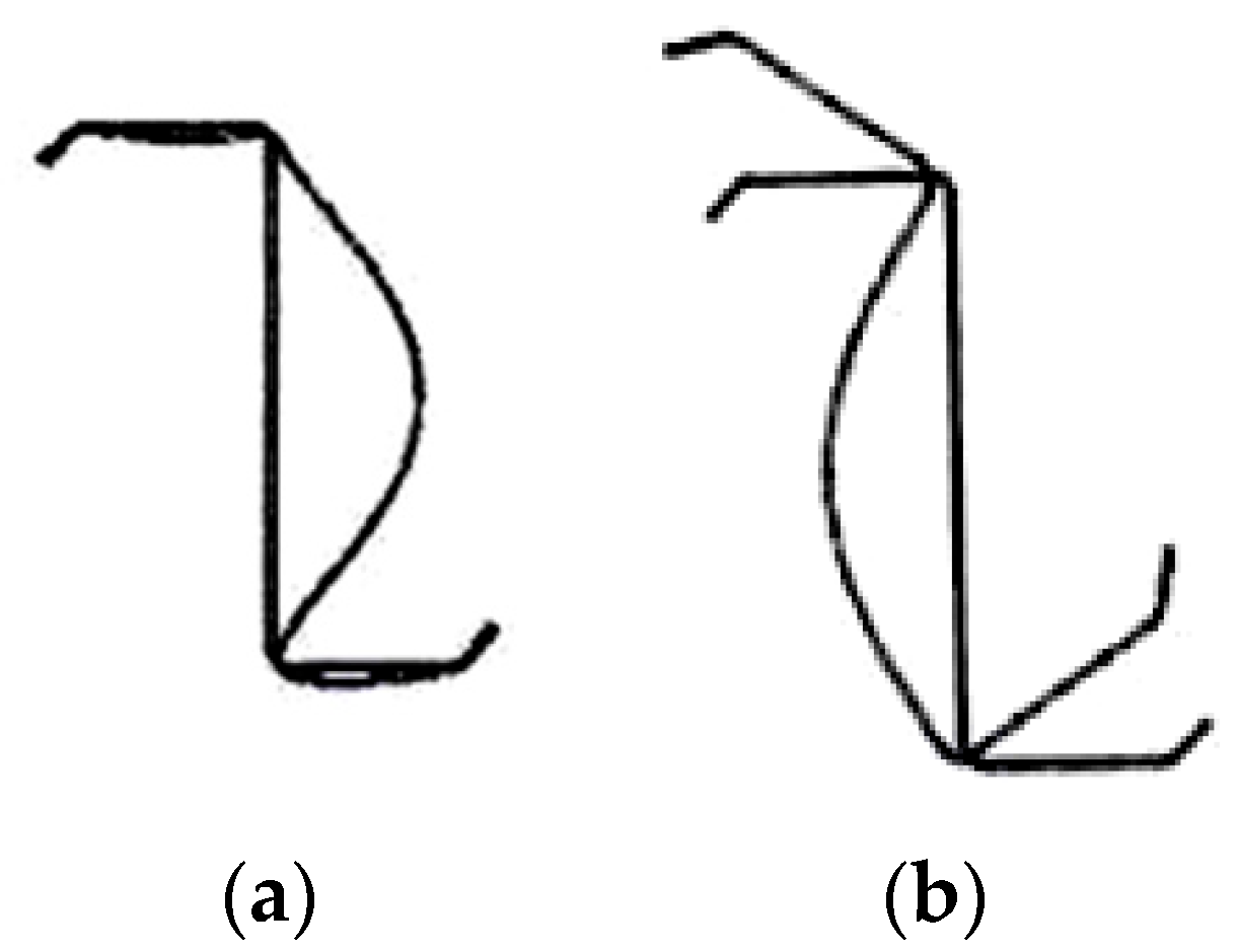
In cold-formed steel, the locally stable cross-section—consisting of non-slender plate elements—is the exception, not the rule. The limit state of distortional buckling is not often seen in hot-rolled steel sections, and is usually particular to cold-formed cross-sections. Whereas local buckling is limited to the deformation of individual plate elements, distortional buckling involves the distortion of the cold-formed cross-section shape [5]. Local buckling and distortional buckling of a lipped Z-section under compression may be seen in Figure 1.

Figure 1.
Lipped Z-section: (a) local buckling in compression; (b) distortion buckling in compression.
Class 4 cross-sections are those where local buckling will occur before the attainment of yield stress in one or more parts of the cross-section. Z-sections in Figure 2 of Class 4 are generally designed following the recommendations of a recognized code of practice. The appropriate document for light-gauge steel design in Europe is Eurocode part EN 1993-1-3 [6]. It permits two alternative design routes: (a) design by calculation, and (b) design by testing. When testing is undertaken, such as that of purlins and cladding rails, the design data are usually tabulated in the form of load span tables.
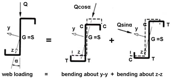
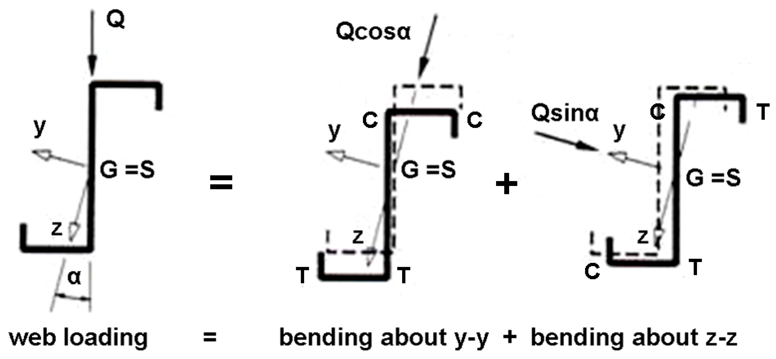
Figure 2.
Biaxial bending of lipped Z-section.
The elastic limit state may be achieved for a Class 3 cross-section. Class 3 cross-sections are those where the stress in the extreme compression fiber of the steel member, assuming an elastic distribution of stresses, can reach the yield strength, but local buckling is liable to prevent development of the plastic moment of resistance [7].
The presented paper is focused on the point-symmetric Z-sections without lips of Class 1 and 2. Class 1 cross-sections are those which can form a plastic hinge with the rotation capacity required from plastic analysis without reduction of the resistance. Class 2 cross-sections are those which can develop their plastic moment of resistance, but have limited rotation capacity because of local buckling [7].
The large parametrical study of I-sections, H-sections [1] and U-sections [2], together with the presented results which are valid for Z-sections, enable us to compare the influence of the shapes of HVH sections on plastic resistances of Class 1 and 2 sections under combinations of three internal forces: bending moments My,Ed and Mz,Ed and bimoment BEd.
Z-sections of Class 1 and 2 are used rarely in practice. This is the reason why only a few researchers have investigated plastic resistance of Z-sections.
The analysis in this paper is based on the following sign convention. Positive internal forces cause tension stresses as follows: My,Ed in the bottom section fibers, Mz,Ed, in the right section fibers, NEd, and bimoment BEd in the web of the Z-section.
Z-sections are made from hot-rolled steel, aluminum alloys, GRP composites or FRP composites. Aluminum Z-sections are commonly used in general engineering and repair work. The Z profiles are manufactured from extruded sections of 6082-T6. GRP Z profiles are used as a joint element in multiple applications, such as false ceilings, panel structures, pergolas, skylights and GRP structures [8]. The lightness of this material makes it ideal for lightweight structures. In this paper, Z-sections made of hot-rolled steel are investigated.
1.1. Overview of the Former Investigations
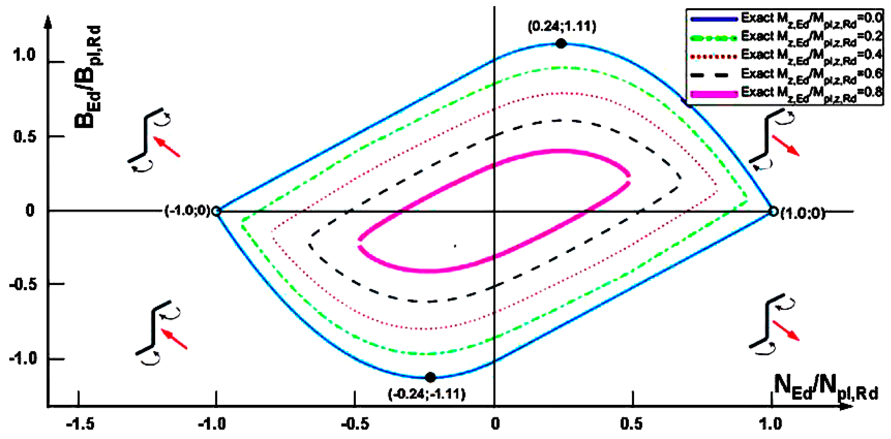
In reference [9], a plastic theory describing the ultimate behavior of open section members is developed. The accompanying method of analysis allows for the determination of an ultimate generalized load-interaction diagram. The theories in reference [9] are original in describing for the first time elasto-plastic and plastic variable warping torsion behaviors including bimoment–warping curvature relationships. In reference [9], I-sections, channels and Z-sections are investigated. For a Z-section, the axial load–bimoment of plastic resistance is determined in Figure 3. Both bending moments are kept as zero. For Z4 × 8.2, the ultimate axial load–bimoment interaction diagram was drawn. The diagram exhibits diametral symmetry. The interaction curve is characterized by two types of stress distribution.

Figure 3.
Resistances of Z200 section under the combination of and . Four small schemes indicate sign conventions of and . Diagram will be the same if the sign of will be changed. In fact bimoments besides bending moments in flanges produce an axial force in the flanges that is in equilibrium with the axial force in web.
In the first type of stress distribution, the web is subjected to uniform tensile or compression yield stresses and the flanges to both. Considering the positive bimoment region only, the flange length under tensile yield stress increases as the axial load on the section increases from the maximum compressive value until the flanges are completely in tension. Meanwhile, the web is under compressive yield stress.
In the second type of stress distribution characterizing this interaction diagram, the flanges are subjected to tensile or compression yield stresses and the web stresses vary from a uniform compressive yield value to a tensile yield value or vice versa. Considering the positive bimoment region, the flanges are under tensile yield stress and the web stress varies from compression to tension as the axial load increases to the ultimate tensile value.
The interaction curve clearly indicates that the maximum bimoment is developed in the presence of a small axial load. Therefore, the maximum warping torsional moment this section can sustain is developed also in the presence of a small axial load.
The theory developed and the method of analysis presented in reference [9] allows for the determination of plastic resistance diagrams for axial load, bending moments and bimoments acting on any thin-walled open section members.
In reference [10], a procedure was described for deriving the yield surface equations for thin-walled open cross-sections with an enforced center of rotation. Equations have been derived for the specific case of a Z-section. These equations have been shown to satisfy the uniqueness theorem of plastic analysis, thereby furnishing the correct yield surface. The applications are stiffened cylinders. Stiffeners on such cylinders are usually thin-walled open cross-sections, such as flat bars or T-, L- or Z-sections.
The study in reference [10] investigates the effect of eccentric compressive load on the stability, critical states and load-carrying capacity of thin-walled carbon-fiber-reinforced plastic composite Z-profiles. Short thin-walled columns made of CFRP [11] composite material fabricated by the autoclave technique are examined. In experimental tests, the thin-walled structures were compressed until their load-carrying capacity was lost.
Kindmann and Frickel presented in reference [12] an original method called the Partial Internal Forces Method (Teilschnittgrößenverfahren = TSV). The method enables one to calculate the plastic resistance of the metal member cross-section consisting of two or three elements, e.g., L-, T-, I-, U- and Z-sections, which may be loaded with up to eight internal forces: N, My, Mz, B, Vz, Vy, Tw and Tt. Designers may use a free computer program [13] based on the PIF (TSV) method.
Similar possibilities are also offered by DLUBAL’s computer program [14] based on the simplex method and the software developed by the authors [15,16]. Agüero’s software has been compared for I-sections, channel sections and Z-sections with references [13,14], while, for angle sections, it has been compared with the studies by Martincek [17] and Vayas [18], obtaining the same results.
The properties of Z-sections may be found in the standards [19,20]. In the present paper, Z-sections made of hot-rolled steel [19] are investigated.
Some key properties for the Z-section and channel section were published by Baláž [21,22,23]. The following table is a summary of the main results presented for Z-sections.
1.2. Calculation of the Factor ξ
ξ is the factor by which internal forces and moments must be multiplied to reach the plastic resistances of the cross-sections. In order to find the factor ξ {ξNEd, ξMy,Ed, ξMz,Ed, ξBEd}, the lower bound theorem can be used.
The static or lower bound theorem means that if the equilibrium and plastic condition are verified, then the factor ξ is equal to or less than the plastic load combination.
This lower bound procedure was applied by two methods that can be programmed as follows:
- Method A, which divides the section into elements. The unknowns are the stresses in each element;
- Method B, which divides the section into three parts (two flanges and the web). In each part, the unknowns are the axial force and the bending moment about the strong axis.
1.2.1. Method A (According to Osterrieder et al. [24])
In Method A, the factor ξ and the associated normal stresses σ are calculated. It consists of several steps.
Step 1. Dividing section into elements.
Step 2. Considering linear constraints with Equations (1)–(5).
Limitation of the normal stresses:
Equilibrium equations:
Step 3. Calculation of the maximum value of the factor ξ:
The problem can be solved by the linear programming.
Method A can be generalized as suggested by Osterrieder et al. [24] by taking into account the shear forces Vz,Ed and Vy,Ed, warping Tw,Ed and St. Venant torsional moments Tt,Ed, which cause the shear stresses τxyi and τxzi in each element. Then, the nonlinear constraint can be expressed by von Mises criterion (this criterion can be also linearized [24]).
1.2.2. Method B (Kindmann and Frickel [12])
The Z-section consists of three parts: top flange—index Tfl, bottom flange—index Bfl and web—index w. In Method B, the following quantities are calculated: factor ξ to accomplish plastic resistance, axial forces N {; ; } and bending moments M in each Z-section part {; ; }.
The steps of the Method B are as follows.
Step 1. Dividing section into three parts.
Calculation of the axial and bending resistances of all three parts:
Step 2. Considering constraints.
Nonlinear interaction formula containing the plastic resistances of the top flange:
Nonlinear interaction formula containing the plastic resistances of the bottom flange:
Nonlinear interaction formula containing the plastic resistances of the web:
Equilibrium equations:
where
A is the area of the section,
Afl is the area of the flange,
Aw is the area of the web.
Step 3. Calculation of the maximum value of the factor ξ:
1.3. Research Significance
The steps of Method A and Method B are described in detail. They enable us to obtain the exact interaction formulae.
For the beams with Z-sections, the interaction formulae for the calculation of the plastic resistances of cross-sections under the bending moment about the strong axis, My,Ed, the bending moment about weak axis, Mz,Ed, and the bimoment BEd are proposed. They are derived and presented in Section 3.
2. Interaction Formulae of the Authors’ Proposal (Approximate Curves)
At this point, an approximate interaction model for the section under study is presented. The bending moments about the strong and weak axes and the bimoment are considered, assuming that the axial force is zero. Let us define the dimensionless design bending moments and bimoment as
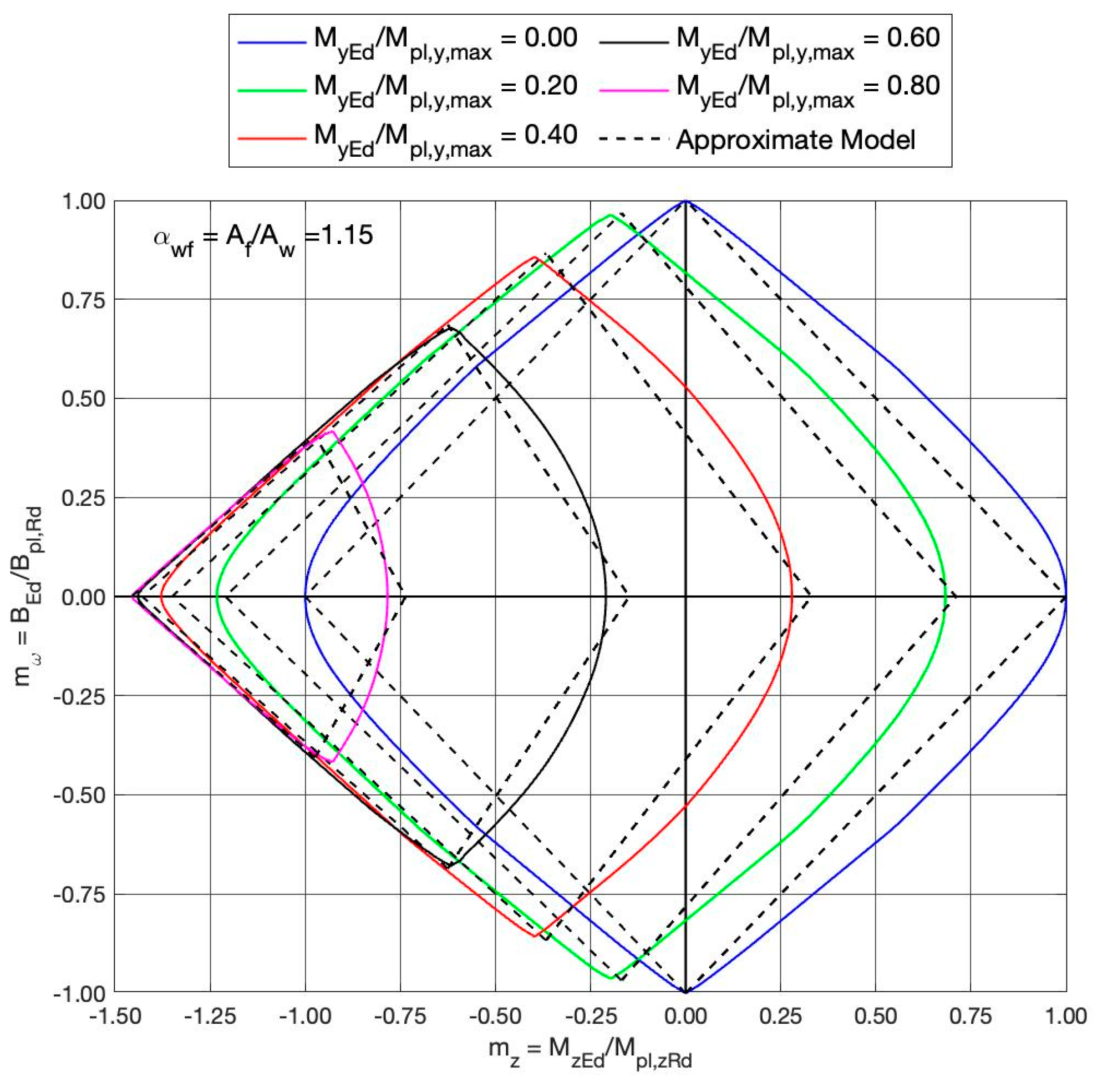
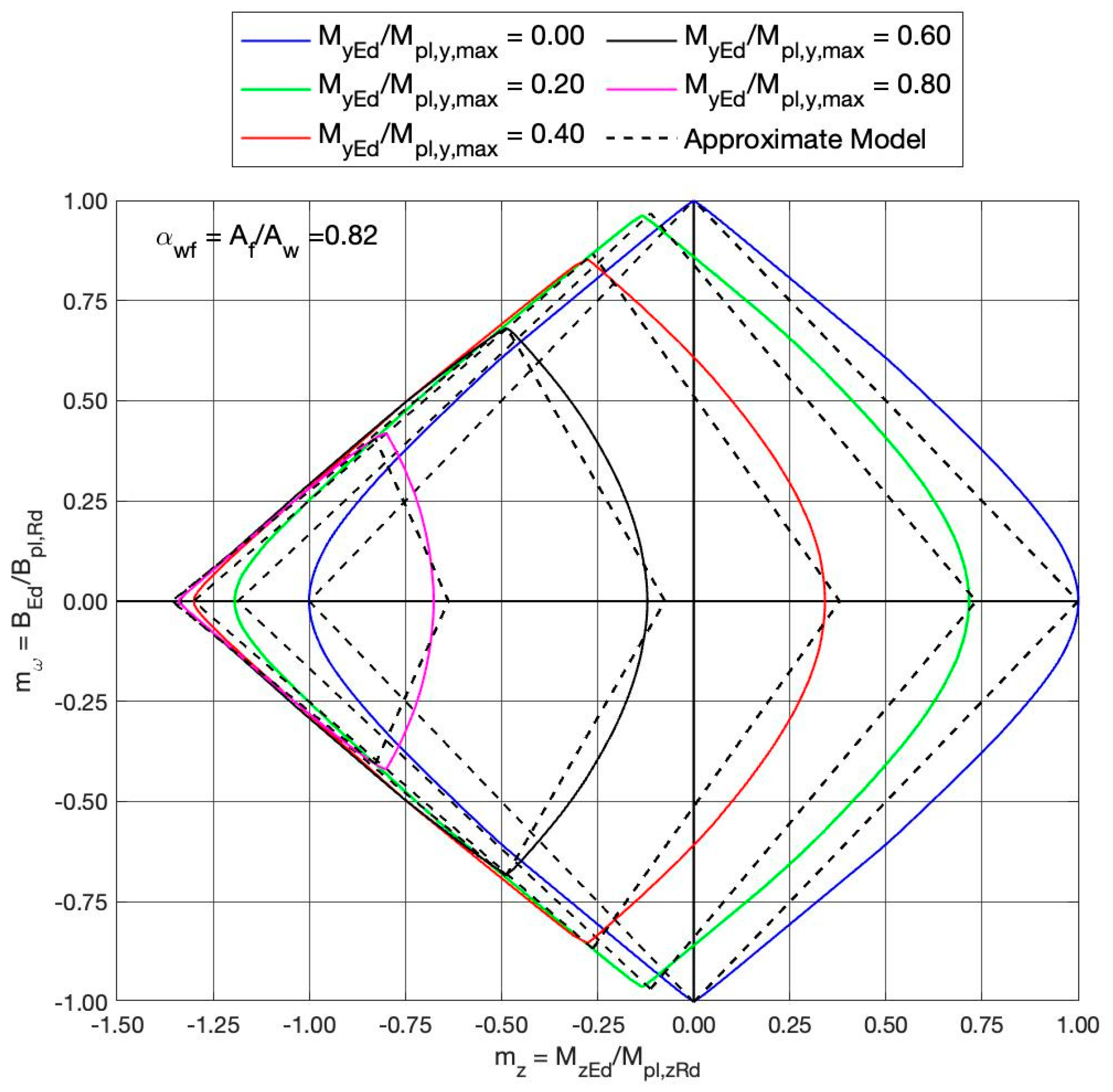
Let us consider interaction diagrams in the axes , assuming as a parameter, and let be the flanges-to-web-area ratio. Considering these axes, simulations using the exact formulation results in the interaction diagrams that are symmetrical with respect to the horizontal line . These diagrams are formed by two curves with the approximate shapes of hyperbolae. In the present work, we propose an interaction diagram formed by two families of straight lines. The numerical model presented above has been used to obtain the characteristic points of the diagram: the maximum and minimum values of the bimoment (intersection of the two curves) and the maximum and minimum values of the bending moment about the z-axis. After a statistical adjustment of these points as a function of the bending moment about the y-axis and the flange-web relationship , the following approximate interaction diagram has been obtained, consisting of the intersection of the following two regions:
where the two functions and are defined as
For each value of the -axis bending moments, the region defined by Equations (17) and (18) is limited by four straight lines forming a rhombus-type figure. The contour of Equation (17) is defined by the two left boundaries of such region, meanwhile Equation (18) defines the right ones. The proposed diagram has been derived respecting the symmetry of the problem in reference to the bending moments about the -axis. The above expressions are valid for the range of the bending moment about the -axis:
Moreover, the validity range of the cross-section parameter is
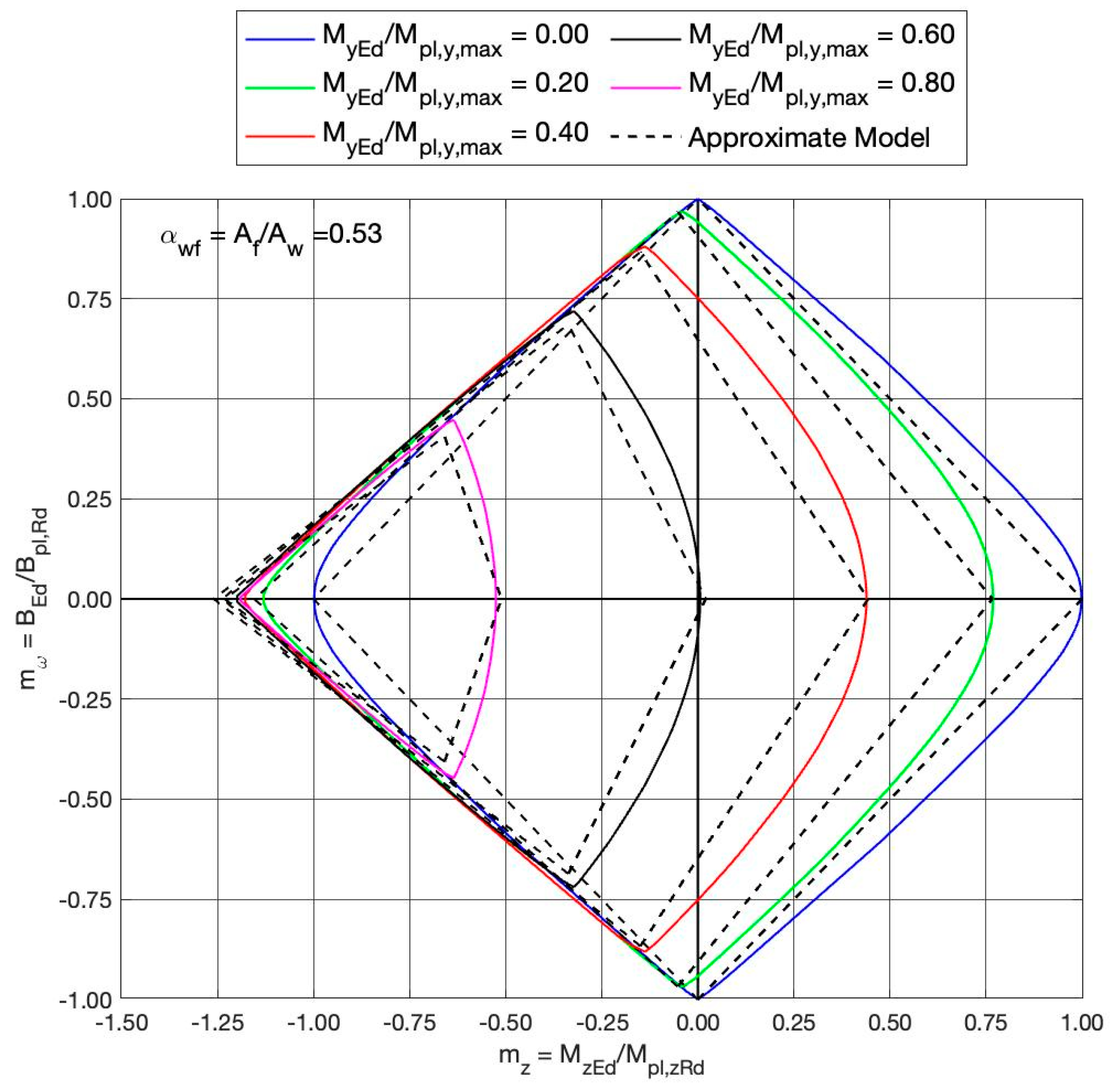
In Figure 4, Figure 5 and Figure 6, the exact and proposed diagrams are shown for three different sections, . Five different cases have been evaluated, leading to five interaction diagrams.
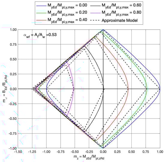
Figure 4.
Exact (solid curves) and proposed approximate (dashed lines) interaction diagrams. Results for a Z—type section with the flange-to-web-area ratio and for the concomitant y—axis bending moment of .

Figure 5.
Exact (solid curves) and proposed approximate (dashed lines) interaction diagrams. Results for a Z—type section with the flange-to-web-area ratio and for the concomitant y—axis bending moment of .
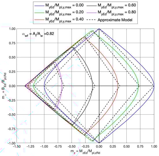
Figure 6.
Exact (solid curves) and proposed approximate (dashed lines) interaction diagrams. Results for a Z—type section with the flange-to-web-area ratio and for the concomitant y—axis bending moment of .
As observed, the interaction region moves leftwards as covers the range from up to . If, on the other side, in the range , then the different diagrams move rightwards. In the limit cases , the interaction diagrams degenerate into the two points
Let us illustrate the application of the proposed method with a numerical example. Consider the Z-shaped section with the following geometrical properties: mm, mm, mm and mm. The main plastic properties of the section can be obtained using formulas in Table 1.
leading to the following sectional relationships between the maximum and concomitants plastic moments:

Table 1.
Properties of Z-section. Calculation model is based on midline with thicknesses.
The flanges-to-web-area ratio in this case is , which corresponds to the numerical results of Figure 4. The proposed interaction diagram is formed by the intersection of two half-space regions defined by in Equations (17) and (18). The reference axes in Figure 4 are (horizonal axis) and (vertical axis). Equations (17) and (18) can be rewritten in a more compact form as
where the coefficients and are given by
For each value of , we obtain one interaction diagram. In particular, Equation (22) represents the two left sides of each rhombus, while Equation (23) reproduces the right ones. In particular, the values of these coefficients have been listed in Table 2 together with the output values of the functions and given by Equation (19).
Table 2.
Numerical values for diagrams in Figure 4, bounded by straight lines and .
Thus, for instance, the red curve in Figure 4 reproduces the exact interaction diagram for an external -axis moment . Entering in Table 2 (column for , we obtain the coefficients A, B, C and D and the interaction diagram is the region enclosed by the straight lines provided by
The approximate interaction diagrams are plotted as dashed black lines in Figure 4.
Figure 4, Figure 5 and Figure 6 show that results based on the approximate interaction formulae differ in a negligible way from the exact results based on the method described above, being on the safe side. The diagrams in the figures are symmetric (a) to the horizontal axis BEd = 0 for all combinations with My,Ed and Mz,Ed, and (b) to the vertical axis Mz,Ed = 0 only for My,Ed = 0.
3. Importance of Z-Section Analysis
Analysis of plastic resistances of Z-sections under a combination of various internal forces is presented. The formulae provided in Table 1 and used in this paper are based on the section model defined by a midline with thicknesses. However, these “approximate” formulae provide results which differ in a negligible way from the “exact” values based on the exact shape of a Z-section. Elastic cross-sectional properties of hot-rolled Z-sections may be taken also from the German standard DIN 1027:2004-04 [19]. It is shown that some values in DIN 1027:2004-04 [19] are incorrect (Table 3).
Table 3.
Elastic section moduli and of Z-sections in cm3: (a) the incorrect values according to DIN 1027:2004-04 [2]; (b) the values calculated with the formulae from Table 1.
Moreover, DIN 1027:2004-04 [19] offers only bending elastic properties. Some commercial computer programs calculate elastic and plastic cross-sectional characteristics and resistances to both y-y and z-z axes and also to the principal u-u and v-v axes (Figure 7). Unfortunately, some of their results are incorrect. Also, in several publications, the values of the elastic section moduli and (sometimes denoted as and ) are incorrect, e.g., in Table 10.8 on page 258 in [25], on page 785 in [26], on page 8.99 in [27], on pages 72, 74, 76, 78, 80, 82 and 84 in [28], and on pages V-29 and V-30 in [29]. The incorrect way of calculating may be found in [30]. The incorrect and values of Z-section properties are also in the tables of their producers [31,32,33,34,35,36,37,38,39,40,41,42]. The values of the elastic section moduli and given in [25,26,27,28,29,30,31,32,33,34,35,36,37,38,39,40,41,42] have no use and may lead to the incorrect values of the elastic bending moment resistances and on the unsafe side, as is the case in the example No.4 on page IV-20 in [30]. Table 3 shows big differences between the correct and incorrect values of and .
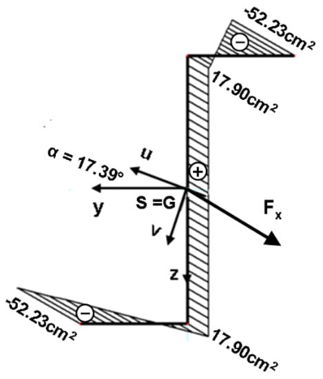
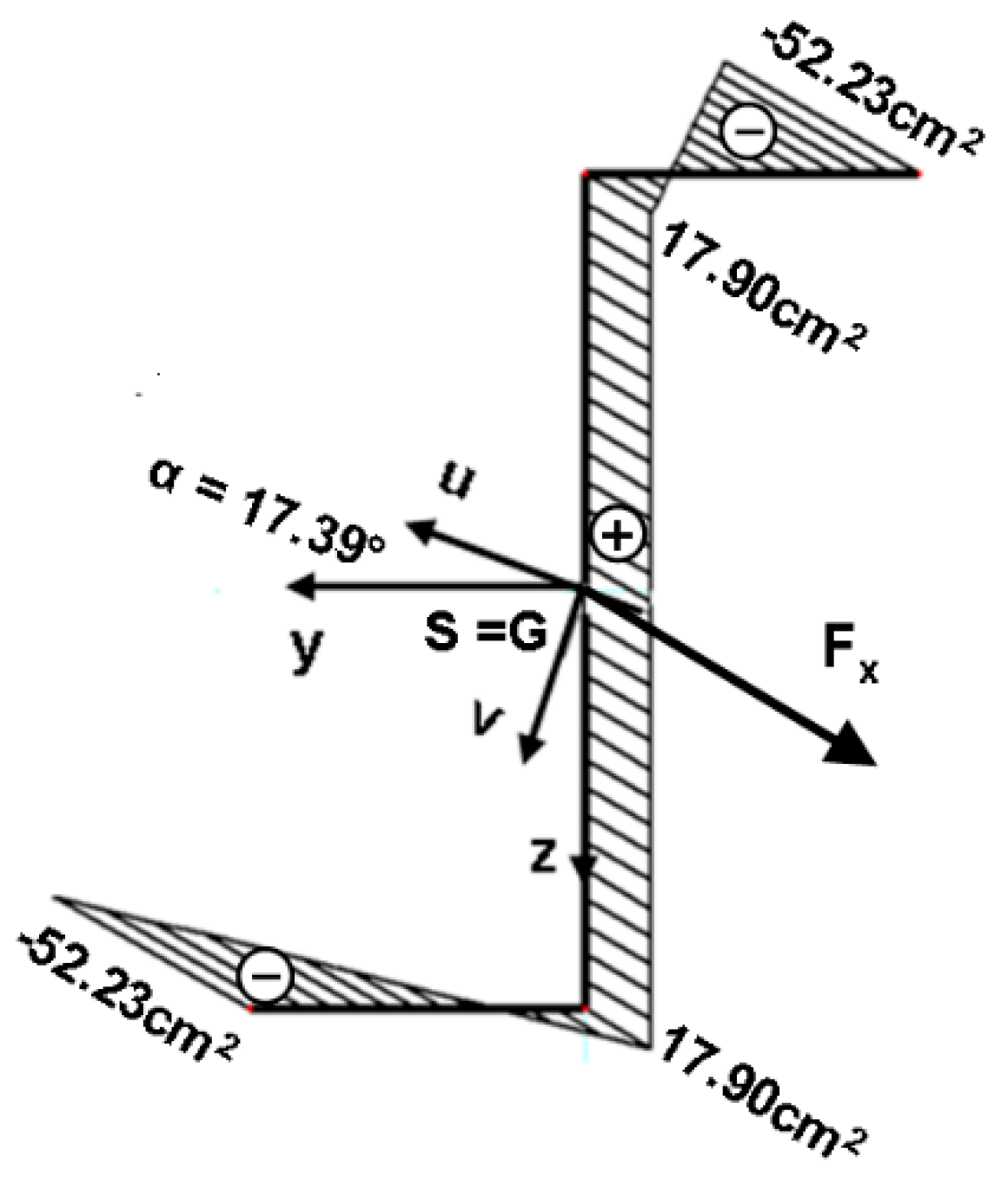
Figure 7.
Distribution of warping function for the section Z200-DIN 1027.
The present paper offers for Z-sections the correct formulae for calculation of the values of a) the bending and torsional cross-sectional elastic and plastic characteristics and b) the bending and torsional elastic and plastic resistances, including their maximum values which may be achieved with combination of other internal forces. Numerical examples show details of calculations and interaction diagrams, as well. The interaction diagram in Figure 3 was calculated with the author’s own computer program THINWALLRES [15], and it represents just a small part of a large parametrical study which will be published in another paper.
Table 4.
Numerical example No.1. Properties of hot-rolled section Z200—DIN 1027 [19]. Relative dimensionless properties and physical properties using thin-walled-hypothesis-based analytical expressions from Table 1.
Roll-formed Z-sections [43] may be seen in various steel constructions such as commercial buildings, large storage silos, mezzanine flooring, racking, residential garage doors, fencing, etc. The presented procedure will be useful for designers in practice, authors of computer programs and participants in educational processes.
4. Conclusions
The authors performed a large parametric study and focused on the HVH sections (H—horizontal upper flange, V—vertical web, H—horizontal bottom flange) of different shapes, e.g., I-, H-, U- and Z-sections. The partial results of the large parametrical study were already published. I- and H-sections were investigated in references [1,21,44], channel sections in references [2,23] and Z-sections in reference [22] as well as in this paper.
The proposal is given to show how to fit the curves for Mz, My and B in an approximate way.
The need to have interaction curves in order to calculate the plastic resistances of the Z-section under combinations of the internal forces My, Mz and B is justified in the introduction. The exact curves are obtained for different values of My, showing the interaction between Mz and B.
Future work should study the plastic resistances of other types of cross-section shapes by taking into account first the four internal forces, i.e., NEd, My,Ed, Mz,Ed and BEd, causing normal stresses, and later all eight internal forces causing normal and shear stresses.
The importance of correct Z-section analysis is justified in Part 3. In this part, there are tables containing two numerical examples showing that some cross-sectional characteristics given in DIN 1027:2004-04 [19] are incorrect. Warning is given related to several publications [25,26,27,28,29,30,31,32,33,34,35,36,37,38,39,40,41,42], including the standard [29], which offer cross-sectional characteristics and may lead to the calculation of Z cross-section resistances on the dangerous side.
The results presented in this paper are needed to design proper Z-sections in regard to elastic and plastic behaviors.
Author Contributions
Conceptualization, A.A., I.B., Y.K. and M.L.; methodology, A.A., I.B., Y.K. and M.L.; software, A.A.; validation, A.A.; writing—original draft, A.A., I.B., Y.K. and M.L.; writing—review and editing, A.A. All authors have read and agreed to the published version of the manuscript.
Funding
This research was supported by the Grant CIGE/2021/141 funded by Generalitat Valenciana as the Emerging Research Groups Grants.
Data Availability Statement
Not applicable.
Acknowledgments
A.A. and M.L. are grateful for the partial support and funding from Grant CIGE/2021/141 funded by Generalitat Valenciana as the Emerging Research Groups Grants.
Conflicts of Interest
The authors declare no conflict of interest.
Nomenclature: (Alphabetically)
| BEd | design value of the bimoment |
| Bpl,Rd | design value of the plastic bimoment resistance |
| b | width of a cross-section |
| fy | yield stress |
| h | depth of a cross-section |
| hw | web depth |
| MBfl,z,Ed | design value of the bending moment of the bottom flange about the z-axis |
| MBfl,z,Rd | design value of the plastic bending moment resistance of the bottom flange about the z-axis |
| Mfl,z,Rd | design value of the plastic bending moment resistance of the flange about the z-axis |
| Mpl,y,Rd, Mpl,Rd | design value of the plastic moment resistance about the y-axis |
| Mpl,z,Rd | design value of the plastic moment resistance about the z-axis |
| MTfl,z,Ed | design value of the bending moment of the top flange about the z-axis |
| MTfl,z,Rd | design value of the plastic bending moment resistance of the top flange about the z-axis |
| Mw,pl,y,Rd | design value of the plastic moment resistance of the web about the y-axis |
| Mw,y,Ed | design value of the bending moment of the web about the y-axis |
| Mw,y,Rd | design value of the plastic bending moment resistance of the web about the y-axis |
| My,Ed | design value of the bending moment about the y-axis |
| Mz,Ed | design value of the bending moment about the z-axis |
| NBfl,Ed | design value of the axial force of the bottom flange |
| NBfl,Rd | design value of the plastic axial force resistance of the bottom flange |
| NTfl,Ed | design value of the axial force of the top flange |
| NTfl,Rd | design value of the plastic axial force resistance of the top flange |
| Nw,Ed | design value of the axial force of the web |
| Nw,Rd | design value of the plastic axial force resistance of the web |
| Tt,Ed | design value of internal St. Venant torsional moment |
| Tw,Ed | design value of internal warping torsional moment |
| tf | flange thickness |
| tw | web thickness |
| Vy,Ed | design value of the shear force in direction of the y-axis |
| Vz,Ed | design value of the shear force in direction of the z-axis |
| y, z | section coordinates along the y- and z-axes |
| γM0 | partial safety factor for the resistance of cross-section whatever the class is |
| σ | normal stress |
| τ | shear stress |
| ω | warping function |
References
- Agüero, A.; Baláž, I.; Koleková, Y.; Moroczová, L. New interaction formula for the plastic resistance of I- and H-sections under combinations of bending moments My,Ed, Mz,Ed and bimoment BEd. Structures 2021, 29, 577–585. [Google Scholar] [CrossRef]
- Agüero, A.; Baláž, I.; Koleková, Y.; Lázaro, M. New interaction formula for plastic resistance of channel sections under combinations of bending moments My, Ed, Mz, Ed and bimoment BEd. Structures 2022, 44, 594–602. [Google Scholar] [CrossRef]
- Davison, B.; Owens, G.W. (Eds.) Steel Designers Manual, 7th ed.; SCI, Wiley Blackwell: Chichester, UK, 2016. [Google Scholar]
- Yu, W.-W. Cold-Formed Steel Design, 2nd ed.; John Wiley & Sons. Inc.: New York, NY, USA, 1991. [Google Scholar]
- Sputo, T.; Turner, J.L. Bracing Cold-Formed Structures. A Design Manual; ASCE, SEI: Reston, VA, USA, 2006. [Google Scholar]
- CEN. EN 1993-1-3:2006 and Corrigendum AC (2009) and Amendment A1; Eurocode 3: Design of Steel structures. Part 1-3: General Rules—Supplementary Rules for Cold-Formed Members and Sheeting; CEN: Brussels, Belgium, 2015. [Google Scholar]
- CEN. EN 1993-1-1:2005 and Corrigendum AC (2006) and Corrigendum AC (2009) and Amendment A1; Eurocode 3: Design of Steel Structures. Part 1.1: General Rules and Rules for Buildings; CEN: Brussels, Belgium, 2014. [Google Scholar]
- Walsh, D. Structural Stability Research Council. In Proceedings of the 50th Anniversary Conference, SSRC, Bethlehem, PA, USA, 21–22 June 1994. [Google Scholar]
- Desautels, P. Elastic-Plastic Torsion of Thin-Walled Members. Master’s Thesis, McGill University, Montreal, Canada, June 1980. [Google Scholar]
- Daddazio, R.P.; Bieniek, M.P.; DiMaggio, F.L. Yield surface for thin Bars with warping restraint. J. Eng. Mech. 1983, 109, 450–465. [Google Scholar] [CrossRef]
- Debski, H.; Samborski, S.; Rozylo, P.; Wysmulski, P. Stability and load-carrying capacity of thin-walled FRP composite Z-profiles under eccentric compression. Materials 2020, 13, 2956. [Google Scholar] [CrossRef] [PubMed]
- Kindmann, R.; Frickel, J. Elastische und Plastische Querschnittstragfähigkeit Grundlagen, Methoden, Berechnungsverfahren, Beispiele. Mit CD-ROM: RUBSTAHL Lehr- und Lernprogramme; Ernst & Sohn, A Wiley Company: Berlin, Germany, 2002. [Google Scholar]
- QST-TSV-3Blech. Übersicht zu den RUBSTAHL-Programme. 2002. Available online: https://www.kindmann.de/software-neu (accessed on 4 May 2023).
- Programm SHAPE-THIN 8 (German Name DUENQ), version 8.13.01.140108 x64; Dlubal Software GmbH: Tiefenbach, Germany, 2018.
- Agüero, A.; Gimenez, F. Software Thinwallres. Available online: https://labmatlab-was.upv.es/webapps/home/thinwallresopenclosed.html (accessed on 4 May 2023).
- Agüero, A.; Gimenez, F. Software ThinwallresNMyMzB. Available online: https://labmatlab-was.upv.es/webapps/home/ThinWallResNMyMzB.html (accessed on 4 May 2023).
- Martincek, M. Software GEPARD. Available online: https://sites.google.com/view/gepard/?pli=1 (accessed on 4 May 2023).
- Vayas, I.; Charalampakis, A.; Koumousis, V. Inelastic resistance of angle sections subjected to biaxial bending and normal forces. Steel Constr. 2009, 2, 138–146. [Google Scholar] [CrossRef]
- DIN. DIN 1027 2004-4, SZS, Round Edged Hot Rolled Zee Section (Z30—Z200); DIN: Berlin, Germany, 2004. [Google Scholar]
- ADM. ADM 2015 (Z 1.3/4 x 1.3/4 x 1.09–Z5 x 3.1/4 x 6.19); ADM: Chicago, IL, USA, 2010. [Google Scholar]
- Baláž, I.; Koleková, Y.; Agüero, A. Elastic and plastic resistance of thin walled HVH sections. In Proceedings of the 7th World Conference in Multidisciplinary Civil Engineering-Architecture-Urban Planning Symposium (WMCAUS 2022), Prague, Czech Republic, 5–9 September 2022. [Google Scholar]
- Baláž, I.; Koleková, Y.; Agüero, A. Plastic resistance of Z-sections under various internal forces. In Proceedings of the 7th World Conference in Multidisciplinary Civil Engineering-Architecture-Urban Planning Symposium (WMCAUS 2022), Prague, Czech Republic, 5–9 September 2022. [Google Scholar]
- Baláž, I.; Koleková, Y.; Agüero, A. Plastic resistance of channel sections under various internal forces. In Proceedings of the 20th International Conference in Numerical Analysis and Applied Mathematics, Heraklion, Greece, 19–25 September 2022. [Google Scholar]
- Osterrieder, P.; Kretzschmar, J. First-hinge analysis for lateral buckling design of open thin-walled steel members. J. Constr. Steel Res. 2006, 62, 35–43. [Google Scholar] [CrossRef]
- Broer, G.; Martin-Bullmann, R. Kaltprofile, 4th ed.; Verlag Stahleisen mbH: Düsseldorf, Germany, 1993; 258p. [Google Scholar]
- Wetzell, O.W. (Ed.) Wendehorst Bautechnische Zahlentafeln, 33rd ed.; Springer Vieweg: Berlin/Heidelberg, Germany, 2009; 1560p, Available online: https://link.springer.com/book/10.1007/978-3-8348-8613-2 (accessed on 4 May 2023).
- Schneider, K.J. Bautabellen mit Berechnungshinweisen und Beispielen, 9th ed.; Werner-Verlag: Köln, Germany, 1990. [Google Scholar]
- Rhodes, J.; Lawson, R.M. Design of Structures Using Cold Formed Steel Sections: Section Properties and Member Capacities; SCI Publication 089; The Steel Construction Institute: Ascot, UK, 1992; 149p. [Google Scholar]
- American Iron and Steel Institute. Cold-Formed Steel Design Manual, 1986 ed.; Addendum, AISI: Washington, DC, USA, 1989. [Google Scholar]
- Structx, Shape Formulas. Available online: https://www.structx.com/Shape_Formulas_007.html (accessed on 4 May 2023).
- RoofingSheets, Purlin. Available online: https://www.roofingsheets.co.uk/z-purlin.html (accessed on 4 May 2023).
- RoofingSheetsByRhino, Purlin. Available online: https://www.roofingsheetsbyrhino.com/z-purlin/ (accessed on 4 May 2023).
- PurlinMill, Purlins Dimensions. Available online: https://www.thepurlinmill.com/z-purlins-dimensions (accessed on 4 May 2023).
- ThakkaGroup, Purlin Data Sheet. Available online: https://www.thakkargroup.com/z_purlin_specification.html (accessed on 4 May 2023).
- TigerProfile, Purlin Data Sheet. Available online: http://www.tigerprofiles.com/media/98530/z-purlin-data-sheet.pdf (accessed on 4 May 2023).
- Aespan, Structural Section. Available online: https://www.aepspan.com/wp-content/uploads/PS201_Structural-Sections.pdf (accessed on 4 May 2023).
- Metroll, Standard Purlins Girts. Available online: https://www.metroll.com.au/wp-content/uploads/metroll_standard_purlins_girts.pdf (accessed on 4 May 2023).
- Flefospan, Section Properties. Available online: https://www.flexospan.com/cadfiles/purlins-girts/SECTION%20PROPERTIES1-ZEE%20PROP.pdf (accessed on 4 May 2023).
- OrangeBook, Section Dimensions Properties. Available online: https://orangebook.arcelormittal.com/design-data/uk-na/cold-formed-sections/z/section-properties-dimensions-properties/ (accessed on 4 May 2023).
- Metsec, Z-Section Dimensions Properties. Available online: https://www.metsec.com/products/purlins-side-rails/technical-details/components-accessories/z-section-dimensions-properties/ (accessed on 4 May 2023).
- ClackDietrich, Girt Section Properties. 2021. Available online: https://www.clarkdietrich.com/sites/default/files/imce/pdf/20_Products/23_ExtFraming/z-girt/CD_Z-Girt_Section_Properties_9-20-21.pdf (accessed on 4 May 2023).
- Beams, Channels and Merchant Bars, Sales Programme, Arcelor Sections Commercial s.a., Arcelor Group, 240p. Available online: https://sections.arcelormittal.com/ (accessed on 4 May 2023).
- Fritz Walter Stahlkatalog, 228p. Available online: https://www.fritzwalter.de/fileadmin/user_upload/gesamt_72dpi.pdf (accessed on 4 May 2023).
- Agüero, A.; Baláž, I.; Koleková, Z. Improved interaction formula for the plastic resistance of I- and H-sections under a combination of bending moments My,Ed, Mz,Ed, and bimoment BEd. Appl. Sci. 2022, 12, 7888. [Google Scholar] [CrossRef]
Disclaimer/Publisher’s Note: The statements, opinions and data contained in all publications are solely those of the individual author(s) and contributor(s) and not of MDPI and/or the editor(s). MDPI and/or the editor(s) disclaim responsibility for any injury to people or property resulting from any ideas, methods, instructions or products referred to in the content. |
© 2023 by the authors. Licensee MDPI, Basel, Switzerland. This article is an open access article distributed under the terms and conditions of the Creative Commons Attribution (CC BY) license (https://creativecommons.org/licenses/by/4.0/).