1. Introduction
The “Outline of Digital Transportation Development Plan” issued by the Ministry of Transport clearly states that China urgently needs to build a digital collection system and promote the digitalization of the whole elements and cycle of transport infrastructure planning, design, construction, maintenance, and operation management. It is particularly critical to focus on the internal structural attributes of physical entities to establish a digital information model to realize the analysis, regulation, and optimization of the unique properties of materials [
1,
2]. In the study of the micromechanics of asphalt concrete, the size, shape, distribution, and interaction of particles directly affect the mechanical properties of asphalt mixtures, such as strength. The microstructure of concrete directly affects its macroscopic mechanical properties [
3,
4,
5,
6,
7,
8,
9,
10,
11]. A large number of domestic and foreign scholars have studied the mechanism of the influence of mixture structure on its performance at the microscale using two main methods: analytical and numerical [
12,
13]. The analytical method is based on micromechanics methods, including direct methods based on representative volume elements, various approximate models based on the theory of single inclusions, and boundary methods based on variational principles [
14,
15,
16]. These methods require certain assumptions to be set, which are suitable for situations where the integration number of particle phases is relatively small, and cannot consider the random distribution characteristics of inclusions. The numerical method mainly uses digital image technology or parametric modeling methods to establish a simulated real model of asphalt mixtures, and then uses numerical methods for analysis and calculation [
17,
18,
19,
20]. The particle volume fraction can be large and randomly distributed, making it more suitable for studying the mechanical properties of asphalt mixtures [
21,
22,
23,
24,
25]. Parametric modeling randomly generates particles of various shapes by selecting appropriate parameter ranges and, through certain shape judgments, forms a single particle that is close to the actual situation. Based on the idea of equal probability placement, a placement area is randomly generated, and particles are selected for random placement, thus establishing a three-dimensional random particle numerical model for asphalt concrete [
26,
27,
28,
29,
30]. Although the shape and position of particles in the model established by this method may differ from reality, its advantage lies in its ability to simulate three-dimensional structures with good repeatability and strong controllability. Compared with digital image technology, parameterized modeling methods can easily achieve three-dimensional modeling of asphalt mixtures while also controlling the microstructure parameters and composition ratio of particles, which is conducive to the optimization design of asphalt mixture performance.
In summary, in the study of the micromechanics of asphalt concrete, the process of particle placement in the three-dimensional random particle numerical model of asphalt concrete is the core step in generating a random particle model. It is very important to take the proper particle placement method that meets the requirement of the particle shape, which helps to greatly improve the construction efficiency of the three-dimensional random particle numerical model. In this study, the fast algorithm was chosen as the placement method, which met the requirement of the polymer particle generated by the improving particle generation method and contributed to the utilization of the real cases. Based on existing domestic and foreign research, this article further improves the algorithm for generating random particles and optimizes the algorithm for generating individual particles, ensuring that particles do not form concave particles during generation and reducing sharp particles, which improves the efficiency of particle placement, facilitates the meshing of the model, and provides a foundation for the smooth progress of mechanical analysis.
To introduce the construction process clearly, the study was divided into four parts, including the construction of the particles based on the mix ratio, the placement method for the polymer particle, the construction of the three-dimensional model, and the application case of the random model.
2. Production of Single Particles
The generation steps of random particles first involve the generation of individual particles, followed by the formation of a backup option library for particles, and finally, the selection and combination of particles according to requirements.
In practical engineering, the particles of the mixture are irregular polyhedra. In order to match the simulated particle shape with the actual situation, this study uses the simplest triangular rotation transformation to form a convex geometry based on geometric significance, and extends the edge line on this basic unit to form particles that conform to the particle size characteristics of asphalt mixtures.
2.1. Efficiency Improvement of the Improved Take-and-Place Method
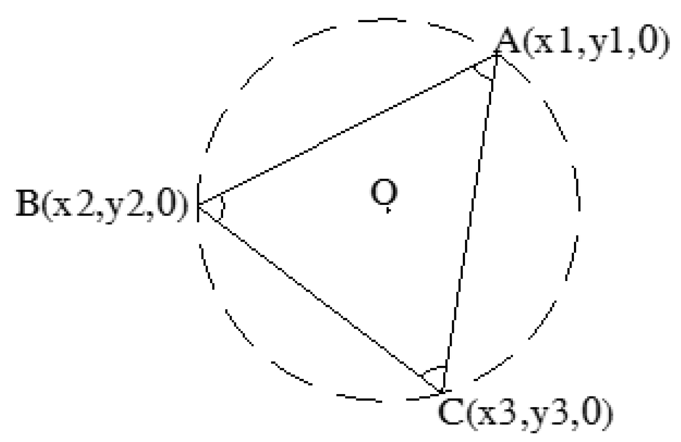
Based on geometric conditions and particle characteristics, the radius of the outer circle of the triangle can be determined first, and then the three corners of the triangle can be randomly generated to determine. According to the actual material requirements, the content of needle-shaped particles in asphalt concrete aggregates is relatively low, so acute triangles should be used as the basic unit.
By controlling the size range of the three angles of a triangle, the coordinates of points A, B, and C of the plane triangle can be calculated using the semi-valent relationship between the triangle and the circumscribed circle, as shown in
Figure 1.
2.2. Transformation Principle of Convex Geometry
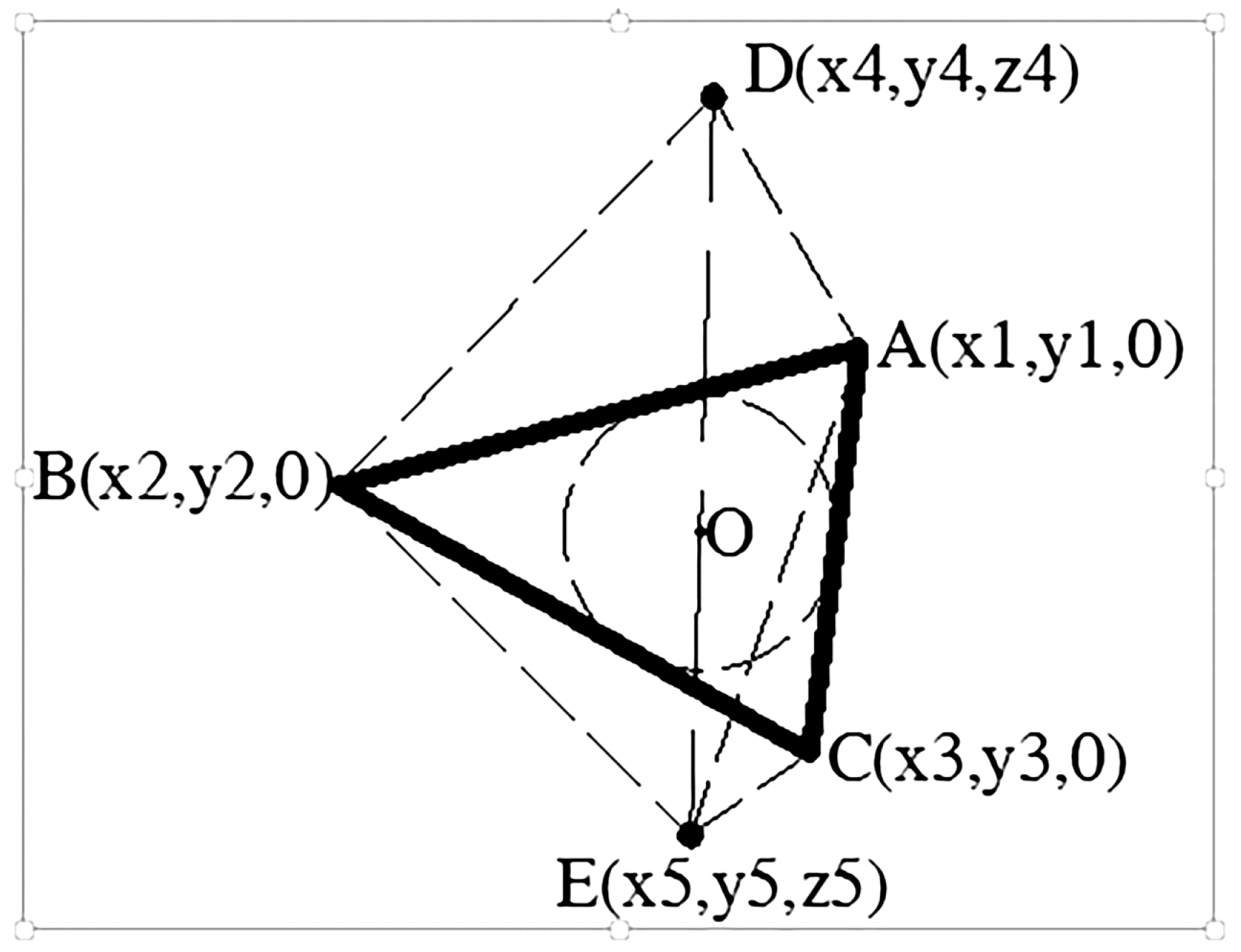
According to geometric principles, adding two arbitrary points on the outer side of the triangle plane can form a convex geometry (as shown in
Figure 2). In order to avoid generating concave particles during particle generation, the connecting line between the points on both sides of the plane triangle and the intersection point of the triangle plane should be within the triangle. To meet this requirement, first, select the intersection point between the straight line and the plane, and then randomly select points D and E on both sides of the straight line based on the characteristics of the particles. According to relevant experience, when the intersection point between the plane where the triangle is located and the connecting line on both sides is limited to the inner circle of the triangle ABC, the generated particles not only meet the requirements of concavity and convexity but also can approach the particle size.
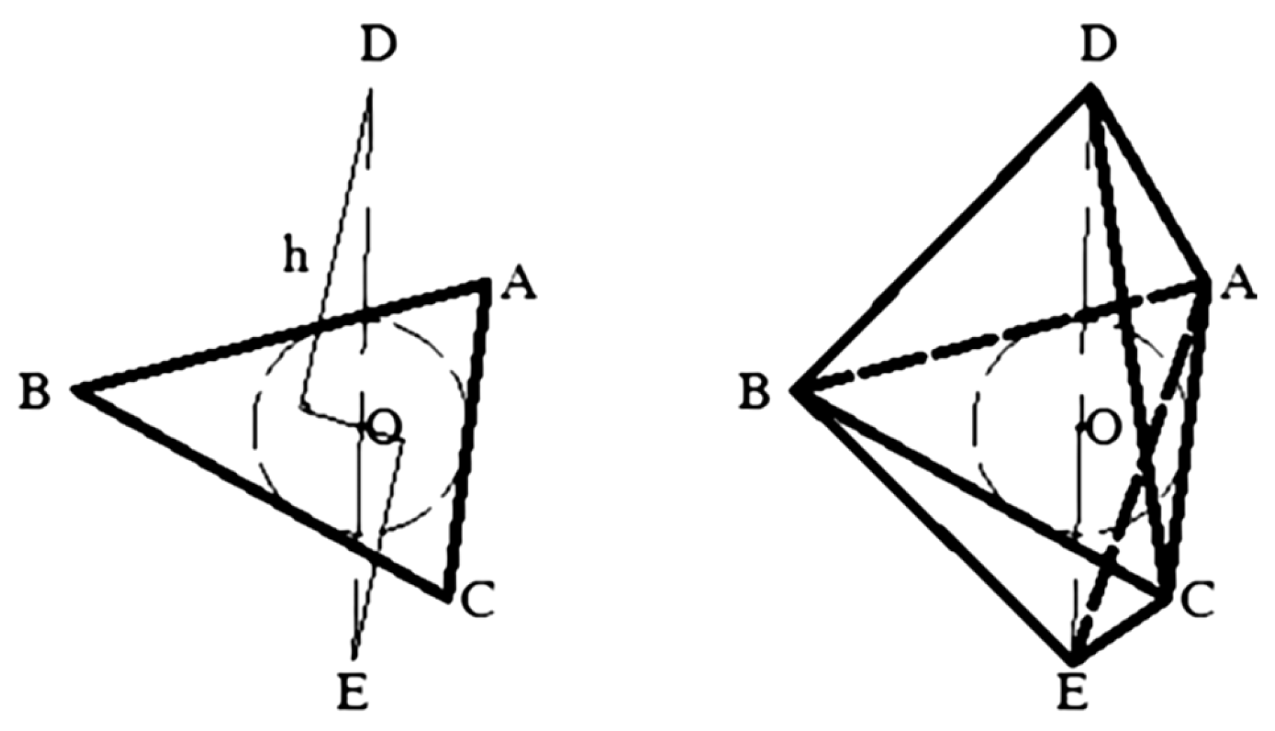
When selecting the points on both sides of the triangle ABC, the distance between the points on both sides and the plane should be limited to a certain range; otherwise, needle-like particles may occur and cannot meet the characteristics of the mixture particles. As shown in
Figure 3, h is the distance between D or E and plane ABC. After testing, in order to make the generated particles close to the actual particles of the mixture, it is advisable to control h between 0.3 R and 1.2 R during generation.
2.3. Formation of Actual Particles
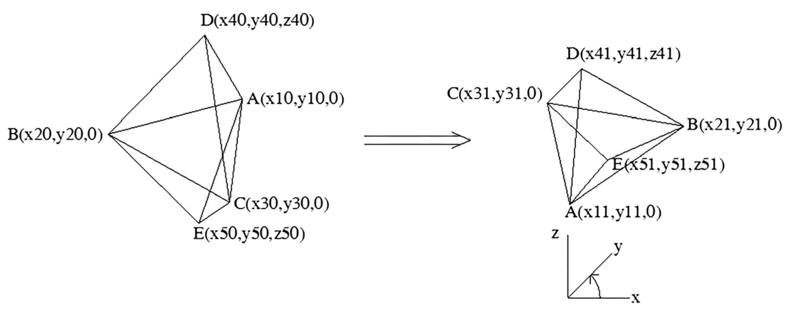
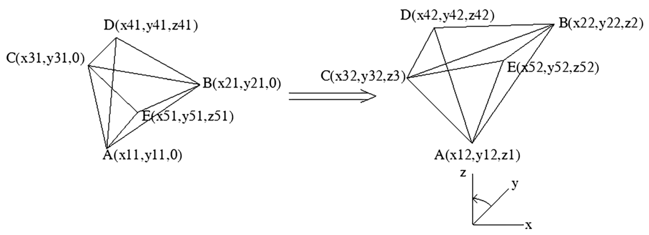
A, B, and C will form a smooth regular plane in the same plane. In order to better match the actual situation of the mixture particles, this study attempts to perform a base point transformation on convex geometry. The plan is divided into two steps to achieve this: the first step is to perform a base point transformation on the xy plane for the convex geometry; the second step is to transform the convex geometry into a base point on the zy or zx plane, as is shown in
Figure 4 and
Figure 5.
Generally, by controlling the cosine value of the triangle, the generated random triangle is an acute triangle. Any polyhedron is derived from the variation of convex geometric particles, which determine the particle size scale and the basic geometric final shape of the particles.
2.4. Expansion of Convex Geometric Particles
To ensure the diversity of particles in the formed mixture, it is necessary to randomly transform the particles. Generally, particles are extended to achieve this. There are generally two ways to implement the extension, extending along an edge of the geometry or extending along a face of the geometry. This study adopts face extension.
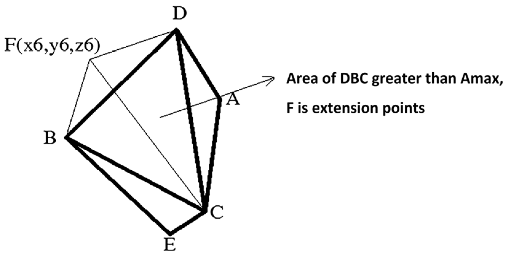
For convex geometry, select a point outside the body for expansion. To comply with the particle size of the mixture, the distance between the selected point and the convex geometric plane should be limited. For a certain face of a geometric body, randomly select a point outside the face to expand to generate a tetrahedron, and decide whether to continue expanding based on whether the area of each face of the tetrahedron is greater than the limited area. If Ai > Amax, then the face will be extended as the base face until all faces meet Ai < Amax, and then the extension will stop. Amax is the predetermined maximum area, which is related to the particle size. At the same time, it is specified that the maximum number of faces for particle expansion is 14. After all the faces that meet the conditions are expanded, if there is still Ai ≥ Amax among them, it indicates that the selection of base particle parameters is not appropriate, and new base particles should be discarded and regenerated. This cycle continues until a single particle that meets the conditions is generated.
As shown in
Figure 6, randomly select the face ADC for expansion. If the ADC area is smaller than
Amax, select point F for expansion, where the distance between F and ADC must meet the set range. As a result, the particles change from convex geometry to octahedron. Afterwards, determine the area of each octahedron surface. If a certain face is greater than
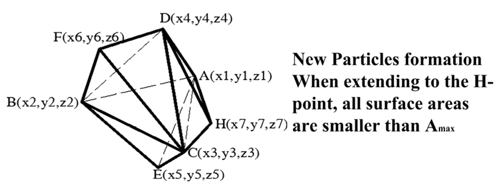
Amax, select a point outside its face to expand until all faces meet the requirements
Ai <
Amax, and then stop expanding, as shown in
Figure 7.
2.5. Correction of Elongated and Flaky Particles
The proportion of elongated and flaky particles in actual production is small. At the same time, when these particles perform Boolean operations with asphalt models in modeling, the efficiency of the asphalt model mesh division will become lower, and the number of grids will also increase, which will lead to low computational efficiency. Therefore, further correction should be made for elongated and flaky particles.
- (1)
Extraction of elongated and flaky particles.
For any particle that has been expanded, the radius of the outer circle that generates its plane triangle is R, the center point of the circle is O, and the vertices that make up the particle are denoted as P1, P2, … Pn.
Calculate the distance between any point of the particle and point O. If di > kR, make a correction to the vertex of the particle. k is the coefficient. After trial analysis, the particle shape obtained when k is between 1.8 and 2.2 is more in line with the actual situation. In this study, k = 2.0 is taken.
- (2)
Method for correcting elongated and flaky particles.
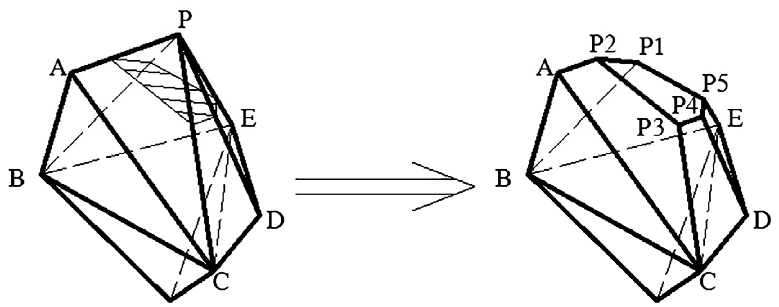
As shown in
Figure 8, assuming point P is not satisfied, it is necessary to correct the particles. The specific operation is to cut off a portion of the polyhedron with P as its vertex. The points connected to point
P are
A,
B,
C,
D, and
E. Calculate the three shortest points on the line segment connecting point
P, and set them as
A,
B, and
C. Select the midpoints of line segments
P-A,
P-B, and
P-C as
A1,
B1, and
C1, and randomly select three points
A2,
B2, and
C2 between line segments
P-A1,
P-B1, and
P-C1. Cut off the polyhedron using plane
A2-
B2-
C2. Obtain new vertices
P1,
P2,
P3,
P4,
P5, and modify the triangle planes
P-B-A,
P-A-C,
P-C-D P-D-E, and
PEB to
P1-B-A-P2,
P2-A-C-P3,
P3-C-D-P4,
P4-D-E-P5, and
P5-E-B-P1. The needle-like particles can be corrected, which is beneficial for the mesh division after modeling.
2.6. Storing Single-Particle Data
After the particles are corrected by elongated and flaky particles, the generation of particles is completed, and then the coordinates and shape data of the particles need to be stored. Each point, surface, and volume in the finite element method have corresponding coordinates. For asphalt concrete specimens with a large number of particles, it is necessary to establish corresponding data for each particle separately. Therefore, for each particle, it is not only necessary to store the coordinates of its vertices, but also the number of the points that form each face, and the number of the faces that form each body.
3. Granular Backup Option Library
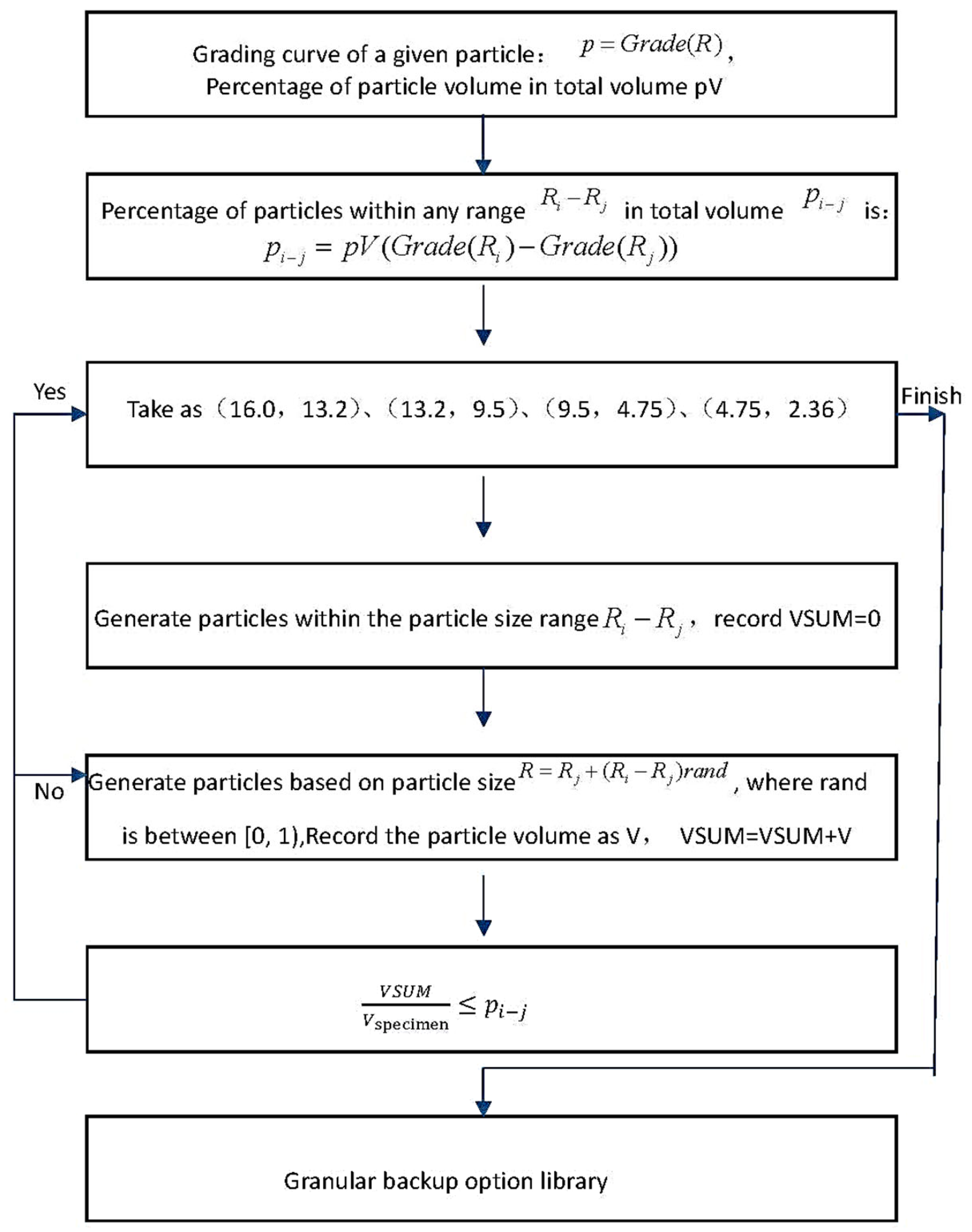
To simulate asphalt mixtures, it is necessary to determine the content of particles within each particle size range based on the grading curve. If the numerical modeling of asphalt mixtures cannot simulate their true grading curves, further in-depth research on the microstructure behavior of asphalt mixtures will not be possible. To generate a good database of particle backup options that consider actual grading, it is necessary to complete the following tasks: (1) The particle size range in the particle backup option library can provide sufficient particle sizes within the grading curve range; (2) The particle backup option library should have an efficient access method that can quickly and accurately locate the designated particles during the placement process.
After giving the particle grading curve and the percentage of particle volume to the total volume, the total volume of particles within each range can be calculated as a percentage of the total volume. Then, particles of the specified size can be randomly generated based on the particle size range, and the volume of each particle can be calculated for stacking. When the total volume of particles within this range exceeds the specified percentage of the total volume, the generation of particles within that range will be stopped, and the generation of particles within the next range will proceed. The specific process is shown in
Figure 9 (Using AC13 as an example).
4. Particle Placement
4.1. Placement Order
Particle placement is the most critical step in the generation of random particle specimens, which not only involves the utilization of the backup option library for generating particles, but also affects the efficiency of specimen generation.
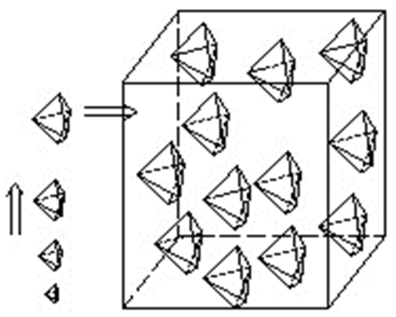
During the process of particle placement, due to the random placement, the sample space becomes smaller. Therefore, it is generally placed according to the particle size from large to small, in order to better ensure the utilization of the backup option library for generating particles, as is shown in
Figure 10.
4.2. Conflict Rules
During the placement process, particles cannot directly collide with each other (spatial polyhedra appear to intersect). The key to successful placement is to determine whether particles intersect during the placement process, as there are numerous particles and frequent determination of particle conflicts is required during the placement process. It can be said that the process of releasing particles is the process of determining whether the particles are in conflict with each other. Thus, selecting an effective conflict rule becomes a key element in the efficiency of the entire placement process.
This article is based on the fast algorithm proposed by Ren Shijun [
31,
32]. The main process is as follows:
- (1)
Four parameters are used to represent particles in three-dimensional space, with the following format:
So, any point in space can be represented as:
or:
- (2)
Any plane in a particle can be represented by three points:
P1(
x1,
y1,
z1),
P2(
x2,
y2,
z2), and
P3(
x3,
y3,
z3). The four parameters
a,
b,
c, and
d in these three-point plane equations can be represented by coordinate values
P1,
P2, and
P3:
- (3)
After obtaining the parameters a, b, c, and d, it is necessary to write the plane in an inequality format ax + by + cz < d, if the points (x,y,z) within the particle satisfy ax + by + cz > d. If not satisfied, it will be recorded as −ax – by – cz > −d;
- (4)
Then, the entire particle polyhedron can be represented as the inequality GL:
- (5)
Then, any two particles can be written as an inequality GLi and GLj, and the two inequalities can be combined to obtain the inequality GL;
- (6)
Determine whether the inequality GL is empty. If it is empty, the two particles do not conflict; otherwise, the two particles intersect.
4.3. Placement Process
As the space available for placement decreases during the placement process, it becomes more difficult to find the placement point of the final particles, resulting in the need for more cycles in the program. During the process of particle placement, it is necessary to determine whether the particles have left the boundary and whether they conflict with the position of the already placed particles. If there is a conflict, it needs to be re-launched. This article selects the following steps for dispensing to achieve fast and accurate dispensing of particles.
- (1)
The particles in the generated particle backup option library are sorted in descending order of particle size, and the larger particles are added first when adding them. Set the total initial number of drops to M = 0, and the number of single particles drops to DN. The maximum number of times a single particle drops to MAX1, and the maximum number of times a total particle drops to MAX2.
- (2)
Set the particle placement for this time as Si, radius is Ri, DN = 0.
- (3)
Randomly generate a delivery point Pi, and determine whether the particle has exited the boundary after delivery. If the delivery point does not meet the requirements, select the delivery point again until the requirements are met.
- (4)
Set any particle that has been placed as Sj, and L is the distance Pi from Pj. Record the particle number Ri + Rj > kL that is valid (due to the difference in particle size between a polyhedron and a sphere, the coefficient k is taken as a value less than 1. In order to select all possible and intersecting particles, this article has conducted multiple experiments and selected 0.5), and stored the recorded particle number in the matrix KS.
- (5)
Determine Si if there is a conflict with particles in KS.
Conflict: then, DN = DN + 1. If N > MAX1, adjust to (8); otherwise, skip to (3).
No conflict: This placement was successful, and the placement point Pi is the center point of Si.
- (6)
Number the particles that have been placed in sequence, and record them in matrix S. Record the center point of the particles in matrix P, and record the particle radius in matrix R.
- (7)
M = M + DN, if M >= MAX2, end placement, return.
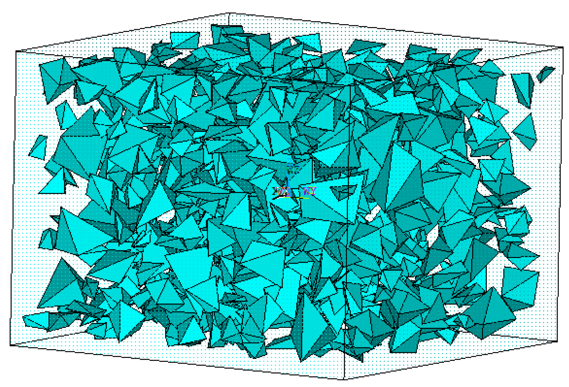
- (8)
Enter the next particle placement, and the results is shown in
Figure 11.
5. Model Building
The random particle model of asphalt concrete is a simplified model for pavement asphalt concrete specimens at a microscopic level. This model simulates the random distribution of particles in asphalt in reality, which can be closer to the actual situation of asphalt concrete and can also accurately obtain theoretical data.
This article studies a mesoscopic random particle model. There are hundreds of thousands of units. If modeled according to the actual size, the number of model units will be very large, so it is necessary to reduce the simulation of the actual model.
The random particle model of asphalt concrete in this article has a shape of 80 mm × 80 mm × 60 mm rectangular body. Before randomly generating particles, it is necessary to specify the origin of the coordinate system to facilitate modeling and post-processing analysis. The model established in this article is a rectangular asphalt concrete specimen, with the middle plane of the specimen as the xoy plane. The established coordinate system is shown in
Figure 12.
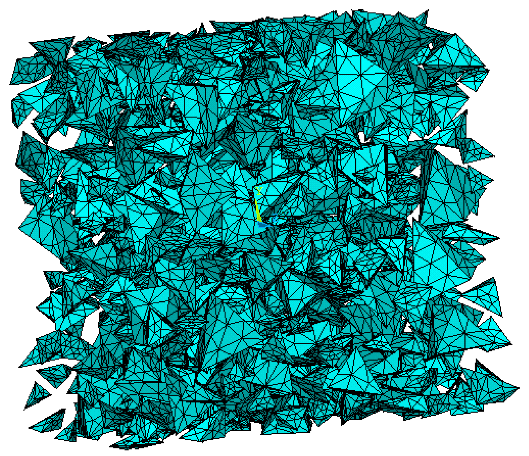
Limestone particles were selected, with an elastic modulus of 40 GPa and a Poisson’s ratio of 0.2. The particle models used in this article are all convex particles and all are polygonal particles. SLOID45 element is used to simulate particles (
Figure 13).
Asphalt sand adopts the viscoelastic Burgers model. The various parameters of the asphalt sand used in this article are shown in
Table 1.
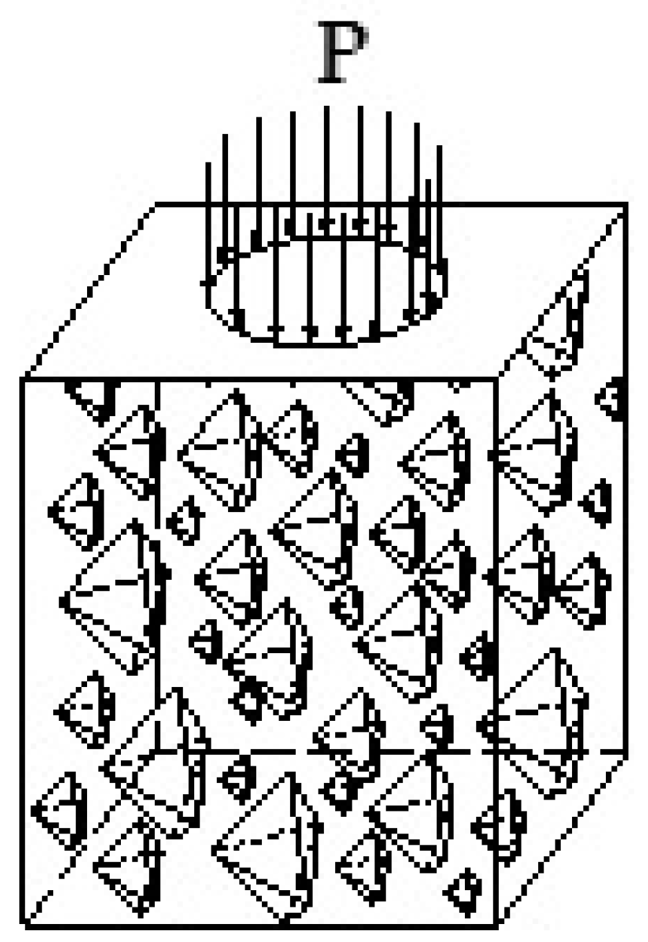
In order to approach the actual situation, the uniformly distributed load on the surface of the specimen model is equivalent to the actual tire pressure, and the area of action of the uniformly distributed load is reduced by the corresponding multiple of the model.
The tire pressure P is 0.707 MPa, so the uniformly distributed load is taken as 0.707 MPa. The load is a uniformly distributed circular load with a radius of 10 mm, with a vertical downward direction.
Constrain the normal displacement on all sides of the specimen, and also constrain the normal displacement on the bottom surface of the specimen. The top surface under load is a free surface, the schematic diagram is shown in
Figure 14.
6. Numerical Simulation
6.1. Displacement
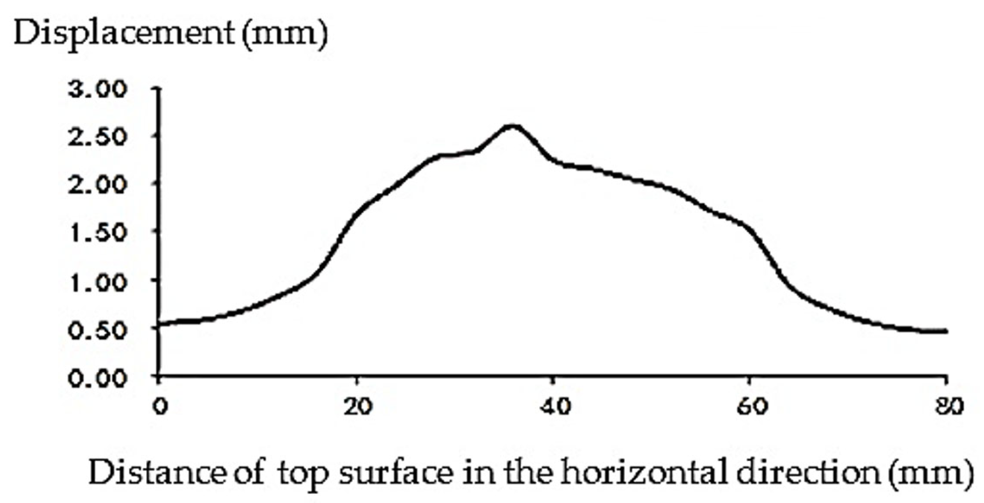
The change in displacement of the top surface in the horizontal direction of a straight line along the
x-axis direction is shown in
Figure 15.
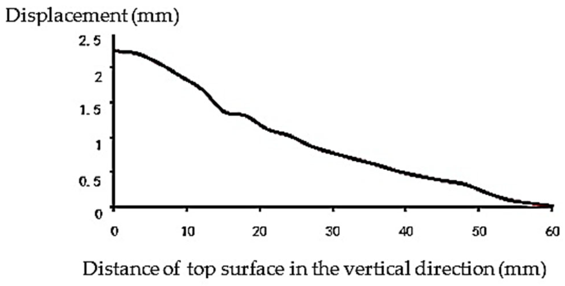
The displacement change in the vertical direction of the center of the specimen is shown in
Figure 16.
The displacement diagram of
Figure 15 and
Figure 16 indicates that there is a certain displacement change in the asphalt pavement displacement considering aggregates in a relatively homogeneous model, but the overall trend is consistent.
6.2. Stress
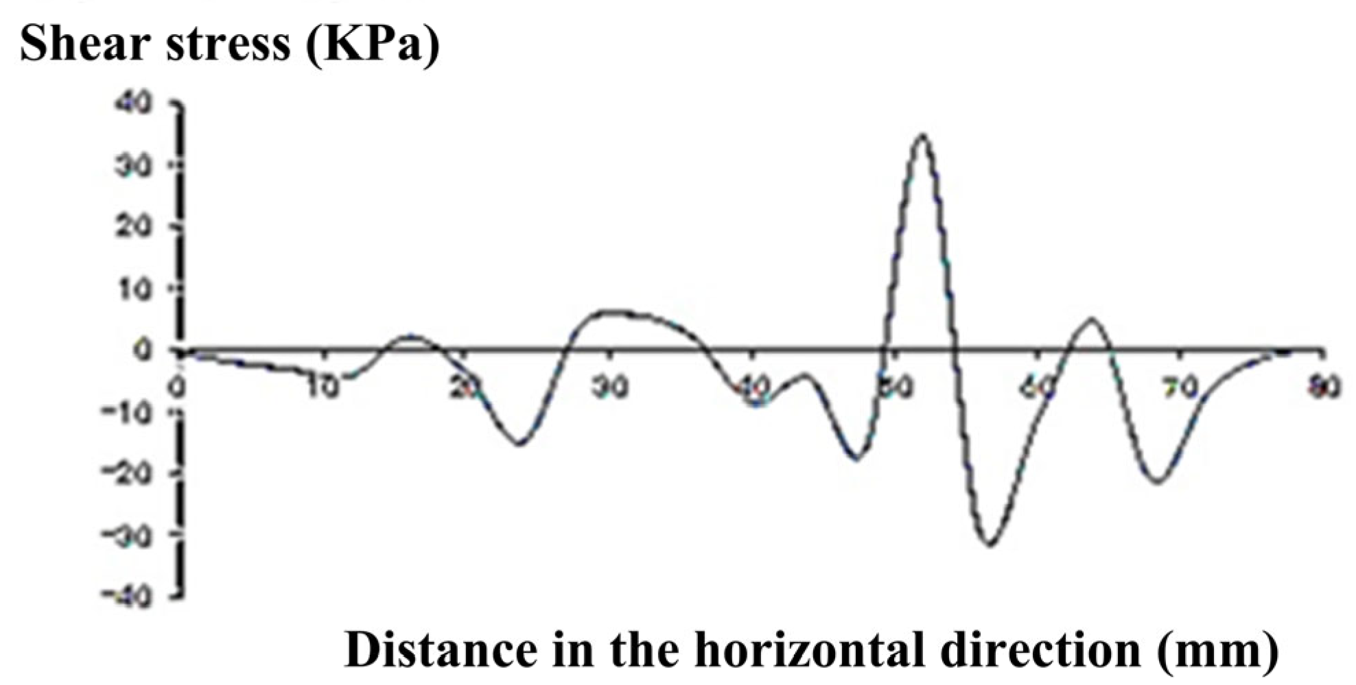
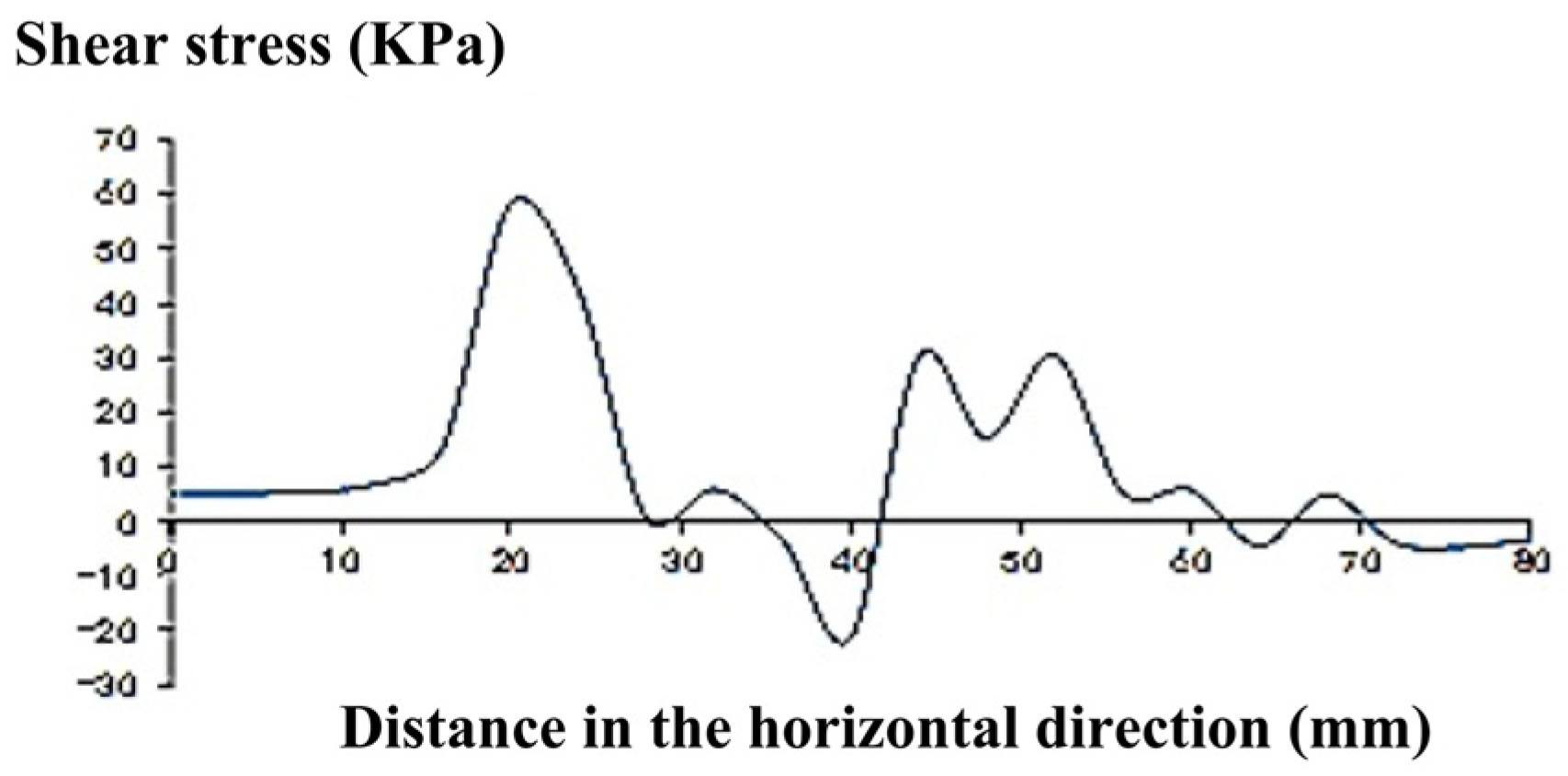
Study the variation of shear stress in straight lines (x = −40, y = 0, z = 0) − (x = 40, y = 0, z = 0). The variation diagram of shear stress S
XZ, S
YZ, and S
XY with position is shown in
Figure 17,
Figure 18 and
Figure 19.
Study the variation of tensile stress in straight lines (x = −40, y = 0, z = −30) − (x = 40, y = 0, z = −30). The variation diagram of tensile stress with position is shown in
Figure 19.
The stress diagram of
Figure 17,
Figure 18 and
Figure 19 indicates that there is a significant correlation between the stress of asphalt concrete pavement and the changes in particle arrangement when considering particle stress. This provides a good mechanical analysis tool for the microscopic study of particles and their connections, laying the foundation for future research.
7. Conclusions
Based on the asphalt mixture ratio, this paper further improves the algorithm for generating random particles, optimizes the algorithm for generating individual particles, ensures that the shape of particles during generation conforms to engineering practice, forms a random particle backup library, proposes a particle placement method, and forms a random aggregate model for asphalt concrete. The model is used for numerical analysis. The result shows that when considering particle forces on asphalt concrete pavement, there is a significant correlation between its stress and changes in particle arrangement. This study provides a good mechanical analysis tool for the microscopic study of particles and their connections, laying the foundation for future research.
Author Contributions
Conceptualization, J.J.; Methodology, J.J. and X.L.; Software, J.J.; Validation, J.J. and X.L.; Investigation, J.J. and X.Z.; Resources, X.Z. and X.L.; Writing—original draft, J.J.; Writing—review & editing, X.L.; Supervision, J.J. and X.Z.; Visualization X.Z.; Data curation X.Z. All authors have read and agreed to the published version of the manuscript.
Funding
This work was supported by the Natural Science Foundation of Hunan province (No. 2022JJ30930), and the Transportation Science and Technology Project of Hunan province (No. 202246).
Data Availability Statement
Some or all data, models, or code that support the findings of this study are available from the corresponding author upon reasonable request.
Acknowledgments
The authors are thankful to CHEN Hua’an for his effort in layout editing.
Conflicts of Interest
The authors declare no conflict of interest.
References
- Yu, H.; Ding, Y.; Qian, G.; Zhu, X.; Shi, C.; Zhang, C.; Li, P. Review on Digital Twin Model of Asphalt Mixture Performance Based on Mesostructure Characteristics. China J. Highw. Transp. 2023, 36, 20–44. [Google Scholar] [CrossRef]
- Sun, L.; Qian, G.; Huang, S.; Dong, Z.; Chen, J.; Wang, X.; Wang, L.; Liu, L. Research Progress on Intelligent Simulation Theory and Mehod for Service Performance of Road Infrastructure. China Basic Sci. 2021, 23, 6–15. [Google Scholar]
- Ribas, C.Y.; Thives, L.P. Evaluation of effect of compaction method on the macrostructure of asphalt mixtures through digital image processing under Brazilian conditions. Constr. Build. Mater. 2019, 228. [Google Scholar] [CrossRef]
- Zhang, Q.; Xiao, X. Research review on constitutive model and microstructure of asphalt and asphalt mixture. China J. Highw. Transp. 2016, 29, 26–33. [Google Scholar] [CrossRef]
- Upshaw, M.; Cai, C.S. Critical Review of Recycled Aggregate Concrete Properties, Improvements, and Numerical Models. J. Mater. Civ. Eng. 2020, 32, 03120005. [Google Scholar] [CrossRef]
- Abd Elrahman, M.; Chung, S.-Y.; Stephan, D. Effect of different expanded aggregates on the properties of lightweight concrete. Mag. Concr. Res. 2019, 71, 95–107. [Google Scholar] [CrossRef]
- Gora, J.; Piasta, W. Impact of mechanical resistance of aggregate on properties of concrete. Case Stud. Constr. Mater. 2020, 13, e00438. [Google Scholar] [CrossRef]
- Abd Elhakam, A.; Mohamed, A.E.; Awad, E. Influence of self-healing, mixing method and adding silica fume on mechanical properties of recycled aggregates concrete. Constr. Build. Mater. 2012, 35, 421–427. [Google Scholar] [CrossRef]
- Gucluer, K. An investigation of the effect of different aggregate types on concrete properties with thin section and nondestructive methods. J. Eng. Res. 2021, 9, 15–24. [Google Scholar] [CrossRef]
- Gucluer, K. Investigation of the effects of aggregate textural properties on compressive strength (CS) and ultrasonic pulse velocity (UPV) of concrete. J. Build. Eng. 2020, 27, 100949. [Google Scholar] [CrossRef]
- Jiang, R.; Xing, Y.; Liu, S.; Guo, Y.; Guo, B. Study on the Preparation and Properties of Bridge Concrete Using Low Carbon Aggregates. Materials 2023, 16, 245. [Google Scholar] [CrossRef]
- Fang, M.; Park, D.; Singuranayo, J.L.; Chen, H.; Li, Y. Aggregate gradation theory, design and its impact on asphalt pavement performance: A review. Int. J. Pavement Eng. 2019, 20, 1408–1424. [Google Scholar] [CrossRef]
- Karki, P.; Kim, Y.-R.; Little, D.N. Dynamic Modulus Prediction of Asphalt Concrete Mixtures Through Computational Micromechanics. Transp. Res. Rec. 2015, 2507, 1–9. [Google Scholar] [CrossRef]
- Cao Thanh Ngoc, T.; Li, B. Analytical Model for Shear-critical Reinforced Concrete Interior Beam-column Joints. J. Earthq. Eng. 2020, 24, 1205–1221. [Google Scholar] [CrossRef]
- Baby, F.; Marchand, P.; Toutlemonde, F. Analytical Modeling of Ultra-High-Performance Fiber-Reinforced Concrete Behavior in Ribbed Plates. Aci Struct. J. 2017, 114, 3–13. [Google Scholar] [CrossRef]
- Lee, J.; Nishiyama, M.; Kono, S.; Sakashita, M. Shear Resistance Mechanism of Posttensioned Precast Concrete Members. J. Struct. Eng. 2013, 139, 04013007. [Google Scholar] [CrossRef]
- Wang, B.T.; Zhou, X.G. Model of random polygon particles for concrete and mesh automatic subdivision. J. Wuhan Univ. Technol. ater. Sci. Ed. 2001, 16, 36–40. [Google Scholar]
- Zhou, H.; Li, J.; Spencer, B.F., Jr. Multiscale Random Fields-Based Damage Modeling and Analysis of Concrete Structures. J. Eng. Mech. 2019, 145, 04019045. [Google Scholar] [CrossRef]
- Guan, C.S.; Han, G.D.; Singhal, A. Numerical method and random analysis of cement concrete expansion. J. Wuhan Univ. Technol. Mater. Sci. Ed. 2000, 15, 66–72. [Google Scholar]
- Liang, S.; Ren, X.; Li, J. A random medium model for simulation of concrete failure. Sci. China-Technol. Sci. 2013, 56, 1273–1281. [Google Scholar] [CrossRef]
- Kirgiz, M.S. Effect of mineralogical substitution raw material mixing ratio on mechanical properties of concrete. Zkg Int. 2018, 71, 30−+. [Google Scholar]
- Mazian, B.; Wirquin, E.; Aguibi, K.; Martin, P.; Chaveriat, L.; Dubois, V. Effect of mixing conditions on the density, morphology, thermal and mechanical properties of mineral foam. J. Build. Eng. 2022, 52, 104410. [Google Scholar] [CrossRef]
- Zhang, C.; Sun, Y.; Xu, J.; Wang, B. The Effect of Vibration Mixing on the Mechanical Properties of Steel Fiber Concrete with Different Mix Ratios. Materials 2021, 14, 3669. [Google Scholar] [CrossRef] [PubMed]
- Wang, Q.; Liu, Y.; Wang, D. Effects of replacement ratio and particle size distribution of recycled coarse aggregate on mechanical properties of concrete designed using equivalent mortar volume method. Struct. Concr. 2022, 24, 1821–1834. [Google Scholar] [CrossRef]
- Ozbay, E.; Gesoglu, M.; Guneyisi, E. Transport properties based multi-objective mix proportioning optimization of high performance concretes. Mater. Struct. 2011, 44, 139–154. [Google Scholar] [CrossRef]
- Dong, G. Meso-Model and Pure Torsion Simulation of Asphalt Mixture Based on Random Coarse Aggregate. Master’s Thesis, Dalian University of Technology, Dalian, China, 2020. [Google Scholar] [CrossRef]
- Bin, X. Study on Micromechanical Properties and Evolution Behavior of Asphalt Mixture. Ph.D. Thesis, Chang’an University, Chang’an, China, 2020. [Google Scholar] [CrossRef]
- Adessina, A.; Ben Fraj, A.; Barthelemy, J.-F.; Chateau, C.; Garnier, D. Experimental and micromechanical investigation on the mechanical and durability properties of recycled aggregates concrete. Cem. Concr. Res. 2019, 126, 105900. [Google Scholar] [CrossRef]
- Chen, Q.; Zhu, Z.; Liu, F.; Li, H.; Jiang, Z. Micromechanical investigation for the probabilistic behavior of unsaturated concrete. Comput. Concr. 2020, 26, 127–136. [Google Scholar] [CrossRef]
- Lezgy-Nazargah, M.; Emamian, S.A.; Aghasizadeh, E.; Khani, M. Predicting the mechanical properties of ordinary concrete and nano-silica concrete using micromechanical methods. Sadhana-Acad. Proc. Eng. Sci. 2018, 43, 196. [Google Scholar] [CrossRef]
- Ren, S.; Hong, B. A fast algorithm to determine whether convex regions bounded by multiple linear constraints are empty. Chin. J. Comput. 1998, 10, 896–901. [Google Scholar]
- Ren, S.; Hong, B.; Meng, Q. A fast algorithm to determine whether the intersection of two convex regions is empty. J. Softw. 2000, 11, 563–568. [Google Scholar] [CrossRef]
Figure 1.
Relationship between simple triangle and circumcircle.
Figure 1.
Relationship between simple triangle and circumcircle.
Figure 2.
Transformation Principle of Convex Geometry.
Figure 2.
Transformation Principle of Convex Geometry.
Figure 3.
Convex geometry transformation process.
Figure 3.
Convex geometry transformation process.
Figure 4.
Base point transformation of convex geometry in the xy plane.
Figure 4.
Base point transformation of convex geometry in the xy plane.
Figure 5.
Transformation of convex geometry at yz base point.
Figure 5.
Transformation of convex geometry at yz base point.
Figure 6.
Surface extension of convex geometry.
Figure 6.
Surface extension of convex geometry.
Figure 7.
Formation of mixture particles.
Figure 7.
Formation of mixture particles.
Figure 8.
Correction of elongated and flaky particles.
Figure 8.
Correction of elongated and flaky particles.
Figure 9.
Block diagram of particle backup option library formation.
Figure 9.
Block diagram of particle backup option library formation.
Figure 10.
Schematic diagram of placement sequence.
Figure 10.
Schematic diagram of placement sequence.
Figure 11.
Placement results.
Figure 11.
Placement results.
Figure 12.
Coordinate system and rectangular body.
Figure 12.
Coordinate system and rectangular body.
Figure 13.
Particle division.
Figure 13.
Particle division.
Figure 14.
Loading method of specimen model.
Figure 14.
Loading method of specimen model.
Figure 15.
Displacement of x-axis direction of the top surface.
Figure 15.
Displacement of x-axis direction of the top surface.
Figure 16.
Displacement of Z-axis direction at the center of the specimen.
Figure 16.
Displacement of Z-axis direction at the center of the specimen.
Figure 17.
Variation of shear stress SXZ.
Figure 17.
Variation of shear stress SXZ.
Figure 18.
Variation of shear stress SYZ.
Figure 18.
Variation of shear stress SYZ.
Figure 19.
Variation of shear stress SXY.
Figure 19.
Variation of shear stress SXY.
Table 1.
Parameters of the asphalt sand.
Table 1.
Parameters of the asphalt sand.
| T (°) | g1 | g2 | τ1 |
|---|
| 4.4 | 0.5899 | 0.4101 | 89.9143 |
| 64 | 0.0094 | 0.9906 | 14.1169 |
| Disclaimer/Publisher’s Note: The statements, opinions and data contained in all publications are solely those of the individual author(s) and contributor(s) and not of MDPI and/or the editor(s). MDPI and/or the editor(s) disclaim responsibility for any injury to people or property resulting from any ideas, methods, instructions or products referred to in the content. |
© 2023 by the authors. Licensee MDPI, Basel, Switzerland. This article is an open access article distributed under the terms and conditions of the Creative Commons Attribution (CC BY) license (https://creativecommons.org/licenses/by/4.0/).
