Article

Flexural Behavior of Cold-Formed Steel Composite Floor Infilled with Desert Sand Foamed Concrete

1
Guiyang Engineering Corporation Limited of Power China, Guiyang 550081, China
2
School of Civil Engineering, Chongqing University, Chongqing 400045, China
3
Key Laboratory of New Technology for Construction of Cities in Mountain Area (Chongqing University), Ministry of Education, Chongqing 400045, China
*
Author to whom correspondence should be addressed.
Buildings 2023, 13(5), 1217; https://doi.org/10.3390/buildings13051217
Submission received: 14 April 2023 / Revised: 29 April 2023 / Accepted: 30 April 2023 / Published: 5 May 2023
(This article belongs to the Special Issue Prefabricated and Modular Steel Structures)

Abstract

:
Desert sand foamed concrete (DSFC), which offers advantages, such as fire resistance, sound insulation, construction convenience, and environmental benefits, has not been used in cold-formed steel (CFS) composite floors. In this study, four full-scale specimens were designed and tested under four-point bending to investigate the effect of foamed concrete filling and holes. The load–deflection curves and strain distribution at mid-span were measured and analyzed. The experimental results indicated that the failure modes of the CFS composite floors were local buckling at the top flange for specimens without holes and tensile failure at the bottom flange for specimens with holes, respectively, which differed from the web crippling observed in non-composite floors. Moreover, due to the presence of foamed concrete, the flexural stiffness was significantly improved by 117.6% and 73.6% for the specimens without holes and with holes, respectively, while ultimate capacity increased by 224.9% and 121.8%, respectively. Through the nonlinear finite element models validated against experimental results, it was found that the flexural behavior was improved with the increase in CFS thickness and foamed concrete strength. The impact of the holes was not obvious for specimens infilled with holes.

1. Introduction

Cold-forming is an industrial process that involves cold-rolling, brake-forming, and bending brake operations to transform flat steel panels into various sections. Due to the effects of cold forming, CFS exhibits significantly higher yield strength. This higher strength allows for thinner section thickness and lower steel consumption. However, thinner sections with lower width-to-thickness ratios increase the possibility of local buckling in compression zones, which can result in reduced cross-sectional area (effective section method) or diminished strength (direct strength method). To address this challenge in CFS floor systems, composite action can be introduced. The material with higher compressive strength in the compression zone can share compressive stress in CFS and also limit local deformation through the coating, infilling, or ample connections.
Concrete is the most commonly used building material due to its outstanding performance, and it was initially considered as a composite material for use in CFS floor systems. Hanaor [1] summarized typical configurations of composite sections and identified the key issue in implementing these designs as ensuring sufficient shear transfer between the concrete slab and the CFS beam. Full-scale experimental results demonstrated higher ductility and capacity than design assumptions. Subsequent studies, including experimental and numerical analyses on various shear connectors, were conducted by M. Hosseinpour et al. [2,3,4]. The most popular type of CFS floor system at present is the composition among the mortar casting in site, profiled steel plates, and joists or trusses considering the convenience of construction, and studies related to strength, stiffness, and ductility have been published in [5,6,7]. Meanwhile, compression zones, such as top flanges and top chords, have been embedded in concrete to improve composite action and limit local deformation in various studies [8,9]. All specimens showed similar failure modes with high ductility, namely the tension yielding of bottom flanges or chords.
Wood-based boards, such as oriented strand boards (OSBs), have been used to resist compression in CFS composite floors as structural sheathings, in addition to concrete. Xu et al. [10] investigated the vibration performance of lightweight residential floors supported by CFS C-shape joists sheathed with OSBs, while Zhou et al. [11] focused on flexural capacity and proposed a simplified evaluation method. Kyvelou et al. [12] conducted a series of four-point bending tests to examine the overall behavior and shear transfer mechanisms of self-drilling screws and structural adhesive, while Li et al. [13] proposed a new type of lightweight I-section bamboo–steel composite beam utilizing adhesive bonding.
In recent years, many innovative composite floor systems have been proposed and tested. In addition to mechanical properties, materials now need to fulfill additional functions, such as fire resistance, sound insulation, construction convenience, and environmental benefits. Tian et al. [14] proposed a new lightweight composite floor consisting of CFS trusses and a gypsum-based expanded polystyrene granule mortar (GEPM) slab which simplified floor details, improved sound and vibration absorption performance, and increased fire resistance. Shi et al. [15] applied gypsum-based self-leveling underlayment (GSU) cast on the profiled steel plate to CFS composite floors due to its ease of construction, cost efficiency, non-combustibility, and satisfactory serviceability performance. Wang et al. [6,7] combined CFS trusses with assembled autoclaved lightweight concrete (ALC) slabs to improve the assembly site. The flexural behavior out-of-plane and cyclic behavior in-plane were investigated.
Based on the above studies, an innovative CFS composite floor infilled with desert sand foamed concrete (DSFC) is proposed. Desert sand can be used in civil engineering instead of river sand as an environment-friendly resource with rich reserves. It also has advantages in terms of price and transport, particularly in regions adjacent to deserts. Using desert sand as the fine aggregate of foamed concrete not only reduces costs but also minimizes environmental damage. Extensive basic research achievements [16,17,18,19,20,21] on desert sand concrete have been published. In this study, DSFC was utilized as a filler to provide constraints for cold-formed thin-walled steel joists, which had lighter self-weight and improved thermal insulation performance. Calcium silicate boards (CSBs) were applied to decrease formwork. Four full-scale specimens were designed to investigate flexural behavior considering the effects of foamed concrete filling and holes, and were loaded through four-point bending tests. Nonlinear finite element models were developed and validated against experimental results. Parametric analyses were conducted by the verified FE models to assess the influences of CFS thickness, foamed concrete strength, and hole spacing.

2. Experimental Program

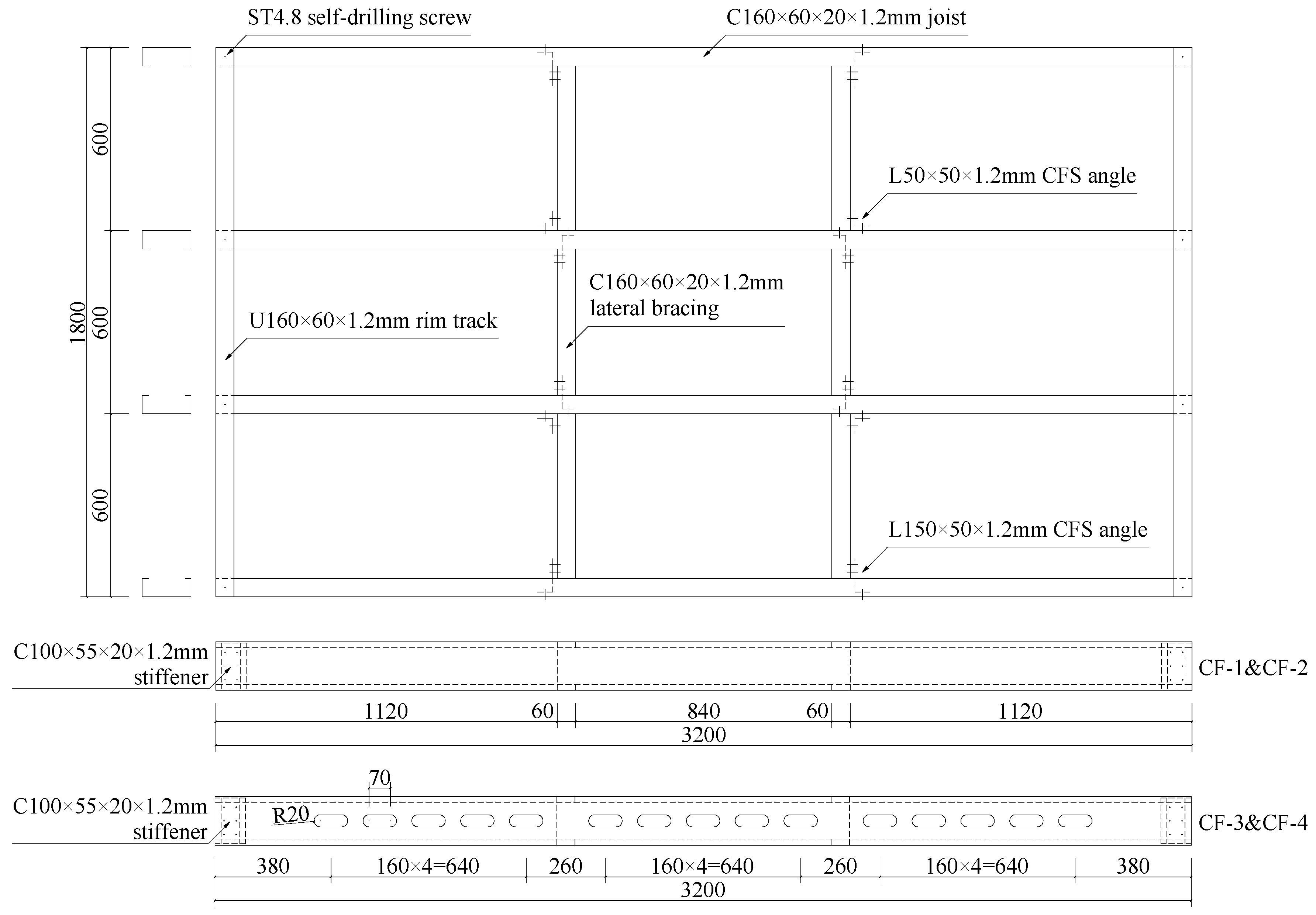
2.1. Specimen Details and Fabrication

Four full-scale floor specimens were fabricated to investigate the influences of desert sand foamed concrete filling and holes on flexural behavior. The general information of specimens is listed in Table 1.
All specimens were 3200 mm long and 1800 mm wide with a 600 mm joist spacing. The joists with a section of C160 × 60 × 20 × 1.2 mm (height × width × lip length × thickness) were framed into an 1800 mm long U160 × 60 × 1.2 mm (height × width × thickness) CFS U-shape rim track at each end, and were fastened by ST4.8 self-drilling screws with an edge distance of 30 mm. To avoid possible local failure of end supports under a concentrated reaction, CFS stiffeners with a section of C100 × 55 × 20 × 1.2 mm were fastened to the web at each end of the joists with six ST4.8 screws. In addition, lateral bracing with a section of C160 × 60 × 20 × 1.2 mm was arranged at the trisection point and connected to the joists by ST4.8 screws and CFS angle steel. The general configuration of CFS framing is illustrated in Figure 1, while connection details are shown in Figure 2.
The layouts of CSBs and self-drilling screws are depicted in Figure 3. The section details of the specimens are shown in Figure 4. For specimens CF-1 and CF-2, CSBs were placed on both the top and bottom flanges and connected using ST4.8 self-drilling screws with a spacing of 140–150 mm. For specimens CF-3 and CF-4, CSBs were only placed on the bottom flanges to serve as formwork. DSFC was cast in and covered the top flange up to 30 mm. It should be noted that 10 × 10 × 1 mm steel wire meshes were embedded at the middle position of the top 30 mm DSFC to limit crack expansion.

2.2. Material Properties

The material property test process is shown in Figure 5. The material properties of the LQ550 cold-formed thin-walled steel were determined through metallic material tensile tests in accordance with GB/T 228.1-2021 [22]. Three coupons were tested, and stress–strain curves are shown in Figure 6, while the results are presented in Table 2. It is obvious that LQ550 cold-formed thin-walled steel, as a high-strength material, exhibited minimal strain hardening and poor ductility.
Desert sand has a smaller particle size than natural river sand and manufactured sand. Desert sand from Lingshou County in Hebei Province was selected for this study, and its gradation is listed in Table 3. The mix proportions of the foamed concrete are listed in Table 4, where the cement was PO 42.5 ordinary Portland cement with a water–cement ratio of 0.28; the polycarboxylic high-efficiency water-reducing agent was used with a solid-liquid ratio of 0.4; the foaming agent used is the plant-based concrete foaming agent; polypropylene fiber with a volume ratio of 0.1% (0.9 kg/m3) was added to limit the shrinkage of foamed concrete and improve its bonding behavior with cold-formed thin-walled steel. The mechanical properties of the DSFC were obtained based on JG/T 266-2011 [23]. Three 100 × 100 × 100 mm cubic coupons were reserved during casting and cured under the same environment. Density, compression strength, and elastic modulus were measured, and the results are listed in Table 5. The material properties of the CSBs were obtained from the test report provided by the manufacturer, and summarized in Table 6.

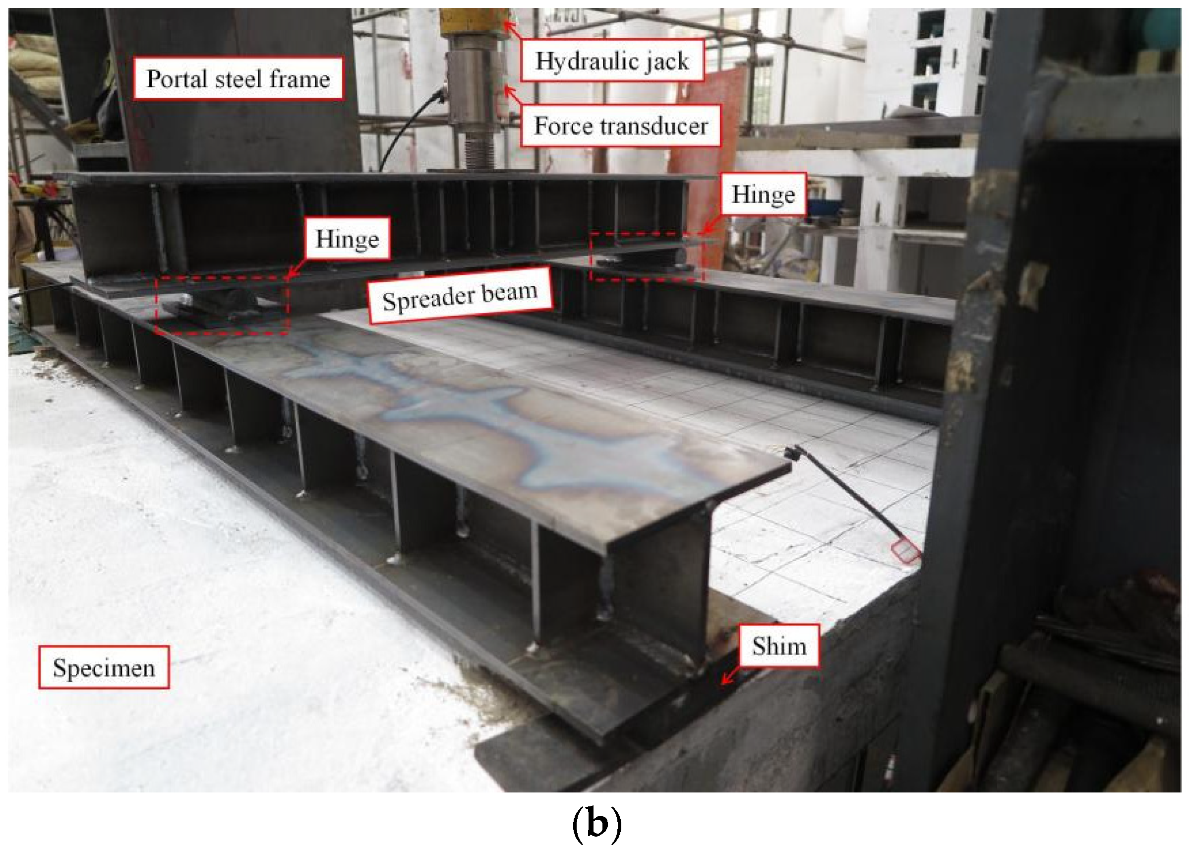
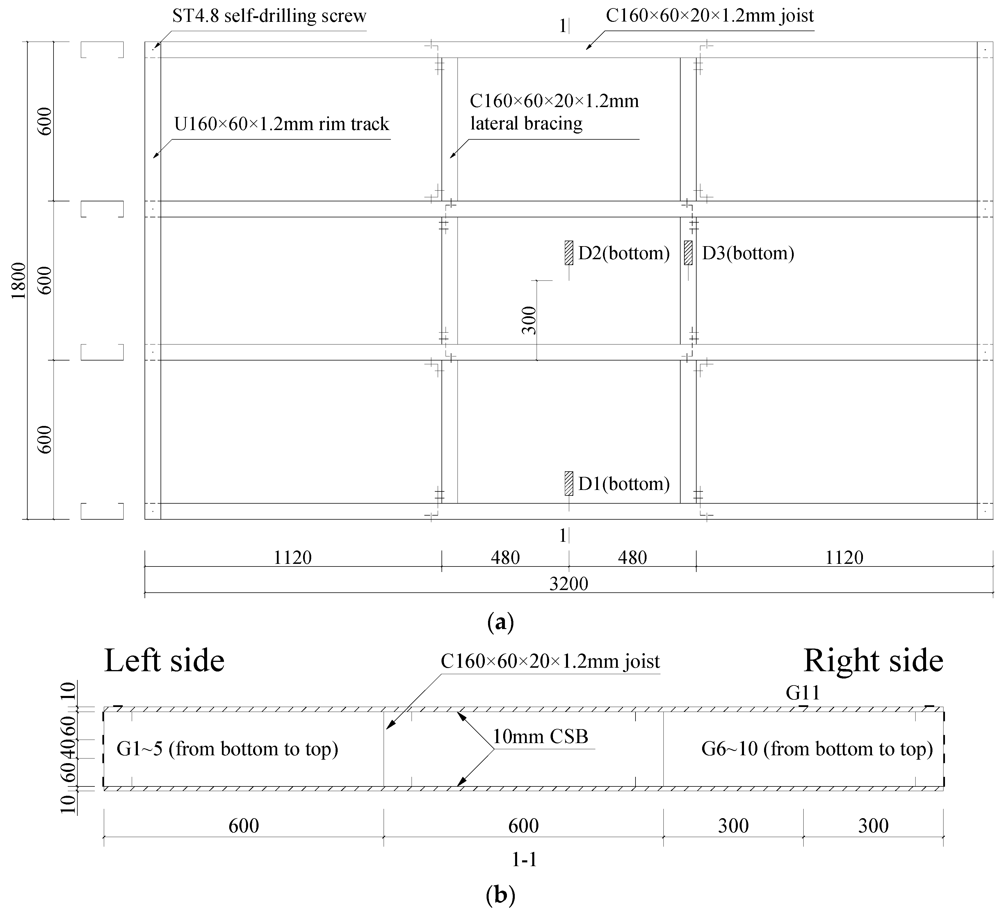
2.3. Test Set-Up and Procedure

In this study, two concentrated loads were applied at one-third of the span length to induce a pure bending moment on the mid-span of the composite floor for investigating its flexural behavior. The test set-up is shown in Figure 7. Steel blocks and steel beams were used as rigid supports, with hinge supports fixed on top to achieve simply supported boundary conditions. The specimen was supported on hinge supports at both ends, with a support length of 3000 mm. The loading width was controlled by shims to be 100 mm. A hydraulic jack was used for loading. Reaction forces were provided by the portal steel frame, and load distribution was achieved through spreader beams and hinges.
The layout of transducers is illustrated in Figure 8. Considering the symmetry of the composite floor, the linear variable differential transformers (LVDTs) D1–D3 were used to measure the deflection of the composite floor within the half-span range. D1 and D2 were placed at the mid-span, while D3 was placed at the one-third span. Strain gauges G1–G11 were used to measure the strain distribution at the mid-span section of the composite floor to analyze the stress distribution of the maximum bending moment section and to verify whether the plane section assumption was valid.
Preloading is a very important part of the experiment, which can ensure full and tight contact between the device and specimen. It can also be used to test the reliability of the equipment and check whether the measuring instruments are working properly. In this study, preloading was carried out at a speed of 5 kN/min and unloaded when it reached 20 kN. The formal loading was performed in stages, with a loading increment of 10 kN at a speed of 5 kN/min. After the loading was completed, the load was held for 3 min. When the load reached its peak and stopped increasing, the loading controlled by displacement continued at a speed of 0.5 mm/min until the load dropped to 80% of the peak load, and then the loading was stopped.

3. Experimental Results and Discussion

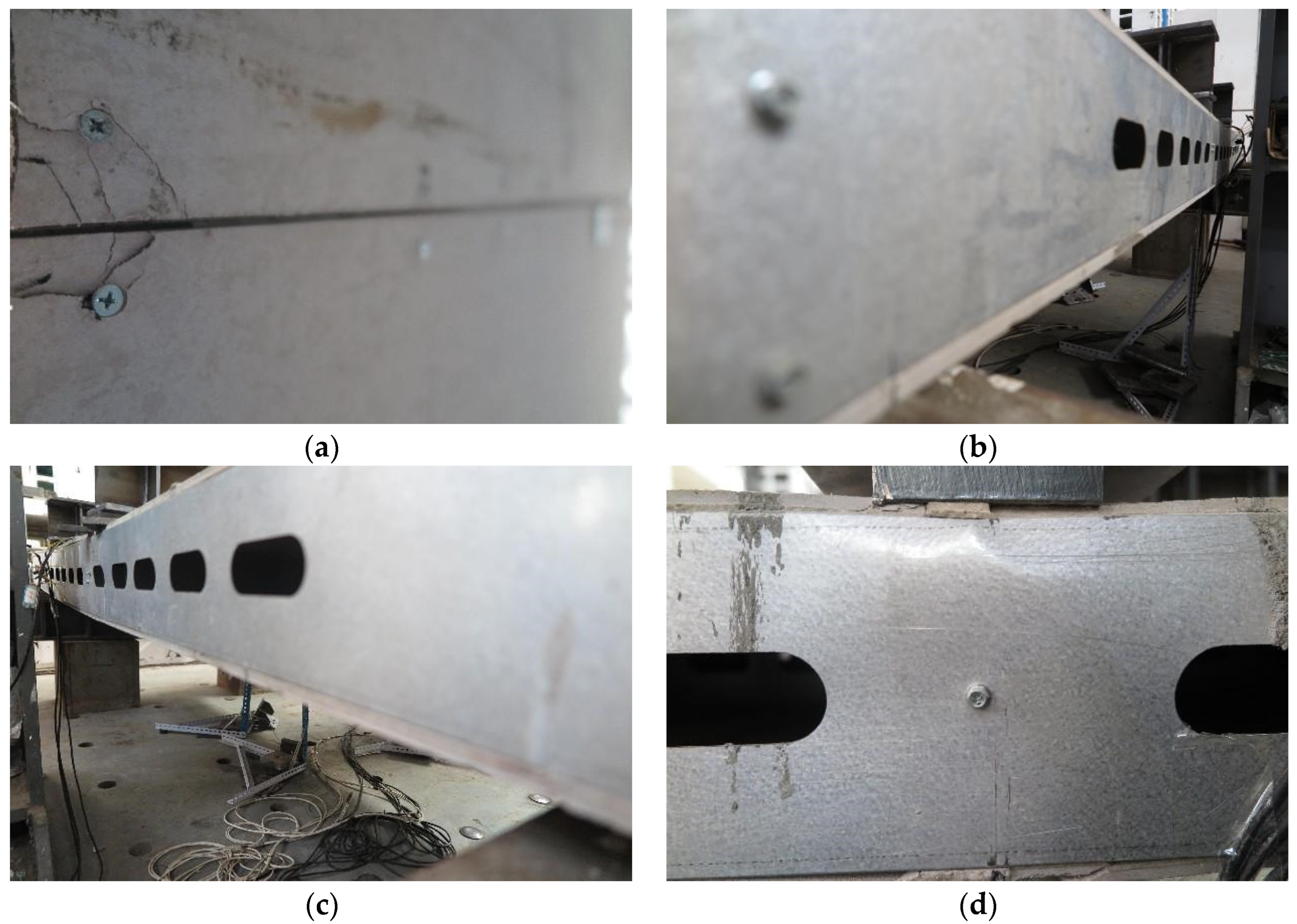
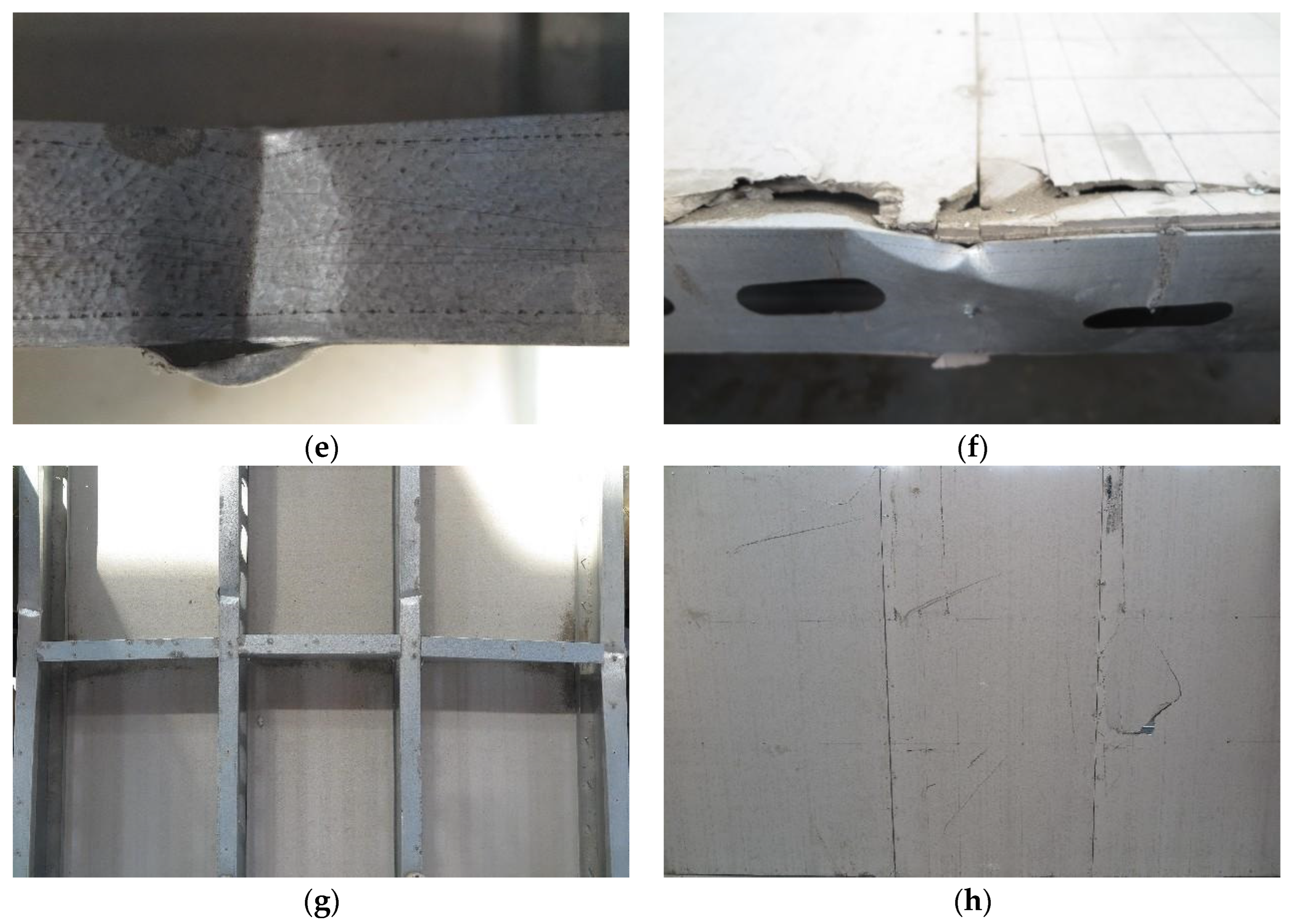
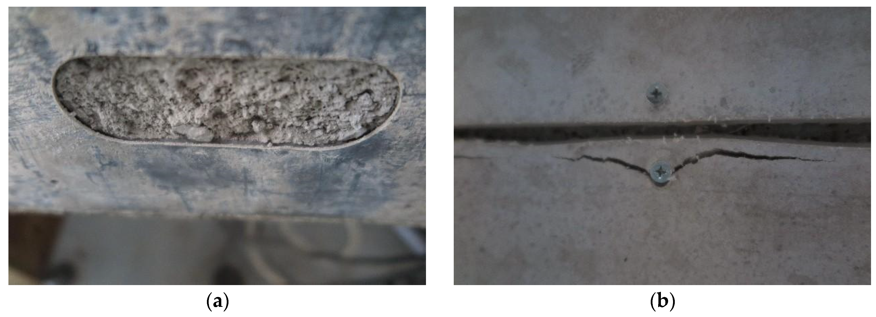
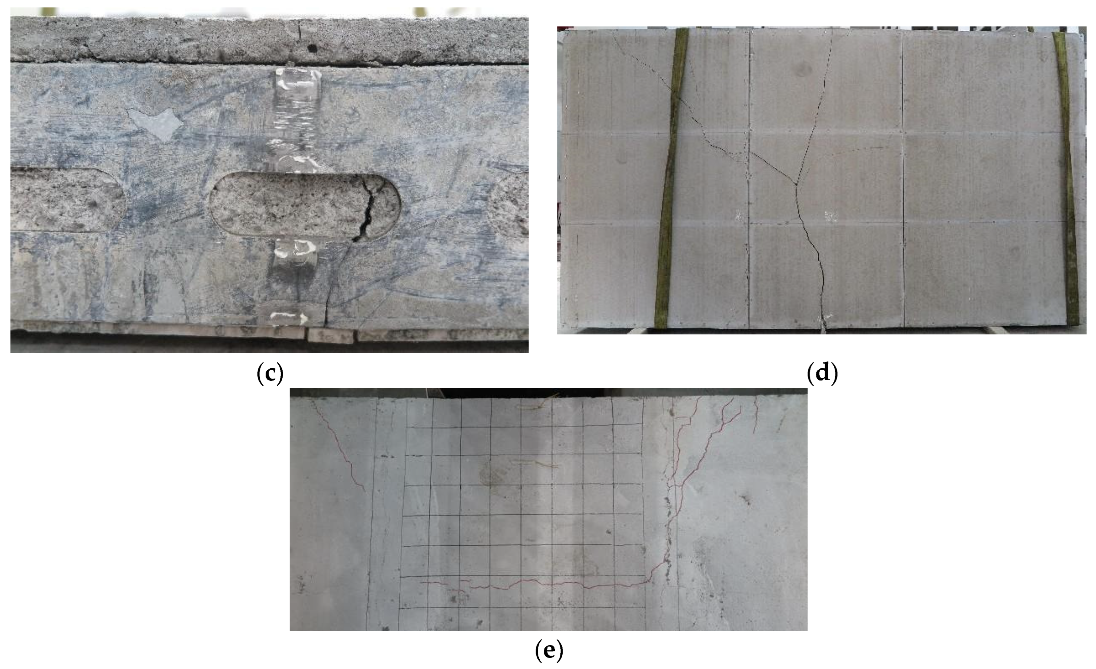
3.1. Failure Phenomena and Modes

3.1.1. CF-1

During the initial loading stage, there was no apparent experimental phenomenon. When loaded up to 30 kN, corner cracks appeared at the screw connections of the joint between the bottom CSBs (Figure 9a). At 42.6 kN, obvious local crippling occurred in the right CFS joist under the spreader beam, and the top CSB was crushed (Figure 9b), while the edge of the bottom CSB was pulled off (Figure 9c). At the same time, local failure occurred in the CSB at the mid-span top screw connections (Figure 9d). As the subsequent loading under displacement control progressed, the above damage and failures further intensified.
After the test, the top CSB was removed, and the deformation of the CFS joists was observed. It was found that the right joist broke the restraint of the single-sided CSB, causing web crippling. The middle joists were constrained by CSBs on both sides and had poor ductility due to the LQ550 grade and thin wall, which caused insufficient coordination of section deformation and resulted in tearing at the cold-formed position under the loading point (Figure 9e). Meanwhile, slight local buckling of the compression flange occurred at other sections (Figure 9f). The final failure forms of the cold-formed thin-walled steel joists and the bottom CSB are shown in Figure 9g,h, respectively. The failure mode of specimen CF-1 was web crippling and tearing of the steel joists under the loading point, which belongs to instability failure.

3.1.2. CF-2

During the initial loading stage, there was no apparent experimental phenomenon. When loaded up to 60 kN, cracks appeared around screw connections (Figure 10a); when loaded up to 80 kN, the cracks extended to both sides and connected (Figure 10b). At the same time, there were obvious tensile cracks in the bottom CSB (Figure 10c); when loaded up to 90 kN, the cracks further developed, and the bottom CSB gradually stopped working.
When loaded up to 130 kN, separation occurred between the flange of CFS joists and DSFC at the end position (Figure 10d); when loaded up to 138.3 kN, local buckling occurred on the left CFS joist outside the loading point (Figure 10e). As the subsequent loading under displacement control progressed, the left-side local buckling further intensified, and the foamed concrete under the flange was crushed, resulting in tearing at the cold-formed position (Figure 10f). Meanwhile, local buckling occurred on the right CFS joist under the loading point (Figure 10g). The natural bonding effect between the foamed concrete and joists was completely lost, causing bulging of the rim track (Figure 10h). The final failure forms of the foamed concrete and the bottom CSB are shown in Figure 10i,j, respectively.
The failure mode of specimen CF-2 was local buckling and tearing of the compression side of CFS joists, which belongs to instability failure.

3.1.3. CF-3

During the initial loading stage, there was no apparent experimental phenomenon. When loaded up to 40 kN, corner cracks appeared at the screw connections of the joint between the bottom CSBs (Figure 11a). When loaded up to 50 kN, elastic buckling deformation occurred throughout the entire length of the CFS joists (Figure 11b); when loaded up to 60 kN, the buckling deformation intensified (Figure 11c).
When loaded up to 64.8 kN, local crippling occurred under the loading point of the CFS joist (Figure 11d). As the subsequent loading under displacement control progressed, the web crippling further intensified, resulting in the tearing of the CFS at the cold-formed position (Figure 11e) and crushing of the CSB under the spreader beam (Figure 11f). The final failure forms of the cold-formed thin-walled steel joists and the bottom CSB are shown in Figure 11g,h, respectively.
The failure mode of specimen CF-3 was web crippling and tearing of the steel joists under the loading point, which is the same as specimen CF-1 and belongs to instability failure.

3.1.4. CF-4

During the initial loading stage, there was no apparent experimental phenomenon. When loaded up to 70 kN, there was an obvious separation between the web of the CFS and foamed concrete (Figure 12a); when loaded up to 100 kN, two joint cracks appeared in the bottom CSB, and cracks around screws were observed (Figure 12b).
When loaded up to 143.6 kN, the section from the bottom flange to the hole edge of the right-side CFS joist at the mid-span position broke with a sudden “bang” sound (Figure 12c). Correspondingly, the upper web had slight outward bulging, and the lower foamed concrete had obvious tensile cracks (Figure 12c). At the same time, the bottom CSB panel broke completely, with the main crack forming a “Y” shape (Figure 12d). It should be noted that due to the poor ductility of the LQ550 grade cold-formed thin-walled steel, uniform distribution of the load cannot be achieved through section plasticity development, resulting in only one-sided CFS joist breaking, tilting of the composite floor, and arched cracks appearing on the top surface (Figure 12e).
The failure mode of the specimen CF-4 was tensile fracture of the CFS joists at the mid-span, which belongs to strength failure and also exhibits obvious brittle failure characteristics.

3.1.5. Comparison and Discussion

The experimental results indicated that the failure modes of the CFS composite floors were local buckling at the top flange for specimens without holes and tensile failure at the bottom flange for specimens with holes, respectively, which differed from the web crippling observed in non-composite floors. The reasons why foamed concrete improved the flexural behavior of composite floors result from two aspects. The first is the compression effect of foamed concrete, while the second is the restraining effect. For specimens without holes, the tensile capacity of the bottom flange was greater than the buckling capacity of the compressed flange. For specimens with holes, the weakening of the cross-section led to the fracture of the bottom flange before the buckling of the compression flange, and its failure mode was similar to that of a reinforced concrete slab.

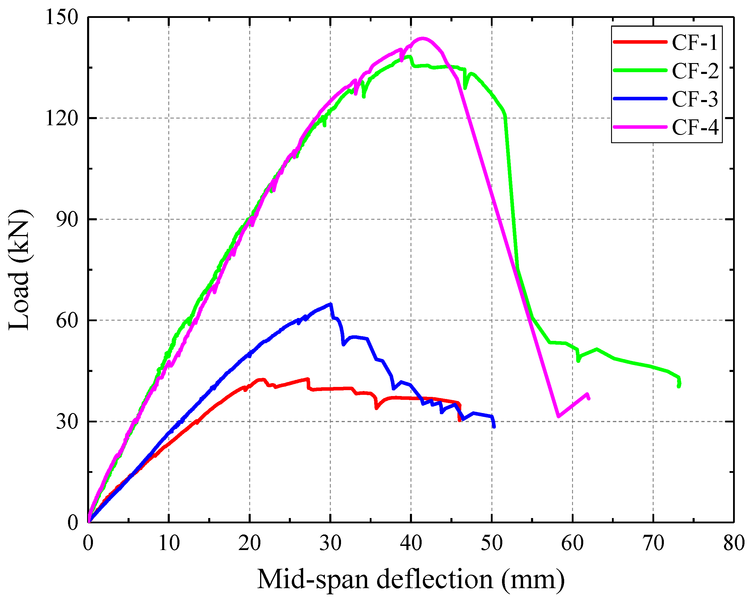
3.2. Load vs. Mid-Span Deflection Curves

The relations between the load and mid-span deflection of composite floors are shown in Figure 13. Several important parameters that merit attention are summarized and listed in Table 7, where the slope K at the allowable deflection L/250 [24] is defined as the flexural stiffness, and the corresponding load F250 is defined as the normal use load. In addition, the peak load is represented by Fp, and the corresponding deflection is represented by Δp. Based on the comparison of the load–deflection curves and characteristic parameters for each specimen, the following conclusions can be drawn:
(1)
The introduction of foamed concrete filling significantly enhanced the flexural stiffness and ultimate capacity of the floor. The flexural stiffness K increased by 117.6% and 73.6% for the specimens without holes and with holes, respectively, while Fp increased by 224.9% and 121.8%, respectively.
(2)
The specimens without holes (CF-1 and CF-2) displayed a more gradual decrease in bearing capacity after reaching the peak load, indicating better ductility. For specimen CF-2, the foamed concrete was compressed and compacted after reaching the peak load, which showed good ductility, and the load dropped sharply until the compression strain was too large and the CFS buckled and failed.
(3)
The presence of holes increased the ultimate capacity of the composite floor. For the specimens without foamed concrete filling (CF-1 and CF-3), Fp increased significantly by up to 52.2%. In general, the presence of holes weakens the cross-section of the CFS joists, reducing their capacity regardless of whether the final failure mode is local buckling or web crippling under the loading point. However, due to the high strength and poor ductility of the LQ550 grade cold-formed thin-walled steel used in this study, the deformation of CFS sections without holes was limited, and a tearing failure occurred at the cold-formed position before the full development of deformation. For the specimens infilled with foamed concrete (CF-2 and CF-4), Fp only increased by 3.9%. The presence of holes improved the bond–slip behavior between foamed concrete and CFS, increasing the degree of composite action and making better use of the compression strength of the foamed concrete. However, the presence of holes also weakened the web section, causing a tensile fracture of the steel joist from the bottom flange to the hole edge, resulting in a strength failure. Consequently, the impact of holes on the ultimate capacity of specimens infilled with foamed concrete was not significant.

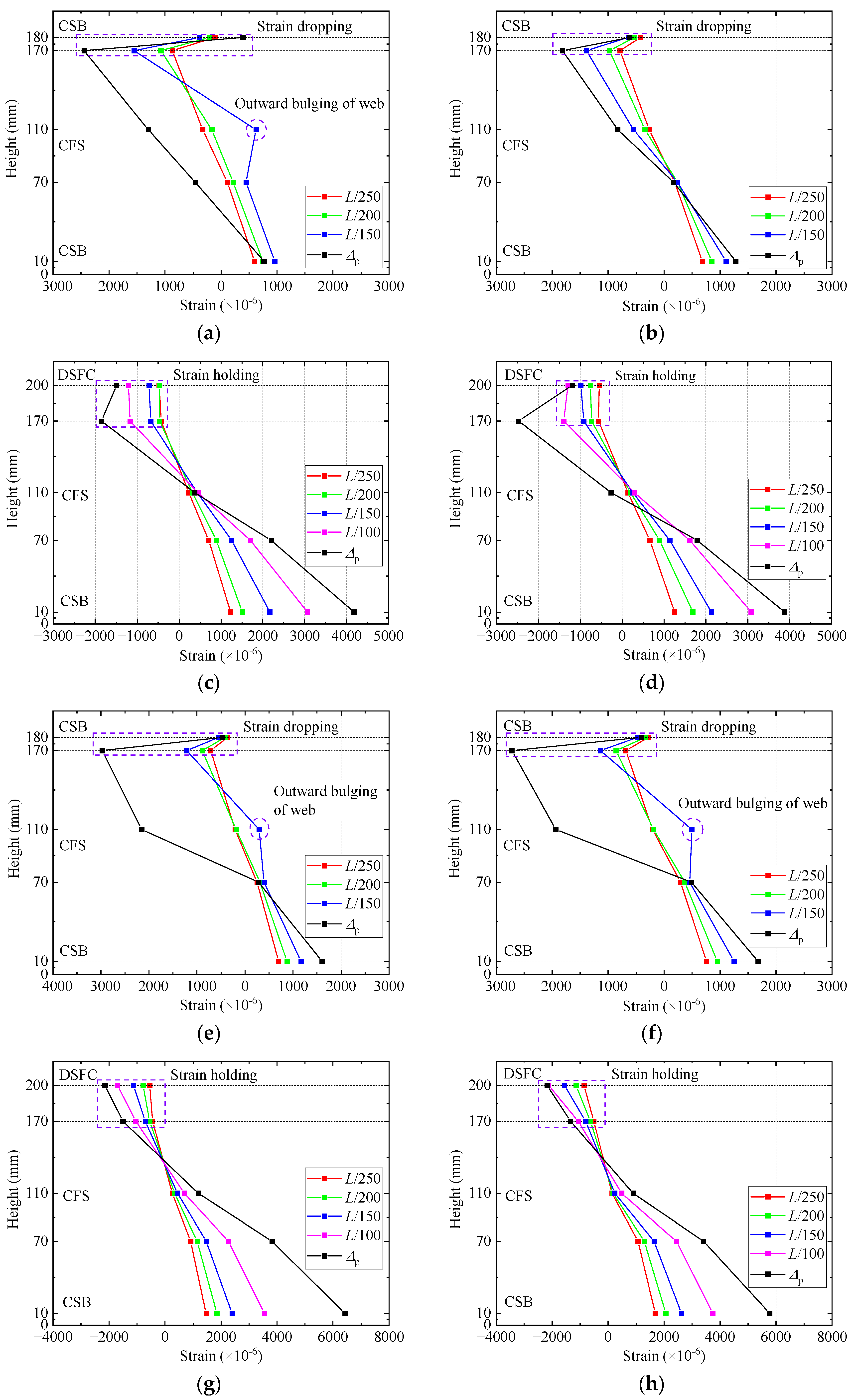
3.3. Strain Distribution at Mid-Span Section

The strain distribution of the side sections at mid-span for each specimen is summarized in Figure 14. The following conclusions can be drawn by observing the mid-span strain distribution:
(1)
Foamed concrete was effective in constraining the buckling deformation of cold-formed steel. For the specimens without foamed concrete filling (CF-1 and CF-3), the CFS satisfied the plane section assumption during the initial loading stage (Δ = L/250; Δ = L/200). As the load approached the ultimate capacity (Δ = L/150), abnormal tensile strains occurred at the height of 110 mm due to local buckling deformation that caused outward bulging. When load reached the peak (Δ = Δp), very large compressive strains occurred at the height of 110–170 mm due to the web crippling failure. For the specimens infilled with foamed concrete (CF-2 and CF-4), the foamed concrete prevented web crippling failure and effectively constrained the buckling deformation of CFS joists throughout the entire length, so that the CFS satisfied the plane section assumption during the entire loading process.
(2)
Self-drilling screws had difficulty in achieving effective load transfer and coordinated deformation between the CSB and CFS. By comparing the strains at the CFS web (height of 170 mm) and the top surface of the CSB (height of 180 mm) for specimens CF-1 and CF-3, it can be found that as the load increased, the compressive strain of the CFS kept increasing, while the compressive strain of the CSB remained almost unchanged at a low level. Instead, local damage occurred at the stress concentration point where the self-drilling screws were connected to the CSB. This indicated that self-drilling screw connections struggled to achieve effective load transfer and coordinated deformation between the CSB and CFS.
(3)
Partial composite action was achieved by the bonding effect between foamed concrete and CFS. By comparing the strains at the CFS web (height of 170 mm) and the top layer of the foamed concrete (height of 200 mm) for specimens CF-2 and CF-4, it can be found that as the load increased, the compressive strain of the CFS and the foamed concrete both kept increasing. For the specimen without holes (CF-2), the strain growth of the foamed concrete was relatively low, and only partial coordinated deformation was achieved. Moreover, the degree of composite action significantly decreased in the later loading stage due to the separation between the foamed concrete and CFS. For the specimen with holes (CF-4), the enhancement from the bond–slip behavior under holes resulted in a higher growth rate in the foamed concrete strain throughout the entire loading process, achieving fully coordinated deformation, and the section basically satisfied the plane section assumption.
(4)
The strain distribution on the left and right sides of the CF-1 specimen was significantly different, which is consistent with its failure mode of only right-side crippling and buckling of the CFS joist.

4. Nonlinear Finite Element Analysis

4.1. Finite Element Modeling

In this study, three-dimensional nonlinear finite element (FE) models of specimens CF-2 and CF-4 were established by using the software ABAQUS to conduct intensive research on the flexural behavior of CFS composite floor infilled with DSFC, while specimens CF-1 and CF-3 were not under consideration due to the difficulty in considering the impact of tearing damage. This model only consisted of CFS framing and DSFC, while, owing to the negligible structural performance, CSB, steel wire meshes, and self-drilling screws were omitted to improve computing efficiency. CFS framing was simulated by the four-node shell element (S4R) due to the negligible effect in the thickness direction compared to the whole plane, while DSFC was simulated by the eight-node solid element (C3D8R). It is best to be an integer multiple of the mesh size of the embedded region for the mesh size of the host region to achieve reliable computational accuracy and efficiency. Therefore, the mesh size of the CFS framing and DSFC were both set as 30 mm.
The material properties adopted in the FE model were obtained from the material test results discussed previously. The isotropic elastic–plastic material model and bi-linear constitutive model were adopted on CFS. The yield strength, elastic modulus, and Poisson’s ratio of CFS were 594.36 N/mm2, 2.12 × 10⁵ N/mm2 and 0.3, respectively. A ductile damage model was applied to simulate the response of CFS. Moreover, the yield strength and elastic modulus of the DSFC were 4.80 N/mm2 and 3243.3 N/mm2, respectively. The Concrete Damaged Plasticity (CDP) model available in ABAQUS was used to simulate the response of DSFC. The relevant parameters are referred to [25] and listed in Table 8.
The embedded element technique was used to model the bonding contact between CFS and DSFC. The simply supported boundary conditions were adopted by restraining the corresponding displacements of the rim track bottom flange in the x, y, and z directions at one support, and restraining the displacements in the y and z directions at the other support. In addition, two rigid plates coupled by a reference point were built to apply load controlled by displacement to zones under the spreader beams, and a general contact interaction procedure was used with normal behavior (“hard” formulation) to avoid intrusion between units. Figure 15 illustrated the details of the FE model.

4.2. Verification of Finite Element Model

Load–deflection curves obtained from tests and simulations are presented in Figure 16. The simulated ultimate capacity of specimens CF-2 and CF-4 are 136.97 kN and 138.28 kN, respectively, exhibiting a remarkable agreement with test results of 138.25 kN and 143.64 kN with the error of 0.9% and 3.7%, respectively. Moreover, the flexural stiffness of FE models is basically consistent with the experimental results within the error of 4.0%. Significant disparities between the simulation and experimental results in the descent section of load–deflection curves are revealed in Figure 16, and the simulation results show stronger ductility with a slow dropping because the actual failure modes of the specimens CF-2 and CF-4 involve the large deformation and fracture, which need to define more complex parameters to simulate the removal of failed elements. However, the descent stage is not the point of this study, so it is unnecessary to increase modeling difficulty and computational expense.
Stress distribution contours and comparisons with experimental phenomena are presented in Figure 17. Although the buckling deformation or fracture of the CFS is not demonstrated, the stress at the failure position has reached the ultimate value, which indirectly verifies that the failure mode of the simulation is consistent with tests.

4.3. Parametric Analyses

To explore the effects of material and geometrical parameters on the flexural behavior of CFS composite floor, parametric studies were conducted by FE modeling. In this parametric study, the CFS joist thickness (t), foamed concrete strength (fc), and hole spacing (s) were focused on. The flexural stiffness K and ultimate capacity Fp were analyzed and compared. It is worth noting that the change in density caused by the strength change in foamed concrete was not considered in this study, because of the uncertainty of the density–strength relationship.

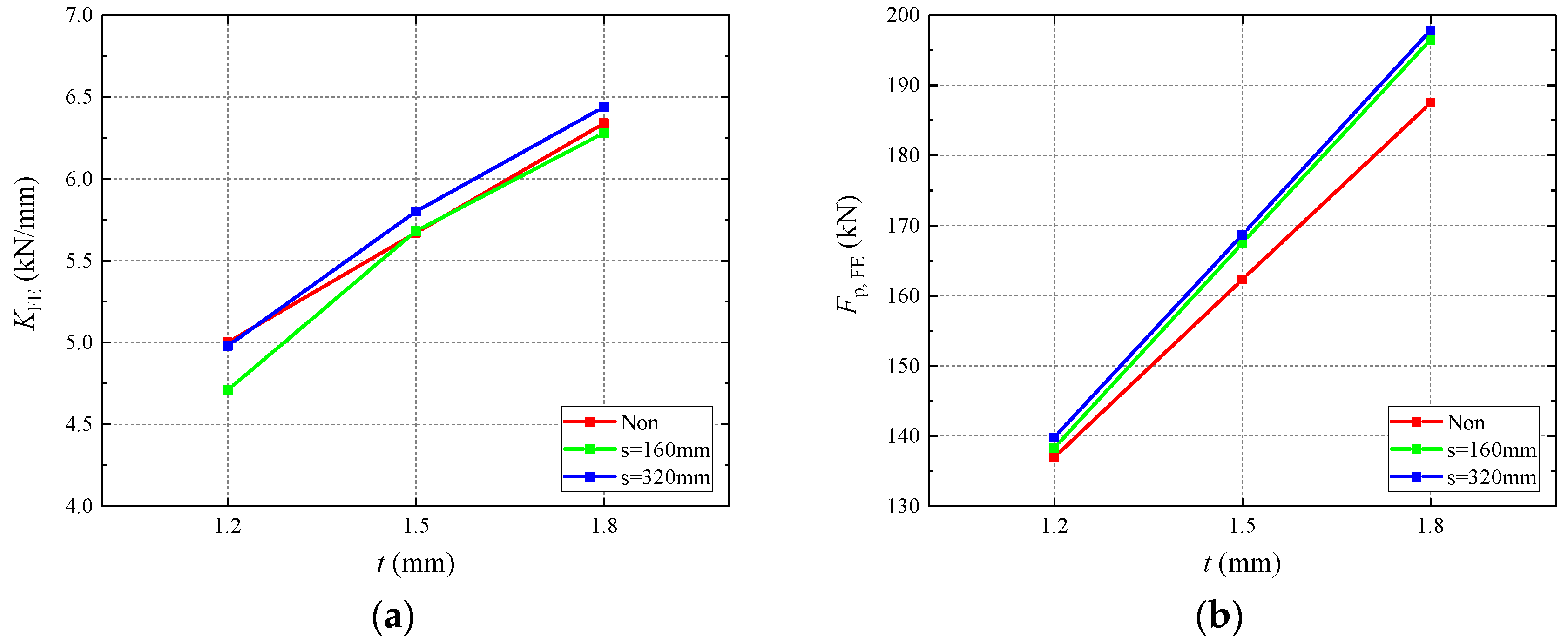
4.3.1. Influence of CFS Thickness

The flexural behavior of the composite floor associated with the variation in the CFS thickness, as obtained from the FE modeling, is presented in Table 9 and Figure 18. When the CFS thickness increased from 1.2 to 1.8 mm, the corresponding enhancements of all specimens were nearly 30% for flexural stiffness and 40% for ultimate capacity, respectively. The increase in the thickness resulted in a significant improvement in the flexural stiffness and ultimate capacity of the composite floors. For cold-formed thin-walled steel, there was a very complex nonlinear relationship between thickness and effective section area. However, due to the adequate constraints of foamed concrete, full section efficiency was achieved, so that a clear linear relationship between thickness and flexural behavior was observed.

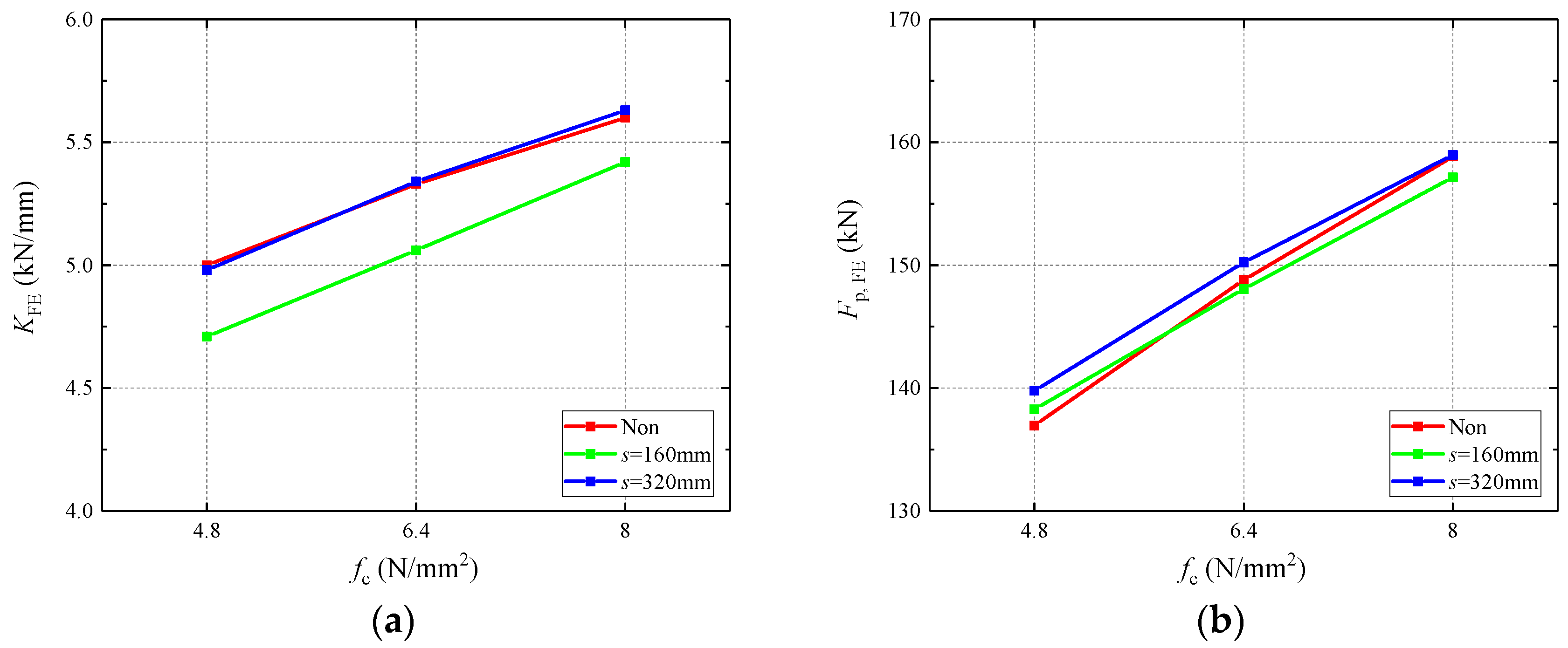
4.3.2. Influence of Foamed Concrete Strength

As indicated in Table 9 and Figure 19, the increase in the strength of foamed concrete resulted in improvements in both the stiffness and flexural capacity of the composite floor. The improvement in foamed concrete strength made the neutral axis move upward, increased the modulus of the flexural section, and improved the flexural behavior; on the other hand, it also improved the restraint effect on the local buckling of CFS joists. Regardless of the hole spacing, both the flexural stiffness and ultimate capacity were enhanced by nearly 15% when the foamed concrete strength increased from 4.8 to 8.0 kN/mm2.

4.3.3. Influence of Hole Spacing

To investigate the influence of hole spacing on the flexural behavior of composite floors, the results obtained from the FE modeling are presented in Table 9 and Figure 18 and Figure 19. Generally, the flexural behavior of CFS joists with un-stiffened holes will be greatly weakened compared to the joists without holes, due to the reduction in web stability [26,27,28,29]. In this study, the influence of hole spacing on flexural behavior was not significant on the whole. The holes enhanced the bond–slip behavior of the interface between the CFS and foamed concrete but weakened the section and changed the failure mode.

5. Conclusions

In this paper, the experimental investigation on the four full-scale specimens to determine the flexural behavior of cold-formed steel composite floors infilled with desert sand foamed concrete was presented. Then, the finite element models of the composite floor were established and validated with the test results followed by parametric analyses on CFS thickness, foamed concrete strength, and hole spacing. Based on the experimental and numerical results, the following conclusions were obtained:
(1)
For specimens without foamed concrete filling, the failure mode was web crippling of cold-formed thin-walled steel joists under concentrated loads. The presence of holes weakened the section stiffness, allowing the deformation of LQ550 steel to fully develop. For specimens infilled with foamed concrete, the presence of holes changed the failure mode from tensile fracture to local buckling of CFS and crushing of constrained foamed concrete.
(2)
Foamed concrete resisted compression in the compression zone and effectively constrained the buckling deformation of cold-formed thin-walled steel to improve the bearing capacity and stiffness of the composite floor.
(3)
Self-drilling screw connections struggled to achieve effective load transfer and coordinated deformation between CSB and CFS. The bonding effect between DSFC and CFS achieved partial composite action, and the degree of composite action increased with the improvement in the bond–slip behavior from holes.
(4)
The flexural behavior was improved with the increase in CFS thickness and foamed concrete strength. The impact of the holes was not obvious for specimens infilled with holes.

6. Future work

Based on the current research in this paper, it was found that foamed concrete can effectively improve the flexural behavior of the composite floor, because of the compression and restraint effects. Next, how to quantitatively consider the contribution of these two effects to the flexural capacity will be the focus of future work, including the estimate of the degree of composite action and the rectification of the effective width of compression plates. The final aim is to obtain a reliable design method for CFS composite floor infilled with foamed concrete.

Author Contributions

Writing—original draft, B.Y.; Investigation, Y.S.; Supervision, W.W.; Formal analysis, Q.W.; Validation, Z.H. All authors have read and agreed to the published version of the manuscript.

Funding

This research was funded by Guiyang Engineering Corporation Limited of Power China grant number [YJZD2019-01].

Data Availability Statement

The data presented in this study are available on request from the corresponding author.

Conflicts of Interest

The authors declare no conflict of interest.

References

  1. Hanaor, A. Tests of composite beams with cold-formed sections. J. Constr. Steel Res. 2000, 54, 245–264. [Google Scholar] [CrossRef]
  2. Hosseinpour, M.; Zeynalian, M.; Ataei, A.; Daei, M. An experimental study on structural performance of U-shaped shear connector in composite cold-formed steel floor joists. Eng. Struct. 2021, 249, 113379. [Google Scholar] [CrossRef]
  3. Hosseinpour, M.; Zeynalian, M.; Ataei, A.; Daei, M. Push-out tests on bolted shear connectors in composite cold-formed steel beams. Thin-Walled Struct. 2021, 164, 107831. [Google Scholar] [CrossRef]
  4. Hosseinpour, M.; Zeynalian, M.; Daei, M.; Ataei, A. Numerical study on behavior of bolted shear connector used in composite cold-formed steel beams. Thin-Walled Struct. 2022, 177, 109377. [Google Scholar] [CrossRef]
  5. Hsu, C.-T.T.; Punurai, S.; Punurai, W.; Majdi, Y. New composite beams having cold-formed steel joists and concrete slab. Eng. Struct. 2014, 71, 187–200. [Google Scholar] [CrossRef]
  6. Zhang, Z.; Wang, J.; Xiao, Y.; Wang, W. Experimental and analytical assessments on flexural behaviour of CTLST composite beams. Thin-Walled Struct. 2019, 138, 15–31. [Google Scholar] [CrossRef]
  7. Wang, J.; Wang, W.; Xiao, Y.; Guo, L. Cyclic behavior tests and evaluation of CFS truss composite floors. J. Build. Eng. 2020, 35, 101974. [Google Scholar] [CrossRef]
  8. Lakkavalli, B.S.; Liu, Y. Experimental study of composite cold-formed steel C-section floor joists. J. Constr. Steel Res. 2006, 62, 995–1006. [Google Scholar] [CrossRef]
  9. Güldür, H.; Baran, E.; Topkaya, C. Experimental and numerical analysis of cold-formed steel floor trusses with concrete filled compression chord. Eng. Struct. 2021, 234, 111813. [Google Scholar] [CrossRef]
  10. Xu, L.; Tangorra, F. Experimental investigation of lightweight residential floors supported by cold-formed steel C-shape joists. J. Constr. Steel Res. 2007, 63, 422–435. [Google Scholar] [CrossRef]
  11. Zhou, X.; Shi, Y.; Xu, L.; Yao, X.; Wang, W. A simplified method to evaluate the flexural capacity of lightweight cold-formed steel floor system with oriented strand board subfloor. Thin-Walled Struct. 2018, 134, 40–51. [Google Scholar] [CrossRef]
  12. Kyvelou, P.; Gardner, L.; Nethercot, D.A. Composite Action Between Cold-Formed Steel Beams and Wood-Based Floorboards. Int. J. Struct. Stab. Dyn. 2015, 15, 1540029. [Google Scholar] [CrossRef]
  13. Li, Y.; Shan, W.; Shen, H.; Zhang, Z.-W.; Liu, J. Bending resistance of I-section bamboo–steel composite beams utilizing adhesive bonding. Thin-Walled Struct. 2015, 89, 17–24. [Google Scholar] [CrossRef]
  14. Tian, L.-M.; Kou, Y.-F.; Hao, J.-P.; Zhao, L.-W. Flexural performance of a lightweight composite floor comprising cold-formed steel trusses and a composite mortar slab. Thin-Walled Struct. 2019, 144, 106361. [Google Scholar] [CrossRef]
  15. Shi, Y.; Yang, K.; Guan, Y.; Yao, X.; Xu, L.; Zhang, H. The flexural behavior of cold-formed steel composite beams. Eng. Struct. 2020, 218, 110819. [Google Scholar] [CrossRef]
  16. Guettala, S.; Mezghiche, B. Compressive strength and hydration with age of cement pastes containing dune sand powder. Constr. Build. Mater. 2011, 25, 1263–1269. [Google Scholar] [CrossRef]
  17. Luo, F.J.; He, L.; Pan, Z.; Duan, W.H.; Zhao, X.L.; Collins, F. Effect of very fine particles on workability and strength of concrete made with dune sand. Constr. Build. Mater. 2013, 47, 131–137. [Google Scholar] [CrossRef]
  18. Bouziani, T. Assessment of fresh properties and compressive strength of self-compacting concrete made with different sand types by mixture design modelling approach. Constr. Build. Mater. 2013, 49, 308–314. [Google Scholar] [CrossRef]
  19. Yan, W.; Wu, G.; Dong, Z. Optimization of the mix proportion for desert sand concrete based on a statistical model. Constr. Build. Mater. 2019, 226, 469–482. [Google Scholar] [CrossRef]
  20. Zhang, M.; Zhu, X.; Shi, J.; Liu, B.; He, Z.; Liang, C. Utilization of desert sand in the production of sustainable cement-based materials: A critical review. Constr. Build. Mater. 2022, 327, 127014. [Google Scholar] [CrossRef]
  21. Shi, Z. Green manufacturing of silicate materials using desert sand as a raw-material resource. Constr. Build. Mater. 2022, 338, 127539. [Google Scholar] [CrossRef]
  22. GB/T 228-2021; Metallic Materials-Tensile Testing at Ambient Temperature. China Architecture & Building Press: Beijing, China, 2021. (In Chinese)
  23. JG/T 266-2011; Foamed Concrete. Standards Press of China: Beijing, China, 2011. (In Chinese)
  24. JGJ/T 421-2018; Technical Standard for Cold-Formed Thin-Walled Steel Multi-Storey Residential Buildings. China Architecture & Building Press: Beijing, China, 2018. (In Chinese)
  25. Dai, S.; Zuo, Y.; Zhao, X.; Li, P. Research on effect of axial compression ratio on lightweight steel-foam concrete shear wall. Earthq. Resist. Eng. Retrofit. 2021, 43, 32–36. (In Chinese) [Google Scholar]
  26. Yu, C. Cold-formed steel flexural member with edge stiffened holes: Behavior, optimization, and design. J. Constr. Steel Res. 2012, 71, 210–218. [Google Scholar] [CrossRef]
  27. Zhao, J.; Sun, K.; Yu, C.; Wang, J. Tests and direct strength design on cold-formed steel channel beams with web holes. Eng. Struct. 2019, 184, 434–446. [Google Scholar] [CrossRef]
  28. Chen, B.; Roy, K.; Uzzaman, A.; Lim, J.B. Moment capacity of cold-formed channel beams with edge-stiffened web holes, un-stiffened web holes and plain webs. Thin-Walled Struct. 2020, 157, 107070. [Google Scholar] [CrossRef]
  29. Chen, B.; Roy, K.; Fang, Z.; Uzzaman, A.; Chi, Y.; Lim, J.B. Web crippling capacity of fastened cold-formed steel channels with edge-stiffened web holes, un-stiffened web holes and plain webs under two-flange loading. Thin-Walled Struct. 2021, 163, 107666. [Google Scholar] [CrossRef]
Figure 1. General configuration of CFS framing (unit: mm).
Buildings 13 01217 g001
Figure 2. Connection details (unit: mm). (a) Web stiffener at each end of the joists; (b) lateral bracing at the trisection point.
Buildings 13 01217 g002
Figure 3. Layouts of the CSBs and self-drilling screws (unit: mm).
Buildings 13 01217 g003
Figure 4. Section details of specimens (unit: mm). (a) CF-1 and CF-3; (b) CF-2 and CF-4.
Buildings 13 01217 g004
Figure 5. Material properties test. (a) Compression test; (b) tensile test.
Buildings 13 01217 g005
Figure 6. Stress–strain curves of LQ550 CFS.
Buildings 13 01217 g006
Figure 7. Test set-up. (a) Front view; (b) details.
Buildings 13 01217 g007aBuildings 13 01217 g007b
Figure 8. Layout of transducers (unit: mm). (a) LVDTs; (b) strain gauges.
Buildings 13 01217 g008
Figure 9. Failure phenomena of CF-1; (a) Corner cracks; (b) web crippling and CSB crushing; (c) edge fracture; (d) connection failure; (e) tearing; (f) local buckling; (g) failure form of CFS frame; (h) failure form of bottom CSB.
Buildings 13 01217 g009aBuildings 13 01217 g009b
Figure 10. Failure phenomena of CF-2; (a) Cracks around screws; (b) extension of cracks; (c) joint cracks; (d) separation between CFS and DSFC; (e) local buckling (left-side); (f) tearing and crushing of DSFC under flange; (g) local buckling (right-side); (h) bulging of rim track; (i) failure form of DSFC; (j) failure form of bottom CSB.
Buildings 13 01217 g010aBuildings 13 01217 g010b
Figure 11. Failure phenomena of CF-3; (a) Corner cracks; (b) local buckling (left-side); (c) local buckling (right-side); (d) web crippling; (e) tearing; (f) web crippling and CSB crushing; (g) failure form of CFS frame; (h) failure form of bottom CSB.
Buildings 13 01217 g011aBuildings 13 01217 g011b
Figure 12. Failure phenomena of CF-4; (a) separation between CFS and DSFC; (b) cracks around screws; (c) tensile fracture of CFS and DSFC; (d) joint cracks; (e) arched cracks.
Buildings 13 01217 g012aBuildings 13 01217 g012b
Figure 13. Load–deflection curves.
Buildings 13 01217 g013
Figure 14. Strain distribution at mid-span; (a) CF-1 (right-side); (b) CF-1 (left-side); (c) CF-2 (right-side); (d) CF-2 (left-side); (e) CF-3 (right-side); (f) CF-3 (left-side); (g) CF-4 (right-side); (h) CF-4 (left-side).
Buildings 13 01217 g014
Figure 15. Details of the FE model.
Buildings 13 01217 g015
Figure 16. Comparison of load–deflection curves; (a) CF-2; (b) CF-4.
Buildings 13 01217 g016
Figure 17. Stress distribution contours of the FE models (unit: MPa); (a) CF-2; (b) CF-4.
Buildings 13 01217 g017aBuildings 13 01217 g017b
Figure 18. Influence of CFS thickness and hole spacing; (a) KFEt; (b) Fp, FEt.
Buildings 13 01217 g018
Figure 19. Influence of foamed concrete strength and hole spacing; (a) KFEfc; (b) Fp, FEfc.
Buildings 13 01217 g019
Table 1. General information on the floor specimens.
SpecimenSpan (mm)Width (mm)Height (mm)Component
CF-132001800180CFS joists + CSBs
CF-2180CFS joists + CSBs + DSFC
CF-3200CFS joists with holes + CSBs
CF-4200CFS joists with holes + CSBs + DSFC
Table 2. Properties of the CFS.
Thickness (mm)Elastic Modulus (MPa)Yield Stress (MPa)Ultimate Stress (MPa)Elongation (%)
1.22.12 × 105594.36601.7516.1
Table 3. Gradation of desert sand.
Particle size (μm)600300150<150
Residue on sieve (%)24.423.449.23.0
Table 4. Mix proportion of foamed concrete.
Cement (g)Desert Sand (g)Water (g)Foam Volume (L)Water-Reducing Agents (g)Polypropylene Fiber (g)Water-Cement Ratio
45015012613.60.90.28
Table 5. Properties of the DSFC.
Density (kg·m−3)Compressive Strength (MPa)Elastic Modulus (MPa)
1042.04.803243.3
Table 6. Properties of the CSBs.
Thickness (mm)Density (g·cm−3)Flexural Strength (MPa)
10.01.3211.9
Table 7. Parameters summarized from test results.
SpecimenL/250 (mm)K (kN/mm)F250 (mm)Fp (kN)Δp (mm)
CF-1122.2727.3542.5527.22
CF-24.9459.33138.2539.77
CF-32.6131.4364.7630.06
CF-44.5354.45143.6441.50
Table 8. Parameters of the CDP model.
Dilation AngleFlow Potential Eccentricityfb0/fc0KViscosity Parameter
30°0.11.160.66670.0005
Note: fb0/fc0 = ratio of the initial equi-biaxial compressive yield stress to initial uniaxial compressive yield stress; K = the ratio of the second stress invariant on the tensile meridian.
Table 9. Parametric analyses.
SpecimenKFERK,tRK,fcFp,FERF,tRF,fc
CF-1.2t-4.8fc5.001.001.00136.971.001.00
CF-1.5t-4.8fc5.671.13\162.321.19\
CF-1.8t-4.8fc6.341.27\187.511.37\
CF-1.2t-6.4fc5.33\1.07148.80\1.09
CF-1.2t-8.0fc5.60\1.12158.85\1.16
CF-160s-1.2t-4.8fc4.711.001.00138.281.001.00
CF-160s-1.5t-4.8fc5.681.21\167.501.21\
CF-160s-1.8t-4.8fc6.281.33\196.521.42\
CF-160s-1.2t-6.4fc5.06\1.07148.06\1.07
CF-160s-1.2t-8.0fc5.42\1.15157.16\1.14
CF-320s-1.2t-4.8fc4.981.001.00139.781.001.00
CF-320s-1.5t-4.8fc5.801.16\168.721.21\
CF-320s-1.8t-4.8fc6.441.29\197.831.42\
CF-320s-1.2t-6.4fc5.34\1.07150.23\1.07
CF-320s-1.2t-8.0fc5.63\1.13158.98\1.14
Note: CF-160s-1.2t-4.8fc represents the specimen with a 160 mm hole spacing, 1.2 mm CFS thickness, and 4.8 N/mm2 foamed concrete strength. KFE is the predicted flexural stiffness from FE analysis. RK,t and RK,fc are the corresponding ratios considering the influence of thickness and foamed concrete strength, respectively. Fp,FE is the predicted ultimate capacity from FE analysis. RF,t and RF,fc are the corresponding ratios considering the influence of thickness and foamed concrete strength, respectively.
Disclaimer/Publisher’s Note: The statements, opinions and data contained in all publications are solely those of the individual author(s) and contributor(s) and not of MDPI and/or the editor(s). MDPI and/or the editor(s) disclaim responsibility for any injury to people or property resulting from any ideas, methods, instructions or products referred to in the content.

