Abstract
Virtual reality was investigated with various computational design approaches to improve users’ ability to communicate, share, and grasp the design’s requirements to better conceptualize ideas during various design and review stages. The study aims to show how computational design and virtual reality are utilized to forecast challenges, address design problems/limitations in a specific study space, and validate results. A case study of the main Architectural Engineering department building at the University of Sharjah (UoS) campus in Sharjah, United Arab Emirates, was considered. The study focused on indoor daylight intake, ventilation, functionality, user comfortability, structural integrity, coherency and consistency, and performance optimization as factors to further evaluate and aid in the selection process of the optimal design. Consequently, innovative computational design tools were used in the study’s methodology to assess offered alternatives, such as altering and fabricating the building’s skin to deal with the challenges described above and improving the selected room’s visual and environmental conditions, such as optimal daylighting and ensuring users’ comfortability. The users’ immersive experience resulted in more accurate visualization and navigation around the to-be-built environment, allowing for more significant analysis and comprehension that further validated the results obtained. The chosen case study thus demonstrated the potential for computational design, mixed reality techniques, and strategies to enable an efficient process that ultimately verifies approaches taken toward a much more optimal solution through better visualization and contextualizing.
1. Introduction
Designers see, act, and then re-observe, which enables better investigation, understanding, and appreciation of the site and concept growth when working in a visual medium [1]. During the conceptual design process, designers create design criteria that capture the essential elements of the given challenge and synthesize solutions that satisfy the initial needs [2]. To succeed in architecture, one needs to think critically, care about little details, and think creatively to undergo several options. These two mental processes must coexist and function simultaneously [3]. Additionally, designers and architects have experimented with several tools, methods, and processes that enhance their abilities and help them during the design process. For several years, conventional tools such as sketches were the visualization techniques for architects and designers. Generally, architecture is renowned for fostering concepts and ideas from discussion among designers. In several settings, including meetings and intellectual working groups or teams, idea exchange or sharing is a crucial component of group interaction. Therefore, incorporating technology made decision-making and idea exchange simple and available. As a result, the significance of technology was soon emphasized.
Integrating technology in architecture has also facilitated the creation of more sustainable and environmentally friendly buildings [3]. By using simulation software, architects can analyze the performance of a building’s energy systems and optimize them for maximum efficiency [4,5]. Therefore, Building Information Modeling (BIM) has also allowed for greater collaboration and coordination between the various parties involved in the construction process, resulting in more accurate and streamlined building designs [6,7]. Technology has revolutionized how architects and designers approach their work, providing them with new tools and methods to enhance their creativity and problem-solving abilities. Thus, technology will probably continue to change the world of architecture in ways that are still unimaginable as it evolves.
Optimization is crucial for achieving challenging design goals, especially those related to sustainability and building performance [6]. While exploration is necessary to discover viable solutions, utilizing different methods to identify optimal designs that surpass the “good enough” standard is essential. Recent advancements in form-finding design have expanded the optimization concept, allowing for a comprehensive assessment of buildings’ environmental and user behavior [7].
The article contributes to the following:
- Conducting a thorough literature review, and research background, including a case study of the University of Sharjah the Architectural Engineering Department (AED) building.
- Integrating virtual reality in the AEC industry for design and validation purposes.
- Utilizing computational design techniques to analyze and enhance the aesthetic appeal of a studio while maintaining consistency with existing design elements at the University of Sharjah.
- Additionally, the article discusses the various VR implementations and their validation.
1.1. Integration of Computational Design with Extended Realities
Integrating computational design with extended realities (XR) in architecture offers many possibilities and benefits. Computational design is a process that involves the use of algorithms and mathematical models to generate designs, while XR technologies encompass virtual reality (VR), augmented reality (AR), and mixed reality (MR) that merge virtual and real-world environments [8]. By integrating XR with computational design, architects and designers can better understand and visualize the design, making it easier to communicate ideas and collaborate with stakeholders. For example, AR can be used to overlay digital information onto a real-world environment, allowing architects to visualize how a design would look in its physical location [9]. Conversely, VR allows architects to create immersive environments that enable users to experience a design as if they were in space. This can help clients and stakeholders better understand a design before it is built, reducing the risk of costly changes during construction. MR, which sits between VR and AR, can provide real-time interaction between virtual and real-world environments, offering a unique opportunity for architects to explore and refine their designs. MR can also enable architects to incorporate real-world data, such as sunlight or wind patterns, into the design process [10]. In addition, computational design can help optimize designs for factors such as energy efficiency, structural stability, and cost-effectiveness. XR technologies can be used to visualize the impact of design decisions on these factors, making optimizing the design before construction easier [4]. Overall, integrating computational design with XR technologies offers architects and designers a powerful set of tools to visualize, refine, and optimize designs, leading to better outcomes and more efficient design processes. Generally, XR combines the actual world and the virtual environment simultaneously with differing degrees of immersion through various technologies. Hence, the virtuality continuum, which is a continuous scale ranging from totally virtual (i.e., virtuality) to completely real (i.e., reality), is depicted in Figure 1 and includes all conceivable combinations and sub-compositions of both actual and virtual environments.
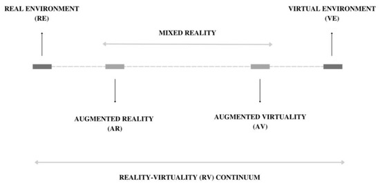
Figure 1.
Reality–virtuality continuum.
The integration of XR technologies in architecture significantly impacts the design process, particularly in terms of visualization and communication with stakeholders. While architects have 3D visualization skills, clients may only fully comprehend a building’s design using XR technologies. However, the advancement of XR technologies in architecture is still gradual and falls short of meeting the industry’s demand. VR, AR, and MR are three commonly used technologies that architects can utilize to present their ideas to clients. MR and AR, in particular, allow designers to interact with the model using a more expansive VR-related technology, providing context and links between parts and assemblies of a design [11,12]. XR technologies can also visualize and supervise the project more dynamically, simulating the project with the actual environment and resources. This can help reveal potentially hazardous consequences that can be avoided before construction [9,13]. Moreover, integrating computational design with extended realities can improve the application’s performance, as creating and modifying architecture with high-level editing operations that automatically fill in the relevant details require quick rendering and an easy input procedure [14]. Finally, stakeholder participation, design support, and design review can all be linked and implemented with XR technologies. As a result, it can be deduced that XR technology is primarily used during the project’s design phase [15].
As such, the integration of immersive technologies such as VR, AR, and MR in the design process is still in its early stages, but the potential benefits are numerous, such as:
- Enhanced Visualization: Immersive technologies provide designers with a realistic 3D view of the project, which helps them to better understand the space and how it will look once completed.
- Improved Communication: Immersive technologies allow designers to share their design concepts with clients and stakeholders more interactively and engagingly. This helps ensure everyone is on the same page and can contribute to the project’s success.
- Efficient Design Process: Immersive technologies help to streamline the design process by allowing designers to quickly identify any design flaws and make necessary modifications. This leads to a faster and more efficient design process.
- Increased Client Satisfaction: By utilizing immersive technologies, designers can create a more personalized experience for clients, increasing client satisfaction.
- Cost Savings: Immersive technologies help reduce the number of design revisions needed, leading to cost savings for the project.
- Safety: Immersive technologies can identify and mitigate potential safety hazards before construction begins, improving the project’s overall safety.
- Sustainability: Immersive technologies can be used to simulate and analyze the energy performance of a building, which can help to identify areas for improvement and make the project more sustainable.
Overall, integrating immersive technologies in the design process can enhance the design experience, improve collaboration and communication, and streamline the design process while reducing costs and improving safety and sustainability.
1.2. Importance of AR, VR, and MR Integration with Computational Design
The integration of AR, VR, and MR with computational design can have significant advantages in the field of architecture and design. These technologies provide a new level of interaction and visualization, enabling architects, designers, and clients to experience and understand designs in a more immersive and realistic way [16]. One of the most important advantages of integrating AR, VR, and MR with computational design is the ability to simulate and visualize designs in real-world contexts. This can help architects and designers identify potential issues and make necessary adjustments before the construction phase, saving time, money, and resources. Clients can also better understand and visualize the design, leading to improved communication and more accurate feedback. In addition, these technologies can allow for more efficient and streamlined design processes. For example, using VR or MR to review and make design changes can reduce the need for physical prototypes, which can be costly and time-consuming. Moreover, XR technologies can also enable remote collaboration between team members, regardless of location. Another advantage is the potential for enhanced creativity and exploration. AR, VR, and MR can provide new ways of exploring design options, allowing architects and designers to experiment with different ideas and possibilities without physical limitations. This can lead to more innovative and creative designs. Overall, integrating AR, VR, and MR with computational design can offer numerous benefits for the architecture and design industry, including improved communication, more efficient processes, enhanced creativity, and visualize designs better in real-world contexts.
1.3. Computational Design Simulation and Optimization
Typically, structures are planned with a range of constraints in mind, including the climate, culture, approach, available technology, etc. As a result, the design team will be constrained and hindered by the current design’s intricacy and the absence of computational models and tools, compelling them to settle on any solution they may find suitable. Additionally, this early emphasis may result in only partial design optimization solutions [17]. Usually, designers refine a concept into a design that meets the client’s needs while taking advantage of their surroundings. Otherwise, residents would have a combination of problems, such as economic difficulties related to discomfort from the heat and other elements that may impact the users’ experience negatively. Therefore, applying Architectural Design Optimization (ADO), which combines parametric design and building performance simulation, to develop a well-performing design solution may increase the AEC sectors’ material and energy efficiency [18].
Architects are eager to incorporate performance measures throughout the various building form generations and evaluations to produce a performance-based design. These performance metrics are effectively acquired using a computational design process that accelerates and limits the search. Computational design typically involves a mathematical and algorithmic approach with a predetermined set of parameters to be considered and modified [19]. In computational design, the designer is responsible for choosing the optimal strategy for dealing with the design based on the issue formulation, modeled relationships, and the optimization technique that should be used [20]. Overall, designers use computational tools to produce studies and discover educated hypotheses that help further ensure optimal design while allowing the designer to use arbitrary human design preferences. Architects greatly benefit from using parametric technologies to design and construct with exceptionally high standards and values [11]. Therefore, conceptual design optimization enables the testing and experimentation of many designs while enabling designers to take chances and increase the range of potential solutions. Since this is the case, incorporating the structure’s performance and fundamental requirements throughout the design process is a crucial component of the decision support framework that underpins modern high-performance architecture [21].
Yan et al. studied the possibility of generating topology-optimized structural designs as high-efficiency forms while preserving an elegant geometry [22]. Through the research, Yan et al. demonstrated how conventional topology optimization delivers a solution that maximizes structural performance as opposed to other design requirements, which may result in a resolution that contradicts particular architectural restrictions or conceptions. The article established an open working framework that gives the designer flexibility by fusing a well-known parametric modeling platform with structural analysis methods. Again, a study by Maksoud et al. addressed issues with solar radiation, thermal comfort, and visual comfort by creating an Islamic parametric elevation that provided the best possible environmental performance [23]. Through a medley of plugins and analyses, it was possible to obtain shadow analysis, wind diagrams, and solar radiation diagrams, which gave the necessary data on energy performance, precipitation, the sun’s path, solar radiation, and the impact of the building’s orientation. Afterward, multiple analyses were conducted, comparing the status of the corridor with the computational outcomes and finally arriving at an optimized solution while considering the design’s structure and keeping its overall concept and aesthetics.
1.4. Applications
Since building forms are impossible without representation, architecture and representation have always been utilized concurrently and in the same context. In Castelo-Branco and Leitão’s article, superior results were shown. The study suggested combining algorithmic design with virtual reality technology to allow several lifestyle changes while immersed in VR. The experiment was made possible by Khepri, an algorithmic tool, and Unity, a gaming engine, for the visual quality, lighting, shadows, and physics it creates. These features also made it possible to create and update the model frequently. In the first stage of the experiment, 21 people from various backgrounds worked on a small-scale project about an acoustic intervention on a classroom ceiling. The VR exercise allowed the projection’s arrangement to be changed on-demand by adding or removing attractor points that affect the grid with ripple patterns on the ceiling, which is comprised of wooden panels, as shown in Figure 2. The only requirements for the experiment’s participants were to take up a specific position within the model and follow verbal instructions. Alternation often took a few seconds to become apparent, but the total time varied among participants.
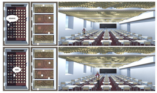
Figure 2.
Stage one of the experiment focuses on acoustic intervention on classroom ceiling [24].
In contrast, the alternate portion of the experiment reduced the subject to a total of 10, of which 6 were architectural practitioners with AD training, and 4 were MSc students in computer science. The objective was to use the algorithmic design in virtual reality (ADVR) approach to build an algorithmic description of a semi-random pagoda city from scratch, shown in Figure 3. This experiment should have only taken 20 min to complete; however, different individuals spent different amounts of time on it. Even though computational optimization was not a primary focus of either experiment, algorithmic design tools such as Khepri incorporate various backends for various design objectives, including analysis and optimization.
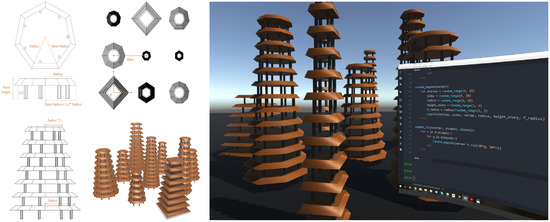
Figure 3.
Stage two of the experiment, where a semi-random pagoda city was built from scratch [24].
2. Research Background
2.1. Geographical Location
The approaches and procedures used to resolve the challenges and conflicts noticed were shaped by relating the research area to a broader scope, including but not limited to the land, climate, society, culture, heritage, and environment. The United Arab Emirates has a diverse landscape that includes a stony desert, coastal plains, marshes, and mountains devoid of water. The different sites, opulent resorts, unspoiled beaches, and other treasures typically draw tourists. However, most visitors are attracted to exploring all the historic locations whose architecture captures the history and culture of the country. It is well known that the United Arab Emirates saw an extraordinary period of growth, as evidenced by modern, international architecture, particularly in Dubai and Abu Dhabi. Thus, massive agriculture projects were carried out in the country’s desert terrain [25]. Despite the diversity of countries and ethnic backgrounds, the United Arab Emirates exhibits an impressive fusion of traditional practices and innovative technology. Moreover, the only emirate with territory on both the Arabian Gulf Coast and the Gulf of Oman is Sharjah, the third largest of the seven emirates. Sharjah is northwest–southwest orientated and is renowned for having warm, sunny weather all year round. Furthermore, Sharjah, where the case study will take place, shown in Figure 4, is notable for its rich architectural and cultural heritage.
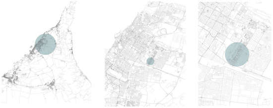
Figure 4.
Partial university plan visualizer that shows the location of M8 with respect to other departments.
2.2. Islamic Architecture and Decorative Elements
Islamic doctrine and ideology play a significant role in the origin of Islamic art and decorations [26]. More importantly, buildings’ facades typically reflected these distinctive Islamic features elegantly and precisely. For some evaluation and development, the structure of the ornamentation—which includes vegetal, geometrical, and figural elements, or even a mixture of two or more of the decorative elements—was often extremely considered. Additionally, ornamental themes and embellishments that reflected Islam’s heritage and foreign influences helped connect the architecture to a specific period of its history. Thus, Islamic geometrical patterns were frequently used to ornament architectural features and components such as doors, ceilings, walls, grilles, domes, and minarets [27]. Furthermore, Islamic motives and decorative ornaments are diverse and expressed in several ways and media. Among the most well-known adornments are Muqarnas, Mashrabiya, arabesque, ornate mosaic tiling, arches, pietra dura, jali, etc.
In the United Arab Emirates, notably in Sharjah, Islamic architecture and decorative features are prevalent. Architectural details, including arches, arabesques, complex ornamentation, and geometric Islamic motifs, may be seen all around the emirate. Nevertheless, structures still show off the integration of well-known Islamic architectural features such as Riwaqs, domes, and courtyards. For example, in modern mosques, minarets and domes are interpreted with a modernized twist that reflects the advancement of architecture and technology. Therefore, despite the fact that the synthesis of internationally recognized Islamic decorative motifs and culturally recognized decorative components often results in an unequaled aesthetic and coherence, some minor variations can still be seen. Nonetheless, regardless of the suggestions’ attempts to gently question Islamic architecture’s typicalness, fundamental Islamic architectural elements are still preserved.
Currently, parametric tools may help create and fabricate forms and ornaments modeled after Islamic-era architecture. In the case of Maksoud et al., an Islamic geometric pattern screen was parametrically designed by adjusting two parameters that controlled the porosity size and the gradient span, respectively [23]. Then, twelve of the infinitely many variations were selected and further examined regarding the performance. Additionally, the proper application of materials and technology simultaneously will enable decorations and decorative themes to transcend the static. According to Mitrache, modern façade-wide ornamental art is kinetic, kaleidoscopic, and reactive, which was made feasible by properly thought-out, computer-controlled algorithms [28]. The ability of computational design to precisely duplicate and develop patterns also makes it much easier to create complicated patterns, such as the ornate Islamic star.
2.3. Climate and Environment
Generally, the temperature near the shore of the United Arab Emirates is renowned for being hot and humid. However, people frequently encounter hotter and drier weather indoors, which is directly related to how uncomfortable the occupants are. In addition, the “northern” wind, which blows from the north to the northwest in midwinter and early summer, carries dust and sand. Given its desert environment, vegetation is sparse and severely constrained. However, the area has seen the planting of trees, which has improved the natural ecology and given a variety of species new habitats.
3. Case Study: Department of Architectural Engineering at University of Sharjah
In this research, the studio inspected is located on the ground floor level of the Architectural Engineering Department (AED), used by senior students from 8 a.m. to 5 p.m. However, this time frame can be extended until 7 o’clock as needed. The fact that this case study’s studio is the only studio available to seniors emphasizes the need to acquire a space that fosters collaboration among students and provides a comfortable environment for the numerous types of studies and model-making stages students must complete.
After thoroughly evaluating the senior studio’s current condition, this research aims to boost the studio’s overall performance through several improvements. Therefore, the main objective of this research is to ensure that the studio’s design is performance-optimized while still offering a high level of usability, comfortability, and productivity. Certainly, factors such as uniformity, aesthetics, and visual comfortability are all considered when designing and producing the geometrical computational advancements presented. Moreover, this research aims not only to create a better atmosphere that will facilitate a better environment for the students, thus enhancing their psychological and academic state, but also to create harmony with the outdoor area. The studio room of this study is located near the main campus, which requires special attention to how connectivity is promoted both visually and physically between the two buildings throughout the design.
Figure 5 shows the ground floor level of the AED building where the senior’s studio is clearly indicated and shown in relation to other facilities, offices, and studios that may also be located on the building’s ground level. Noticeably, the senior’s studio is oriented north, with two outer walls that face northeast and northwest, respectively. Furthermore, understanding how the studio’s orientation, exposure, and adaptability to the surrounding environment influenced the studio’s performance will aid in improving the methodology used to confirm the effectiveness of the proposed design strategy. Due to the studio’s two shared outer walls, it is easier to suggest options that will optimize the quantity of daylight that is brought inside and suggest methods and techniques that will also further impact the comfort of the students.
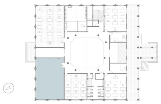
Figure 5.
Senior studio room location within the Architectural Engineering department (M8)–M8, ground floor.
3.1. Current State of the Studio
Preliminary information and data were gathered by examining the studio, which further highlighted the negative effects that seniors are currently dealing with. Determining these concerns’ importance reveals how ignoring them may ultimately have negative psychological and long-term health effects on the students. Therefore, it was necessary to conduct a thorough analysis to ascertain the current effects of variables such as wind, sun radiation, and sunlight intake on the senior studio.
Initially, the annual sun path diagram for January through December, shown in Figure 6, was obtained to form a general understanding of the studio. In summary, Figure 6 illustrates the various sun positions through the specified analysis duration, which further indicates how the studio space will not be directly exposed to sunlight because of its position and orientation. Additionally, the code further outlines the factors considered for this analysis. The research area’s location was initially established using the EnergyPlus weather map, which showed Sharjah, United Arab Emirates, as the site. Then, the “LB Analysis Period” component, defined from January to December from 8:00 a.m. to 7:00 p.m., produced the sun path diagram during the designated period. Essentially, this time frame was used since seniors typically use the studio during this time to fulfill their requirements and assignments.
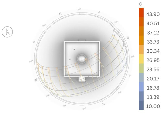
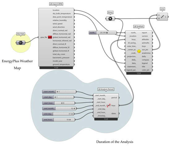
Figure 6.
Annual sun-path diagram.
3.2. Issues and Deficiencies
The evaluation of the current studio’s state was not limited to a preliminary analysis that will potentially aid in hypothesizing various challenges faced, but a detailed site analysis was performed to grasp the gravity of the situation and better understand the actual state from the student’s point of view. The focus was on issues concerning the followings:
- Daylight intake, which heavily impacted comfort levels.
- Different timings also demonstrate how dispersed and reflected radiation makes up most of the natural light entering the senior studio. Even if this kind of sunlight lessens the amount of embedded heat in the studio, the amount of natural light the studio receives will still be constrained. Consequently, one can deduce how the studio’s current design is incompatible with the surroundings and renders the entire strategy insufficiently viable. Hence, seniors frequently prefer to work on detail-oriented projects outside of the senior’s studio. One can infer that the current design consideration does not coincide with the requirements of the many expected tasks. Therefore, the student’s timetable and activities must be considered to develop the best possible solution and maximize the amount of natural daylight intake.
- Due to certain constraints, for example, the fact that the studio faces north, there will be limitations to the kind of adaptation the room may implement, which will further impact the level of efficiency optimization of the studio.
3.3. Simulations and Analyses
The studio is assessed utilizing a range of plugins and software in the subsequent extensive examination process. The assessment of the senior studio’s present state also resulted in the inclusion of new data in the research, which aided in the creation and development of the best solutions considering a set of criteria that were then produced, modeled, and evaluated. The analytical procedure was further divided into three primary steps as a result of its significance. To estimate how much daylight is caught, energy-related analyses first assessed the studio’s performance owing to solar radiation. Then, a wind study was produced by creating a wind rose diagram using fluid dynamics to simulate indoor airflow. Finally, a better grasp of the room’s ventilation helped examine the current level of comfortability in light of the percentages of sensations potentially experienced by the occupants. After preliminary data were collected annually, the three key analysis sections were often examined and reviewed throughout the course of two separate periods to obtain a more thorough assessment during the two times when students used the study space. This way of gathering data made it possible to generate a calculated understanding of the circumstances in the studio space.
3.4. Energy Analysis
Due to the fact that daylight and energy performance were the main issues raised and noticed at the senior’s studio and given the hot and humid climate of the UAE, energy-related analyses were conducted first. Because a better understanding of the climate and a more critical assessment of it will aid in identifying the critical factors that must be considered during the enhancement generation process in order to arrive at the best, and potentially an optimum, solution for the proposed improvements, the direct solar radiation, diffused solar radiation, global solar radiation, and daylight factor were all tested in this section. A correlation between the data obtained and the issues raised was identified [23].
First, the total annual direct solar radiation analysis was run, and the results obtained are shown in Figure 7. Direct solar radiation analysis only takes into account the direct sunlight vector from the sun to the study surface. Thus, Figure 7 further indicates how direct solar radiation is higher from approximately 8 a.m. to 4 p.m., except for midday, when it is at its highest, neglecting diffused radiation, which theoretically impacts the studio the strongest due to the studio’s orientation. Although the summer semester is known to be the hottest semester throughout the whole academic year, it is noticed that direct solar radiation is at its highest level roughly during the fall semester compared to the spring semester, which falls between the months of August and December, with the peak months ranging from the month of August until early October. Consequently, design enhancements should consider the amount of sun exposure during specific months and therefore balance out potential heat gain that might discomfort students and ultimately impact their learning curve. Moreover, as noticed in the fall semester, the amount of direct solar radiation is considerably higher than the data obtained in the spring semester. Thus, design considerations should accommodate and meet both semesters’ needs without compromising the studio’s performance.
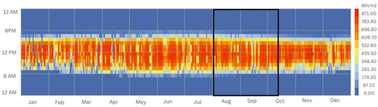
Figure 7.
Direct annual solar radiation.
Even if direct solar radiation is advantageous in determining beneficial techniques for performance optimization, evaluating it solely under these idealized conditions is insufficient. As previously mentioned, direct solar radiation analysis considers the geometry designated for study and determines whether the sun strikes the surface or not. However, this is unrealistic because there will typically be additional meteorological and environmental elements to consider. Therefore, it is crucial to consider the climatic circumstances even though direct solar radiation enables us to comprehend the pure exposure to the sun that the façade is susceptible to.
Therefore, the diffused solar radiation, shown in Figure 8, that the site receives throughout the entire year was the second step taken to analyze the site better. However, both types of assessments should be combined to produce a global solar radiation analysis, as illustrated in Figure 9, to better understand how the building functions and reacts to current natural situations. The entire quantity of direct and diffused sunlight that is exposed to a particular surface or geometry is known as global solar radiation. Therefore, if Figure 9 is carefully examined, it can be observed that the results were improved and changed, resulting in a more accurate output. Moreover, Figure 9 shows that during the months of June and July, primarily at noon, when the summer semester is typically in session, the maximum global solar radiation is at its highest. By comparing the quantity of global radiation experienced over the months of the two semesters, it is evident that the spring semester experiences higher levels of global solar radiation than the fall semester, particularly in the months of April and May. Despite the fact that the direct solar radiation in the fall semester is higher, the global solar radiation in the spring semester is higher because of obstructions such as clouds that are present in the fall semester, which is primarily cloudy. This shift, gradual change, and concentration of heat in particular months are typically normal because, in the fall semester, the weather changes from being very hot and humid to moderately cold and windy, whereas, in the spring semester, the weather changes from being cold, windy, and somewhat rainy to being hot and humid. Therefore, a few months are also particularly warm during the fall semester, such as September.
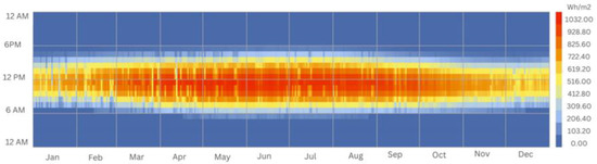
Figure 8.
Diffused annual solar radiation.
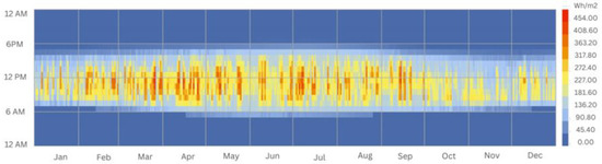
Figure 9.
Global annual solar radiation.
An assessment of the interior condition of the studio room was of utmost importance after evaluating how the environment is expected to interact with the building, particularly the building’s façade, to gather more information and construct a guideline that will aid in generating the optimal solution that would eventually suffice the needs of the studio and students. The analysis was completed by considering the façade of the university’s current design to check the daylight factor. Moreover, the daylight factor is typically given as a percentage, where it compares the amount of unobstructed daylight available outside in cloudy sky circumstances to the amount available inside a room. To further assess the studio’s skin’s impact on the area and the amount of indoor natural lighting system against future proposals, other strategies, such as examining the artificial lighting in use or upgrading the finishing material selection, will be excluded.
Dialux, which is a worldwide standard in lighting design software that mainly plans, calculates, and visualizes lighting for indoor and outdoor areas, was utilized to further analyze the throw of light and better visualize the data obtained. As indicated in Figure 10, there are three visualizers in which the room is shown as per the current design, and the amount of indoor natural daylight is projected into the studio [29]. In order to increase the analysis’s precision, parameters including the location, date, and time were given. Moreover, Figure 10a illustrates the analysis performed at noon on 15 December 2022. December was chosen since it tends to be one of the cloudiest months; therefore, examining the studio under the worst possible circumstances will further aid in supplying answers for similar situations. No light fixtures were identified because the purpose of this investigation was to further examine how much natural sunlight was entering the studio. Given that the lowest and maximum daylight factors should be 0.106% and 6.709%, respectively, the obtained daylight factor after the scene was configured and the analysis completed was 1.306%.
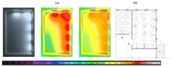
Figure 10.
(a) Daylight analysis of current studio stateroom shaded visualization (left), false-colors presentation (middle), workplace lux values (right); (b) seniors’ studio with current furniture arrangement.
Thus, this investigation demonstrates that students receive insufficient natural sunlight for the requirements and needs carried out in certain studio areas. In addition, Figure 10a further highlights zones and areas within the studio with specifications on how extremely rich or lacking daylighting and natural sources of lighting they are through false colors, making it easier to pinpoint areas that need to be tackled and set a profile for enhancement requirements. Logically, areas near windows and sun inlets have significantly higher levels of lighting, reaching a value of 1000 lx, with an expectation of certain areas reaching up to 2000 lx, whereas areas that are situated extremely far away from the windows are calculated to be equivalent to around less than 100 lx, which is drastically low.
Moreover, most of the space is well-lit in a manner that may suggest that comfortability due to heat gain is an issue, mainly near the windows. Consequently, this un-uniform scheme of daylight distribution within the studio and the insufficient amount of natural daylight to accommodate certain tasks and needs impacted the level of optimization and comfortability. To better grasp the gravity of the situation, Figure 10b shows the current senior studio seating arrangement, which, if linked to the obtained results, further highlights and confirms deficiencies in natural lighting and comfortability.
3.5. Wind Analysis
In this section, the Butterfly plugin from the Ladybug tools was used to carry out a computational fluid dynamics (CFD) analysis in which ventilation and indoor airflow were further examined. As a plugin, Butterfly is designed to quickly convert geometry to OpenFOAM and execute several known airflow simulations that are helpful for building design. At this phase, CFD analysis is conducted since wind movement and level of ventilation in a certain space ultimately impact the comfort levels of the user, which in this case, is something that the article aims to enhance eventually.
Thus, understanding how the room is ventilated in its current state will eventually aid in forming a better understanding of how deficiencies can be eliminated or limited through the utilization of wind through future enhancements proposed. Initially, the studio’s model was further simplified, as shown in Figure 11, before the execution of the analysis. The studio’s boundaries, several windows, and the door were typically the sole elements of the refined model, which served as the basis for specifying the room’s inlets and outlets later. As a result, the door was designated as the main air outflow, while the six windows were regarded as the primary air inlets. However, the wind velocity parameter was required for the CFD analysis code to function; therefore, both the spring semester, which runs from January until May, and the fall semester, which runs from September through December, were examined on a monthly basis to determine extreme wind values.
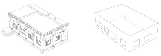
Figure 11.
The simplification process of the studio model for the CFD analysis.
For each month in the spring and fall semesters, a wind rose diagram was obtained to identify the extreme circumstances where the wind is at its maximum and minimum speed, shown in Figure 12. Moreover, choosing the extreme situations is equivalent to researching the worst-case scenario; as a result, if the proposed model is subsequently built in accordance with the extreme cases, it is well-equipped to meet the room’s needs without sacrificing performance during normal days. At first impression, it is clearly visible that the fall semester is generally windier than the spring semester, even though the spring semester has the highest wind speed. Moreover, the fall semester’s highest severe wind speed is 10.30 m/s, as shown, and it is noticeable all the way through December. Additionally, during the months of April and May in the spring semester, winds with a top speed of 15.40 m/s are noticeable. The value of the wind velocity is determined in light of these extreme circumstances which enabled the CFD code to run. Additionally, by carefully examining each month throughout the course of the two terms, this methodology provided a greater understanding of the current circumstances and how, with some improvements, it might meet the needs of the seniors during the two semesters better.
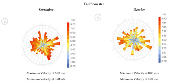
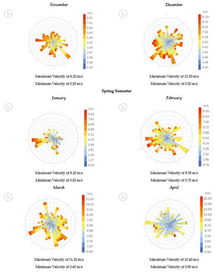
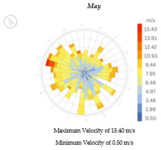
Figure 12.
Wind-rose diagrams of each month during the spring and fall semesters, respectively.
The maximum wind speed during the fall semester was found to be 10.30 m/s. However, it was 15.40 m/s in the spring semester after evaluating each month in each semester to better understand the diverse wind conditions and assess the design based on the extreme scenario. Primarily, the geometries that made up the room were further specified into air inlets (i.e., windows), air outlets (i.e., doors), and the actual boundary of the studio (i.e., walls, ceiling, and floor), as shown through the code in Figure 13. Furthermore, using the maximum wind velocity specified as the analysis’s vector, the CFD analysis in Figure 14 below depicts the wind flow pattern inside the senior room during the fall and spring semesters, respectively [30].
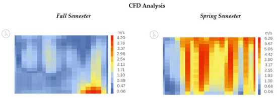
Figure 13.
The wind movement in the studio may be seen in a CFD comparison of the fall and spring semesters.
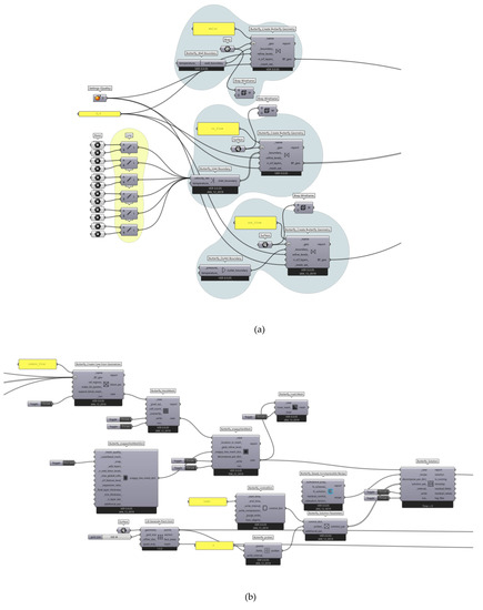
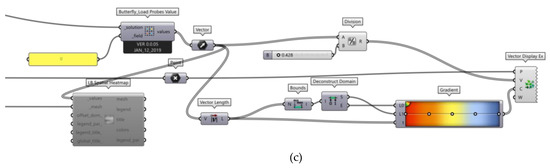
Figure 14.
CFD code CFD code; (a) partial CFD code of identifying the geometry for the analysis; (b) partial CFD code of the analysis; (c) partial CFD code of the visualization.
As shown in Figure 13, the CFD analysis indicates that during the fall semester, the wind moves at a considerably slower speed compared to the spring semester, which aligns with the climate usually perceived during the two semesters. During the fall semester, the average wind speed can be approximated at 0.68 m/s except for the area nearby the wind outlet (i.e., door), which has the highest speed of approximately 3.58 m/s. In contrast, during the spring semester, the wind was noticeably faster from the north-eastern direction. As the wind rose indicates, the wind is mostly prevailing from that direction, which, in turn, influenced the whole comfort level and efficiency of the studio.
As demonstrated by the results obtained, the average wind speed throughout the senior’s studio is approximately 4.42 m/s, except for smaller areas with an average lower speed of approximately 1.00 m/s. Furthermore, a greater understanding of how the wind moves through the studio shows how the ventilation is affected by the studio’s current condition, which has an additional impact on comfort and adaptability. Even if the design is not optimal, it is well known that excellent wind circulation can further increase the comfort level in a given space. As a result, examining the wind circulation helped provide a baseline for what students experience and what improvements might be considered later to increase users’ comfort levels.
3.6. Comfortability and Adaptability
At this phase, there are circumstances where the amount of natural sunlight exposure and the current arrangement of the furnishings may, in reality, affect how comfortable the seniors are working in the studio. In order to determine how and to what extent the current design’s lack of sunlight optimization along with the current ventilation state is affecting the students’ well-being and possibly their performance, given other factors, an analysis of the cooling and heating sensation inside the studio room along with thermal comfort analysis given the current parameters and context was conducted through the use of Honeybee plugin. Due to the initial focus on collecting data correlating only to the seniors’ studio and nothing else, (M8) was further simplified into blocks that make up the platform, the actual studio, and surrounding rooms for the analysis to be conducted, making the seniors’ studio the main target of the analysis, and neglecting all other rooms and studios during the analysis.
A comfortability and sensation analysis were conducted initially for the studio’s overall current state, as shown in Figure 15. Regarding the cooling sensations mentioned, the studio often permits one with a percentage of about 40.8%. Given the typical climate of the emirate of Sharjah or the UAE in general, it is assumed that the current state of the studio permits a somewhat mild sensation. On the other hand, the heating sensation percentage, with the modest exception of small patches, clearly shows how the current state, in fact, also restricts the discomfort level of feeling hot. The approximate heat sensation percentage is around 4.5%. Despite the fact that the current design is not deemed optimal on several accounts, it is important to note that students’ comfortability and experiences fall well within an acceptable range, necessitating further consideration when a new design is suggested for improvement.
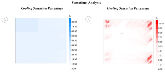
Figure 15.
Cooling and heating sensation percentages for the current studio state.
Based on the studio’s existing design characteristics, a second analysis was performed to calculate the percentage of thermal comfort, given the current climate. As noticed, few places near the north-western windows dissipate the most discomfort, with an average percentage of 29.54%, which is represented by red color, compared to the studio, which averages around 23.56%, shown in Figure 16. Although the current solution, to some extent, limits thermal gain and aids in comfortability, the studio room can still be improved to give students a better experience and help them achieve more according to the seating arrangement, tasks needed, and previously acquired data about ventilation and indoor sunlight intake. Likewise, it is crucial to keep students’ comfort levels within the suitable range or reduce their susceptibility to specific triggers that could affect their level of comfort.
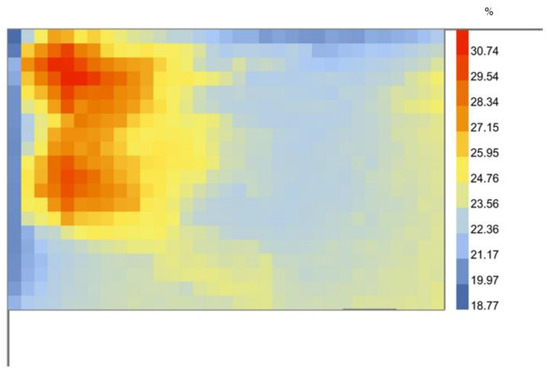
Figure 16.
Thermal comfort percentage for the current studio state.
4. Methodology
The research tries to offer the greatest possible user experience and comfort through an optimized solution while considering a set of criteria following a thorough analysis of themes linked to computational design integration with VR technologies, where the study area’s performance, elegance, and use came first. Grasshopper, a built-in plug-in for Rhinoceros 7, was used to obtain more specific and thorough data after the initial analysis. Other plug-ins, such as the Ladybug tool, which combines the Dragonfly, Butterfly, Honeybee, and Ladybug, were also used. In this study, the Ladybug plug-in was primarily used to perform energy-related analyses, such as sun-path, sun radiation, and adaptive comfort analysis. Moreover, the Butterfly plug-in was used to generate the CFD analysis for the studio and better understand wind movement and ventilation within the space, and the Honeybee plug-in was used to understand thermal comfort and generate data related to thermal comfort levels and heating and cooling sensations within a space. Furthermore, the structural soundness of the computationally created Islamic elevation variations was examined using the Karamba plug-in. Lastly, Dialux was used to obtain the daylight factor and further verify the effectiveness of the design in incorporating the environment with the design. The analysis was mainly performed to test, compare, and modify the enhancements compared to the current state to achieve the optimal solution.
On the other hand, generative design methods were used to create multiple variations that were inspired by the Islamic architecture seen on the facades of the buildings, particularly the Islamic pattern architectural elements that were generated using Parakeet, a useful algorithmic pattern generation plug-in and were then filtered using a predetermined set of selection criteria. Among the key selection criteria were overall beauty and elegance, structural soundness, performance enhancement, user comfort, and design efficiency. Moreover, two variations of each chosen pattern were observed per the various data collected for each semester to further explore how the design might be maximized through the elevation design and method itself. Lastly, it is necessary to apply and incorporate extended realities to confirm the findings, improve the outcome representation, and analyze it for future iterations and revisions until the goals are met. The results were then verified by connecting results from traditional and generative tools to a virtual environment where the improvements could be seen, tested, and experienced from the perspective of the user. Figure 17 illustrates the process used during the generation of improvements proposed and the validation phase.

Figure 17.
An overview of the research methodologies stages.
The entire process is also reliant on the outcomes, creating a never-ending loop of generations, iterations, experimentation, and verification. The main method for conducting the research is clearly shown in Figure 18. In order to set precise guidelines for the design and have a better understanding of how to approach the additions and enhancements that can be further applied, a thorough investigation was first carried out. Then, proposals were generated and tested after the implementation of the 3D model, which will further aid in creating visualizations (i.e., renders or VR environments) to better visualize, comprehend, and verify the outcomes of the proposals. If the generated outcome did not align with the objectives and did not aid in further performance optimization or enhance the users’ comfort, then adjustments to the design were made to better enhance the outcome while maintaining the selected selection requirements. The testing phase is repeated until the results are satisfactory and all objectives have been met. It is important to note that the analyses of the chosen variations in the proposed computationally generated Islamic pattern elevations are carried out with regard to all chosen variations, regardless of whether they succeed or fail in a particular phase in terms of the studio’s current condition. However, at the end of each phase, all findings were compared in order to choose the best variation out of all the ones that were chosen. By using this strategy, trials with a larger scope are possible in which each pattern can be changed and improved to satisfy the criteria.
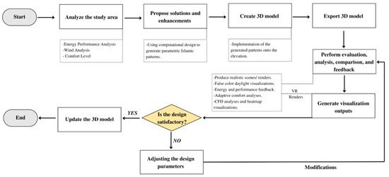
Figure 18.
The general workflow of research methodologies 1, 2, and 3.
4.1. Enhancements and Proposals: Preparing Parametric Design Model and Parametric Logic
The following section offers solutions and improvements to optimize performance while still preserving the elegance and beauty of the university’s design after carefully analyzing how the current design interacts with the surrounding. First, a closer examination of the existing themes and ornamental components used on the university’s façade was conducted to develop and propose a more cogent and consistent design. Then, the creative process was started, during which many concepts were analyzed and filtered to address two primary issues: increasing the amount of daylight input inside the studio and improving the users’ comfort levels. Finally, for a better understanding, all those implementations are shown and contrasted with the studio’s status as it stands now.
4.2. Patterns and Islamic Motifs at the University
The emirate of Sharjah is well recognized for displaying and valuing its history and legacy by incorporating the Islamic pattern into its architecture, as was already noted. The University of Sharjah’s extensive use of Islamic decorative patterns and themes is therefore not surprising. Moreover, the university’s exterior shows this unified façade that captures the beauty of Islamic architecture by merging numerous Islamic architectural styles inspired by various historical periods, as seen in Figure 19. Islamic patterns, ornamental motifs, geometric carvings, Mashrabiya, Qalawun set of windows, and different types of arches are all visible on the exterior façade of the university’s buildings. However, Islamic pattern is the primary decorative technique utilized to harmonize the existing window design with the university’s architectural style among the many decorative techniques. In order to preserve the uniformity of the overall appearance of the university’s façade, Islamic patterns are incorporated through the generative design technique in this paper. Moreover, the Islamic star can be observed as one of the key components of the Islamic design shown on the façades and highlighted through the current Islamic pattern. Therefore, including the Islamic star in the design process was essential for keeping the design’s language consistent.
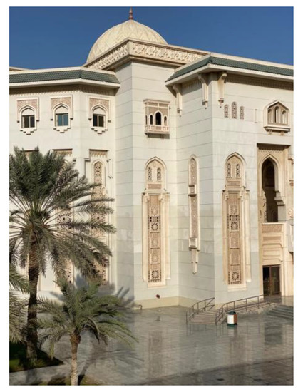
Figure 19.
M11 exterior.
4.3. Proposal’s Conceptualization Phase: Influence Factors
In order to secure the potentially effective and optimized design performance while maintaining the coherence and overall aesthetic of the building’s exterior, a conceptualization phase was scheduled to start after thoroughly understanding the room’s current state and identifying factors that needed to be modified and improved. The proposed implementations were only projected onto one of the elevations for assessment purposes and model sampling to better compare and appraise. Furthermore, after assessing numerous approaches and pathways, a group of variables that further influenced the design’s trajectory was identified. Enlarging window apertures was one method that was used to increase the amount of natural interior light intake, which is the ultimate and key goal at hand. Theoretically, increasing the glazed surface area of the studio approach should provide the area with the required amount of natural light, but it is also likely to have negative effects on other aspects, such as heat gain and comfortability. As a result, additional enhancements must be developed and considered to achieve balance.
Daylighting from windows or doors appears sufficient in a zone that reaches a maximum of 2.5 H from the opening, where H is the height of the aperture above the floor. When evaluating the studio’s current windows, the height from the floor reaches 2.70 m. Moreover, the depth to which the light can be projected is 4.05 m if the height of the window from the ground is multiplied by 2.5, as shown in Figure 20. As a result, it is possible to forecast how little light is provided inside the room using this basic study. One might further hypothesize that raising the windows’ height, measured from the ground up, will ensure that tasks will be completed much more easily and will further increase the amount of light intake. Hypothetically, if the proposal of increasing the height of the windows were considered, then a window with a height of approximately 4.1 m from the ground floor, which is later multiplied by the factor 2.5, would result in a coverage distance of 10.25 m, which is ideal given the width of the studio. Thus, this rough analysis further concludes that the proposal at hand can potentially increase the amount of natural daylight intake.
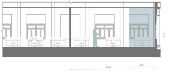
Figure 20.
Natural daylight intake visualization.
4.3.1. Indoor Light Intake
First, an analysis was performed to verify the amount of natural daylight intake at the studio. Therefore, the same procedure was followed again, and Dialux was used to visualize better and read the results obtained. Moreover, the same set of parameters was identified here to create a similar environment where the test can be conducted more accurately with as many controlled variables as possible. For this analysis, the concept of having wider window openings was tested to evaluate areas with a potential risk or propose enhancements. As shown in Figure 21, the Dialux analysis reflects the values obtained when such implementation is performed.
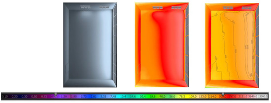
Figure 21.
Daylight analysis of proposed studio enhancement: shaded room visualization (left), false-colors presentation (middle), workplace lux values (right).
As observed, the indoor daylight factor has drastically changed to a value of 6.044%, which according to Dialux, surely provides enough sunlight that can accommodate the requirements of the room well without the need for further utilization of artificial lights, given that the lowest and maximum daylight factors should be 0.106% and 6.709%, respectively. Moreover, by investigating the data obtained from Dialux further, we can see that considering this option means that most of the room ranges between a maximum value of 4000 lx and a minimum value of 300 lx. In addition, the light distribution in this scenario is more uniform and equally distributed, ensuring that daylight reaches almost all spaces with a constant intensity. However, considering the proposed state of the studio, heat gain issues and various comfortability factors will be greatly impacted. Therefore, although maximizing the amount of sunlight is ultimately the goal, in this case, the room is to undergo modification to make the space ultimately comfortable and efficient.
4.3.2. Comfortability and Sensations
To further verify the comfortability factors that were influenced by the above proposal, the same set of analyses was conducted again to better compare the proposed approach against the original studio design. As stated, the current studio design offers students tolerable and somewhat comfortable sensations compared to the proposed design based on the data in Figure 22. The cooling sensation percentage is approximately 27.03%, whereas the heating sensation percentage is almost 24.33%, as seen in Figure 22. The drastic change in results, in which both the cooling and heating sensation percentages drew from the initially obtained results and shifted to much worse, is easily discernible. Therefore, while considering the proposed enhancements, certain considerations and precautions need to be considered to balance the heating and cooling sensation issues further. Furthermore, most of the approaches taken shed light on the proposal’s technicality rather than its practicality. Moreover, with this implementation initiated, a wide range of enhancements and modifications can be further facilitated without restrictions due to the unlimited adjustments offered. However, now that certain factors have been determined, the completion of the design profile is more ordered and controlled.
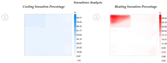
Figure 22.
Cooling and heating sensation percentages for the proposed enhancement.
To complete the design profile for the modifications that needed to take place, a thermal comfort analysis was performed to determine the percentage of comfortability in the studio after the proposed approach was roughly applied. Like the previously obtained results, a drastic change in comfortability was noticed when the proposed solution was tested, which increased the discomfort level. Such results were expected since the glazing ratio of the elevation has increased with respect to the solid. Moreover, as shown in Figure 23, the average comfort level of the studio is approximately 46.5%. Furthermore, larger patches of heated areas are dominant near window openings, with an approximate percentage of 54.5%. Therefore, as seen, the results obtained mainly highlight the drawbacks and potential risks of the rough application of the proposed enhancement. Such techniques and analyses were performed to foreshadow issues and risks that are extremely important to achieve an optimal design efficiently; in this instance, anticipating risk factors and highlighting undesirable effects aid in formulating and choosing the best strategy to handle the current design effectively.
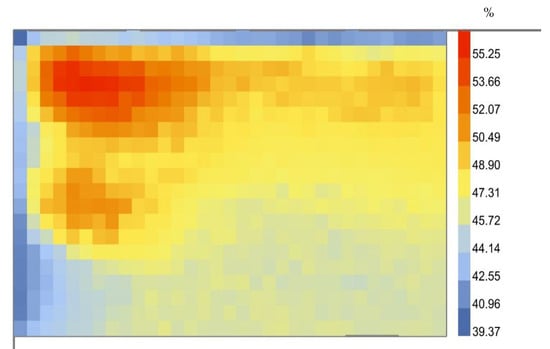
Figure 23.
Thermal comfort percentage for the proposed enhancement.
4.4. Pattern Generation and Variations
After carefully examining the studio’s current condition and carefully examining the decorative components and motifs used on the university’s exterior, the generative design process started with some essential factors in mind. The primary intention of the generative designs and the numerous iterations that followed was to create a screen that would ultimately aid in reducing the amount of sunlight entering the studio, potentially lowering the amount of heat gain, and enhancing airflow, thus raising user comfort. Initially, the wall that will be further created was determined to be mostly constructed through Islamic patterns, specifically the Islamic star, by using the excessive designs seen on the university’s building facades as inspiration. Moreover, incorporating the Islamic pattern into the wall design will aid in attaining the research’s goals while upholding the architectural vocabulary of the university, not only beautifying the area in front of the main building. Numerous geometrical designs were created using the Parakeet plugin, which focuses on algorithmic pattern generation. By using different grids or tiling and pattern-creation components, more than fifty generations were produced, and more may be generated if necessary. Based on initial selection criteria, which include whether the pattern would satisfy the needs of the room, if the generated pattern is aesthetically pleasing, whether the obtained pattern would disrupt the coherency of the patterns depicted on the buildings’ exteriors, and whether the proposed pattern will limit visibility, twenty generated patterns were chosen. Although the Islamic pattern was crucial for attaining this coherence and visually beautiful façade at the beginning of the generative process, a few initial attempts and changes were carried out without the usage of an Islamic star. For a variety of reasons, the outcomes of such trials were unsuccessful due to how patterns were either encouraging vegetal geometries or were so dense as to finally impair vision and, more crucially, studio performance.
Furthermore, the utilization of the Islamic star in the generative process was included after numerous tests. The twenty chosen designs were thought to be the most likely to satisfy the needs and requirements of the room, as well as the closest batch with the desired features. Generally, the generation of the Islamic pattern and, more specifically, the generation of the Islamic star is intricate and detailed; however, because Parakeet components were already present, it was quite simple to build several versions to test. Figure 24 depicts the code used to generate one of the patterns; however, the same script was used throughout the entire process except for the base tile used and the type of pattern being constantly alternated. It is also important to note that all the patterns shown below in Figure 25 were created by combining two pattern-creation components. It was discovered that using this merging process led to more interesting and intricate geometries without exhibiting excessive repetition or harming the studio’s overall performance. A grid or tiling component with the required dimensions was initially created to generate the pattern. Then, the generative pattern elements were chosen and adjusted as necessary. Afterward, the created curves are offset to the desired thickness when the pattern is hooked up and molded using the chosen grid or tile.
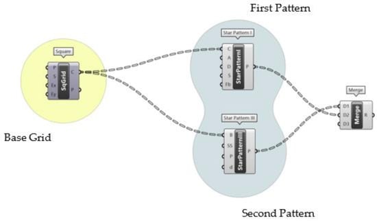
Figure 24.
Pattern generation partial script.
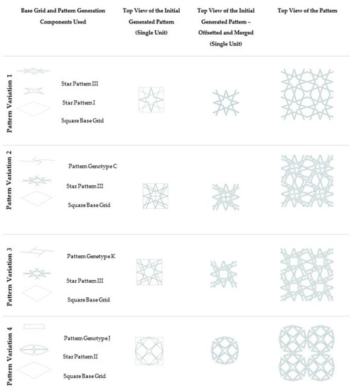
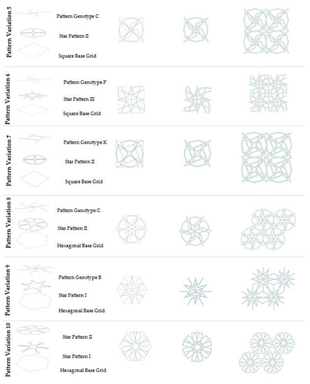
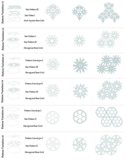
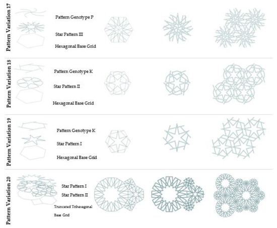
Figure 25.
The twenty selected generated patterns.
4.5. Analysis and Selection
As mentioned, the twenty chosen patterns are some of the most intriguing variations produced through the generative design process. Furthermore, the apparent basic geometrical combinations reflect the patterns’ complexity, adaptability, versatility, and intricate detail. However, to further minimize the twenty pattern variations at hand, more specific and clear selection criteria should be used.
First, as this will certainly have an impact on all other options, an elimination based on the aesthetics of the pattern formed was conducted. Thus, the level of detail, patterns of varying complexity, type of generative pattern employed, and expected performance were all considered. The visualization of how the pattern will ultimately appear after identifying the solid and void components allowed for simultaneous consideration of the structural integrity and performance of the elevation. Later, the effectiveness of the patterns considered and whether they will enhance user performance generally will be determined by all three selection criteria, which are aesthetics, performance, and structural integrity, as opposed to whether it will merely add aesthetic value to the façade without being functional. Furthermore, the four patterns represented in Table 1 were the ones that met the already described preliminary analysis and criteria.

Table 1.
Selected four generated patterns.
Additionally, the created designs were intended to resemble, but not be a replica of, the patterns found on the university’s façade. In order to find a connection between the patterns created for the suggested design and what is now displayed on the university’s exterior, Figure 26 was used as a reference. Furthermore, the intention was to develop something closer to the existing design than a clone due to how versatility and performance were taken into account. Moreover, unlike the proposed use, which is primarily performance-based, the Islamic motifs currently seen on the university’s façade are normally utilized as a decorative element.
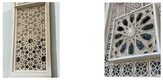
Figure 26.
Inspiration photos for the proposed generated designs.
Regarding the four selected patterns, one thing they all have in common is that they were all created using a single Islamic pattern component. The fact that several characteristics, such as the grid and the size of the grid cells, were not limited or specified further contributed to the variety of the outcomes. Additionally, the complexity and level of detail varied according to the grid and generative pattern components used. Furthermore, different ways to create the patterns were tested to see which technique would best meet the students’ demands while considering the methodology that would be used to improve the studio’s performance [31].
Early investigations also confirmed that if the following patterns were to be continuously used, there would not be any problems. For instance, pattern variation 1’s straightforward geometry improves the potential for further experimenting with the pattern to suit the requirements of the studio space. On the other hand, pattern variations 10 and 14 essentially use the same technique because they were created using a hexagonal base grid. However, the generative patterns are highly variable, which calls for adaptability and structural robustness. Finally, pattern variation 11 is thought to be the most complex design among those chosen, allowing for yet another greater range of trials and tests. However, a full evaluation of the situation in the room following the enhancement and implementation of the four suggested choices was performed in the following section [32].
As indicated, the three pillars chosen as the selection criteria were further examined in the parts that follow. Functionality, structural integrity, elegance, and coherence are a few of the analyses cited. Due to the diverse functionality around the area and the numerous tasks anticipated based on the location, it is important to keep in mind that the proposed generated designs will not be implemented and tested on the full exterior of the studio room, as mentioned previously. As a result, the elevation depicted in Figure 27 will continue to be developed during the analysis phase, and only the proposed generated design will be executed for it. The proposed design can also serve as a template, allowing the same process and approach to be used elsewhere should the need for the current improvements arise—just with other parameters.
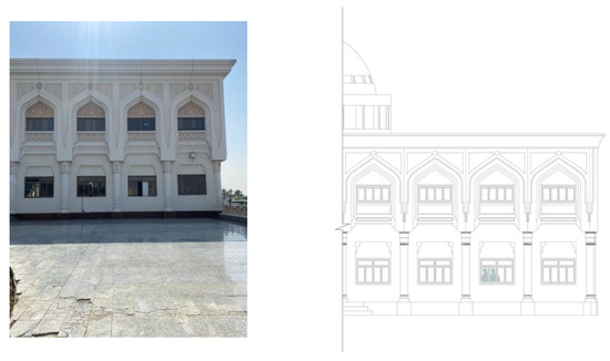
Figure 27.
North-east elevation: current real state (left); technical visualizer (right).
4.5.1. Structural Integrity
The proposals’ structural integrity and capacity to maintain their form rank are among the most crucial elements to consider. Although the applied load should not pose any issues because the majority of load transfer occurs through other structural elements and the proposed elevation does not act or influence the flow of force, it is still important to check the dead load of the generated proposed wall to ensure structural integrity and prevent dangerous situations [33]. Therefore, the first step was to determine whether the generated pattern was formed in a way that could be further modified to provide optimal adaptation of structural integrity or whether the generated pattern was not connected well, in which case any modifications could ruin the complexity and overall look and performance of the screen. As a result, the initial phase of the created pattern was further examined and evaluated while considering numerous factors. Moreover, by using Karamba, which is an interactive parametric engineering tool used in early design phases to perform quick Finite Element Analysis (FEA), as seen in Figure 28, Figure 29, Figure 30 and Figure 31, each pattern was tested twice with a different support location in mind for a better understanding of the deformation level of the screen under the dead load imposed on the elevation by gravity. As shown in the results obtained, most patterns will have a certain level of deformation when the support location changes; this, of course, does not apply to pattern variation 1, which shows resilience regardless. However, as previously mentioned, in this case, the elevations proposed are not required to resist or carry any load. Since the following proposals are regarded as templates, a structural analysis that considers and evaluates other cases where the screen in question can be used as a structural element ought to be considered. Furthermore, in this case, all the designs created at first could retain structural integrity because they were not expected to carry loads, but adjustments had to be made to boost effectiveness and overall strength for safety reasons as well as performance. Playing with the screen’s porosity was one of the many suggested improvements for how efficiency and performance might both be optimized [34].
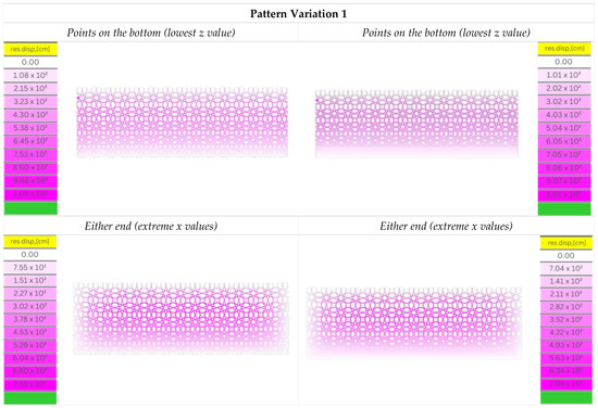
Figure 28.
Structural analysis on pattern variation 1.
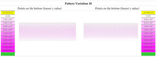
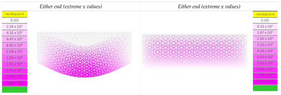
Figure 29.
Structural analysis on pattern variation 10.

Figure 30.
Structural analysis on pattern variation 11.
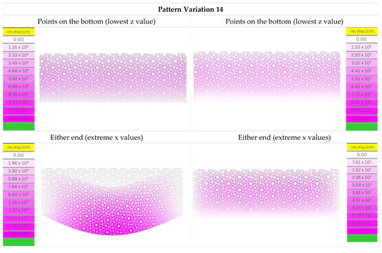
Figure 31.
Structural analysis on pattern variation 14.
A vertical gradient was discovered to be the most appropriate when the design’s structural component was considered. More specifically, the vertical gradient strategy was intended to increase the size and, consequently, the intensity of the porosity in the top section. On the other hand, the lower portion of the created suggested wall was designed to lessen the size of the porosity. Consequently, the methodology used not only used more material in the lower area of the wall and less material in the upper section, helping to secure the required structural integrity, but it also improved and increased the efficiency of the studio.
4.5.2. Elegance and Coherency
It is necessary to consider the proposed designs’ elegance and coherence while developing the selection criteria. Theoretically, every design can be further modified in terms of structure or functionality; however, creating an exquisite overall look necessitates the use of well-chosen elements. Even though the standards for elegance in Islamic patterns frequently change depending on the context, culture, and historical and religious references, a few standards, such as symmetry, proportion, complexity, repetition, contrast, movement, and unity, are still regarded as the cornerstones of the selection criteria used to create new patterns. Since it helps to produce a sense of balance and harmony in the design, symmetry is typically regarded as a vital component of Islamic geometrical designs. Moreover, well-proportioned parts that accentuate the pattern’s intricacy are necessary for a geometrical design to be coherent. Due to all the intricate features and ornamental motifs that can be merged and highlighted through the Islamic geometrical design, complexity is another crucial issue that is considered. Although parts in a geometric Islamic pattern will typically be repeated inside a certain visual flow produced by the high degree of repetition of forms and lines, repetition and movement are typically two characteristics that complement one another. Moreover, contrast is a component that highlights pattern variation differences, such as the contrast between light and dark parts or between various hues overall.
In the current situation, it was still more challenging to attain elegance and overall design coherence due to the pre-existing limits and design of the university. At first, maintaining an elegant design was constantly referred to and considered when designing the approach required to address the issues and enhance the students’ experiences at the studio. Therefore, the idea of adopting the Islamic design as the glazing’s frame was given greater thought. The glazing behind is protected by design, generally handled as a constant pattern. This minimizes heat gain and sunlight exposure while adding a beautiful touch to the façade. However, this idea was swiftly dropped because it could further enhance the developed design while maintaining coherence with the outside of the complete structure by considering the building’s structural and performance qualities. In order to support that notion, the design was altered to follow a vertical gradient, where the pattern voids grow larger as you travel higher. This approach was chosen not only because it maintains the building’s appearance while bringing a subtle vibrancy and dynamic touch but also because it allows the most indirect sunlight absorption, which can further enhance the learning environment for students inside the studio. All the previously shown patterns underwent the same fundamental alteration procedure. First, a uniform pattern spanning the entire wall was formed. Next, a straight line was drawn and recognized as a curve using the attractor curve principle, further scaling the uniform surfaces into the shapes shown in Figure 32.
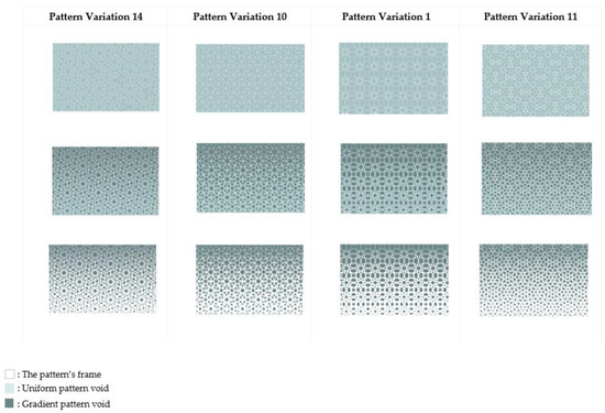
Figure 32.
Gradient implementations on the generated pattern screens of the studio’s elevations.
The four pattern variations are arranged in Figure 32 in a way that illustrates how the initial idea evolves into the final design. An inverse methodology was used when changing the screen, enabling monitoring of the void rather than the real structure. The uniform pattern is displayed in the first row, while the dark areas are the patterns’ voids. This method also allowed a chance to see the pattern through its voids rather than its true structure, which helped to better grasp how it behaved and changed. The code was applied to the uniform surfaces in row one. Moreover, in the second row, which also demonstrates the geometry and ratio differences, the intensity and strength of the charge used to create the gradient effect were experimented with until an optimal design was reached while maintaining the patterns’ coherency and visual appeal through the transition. The last pattern is displayed in the third row, where the shaded area once more denotes the screen voids. When comparing the outcomes of the suggested created patterns, it is possible to see the intensity variation, which helps determine which level is most appropriate and, in turn, improves the students’ studio experience.
Four elevations of the implemented generated patterns are shown in Figure 33. Moreover, these four elevations help better comprehend the wall’s general beauty and coherence, as well as how, despite incorporating a novel idea into the university’s pre-existing architecture, the coherence and harmony were maintained. As noted through the illustrations in Figure 33, the intended façade guards a glass wall. However, the glazed wall starts at 0.90 m from the studio’s ground level due to architectural limitations and safety measures. As a result, unlike the upper portion, the lower portion of the pattern typically looks like it was carved into the wall.
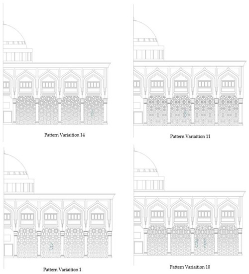
Figure 33.
Implementation of the generated pattern screens on the studio’s elevation.
4.5.3. Functionality
The proposed generated patterns’ functionality was then examined to ensure that it improves the experience inside the studio. This was performed after securing the structure’s structural integrity and confirming that the methodology used enhances the building’s overall visual appearance while still being consistent with the rest of the pre-existing design. However, a preliminary analysis was performed by looking more closely at how the gradient affects the pattern and forecasting the behavior and conclusions of each one before running the studies again on the newly generated patterns. As can be seen in Figure 34, the four proposed patterns are displayed using a color scheme where the darker the shade, the greater the porosity. Furthermore, the pattern itself, as well as how complex it is compared to other created patterns, significantly impacts porosity variation and level of intensity. For instance, given that the porosity range is not vast, pattern variation 11 is the most detailed variation among the four suggested; therefore, it can be anticipated that the light intake will not be particularly high.
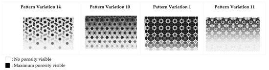
Figure 34.
Porosity analysis of the generated pattern screens on the studio’s elevation.
In order to critically evaluate the energy performance and more accurately ascertain the efficacy of the suggested designs, the tests that were carried out on the current condition of the room were redone with the newly designed and proposed generations. With the exception of applying it to the newly generated versions of the wall, the light analysis intake was first completed using the same parameters as before. Again, the result was as expected, given the first analysis of the pattern density. Each pattern, as can be seen in Table 2, Table 3, Table 4 and Table 5, was scaled, tested, and reviewed to see whether the necessary daylight factor could be obtained while still preserving the geometric gradient and if the design language was threatened or lost by the transition made. Each pattern underwent three separate analyses during the analysis phase in line with the façade’s proportion of glazed to solid areas. The least porosity range fluctuation is seen in pattern variation 11, the most intricate pattern created, as shown in Table 5. It is obvious that the light performance is poor and that the daylight factor is lower than intended. Because the amount of daylight factor was less than the percentage achieved by the current design, the pattern was rejected. Even after changing and modifying the porous pattern size, the geometrical transition would either impair the overall attractiveness of the pattern represented on the elevation or the daylight factor would still be insufficient, as in the situations depicted in Table 2, Table 3, and Table 5. One effective sample, sample number 2, from pattern variation 1, which is noted in Table 4, shows results that are superior to those of the present senior studio design while maintaining the pattern’s fine intricacies and overall geometric design.
Table 2.
Indoor daylight intake analysis: pattern variation 14.
Table 3.
Indoor daylight intake analysis: pattern variation 10.
Table 4.
Indoor daylight intake analysis: pattern variation 1.
Table 5.
Indoor daylight intake analysis: pattern variation 11.
After evaluating the enhancement and effectiveness of the indoor light intake with the implementation of the recently presented designs, ventilation and wind flow were further explored and analyzed. As previously mentioned, the studio’s current condition causes a small amount of turbulence inside the room during the spring semester, which would not be helpful for the students, given the work they must complete and the weather outside. The developed and suggested designs make an effort to increase indoor airflow and unify it through the design of the screen in order to satisfy the demands and requirements of the senior students better. Table 6 demonstrates that all versions tested improve airflow movement throughout the studio, indicating that the newly suggested adjustment may help increase the students’ comfort levels. When compared to all other proposed patterns throughout the fall and spring semesters, pattern variation 1 offers the most wind, according to the results shown in Table 6. This is because the porous pattern is thought to be the largest. Nonetheless, compared to the most recent studio wind flow analysis, wind flow is still controlled and minimized. Compared to the other suggested pattern modifications, variation 11 offers the least wind ventilation during the fall semester and a more turbulent wind pattern during the spring semester. In general, the four modifications that sought to provide the user with improved degrees of comfort were consistent in the wind pattern displayed and values acquired.
Table 6.
CFD analysis on the four proposed generated patterns during fall and spring semesters, respectively.
4.5.4. Adaptability and Comfortability
Several variations were proposed, constructed, and tested after a thorough analysis of the senior’s studio to achieve acceptable levels of comfort while also supplying the required amount of indoor light intake. Pattern variation 1 outperforms all other patterns in terms of results because it preserves a higher proportion of daylight factor than the present studio condition while still utilizing wind movement in a way that lessens discomfort sensations. The Ladybug plugin was used to conduct an adaptive comfort test, which simulates the interior of a building where a heating or cooling system is not in use and occupants have the option to open windows for natural ventilation, in order to better understand the drastic change pattern variation 1 influences the studio with. The adaptive comfort analysis’s findings for the fall and spring semesters are shown in Table 7 below [35]. Furthermore, it is clear that generative pattern variation 1 boosted comfort levels. Other than a few isolated hot cases, the studio’s general state is generally neutral to cool. For example, as shown in Table 7, the comfort level is insufficient during November, causing the studio’s condition to lean more toward a hot environment. However, comfort levels rose in the studio following the integration of generative pattern variation 1, and the environment of the space changed in line with that. As a result, the objectives of proposing an enhancement that can greatly outperform the current studio design and offer more optimal solutions are achieved.
Table 7.
Adaptive analysis: fall and spring semesters, respectively.
5. VR Implementation: Validation, Enhancements, and Applications
The procedure of linking the available results to the tools of virtual reality was carried out in the following part. In addition, VR technology was used to enhance visualization to comprehend, evaluate, and assess the design process and final product, in general, more fully. Integrating the use of VR technology, the selected skin variation and the studio room circumstances were assessed primarily based on the effectiveness of the indoor light intake, wind movement, and ventilation assessment. A virtual scenario that simulates a senior student’s typical interaction in the newly built environment was used to examine and evaluate the newly expanded senior studio. Utilizing such a potent tool during the designing and evaluating stage of the project not only ensures its security and helps anticipate potential risks or conflicts, but it also aids in understanding the perspective of the user and how the interaction will be carried out, which secures higher levels of practicality and comfortability. Therefore, even though the design examined in the following sections has already passed all performance and aesthetic-related tests and evaluations, deeming it to be the most optimal solution, this may not always be the case when the project is brought to life due to certain factors that cannot be analyzed through tests and experiments. Further evaluating whether the concept and goals in mind were reached throughout the actual design or were lost somewhere throughout the process is made possible by viewing the actual design and engaging with it through the VR machine.
Moreover, employing a VR device to analyze the project can ultimately assist in placing the current design in more realistic scenarios and circumstances. For instance, if a region experiences heavy rainfall, rain simulation can help architects visualize how their projects interact with the environment. Even better, with the help of virtual reality technology, architects can assess a building’s resilience to natural disasters such as storms, earthquakes, and floods.
5.1. Model Preparation
Due to how any inaccuracy would subsequently be transferred into the VR machine and affect the entire experience, the preparation step of the model is typically the most important phase. Pattern variations 11, 1, 14, and 10 were evaluated, as previously demonstrated, and the best-optimized pattern among them was found, considering the numerous generations from each pattern variation. In this phase, various tests and visualization tools are used to further examine the selected optimized solution, which is pattern variation 1. These tools help in both interpreting the data obtained in a much clearer manner as well as help in analyzing how components and people will be able to interact with the design generated. The implementation of generative pattern variation 1 on the senior studio’s longest wall is demonstrated in the following example. The two primary interfaces utilized to generate all the patterns seen throughout this paper are Rhinoceros 7 and its built-in plug-in grasshopper, as was previously noted. Hence, following the acquisition of the Revit file for the AED building, the file was later turned into a Rhinoceros 7 file to ensure a simple workflow between the previously created patterns and the current studio model. Additionally, Twinmotion, the preferred rendering program, was chosen because of its seamless connection with Rhinoceros 7 for rendering. It was advantageous to perform numerous iterations of the testing process with Twinmotion since the plug-in synchronizes the most recent update of the model with the rendering interface in Twinmotion without any issues or extra need for file conversion. The procedure’s initial step involved connecting the VR headset and the currently used device. Two applications had to be loaded and connected for the headset to correctly pair with the device in use. Therefore, attaching the test environment to the VR headset required only clicking a button. Then, setting boundaries and floor level were two important steps required for the VR headset to operate accordingly.
The main objective now is to improve the model once the VR headset and the device in use have been connected. Thus, the first step was identifying the site’s location, which would establish the North direction. Finding the North direction can help with the first type of analysis, which examines how much indoor natural light is obtained and how the studio will appear at various times of the day. In general, changes were made primarily to streamline the visualization process later and remain as close as possible to replicate the existing environment. The overall experience can be unsettling at first because it may leave the user feeling a little bewildered. As a result, the user started to roam the space and become familiar with the commands and controls nearby. Although this phase was not required, ensuring a seamless process when the project’s actual bridging and streaming began was essential. The approach used is unquestionably very different from one that might have been thought of or implemented if the main goal had been to showcase the project to stakeholders or for educational purposes. The aim and goal of bridging existing technology and virtual reality were to purely validate, assess, and explore applications in the project.
5.2. Aesthetical Aspect
“Previewing the modified studio through the use of the VR headset felt surreal”, was the first statement after experiencing the studio with all the proposed enhancements included. In this section, the focus of the analysis is human experience, emotion, and well-being. The room provided a sense of familiarity while still provoking a subtle vitality and dynamicity, which aided in forming a stronger bond between the user or viewer and the space. Generally, the design further introduces subtle changes that will not totally shock and disorient students when introduced to it. On the contrary, there will always be a feeling of familiarity that is underlaid with the new techniques and proposals added for further enhancements. The overall connectivity and aesthetics of the proposed design were also other factors that were closely examined by using the VR headset. Upon first inspection, the distinct differences between the two walls (i.e., the old existing and newly proposed walls) are extremely bold. Through the utilization of the VR headset, one can see the two walls compared side by side with all the aesthetic differences they offer on display. One main point highlighted through the newly proposed wall was the subtle volatility and dynamicity of the design observed. Moreover, the pattern gradient that is demonstrated through the wall not only for functional reasons that are highlighted again later but also for aesthetical and conceptual reasons aided in converting the area’s atmosphere and helped in translating the buildings’ architectural style better not only for the passers but also for the occupants inside. Theoretically, the current design can facilitate visual connectivity between seniors working inside the studio and the surroundings, which further stimulates factors such as social sustainability.
5.3. Indoor Light Intake Performance
One evaluation criterion that was analyzed extensively throughout was the performance of the indoor light intake. Through the previous sections, a set of data illustrated how, through experimenting with various pattern variations while playing with the porosity area percentage, the ideal geometrical pattern variation was pattern variation number 1, sample number 2, with a daylight factor of 1.317%. Moreover, this pattern variation specifically offered more sunlight than the current studio design while maintaining the overall design’s pattern gradient and flow without losing the geometrical configuration in translation. Furthermore, the pattern in question was further examined, analyzed, and explored by utilizing the VR headset, which further clarified how the pattern is expected to maximize the amount of indoor light intake as well as understanding how shadows will be cast in the given space. The utmost important objective validated through the utilization of the VR headset was to ensure that the proposed design, in fact, supplements the area with more light intake while still providing the required level of comfort without causing unnecessary distractions such as shadows. In Table 8, three states of the seniors’ studio were further explored and closely examined. As seen, the three states reflect three different periods during a day in the month of May when the students will be using the senior studio. Furthermore, by interacting with the space during those chosen three times and other times during the day, a better understanding of the studio’s condition was formulated. Moreover, Table 8 clearly depicts how the proposed solution for the senior room provides the studio with sufficient lighting at different times of the day. Therefore, the proposed solution aids in increasing the amount of diffused sunlight that eventually contributes to the performance of indoor light intake. Thus, the solution proposed casts soft shadows during only the early hours of the day, which provides students with sufficient lighting during the rest of the day with no visual obstruction.
Table 8.
Senior studio through VR headset at three different timings during the month of May: 8 a.m. (left), noon (middle), 7 p.m. (right).
5.4. Wind Movement and Ventilation Assessment
Second, by using the VR headset, additional evaluation and assessment of wind movement and ventilation within the seniors’ studio were performed. By comparing the suggested solution to the current studio design condition, CFD studies previously demonstrated variations in the wind movement pattern. Furthermore, it was crucial to pick a strategy that, given the constraints of the suggested solution, may possibly mimic the sensation experienced in real life. Heatmap representation was chosen for better visualization in the particular situation, even though further technical assistance or the addition of sound effects may have produced a close portrayal of the environment. As was evident throughout the analysis phase, the heatmap employs a method in which different patches denote different wind speeds and vector arrows denote the vector value of the wind velocity where the wind intensity and direction are collected. The heatmap, for instance, shows the wind pattern inside the seniors’ studio in Table 9. It also helps to better comprehend how the wind will be distributed and what ventilation or wind circulation is anticipated, given the physical context of the region, by presenting such imagery and merging it with VR technology.
Table 9.
Senior studio through VR headset: wind analysis visualization.
5.5. General Design Evaluation and Future Enhancements
Ultimately, the new design implementations were more thoroughly included in the current studio design with the primary objective of improving overall performance efficiency, leading to a considerably more optimized design. Moreover, among the several goals that were considered when creating the suggested displays were factors such as user comfort and experience improvement. It was also discovered that the suggested pattern variation 1, in fact, improves the performance of the studio while still offering the users a high level of comfort through multiple analyses and the integration of the VR headset in order to further verify the data and results obtained in a virtual replica of the studio. It was noted that the studio offers homogeneous natural lighting with nearly no shadow to support visual tasks and visual connectedness. However, in all the analyses performed and conducted, elements such as shadow, furniture arrangements, illumination, and other factors were neglected. To further comprehend how the student desks will appear, react, and function with the new implementations performed to improve the studio’s performance, a scenario where shadows are cast, for instance, which is seen unfavorably, can be further explored.
6. Results and Discussion
The main goal of this research was to generate, enhance, and validate multiple geometrically generated variations that can potentially enable a much more sustainable, efficient, and optimized solution for a specific studio in the Architectural Engineering Department (AED) at the University of Sharjah. Initially, a set of environmental simulations and analyses were conducted to further understand the nature of the United Arab Emirates (UAE) and to generate a rough guideline for the studio’s performance. Moreover, the studio’s current state was extensively inspected during the fall semester and spring semesters, respectively, for the proposed solutions to better accommodate the conditions under which seniors usually occupy the studio. Furthermore, a thorough understanding of the architectural style conveyed was developed, as was a deeper comprehension of the intricate decorative Islamic elements and motifs found on campus, especially Islamic patterns and the Islamic star. Therefore, after evaluating the current state of the seniors’ studio and understanding the seniors’ needs through the different semesters based on their needs and typical activities, a set of geometrically oriented Islamic pattern elevations was proposed as a method of enhancement to the proposed approach. This section further highlights a summary of the major findings, as well as the major factors and contributions accomplished through the proposed solution throughout the article.
Showcasing the several generated Islamic pattern screens and the overall selection process was mainly performed through a set of carefully curated criteria that secured the consistency of the pattern and its contribution to the aesthetic aspect of the building and the overall harmony of the façade, the environmental performance and sustainable measures taken and achieved through the design to secure its functionality, and surely, the structural integrity of the design and its durability over time.
As a result, four different Islamic pattern screens were chosen: pattern variations 10, 11, 14, and 1, which were all tested, respectively. Initially, an assessment of the indoor light intake was carried out to investigate which of the proposed patterns offered the highest daylight factor. For each pattern variation, multiple generations were tested to determine the percentage of porosity that will eventually achieve the highest daylight factor in each batch; however, the analysis is automatically terminated if one of the previously mentioned criteria is no longer fulfilled. Pattern variation 14 was analyzed three times with values of 0.852%, 0.908%, and 0.969%, respectively, for the daylight factor, yet since pattern variation 14 did not fulfill the criteria, the analysis stopped, and the pattern variation did not pass. Then, pattern variation 10 was analyzed three times with values of 1.019%, 1.086%, and 1.279%; however, the pattern variation did not pass for similar reasons as pattern variation 14. Moreover, pattern variation one was also tested three times with values of 1.245%, 1.317%, and 1.467%, where sample generation 2 was chosen to be the most optimized solution in the batch while still fulfilling all requirements, unlike generation 3. Lastly, pattern variation 11 was analyzed three times with values of 0.834%, 0.940%, and 1.084%; all three generations failed the test. Below, Table 10 shows the summary of the results obtained from the daylight intake analysis.
Table 10.
Daylight factor results obtained through Dialux.
Consequently, ventilation and wind analyses were conducted, which also examined the four suggested Islamic layouts. Ultimately, the wind component was primarily considered to potentially achieve high comfortability by improving the flow of wind within a particular location. Moreover, computational pattern creation suggests skins that reduce the turbulence in wind movements observed during the current state of the studio design and unify the wind flow within the space, thus improving the comfort levels within a space. As a result, an adaptive comfort analysis was carried out to compare the senior studio with pattern variation 1 to the current condition of the studio. The results show that comfort levels were improved in each semester, respectively, ensuring optimal functionality and efficiency.
It was noted that the proposed implementation, in fact, raised the studio’s level of comfortability and thereby improved the experience for users. Finally, in order to validate, assess, and further explore the potential of the selected proposed pattern, a bridge between cutting-edge technologies, such as VR in this case, and already-used technology took place. By using the VR headset, the proposed Islamic pattern wall was further inspected and again evaluated based on the selection criteria initially followed. Moreover, indoor light intake and ventilation and wind movement were verified and visualized through the virtual environment, which added context to the design and highlighted the studio’s performance with the enhancements made. As a result, the design satisfied the requirements and met the design criteria determined earlier in the study.
The overall workflow for this article is shown in Figure 35, where it is shown that after the early phases of analysis, experimental generating processes were used, along with implementations of those processes and additional modifications made during the research. Moreover, Figure 35 shows a summary of the work process and the outcomes attained during the course of the research’s many phases. Lastly, despite the limitations observed in the application to the case study, integrating VR technology with computational tools has yielded significant benefits. These benefits include exploring the relationship between subjective choices and choices based on computational tools, evaluating the level of subjectivity involved in the validation process with VR, and identifying the participants who were involved in this phase. As such, the integration of VR with computational tools has resulted in several benefits, including:
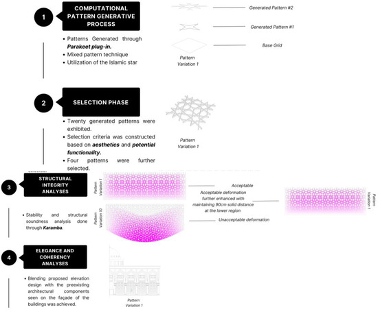
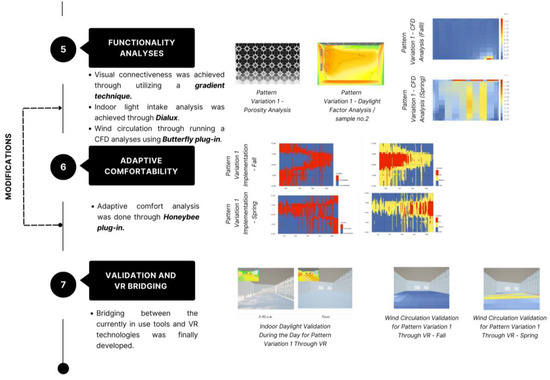
Figure 35.
General work scheme followed within the research methodologies 1, 2, and 3 implemented in the research study.
- Enhanced visualization capabilities, allowing users to interact with complex models and simulations in a more intuitive and immersive way.
- Increased accuracy and precision in data analysis, leading to better decision-making.
- Cost savings through the reduction in physical prototypes and travel expenses.
Figure 35 shows the general work scheme followed within the research methodologies stages 1, 2, and 3 implemented in the research study.
7. Recommendations and Future Studies
As part of expanding on the research at hand and obtaining further information, certain factors can be taken into consideration, such as the study of material used either for pattern fabrication or finishing material for the studio, which ultimately impact factors such as thermal properties and carbon emission.
Moreover, to possibly improve comfortability, the furniture orientation and layout design can also be modified and tested. Additionally, it is thought to be a sustainable strategy to consider that the fabrication of the actual wall can be accomplished by digitally printing the wall from recyclable materials, thereby increasing the green footprint. Lastly, in order to attain the best design, software and artificial intelligence techniques can also be integrated and implemented to secure efficiency during the design process.
8. Conclusions
Considering the geometrical and Islamic decorative motifs that adorn the building facades at the University of Sharjah, twenty generated geometrical and Islamic pattern screens were acquired to improve the strategy used. In the first step of elimination, all patterns that did not match the aesthetics of the university’s buildings or lacked coherence were discarded. In order to determine whether each pattern increased the amount of sunlight inside the studio or not, four geometrical Islamic patterns were tested, examined, and evaluated. Moreover, the wind has also always been regarded as a key element in achieving better comfort levels. According to the data, pattern variation 1 provided a higher proportion of natural sunlight compared to the current senior studio design, which accounts for 1.317% and 1.306%, respectively. Pattern variation 1 is therefore thought to be a better solution due to the optimization it provides. Adaptive comfort analysis was conducted to evaluate further the comfort level attained through the proposed design compared to the current scenario. The results showed that comfort levels were dramatically increased after the implementation pattern variation 1, demonstrating that:
- The current improvement improves the studio’s performance while also improving users’ performance and experience within a given space.
- VR technology was used to test the pattern in a virtual environment to validate and evaluate the results produced.
- By utilizing VR, several patterns were put into place, and the space was further evaluated at various times when it was apparent how the space would behave under various conditions and times.
- The process of developing the generative geometrical screen pattern is, overall, flexible and adaptable, as it could be generalized in classrooms or studios at the University of Sharjah by taking into account and computationally generating various patterns and designs with the function and purpose in mind.
Author Contributions
Conceptualization, A.M. methodology, A.M. software, A.M. and S.I.A.-R.A. validation, A.M. and S.I.A.-R.A. formal analysis, A.M. and S.I.A.-R.A. investigation, A.M. and S.I.A.-R.A.; resources, A.M., A.H. and S.I.A.-R.A.; data curation, A.M. and S.I.A.-R.A. Writing—A.M., S.I.A.-R.A. and A.H. writing—review and editing, A.M., S.I.A.-R.A. and A.H.; visualization, S.I.A.-R.A. supervision, A.M. project administration, A.M. and E.M. funding acquisition, NA. All authors have read and agreed to the published version of the manuscript.
Funding
This research received no external funding.
Institutional Review Board Statement
Not applicable.
Conflicts of Interest
The authors declare no conflict of interest.
References
- Schon, D.; Wiggins, G. Kinds of seeing and their functions in designing. Des. Stud. 1992, 13, 135–156. [Google Scholar] [CrossRef]
- Suwa, M.; Gero, J.; Purcell, T. Unexpected discoveries and S-invention of design requirements: Important vehicles for a design process. Des. Stud. 2000, 21, 539–567. [Google Scholar] [CrossRef]
- Gregor, P. Methods and techniques supporting creativity in architectural education. Glob. J. Eng. Educ. 2012, 23. [Google Scholar]
- Khalil, A.; Stravoravdis, S. The role of extended realities in heritage buildings representation. In Proceedings of the ARQUEOLÓGICA 2.0—9th International Congress & 3rd GEORES—GEOmatics and pREServation, Valencia, Spain, 26–28 April 2021; pp. 193–205. [Google Scholar]
- Stals, A.; Jancart, S.; Elsen, C. Parametric modeling tools in small architectural offices: Towards an adapted design process model. Des. Stud. 2021, 72, 100978. [Google Scholar] [CrossRef]
- Mukkavaara, J. Exploration and Optimization of Building Design Solutions Using Computational Design. Ph.D. Thesis, Luleå University of Technology, Luleå, Sweden, 2021. [Google Scholar]
- Reffat, R. Computing in architectural design: Reflections and an approach to new generations of CAAD. J. Inf. Technol. Constr. 2006, 11, 655–668. [Google Scholar]
- Oxman, R. Digital architecture as a challenge for design pedagogy: Theory, knowledge, models and medium. Des. Stud. 2008, 29, 99–120. [Google Scholar] [CrossRef]
- Bittermann, M.; Sariyildiz, I. Virtual reality and computational design. In Virtual Reality; IntechOpen: Rijeka, Croatia, 2011. [Google Scholar]
- Schumacher, P. Hegemonic Parametricism Delivers a Market-Based Urban Order. Archit. Des. 2016, 86, 114–123. [Google Scholar] [CrossRef]
- Hussien, A. ARGILE: A Conceptual Framework for Combining Augmented Reality with Agile Philosophy for the UK Construction Industry; Liverpool John Moores University: Liverpool, UK, 2017. [Google Scholar]
- Maier, W.; Rothmund, J.; Möhring, H.; Dang, P.H.E.; Zinn, B.; Wyrwal, M. Experiencing the structure and features of a machine tool with mixed reality. Procedia CIRP 2022, 106, 244–249. [Google Scholar] [CrossRef]
- Mak, S.; Picken, D. Using risk analysis to determine construction project contingencies. J. Constr. Eng. Manag. 2000, 126, 130–136. [Google Scholar] [CrossRef]
- Hussien, A.; Tucker, M.; Cotgrave, A.; Al-Khafajiy, M.; Shamsa, T. Optimizing Project Delivery through Augmented Reality and Agile Methodologies. In Proceedings of the 12th International Conference on Developments in eSystems Engineering (DeSE) IEEE, Kazan, Russia, 7–10 October 2019; pp. 1006–1013. [Google Scholar]
- Aliaga, D.; Rosen, P.; Bekins, D. Style grammars for interactive visualization of architecture. IEEE Trans. Trans. Trans. Trans. Trans. Trans. Vis. Comput. Graph. 2007, 13, 786–797. [Google Scholar] [CrossRef]
- Myers, B.; Park, S.; Nakano, Y.; Mueller, G.; Ko, A. How designers design and program interactive behaviors. In Proceedings of the IEEE Symposium on Visual Languages and Human-Centric Computing, Herrsching Am Ammersee, Germany, 15–19 September 2008; pp. 177–184. [Google Scholar]
- Herzig, S.; Mandutianu, S.; Kim, H.; Hernandez, S.; March, T.I. Model-transformation-based computational design synthesis for mission architecture optimization. In Proceedings of the 2017 IEEE Aerospace Conference, Big Sky, MT, USA, 4–11 March 2017. [Google Scholar]
- Wortmann, T.; Cichocka, J.; Waibel, C. Simulation-based optimization in architecture and building engineering—Results from an international user survey in practice and research. Energy Build. 2022, 259, 111863. [Google Scholar] [CrossRef]
- Caetano, I.; Santos, L.; Leitão, A. Computational design in architecture: Defining parametric, generative, and algorithmic design. Front. Archit. Res. 2020, 9, 287–300. [Google Scholar] [CrossRef]
- De Rousseau, M.; Kasprzyk, J.; Srubar, W., III. Computational design optimization of concrete mixtures: A review. Cem. Concr. Res. 2018, 109, 42–53. [Google Scholar] [CrossRef]
- Chronis, A.; Dubor, A.; Cabay, E.; Roudsari, M. Integration of CFD in computational design. In Proceedings of the eCAADe, Rome, Italy, 20–22 September 2017; pp. 601–610. [Google Scholar]
- Yan, X.; Bao, D.; Zhou, Y.X.Y.; Cui, T. Detail control strategies for topology optimization in architectural design and development. Front. Archit. Res. 2022, 11, 340–356. [Google Scholar] [CrossRef]
- Maksoud, A.; Mushtaha, E.; Al-Sadoon, Z.; Sahall, H.; Toutou, A. Design of Islamic Parametric Elevation for Interior, Enclosed Corridors to Optimize Daylighting and Solar Radiation Exposure in a Desert Climate: A Case Study of the University of Sharjah, UA. Buildings 2022, 12, 161. [Google Scholar] [CrossRef]
- Castelo-Branco, R.; Leitão, A. Algorithmic design in virtual reality. Architecture 2022, 2, 31–52. [Google Scholar] [CrossRef]
- Damluji, S. The Architecture of the United Arab Emirates; Garnet Pub Limited: Norwich, UK, 2006. [Google Scholar]
- Shafiq, J. Architectural Elements in Islamic Ornamentation: New Vision in Contemporary Islamic Art. Art Des. Stud. 2014, 21, 11–21. [Google Scholar]
- Embi, M.; Abdullahi, Y. Evolution of Islamic geometrical patterns. Glob. J. Al-Thaqafah 2012, 2, 27–39. [Google Scholar] [CrossRef]
- Mitrache, A. Ornamental art and architectural decoration. Procedia-Soc. Behav. Sci. 2012, 51, 567–572. [Google Scholar] [CrossRef]
- Maksoud, A.; Mushtaha, E.; Chouman, L.; Al Jawad, E.; Samra, S.A.; Sukkar, A.; Yahia, M.W. Study on Daylighting Performance in the CFAD Studios at the University of Sharjah. Civ. Eng. Archit. 2022, 10, 2134–2143. [Google Scholar] [CrossRef]
- Mushtaha, E.; Alsyouf, I.; Hamad, R.; Elmualim, A.; Maksoud, A.; Yahia, M.W. Developing design guidelines for university campus in hot climate using Quality Function Deployment (QFD): The case of the University of Sharjah, UAE. Archit. Eng. Des. Manag. 2022, 18, 593–613. [Google Scholar] [CrossRef]
- Abdalla, S.B.; Rashid, M.; Yahia, M.W.; Mushtaha, E.; Opoku, A.; Sukkar, A.; Maksoud, A.; Hamad, R. Comparative Analysis of Building Information Modeling (BIM) Patterns and Trends in the United Arab Emirates (UAE) with Developed Countries. Buildings 2023, 13, 695. [Google Scholar] [CrossRef]
- Sukkar, A.; Yahia, M.W.; Mushtaha, E.; Maksoud, A.; Abdalla, S.B.; Nasif, O.; Melahifci, O. Applying active learning method to improve teaching outcomes in architectural engineering courses. Open House Int. 2023. [Google Scholar] [CrossRef]
- Hussien, A.; Waraich, A.; Paes, D. A review of mixed-reality applications in Construction 4.0. In Construction 4.0, 1st ed.; Routledge: London, UK, 2020; pp. 131–141. [Google Scholar]
- Mujalli, M.A.; Dirar, S.; Mushtaha, E.; Hussien, A.; Maksoud, A. Evaluation of the Tensile Characteristics and Bond Behaviour of Steel Fibre-Reinforced Concrete: An Overview. Fibers 2022, 10, 104. [Google Scholar] [CrossRef]
- Maksoud, A.; Al-Beer, H.B.; Hussien, A.A.; Dirar, S.; Mushtaha, E.; Yahia, M.W. Computational design for futuristic environmentally adaptive building forms and structures. Archit. Eng. 2023, 8, 13–24. [Google Scholar] [CrossRef]


Disclaimer/Publisher’s Note: The statements, opinions and data contained in all publications are solely those of the individual author(s) and contributor(s) and not of MDPI and/or the editor(s). MDPI and/or the editor(s) disclaim responsibility for any injury to people or property resulting from any ideas, methods, instructions or products referred to in the content. |
© 2023 by the authors. Licensee MDPI, Basel, Switzerland. This article is an open access article distributed under the terms and conditions of the Creative Commons Attribution (CC BY) license (https://creativecommons.org/licenses/by/4.0/).