Abstract
In seismic-prone areas, ecclesiastical masonry complexes have shown very high vulnerability, as detected after the last Italian earthquakes, such as those that occurred in L’Aquila (2009), Emilia-Romagna (2012), Central Italy (2016), and Ischia (2017). Partial collapses often affect these types of aggregate buildings due to the presence of highly vulnerable elements, such as bell towers. Preliminary analyses, including straightforward and quick methods, are necessary to assess their vulnerability. This paper proposes a simplified method to analyse bell tower dynamic behaviour and the results obtained are compared with several different approaches. The first is based on the dynamics of two rigid blocks (bell tower and lower building), and the second concerns a single block (bell tower only). The proposed method can be considered as a quick procedure involving few parameters to provide a preliminary analysis before use of more complex models such as finite element models. It aims to provide a valuable tool for the initial evaluation of the stability and risk index of the structure. The double-block model considers the associations between the rocking of the bell tower and the sliding motion of the underlying building. A parametric evaluation for different friction coefficients is proposed. The results are represented as rotation time histories and compared with analysis of the single vulnerable element, i.e., the bell tower subjected to the floor spectrum. The results show that high excitation frequency and friction coefficient values make the bell tower stable, and that the simplified model provides a clear safety advantage.
1. Introduction
Bell towers are slender elements whose structure is often part of larger masonry buildings. Considering the entire masonry aggregate to which bell towers belong [1,2,3], the assessment of their structural behaviour is crucial, especially when retrofit interventions are planned [4,5,6], often because their damaged state has been caused by age and lack of maintenance. Moreover, by their very nature, bell towers are particularly susceptible to seismic risk [7,8]. In recent decades, the significant need for rehabilitation has enhanced knowledge about assessment methods for masonry buildings [9] and encouraged the development of innovative numerical tools and monitoring techniques [10,11]. Dynamic identification techniques with numerical models, EMA (experimental modal analysis), and OMA (operational modal analysis) methods are of great importance [12,13] but require significant experimental and numerical effort to obtain all the parameters necessary to create a suitable digital twin of the structure [14].
Ecclesiastical buildings, and aggregate buildings more generally, are complex objects for which study and modelling are still challenges [12]. These constructions are formed from several components and structural elements, giving rise to global behaviour that is not always simple to read and model.
Due to the presence of sub-structures, such as arches and vaults [15,16,17,18,19,20], walls showing out-of-plane [21,22] or in-plane behaviour [23,24,25,26], and single columns [27], the approach to the structural model is very complex. An often-used way to solve the modelling problem is analysis of single substructures by means of macro-elements [28,29] extracted from the more complex masonry building.
As far as possible, the safety assessment of the existing buildings should be based on the requirements for the new buildings. To this end, the Italian Technical Standards for Constructions [30] consider two parameters as reference factors for a quick comparison between the capacity of an existing structure and that required by a new one.
However, qualitative and quantitative considerations about the behaviour of construction enable determination of the maximum tolerable seismic action. The comparison can be performed at different levels of depth, depending on whether an analysis is performed on a territorial or single building scale [31,32]. The seismic safety assessment should be carried out on a global level, evaluating the resilience of the entire structural system and, on a local level, the vulnerability of individual masonry portions to in-plane and out-of-plane actions.
The complexity of masonry constructions, often structural assemblages of bi- and tri-dimensional elements, requires refined analysis methods, such as finite elements. These are, in fact, theoretically capable of modelling the response of complex geometries, constraints, loads and constitutive behaviour. Non-linear material behaviour is a critical aspect in the modelling of masonry constructions.
In-force standards recognise local mechanisms due to loss of equilibrium as the major causes of damage and collapse in historic buildings. This suggests that they should be considered, especially when the construction does not show global behaviour.
This paper aims to analyse the vulnerability of a bell tower as a part of an aggregate masonry structure. In particular, the work focuses on the rocking behaviour of a masonry bell tower inserted in a monumental complex subjected to horizontal forces.
A simple method for the initial assessment of seismic safety is proposed. Few input data are required to perform the analyses. The rocking behaviour of the tower and the contribution of the entire church complex as a rigid body sliding with a fixed friction coefficient on the foundation plane are considered. The analysed mechanism involves the rigid block behaviour that occurs during seismic action.
Early studies on the rocking response of a rigid block simply supported on a moving base were presented by Housner [33], who first established the equations of motion of the rigid body and solved them accordingly.
The study was devoted to understanding the behaviour of tall, slender structures, such as bell towers, subjected to ground motion. Several studies have addressed different behaviours that can be recognised and modelled according to the Housner theory. In general, Housner’s theory of the inverted pendulum represents the behaviour of all unanchored or ill-anchored to the ground [34] elements, which can be assimilated to rigid blocks.
Housner’s model fits the behaviour of freestanding art objects [35,36], non-structural elements [37,38], and also the rocking of bell towers due to the swinging of bells [39,40]. Due to the uncertainty related to the ground motion and the high number of parameters influencing the structural response, the “simple” Housner’s model may be unable to predict the rocking of a structure free to oscillate due to unilateral base constraints. Studies have demonstrated the fit between Housner’s theory and experimental data on seismic behaviour [41,42], since the excitation uncertainty overcomes the structural response error, either systematic or random, making Housner’s model reliable for the seismic design [43].
Starting from Housner’s model, the paper presents the vulnerability analysis results of a bell tower, as part of a larger building complex. The results are presented in terms of maximum oscillations and horizontal displacement values. Reference is made to a case study of the ecclesiastical complex of S. Anna in Cervino (Caserta, Italy). The tower, modelled as a rocking rigid body, is a sort of slender element rising up from the bulk masonry building.
The simplified model analysed in this paper considers the rocking of the bell tower combined with the frictional sliding of the building on the foundation plane. The model is more complex than the one presented by Housner in 1963 since it combines two distinct motions: the Housner-like oscillations of the bell tower alone and the frictional translation of the underlying building. In order to evaluate the overall model, the two distinct, simple motions are examined and then the combination of the two motions with the possible evolutions for the dynamics of the bell tower is considered.
2. Materials and Methods
2.1. Rocking Motion of the Bell Tower
The Housner model, developed in the early 1970s [33], takes into consideration a symmetrical rigid block, with base 2b and height 2h, simply supported by a horizontal moving base. If the bell tower alone can be considered as a rigid body, it can rotate alternatively with respect to the two points O and O’ of the base and the rotation angle is positive if clockwise. In the motion, the impact with the base is the only dissipative event.
According to Housner’s theory, the velocity after a perfectly centred impact is related to the pre-impact velocity through a reduction coefficient e, that depends on the restitution coefficient r, defined by Housner through the relationship . If the reduction coefficient is assumed to be constant during the motion, i.e., the amount of dissipated kinetic energy is always the same, so that the angular velocity of the block after the impact maintains a constant relationship with the pre-impact one (Figure 1 and Figure 2), then:
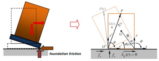
Figure 1.
The rocking of construction (left) and Housner model (right).
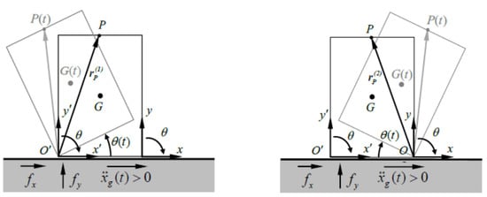
Figure 2.
The Housner rocking model with for and for [36].
In these hypotheses, the conservation of angular momentum about point O’ just before the impact and right after the impact is:
where:
- -
- I0 is the polar inertia moment relative to O;
- -
- m is the mass of the block;
- -
- R is the distance of the centre of gravity from the rotation edge;
- -
- α = arctan (b/h) is the angle that the radius R forms with the vertical direction, depending on the block’s slenderness.
By combining (1) and (2), the value of r for a rectangular block is:
The parameter r represents the energy loss during the impact. The rocking motion occurs when significant friction with the base plane prevents sliding. This model is suitable for the contact surfaces at the bell tower base. Adopting the notation of Shenton [1996], let and be the horizontal and vertical reactions at the tip O’ of the block at all times; and are the static and kinetic friction coefficients. The rocking motion occurs if:
This means that in an equilibrium configuration of the system, the angular momentum of the inertia forces is higher than the one due to the force of gravity
The rocking motion, according to the D’Alembert principle, is governed by the following set of differential equations (DEs):
where:
- -
- is the horizontal base acceleration;
- -
- are the polar inertia moments, with respect to the two points O and O’.
The rocking motion starts when , being g the gravity acceleration.
The DEs (6) present two non-linear differential equations related to the rotation motion around O and O’ and an algebraic equation involving the angular velocities in O and O’. The third equation is true at the impact instant only. The angle has been previously defined.
Introducing the signum function:
by (6), the system (5) can assume the following form:
Considering the reference systems for and for , the DEs (7) have the numerical solution represented in terms of key point P displacement.
Let be the rotation function; the position of the key point P(t) (Figure 2) can describe the rocking motion by the variation of its coordinates in R1 and R2 reference systems. The position vector at the starting time is:
so that the actual position of the key point is given by the rotation matrix :
where the rotation matrix being the orthogonal group of matrices with , is:
The acceleration can be obtained deriving (9):
Equation (11) can also be written as follows:
where the first derivative of the rotation matrix R belongs to the orthogonal group of matrices with unit determinant:
Let i be the unit vector of x axis by (12), the horizontal component of relative acceleration:
can be put in the explicit form:
The absolute acceleration :
is the sum of the base acceleration and the block one .
2.2. Sliding Motion of the Base Building
The sliding motion of a generic point of the underlying building with respect to the foundation plane occurs when the maximum horizontal force due to the static friction coefficient is reached, i.e., when:
and it is governed by the following equation:
The static friction coefficient accounts for the force required to set the block in motion, while the kinematic friction coefficient accounts for the force required to keep the block (the building) in motion and is generally .
Equations (17) and (18) hold until the actual moment at which exceeds and until the velocity at the base of the block is non-zero.
With reference to the scheme of Figure 3, the equations representing the sliding motion are:
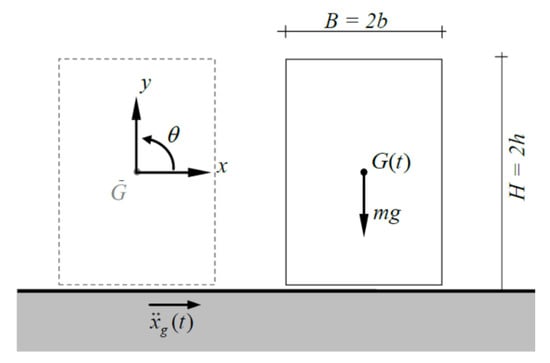
Figure 3.
The single sliding block.
Iteratively, until the relative velocity is non-zero, the second differential equation is numerically integrated. When the velocity becomes null, the block is in relative equilibrium with the base (rest) until the external force attains a value able to reactivate the sliding motion.
2.3. Combined Rocking and Sliding Motions
The combined motion analysis was recently examined in [36] and is useful in the case study. Suppose that the bell tower and the lower building are considered as rigid bodies. In this case, the combined motion describes the rocking of the upper block associated with the sliding of the lower one on the foundation plane. This hypothesis takes into account the low tensile strength of the mortar layer at the level of the tower springing [44]. Therefore, the problem is governed by the set of (5) and (9), in compact form:
where:
- -
- m1 is the mass of the bell tower
- -
- m2 is the mass of the monumental complex
- -
- M is the total mass of the complex (sum of m1 and m2)
- -
- is the signum function as defined above.
3. Application of the Proposed Method: S. Anna in Cervino Complex
3.1. Case Study Presentation
The case study is the ecclesiastical complex of S. Anna in Cervino, Caserta, reported in the following pictures, where the church, the sacristy and the bell tower are highlighted (Figure 4). These masonry aggregates are key in evaluating the vulnerability at the building scale [31,45,46,47] and urban scale [48].
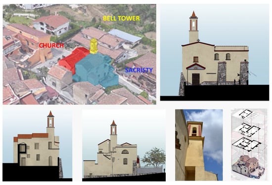
Figure 4.
The case study: the ecclesiastical complex of S. Anna in Cervino.
The bell tower has an overall height of 17.20 m (h0). Its base is placed on a pillar at an altitude of 7.40 m (h3) and is adjacent to the external wall of the sacristy for 2.30 m (h2) (Figure 5).
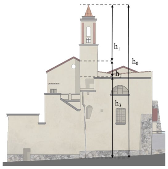
Figure 5.
The bell tower of S. Anna in Cervino.
The bell tower has three reinforced concrete curbs at different heights. The first curb, at the height of 9.85 m (h2 + h3), is considered as the base of the bell tower. Ultimately, the rocking behaviour refers to 7.35 m (h1) (Figure 5).
The global dynamic behaviour of the entire S. Maria in Cervino complex was studied by performing a detailed 3D finite element model by means of the MidasGen software [49,50] (Figure 6 and Figure 7). According to the 2018 Italian technical standards provisions [30], 170 mode shapes were considered to reach 85% of the global mass in the modal analysis.
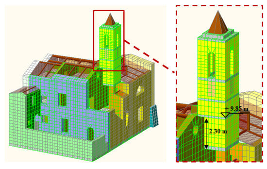
Figure 6.
FEM Model.
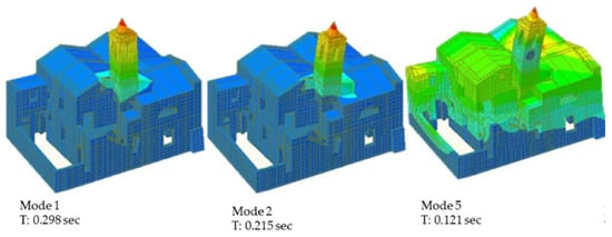
Figure 7.
Modal analysis of the building. Mode n. 1, 2 and 5.
The masonry walls and the vaulted structures were modeled using three-dimensional solid elements with 8, 6, and 4 nodes. Appropriate combinations of the different solid elements were used to obtain a refined geometry of the entire complex, respecting not only the structural and material geometry, but also the distribution of non-structural elements and openings. The masses were placed in their actual locations within the construction. The model had 18,877 nodes, 13,098 elements and a global mass of 889.0153 kN (Figure 6).
The analysis highlighted that the first and second mode shapes concerned the bell tower, which represents the most vulnerable element of the building. The first two modes activated the 6.0% (y direction) and 9.5% (x direction) of the global mass (Figure 7), respectively. This condition, therefore, requires an in-depth study of the tower, such as kinematic or rocking analysis.
3.2. Seismic Safety Assessment of the Bell Tower
The seismic safety of the bell tower alone can be evaluated in different ways, considering its response in terms of stress, strain and displacement maps from the FEM model of the global building. The FEM analysis of the bell tower alone can be performed using the floor spectrum. Mechanical models can also be used with a first-level assessment, as indicated in the Italian Guidelines for the preservation of cultural heritage [31,51,52,53,54,55]. The local out-of-plane response of the bell tower can also be studied through limit analysis, using both linear and non-linear kinematics.
This paper involves the study of the rocking of the bell tower through a dynamic analysis considering the double-block model (structure and bell tower) or the single-block for the bell tower, using the floor spectrum as reference for the base excitation.
In each of the cases listed, the only necessary parameters are the masses and the ground spectrum.
The analysis of the bell tower can be developed considering the tower itself as an isolated structural element subjected to a base motion derived from the floor spectrum, with the computational efforts due to the finite element modelling of two structural schemes: the entire building complex (to evaluate the floor spectrum) and the single bell tower to be analysed. Leaving apart the discussion about an appropriate model of the edge conditions and constraints at the tower base, in some cases the need for a detailed analysis arises after a preliminary evaluation of the tower vulnerability, performed via simplified methods.
The table below (Table 1) shows the necessary parameters to perform the FEM analyses, which are certainly more reliable, and those involved in the dynamic analyses proposed as a simplified evaluation. If only the bell tower is studied (FEM or single-block rocking model), a careful evaluation of the constraints at the base of the element and the calculation of the floor spectrum appears crucially necessary.

Table 1.
Types of model and related parameters.
The Italian Codes suggest a simplified procedure that is valid for non-structural elements and any local mechanisms. They enable taking into account of the filtering effect due to the main structure through floor spectra for computing the acceleration at the building stories [56,57].
The response and the floor spectra evaluated for the bell tower and the entire complex are reported in the following discussion.
The tower floor spectrum (Figure 8) has a maximum acceleration (a = 2.25 g), for periods between 0.1 and 0.2 s, with amplification of about four times with respect to the ground level. Therefore, the maximum amplification happens between 5 Hz and 7.98 Hz, where the last one is the fundamental vibration frequency of the bell tower.
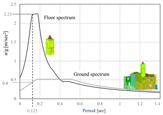
Figure 8.
Ground and floor spectra at the base of bell tower.
The dynamic analysis was developed taking into account a double-block system in which the bell tower, due to the large friction coefficient between itself and the remaining building, had the only rocking motion, while the only sliding motion of the lower structure was considered according to Equation (20).
The possible analysed motions are (see schematic representation in Figure 9):
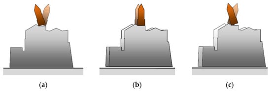
Figure 9.
Possible motions: (a) type 1; (b) type 2; (c) type 3.
- Type 1: oscillation of the bell tower with respect to the lower building perfectly fully supported on the moving foundation;
- Type 2: sliding of the entire masonry complex, including the bell tower rigidly connected to the lower building;
- Type 3: combined motion: the bell tower oscillates with respect to the building that undergoes relative displacements with respect to the foundation plane.
Figure 9a represents type 1 motion. The inertia forces determine the only rocking motion and the related equations are:
This condition represents the oscillation of the tower and holds until the condition is reached.
Figure 9b represents type 2 motion. The motion of the system is the sliding one, and the related equations are:
This condition holds until . Lower building sliding stops when .
Figure 9c represents type 3 combined motion. In this case, both the following conditions are fulfilled:
So the combined motion holds until:
4. Results
An analytical procedure was implemented in a Mathematica© routine to evaluate the results of the offered method. The analyses were carried out to investigate the displacements of the rocking bell tower in the case of the combined motion as the static and kinematic friction coefficients and the frequency of the horizontal action change. A harmonic base acceleration was considered according to the following equation:
where:
- -
- A is the oscillation amplitude;
- -
- ω is the pulse, , with f [Hz] frequency of the excitation;
The procedure implemented takes into account the following data:
- -
- m1 = 96,840.67 kN
- -
- m2 = 339 kN
- -
- 2 h = 5.80 m
- -
- 2b = 2.06 m
- -
- r = 0.9
Table 2 and Table 3 report the analysed double-block combinations, while Figure 10 and Figure 11 represent the rotation time histories ϑ(t).
Table 2.
Groups of combinations for a = 0.4 g.
Table 3.
Groups of combinations for a = 0.5 g.
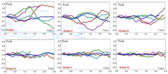
Figure 10.
Rotation time histories ϑ(t) diagrams. Groups of conditions I–VI (Table 2).
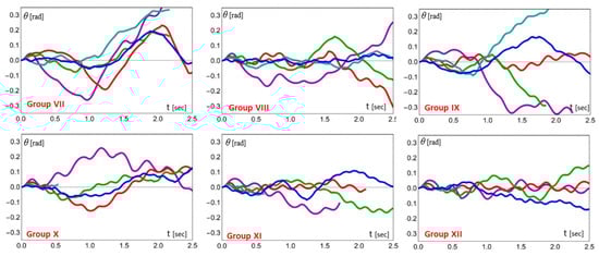
Figure 11.
Rotation time histories ϑ(t) diagrams. Groups of conditions VII–XII (Table 3).
In particular, Table 2 and Figure 10 refer to the base acceleration amplitude of 0.4 g obtained from the ground spectrum in correspondence with the bell tower period; Table 3 and Figure 11 consider the acceleration amplitude of 0.5 g, corresponding to the maximum in the ground spectrum.
As can be seen, for increasing frequency, the bell tower is more stable as the rotation amplitude decreases. With acceleration 0.4 g (Figure 10), the corresponding rotations are within acceptable ranges. In the 0.5 g graphs (Figure 11), the numerical procedure registers large rotations of the tower, compatible with overturning. Experience shows that, in the first few seconds of oscillation, when very low friction coefficients, even unrealistically low ones, are taken into account for the lower building, many bell towers do not collapse. In general, although heavily damaged, they return to their initial position.
Dynamic analyses were also performed considering the tower alone.
The base motion parameters were derived from the floor spectrum reported in Figure 8. In the single-block model, the rotation time histories of the tower due to the floor spectrum (dark grey line) are considered, while in the double-block problem those of the entire complex (light grey line) are considered. Both the one sine pulse and the continuous sine pulse excitations, together with two different combinations of the kinematic and static friction coefficients, were taken into account. For greater clarity, a summary scheme of the motion conditions is reported in Table 4.
Table 4.
Motion Conditions.
The rotation time histories for the conditions indicated in Table 4 are reported in Figure 12. As can be see, the maximum values of the tower rotations were obtained using the double-block model, even though they were, in all the examined cases, lower than the overturning angle, defined by arctan b/h = 0.35, corresponding to geometric instability. In general, the rotations obtained using the floor spectrum at the tower base were 10−1 smaller with respect to those due to the double-block model. The larger rotation angles shown in the double-block model, both in the one sine pulse and in the continuous base excitation case, confirm the reliability of the presented model for a safe preliminary analysis.
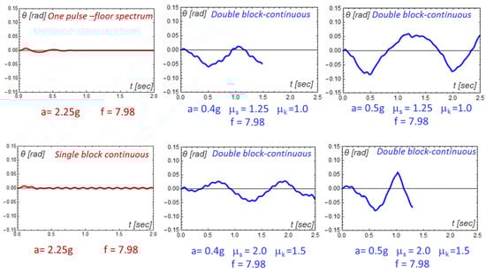
Figure 12.
Rotation histories of the tower ϑ(t) for motion conditions in Table 4.
5. Discussion and Conclusions
This paper focuses on the structural behaviour of bell towers. This type of structure, often set in ancient monumental complexes, shows a particular vulnerability to seismic action due to its pronounced slenderness and age. Different methodologies to analyse the dynamic response of bell towers exist and require knowledge of a significant number of parameters. A rigid-block-based rapid method is offered, which can provide crucial information on the dynamic response of bell towers in a first-level analysis.
The vulnerability of the bell tower of S. Anna in Cervino (Caserta, Italy), belonging to an ecclesiastical complex of several masonry buildings, was evaluated.
The dynamic behaviour of the bell tower was analysed according to several different approaches. Among them two models, one with reference to two rigid blocks (bell tower and lower building), and one to a single block (bell tower), were evidenced.
In the double-block model, the rocking of the bell tower was associated with the sliding motion of the underlying building. Different friction coefficients were considered for the contact sliding surfaces. In the single-block model, the rocking of the bell tower was considered subjected to a floor spectrum obtained after a finite element analysis of the entire complex.
The results, in terms of the time histories of the rotation angle with different ground accelerations and different couples of friction coefficients, were taken into account and discussed. It was shown that high values of excitation frequencies and friction coefficients made the bell tower stable.
Analysis with the double-block model, for which a limited amount of knowledge data is required, as shown in Table 1, appears to offer a safety advantage. Therefore, a preliminary evaluation, which is often helpful for territorial scale evaluations, could be carried out with the proposed method. Since the influence of the masonry complex was computed via its total mass and soil friction coefficients, it was shown that the presented simplified analysis can be used to make a preliminary assessment of the bell tower stability, avoiding the computational efforts needed for the finite element modelisation of the entire complex. Future work will involve improved modelling of the soil-structure interaction and impact conditions.
Author Contributions
Conceptualization, M.G. and M.M.; Methodology, M.G. and M.M.; Software, L.D.G.; Formal analysis, L.D.G. and M.M.; Resources, M.M.; Data curation, L.D.G.; Writing–original draft, M.G. and L.D.G.; Writing–review & editing, L.D.G., M.G. and M.M.; Supervision, M.M. All authors have read and agreed to the published version of the manuscript.
Funding
This research received no external funding.
Institutional Review Board Statement
Not applicable.
Informed Consent Statement
Not applicable.
Data Availability Statement
All data, models, and code generated or used during the study appear in the submitted article.
Conflicts of Interest
The authors declare no conflict of interest.
References
- Gesualdo, A.; Monaco, M. Seismic Vulnerability Reduction of Existing Masonry Buildings. Modelling of Retrofitting Techniques. In Proceedings of the COST ACTION C26: Urban Habitat Constructions under Catastrophic Events—Proceedings of the Final Conference; CRC Press: Taylor & Francis Group: London, UK, 2010. [Google Scholar]
- Gesualdo, A.; Brandonisio, G.; De-Luca, A.; Iannuzzo, A.; Montanino, A.; Olivieri, C. Limit Analysis of Cloister Vaults: The Case Study of Palazzo Caracciolo Di Avellino. J. Mech. Mater. Struct. 2019, 14, 739–750. [Google Scholar] [CrossRef]
- Iannuzzo, A.; Olivieri, C.; Fortunato, A. Displacement Capacity of Masonry Structures under Horizontal Actions via Prd Method. J. Mech. Mater. Struct. 2019, 14, 703–718. [Google Scholar] [CrossRef]
- Gesualdo, A.; Calderoni, B.; Sandoli, A.; Monaco, M. Minimum Energy Approach for the In-Plane Shear Resistance of Masonry Panels. Ing. Sismica 2019, 36, 42–53. [Google Scholar]
- Mascolo, I.; Fortunato, A.; Olivieri, C.; Gesualdo, A. Seismic Retrofitting Techniques for Existing Masonry Buildings. In Proceedings of the COMPDYN Proceedings, Athens, Greece, 28–30 June 2021; Volume 2. [Google Scholar]
- Frunzio, G.; Di Gennaro, L.; Guadagnuolo, M. Palazzo Ducale in Parete: Remarks on Code Provisions. Int. J. Mason. Res. Innov. 2019, 4, 159. [Google Scholar] [CrossRef]
- Preciado, A.; Peña, F.; Colmenero Fonseca, F.; Silva, C. Damage Description and Schematic Crack Propagation in Colonial Churches and Old Masonry Buildings by the 2017 Puebla-Morelos Earthquakes (Mw= 8.2 and 7.1). Eng. Fail. Anal. 2022, 141, 106706. [Google Scholar] [CrossRef]
- Valente, M. Seismic Vulnerability Assessment and Earthquake Response of Slender Historical Masonry Bell Towers in South-East Lombardia. Eng. Fail. Anal. 2021, 129, 105656. [Google Scholar] [CrossRef]
- Mascolo, I.; Gesualdo, A.; Olivieri, C.; Fortunato, A. On Blocks Detection in Unilateral Masonry-like Structures: A Rigid-Elastic Displacement Approach. Int. J. Mason. Res. Innov. 2022, 7, 395–405. [Google Scholar] [CrossRef]
- Minutolo, V.; Cerri, E.; Coscetta, A.; Damiano, E.; De Cristofaro, M.; Di Gennaro, L.; Esposito, L.; Ferla, P.; Mirabile, M.; Olivares, L.; et al. NSHT: New Smart Hybrid Transducer for Structural and Geotechnical Applications. Appl. Sci. 2020, 10, 4498. [Google Scholar] [CrossRef]
- Di Gennaro, L.; Damiano, E.; De Cristofaro, M.; Netti, N.; Olivares, L.; Zona, R.; Iavazzo, L.; Coscetta, A.; Mirabile, M.; Giarrusso, G.A.; et al. An Innovative Geotechnical and Structural Monitoring System Based on the Use of NSHT. Smart Mater. Struct. 2022, 31, 065022. [Google Scholar] [CrossRef]
- Montabert, A.; Mercerat, E.D.; Clément, J.; Langlaude, P.; Lyon-Caen, H.; Lancieri, M. High Resolution Operational Modal Analysis of Sant’Agata Del Mugello in Light of Its Building History. Eng. Struct. 2022, 254, 113767. [Google Scholar] [CrossRef]
- Torres, W.; Almazán, J.L.; Sandoval, C.; Boroschek, R. Operational Modal Analysis and FE Model Updating of the Metropolitan Cathedral of Santiago, Chile. Eng. Struct. 2017, 143, 169–188. [Google Scholar] [CrossRef]
- Angjeliu, G.; Coronelli, D.; Cardani, G. Development of the Simulation Model for Digital Twin Applications in Historical Masonry Buildings: The Integration between Numerical and Experimental Reality. Comput. Struct. 2020, 238, 106282. [Google Scholar] [CrossRef]
- Monaco, M.; Bergamasco, I.; Betti, M. A No-Tension Analysis for a Brick Masonry Vault with Lunette. J. Mech. Mater. Struct. 2018, 13, 703–714. [Google Scholar] [CrossRef]
- Olivieri, C.; Fortunato, A.; DeJong, M. A New Membrane Equilibrium Solution for Masonry Railway Bridges: The Case Study of Marsh Lane Bridge. Int. J. Mason. Res. Innov. 2021, 6, 446. [Google Scholar] [CrossRef]
- Montanino, A.; Olivieri, C.; Zuccaro, G.; Angelillo, M. From Stress to Shape: Equilibrium of Cloister and Cross Vaults. Appl. Sci. 2021, 11, 3846. [Google Scholar] [CrossRef]
- Angelillo, M.; Olivieri, C.; DeJong, M.J. A New Equilibrium Solut.ion for Masonry Spiral Stairs. Eng. Struct. 2021, 238, 112176. [Google Scholar] [CrossRef]
- Zizi, M.; Cacace, D.; Rouhi, J.; Lourenço, P.B.; De Matteis, G. Automatic Procedures for the Safety Assessment of Stand-Alone Masonry Arches. Int. J. Archit. Herit. 2022, 16, 1306–1324. [Google Scholar] [CrossRef]
- Zona, R.; Ferla, P.; Minutolo, V. Limit Analysis of Conical and Parabolic Domes Based on Semi-Analytical Solution. J. Build. Eng. 2021, 44, 103271. [Google Scholar] [CrossRef]
- Monaco, M.; Guadagnuolo, M. Out of Plane Behaviour of Unreinforced Masonry Walls. In Prohitech—Protection of Historical Buildings—First International Conference; CRC Press: Taylor & Francis Group: London, UK, 2009; pp. 1177–1180. ISBN 9780415558051. [Google Scholar]
- Frunzio, G.; Di Gennaro, L. The out of Plane Behaviour of Masonry Infilled Frames. J. Phys. Conf. Ser. 2021, 2090, 012148. [Google Scholar] [CrossRef]
- Gesualdo, A.; Calderoni, B.; Iannuzzo, A.; Fortunato, A.; Monaco, M. Minimum Energy Strategies for the In-Plane Behaviour of Masonry. Frat. Integrita Strutt. 2020, 14, 376–385. [Google Scholar] [CrossRef]
- Fortunato, A.; Gesualdo, A.; Mascolo, I.; Monaco, M. P-Bézier Energy Optimisation for Elastic Solutions of Masonry-like Panels. Int. J. Mason. Res. Innov. 2022, 7, 113–125. [Google Scholar] [CrossRef]
- Monaco, M.; Calderoni, B.; Iannuzzo, A.; Gesualdo, A. Behaviour of In-Plane Loaded Masonry Panels. Procedia Struct. Integr. 2018, 11, 388–393. [Google Scholar] [CrossRef]
- Zizi, M.; Chisari, C.; Rouhi, J.; De Matteis, G. Comparative Analysis on Macroscale Material Models for the Prediction of Masonry In-Plane Behavior. Bull. Earthq. Eng. 2022, 20, 963–996. [Google Scholar] [CrossRef]
- Chierchiello, G.; Gesualdo, A.; Iannuzzo, A.; Monaco, M.; Savino, M.T. Structural Modeling and Conservation of Single Columns in Archaeological Areas. In Proceedings XIV International Forum “Le vie dei Mercanti”; La Scuola di Pitagora Editrice: Napoli, Italy, 2015; pp. 2012–2020. ISBN 978-88-6542-416-2. [Google Scholar]
- Chisari, C.; Cacace, D.; De Matteis, G. A Mechanics-Based Model for Simplified Seismic Vulnerability Assessment of Masonry Bell Towers. Eng. Struct. 2022, 270, 114876. [Google Scholar] [CrossRef]
- Ceroni, F.; Casapulla, C.; Cescatti, E.; Follador, V.; Prota, A.; da Porto, F. Damage Assessment in Single-Nave Churches and Analysis of the Most Recurring Mechanisms after the 2016–2017 Central Italy Earthquakes. Bull. Earthq. Eng. 2022, 20, 8031–8059. [Google Scholar] [CrossRef]
- Ministry of Infrastructure and Transport. NTC 2018–Update of the «Technical Standards for Construction»; 2018. Available online: https://www.gazzettaufficiale.it/eli/gu/2018/02/20/42/so/8/sg/pdf (accessed on 17 January 2023).
- Guadagnuolo, M.; Nuzzo, M.; Faella, G. The Corpus Domini Bell Tower: Conservation and Safety. Procedia Struct. Integr. 2018, 11, 444–451. [Google Scholar] [CrossRef]
- Nuzzo, M.; Faella, G. The Carmine Maggiore Bell Tower: An Inclusive and Sustainable Restoration Experience. Sustainability 2021, 13, 1445. [Google Scholar] [CrossRef]
- Housner, G.W. The Behavior of Inverted Pendulum Structures during Earthquakes. Bull. Seismol. Soc. Am. 1963, 53, 403–417. [Google Scholar] [CrossRef]
- Aydin, K. The Rocking Response of an Unanchored Body Subjected to Simulated Excitation. Ph.D. Thesis, North Carolina State University, Raleigh, North Carolina, 2000. [Google Scholar]
- Gesualdo, A.; Iannuzzo, A.; Monaco, M.; Savino, M.T. Dynamic Analysis of Freestanding Rigid Blocks. Civ.-Comp Proc. 2014, 106, 1–17. [Google Scholar]
- Gesualdo, A.; Iannuzzo, A.; Monaco, M.; Penta, F. Rocking of a Rigid Block Freestanding on a Flat Pedestal. J. Zhejiang Univ. Sci. A 2018, 19, 331–345. [Google Scholar] [CrossRef]
- D’Angela, D.; Magliulo, G.; Cosenza, E. Incremental Dynamic Analysis of Rigid Blocks Subjected to Ground and Floor Motions and Shake Table Protocol Inputs. Bull. N. Z. Soc. Earthq. Eng. 2022, 55, 64–79. [Google Scholar] [CrossRef]
- D’Angela, D.; Magliulo, G.; Cosenza, E. Seismic Damage Assessment of Unanchored Nonstructural Components Taking into Account the Building Response. Struct. Saf. 2021, 93, 102126. [Google Scholar] [CrossRef]
- McCombie, P.F. Rocking of a Bell Tower—Investigation by Non-Contact Video Measurement. Eng. Struct. 2019, 193, 271–280. [Google Scholar] [CrossRef]
- Bru, D.; Ivorra, S.; Betti, M.; Adam, J.M.; Bartoli, G. Parametric Dynamic Interaction Assessment between Bells and Supporting Slender Masonry Tower. Mech. Syst. Signal Process. 2019, 129, 235–249. [Google Scholar] [CrossRef]
- Yim, C.-S.; Chopra, A.K.; Penzien, J. Rocking Response of Rigid Blocks to Earthquakes. Earthq. Eng. Struct. Dyn. 1980, 8, 565–587. [Google Scholar] [CrossRef]
- Bachmann, J.A.; Strand, M.; Vassiliou, M.F.; Broccardo, M.; Stojadinović, B. Is Rocking Motion Predictable? Earthq. Eng. Struct. Dyn. 2018, 47, 535–552. [Google Scholar] [CrossRef]
- Vassiliou, M.F.; Broccardo, M.; Cengiz, C.; Dietz, M.; Dihoru, L.; Gunay, S.; Mosalam, K.M.; Mylonakis, G.; Sextos, A.; Stojadinovic, B. Shake Table Testing of a Rocking Podium: Results of a Blind Prediction Contest. Earthq. Eng. Struct. Dyn. 2021, 50, 1043–1062. [Google Scholar] [CrossRef]
- Monaco, M.; Aurilio, M.; Tafuro, A.; Guadagnuolo, M. Sustainable Mortars for Application in the Cultural Heritage Field. Materials 2021, 14, 598. [Google Scholar] [CrossRef] [PubMed]
- Sandoli, A.; Pacella, G.; Cordasco, E.A.; Calderoni, B. PROS and CONS of Linear and Non-linear Seismic Analyses for Existing URM Structures: Application to a Historical Building. Structures 2021, 32, 532–547. [Google Scholar] [CrossRef]
- De Angelis, A.; Lourenço, P.B.; Sica, S.; Pecce, M.R. Influence of the Ground on the Structural Identification of a Bell-Tower by Ambient Vibration Testing. Soil Dyn. Earthq. Eng. 2022, 155, 107102. [Google Scholar] [CrossRef]
- De Angelis, A.; Santamato, F.; Pecce, M. Assessment of an Historical Masonry Bell Tower by Modal Testing. In Proceedings of the International Workshop on Civil Structural Health Monitoring Workshop (CSHM-8); Springer: Cham, Switzerland, 2021; pp. 219–231. [Google Scholar]
- Sandoli, A.; Lignola, G.P.; Calderoni, B.; Prota, A. Fragility Curves for Italian URM Buildings Based on a Hybrid Method. Bull. Earthq. Eng. 2021, 19, 4979–5013. [Google Scholar] [CrossRef]
- Tafuro, A. La Valutazione della Sicurezza Sismica di Complessi EcclesiasticI Il Complesso Di Sant’Anna in Cervino (CE). Ph.D. Dissertation, Università degli Studi della Campania Luigi Vanvitelli, Napoli, Italy, 2020. [Google Scholar]
- Midas Fea. Advanced Non-linear and Detail Program. Analysis and Algorithm. 1989. Available online: https://www.midasstructure.com/en/product/overview/gen (accessed on 17 January 2023).
- Ministry of Cultural Heritage and Activities. Guidelines for the Assessment and Reduction of Seismic Risk of Cultural Heritage—Alignment to New Technical Standards for Construction. Available online: https://www.soprintendenzapdve.beniculturali.it/la-soprintendenza-informa/atti-di-Address/linee-guida-per-la-valutazione-e-riduzione-del-rischio-sismico-del-patrimonio-culturale/ (accessed on 17 January 2023).
- Preciado, A.; Santos, J.C.; Silva, C.; Ramírez-Gaytán, A.; Falcon, J.M. Seismic Damage and Retrofitting Identification in Unreinforced Masonry Churches and Bell Towers by the September 19, 2017 (Mw = 7.1) Puebla-Morelos Earthquake. Eng. Fail. Anal. 2020, 118, 104924. [Google Scholar] [CrossRef]
- Bartoli, G.; Betti, M.; Monchetti, S. Seismic Risk Assessment of Historic Masonry Towers: Comparison of Four Case Studies. J. Perform. Constr. Facil. 2017, 31. [Google Scholar] [CrossRef]
- Peña, F.; Lourenço, P.B.; Mendes, N.; Oliveira, D.V. Numerical Models for the Seismic Assessment of an Old Masonry Tower. Eng. Struct. 2010, 32, 1466–1478. [Google Scholar] [CrossRef]
- Ferraioli, M.; Lavino, A.; Abruzzese, D.; Avossa, A.M. Seismic Assessment, Repair and Strengthening of a Medieval Masonry Tower in Southern Italy. Int. J. Civ. Eng. 2020, 18, 967–994. [Google Scholar] [CrossRef]
- Guadagnuolo, M.; Aurilio, M.; Tafuro, A.; Faella, G. Analysis of Local Mechanisms through Floor Spectra for the Preservation of Historical Masonries. A Case Study. In Proceedings of the COMPDYN Proceedings, Crete, Greece, 24–26 June 2019; Volume 1, pp. 1501–1513. [Google Scholar]
- Guadagnuolo, M.; Aurilio, M.; Nuzzo, M.; Faella, G. Historic Chimney Stacks: Seismic Assessment and Kinematic Analysis. J. Archit. Eng. 2023, 29, 04022037. [Google Scholar] [CrossRef]


Disclaimer/Publisher’s Note: The statements, opinions and data contained in all publications are solely those of the individual author(s) and contributor(s) and not of MDPI and/or the editor(s). MDPI and/or the editor(s) disclaim responsibility for any injury to people or property resulting from any ideas, methods, instructions or products referred to in the content. |
© 2023 by the authors. Licensee MDPI, Basel, Switzerland. This article is an open access article distributed under the terms and conditions of the Creative Commons Attribution (CC BY) license (https://creativecommons.org/licenses/by/4.0/).