Article

Experimental and Numerical Investigation of Steel- and GFRP-Reinforced Concrete Beams Subject to Fire Exposure

by
Chanachai Thongchom
1,
Linh Van Hong Bui
2,
Natthanuch Poonpan
1,
Natcha Phudtisarigorn
1,
Phuoc Trong Nguyen
3,*,
Suraparb Keawsawasvong
1 and
Saeed Mousa
4
1
Department of Civil Engineering, Faculty of Engineering, Thammasat School of Engineering, Thammasat University, Pathumthani 12120, Thailand
2
Advanced Retrofit Technology International Center, Advanced Research Laboratories, Tokyo City University, 1-28-1 Tamazutsumi, Tokyo 158-8557, Japan
3
Faculty of Civil Engineering, Ho Chi Minh City Open University, 97 Vo Van Tan, District 3, Ho Chi Minh City 700000, Vietnam
4
Faculty of Engineering, Jazan University, Jazan 706, Saudi Arabia
*
Author to whom correspondence should be addressed.
Buildings 2023, 13(3), 609; https://doi.org/10.3390/buildings13030609
Submission received: 25 December 2022 / Revised: 9 February 2023 / Accepted: 22 February 2023 / Published: 25 February 2023
(This article belongs to the Section Building Structures)

Abstract

:
This study investigates the behavior of three concrete beams reinforced with steel and GFRP bars under fire exposure. The fire tests of three beams were conducted including one control steel-reinforced concrete (RC) beam and two GFRP-RC beams. The beams were exposed to fire according to the standard fire curve ISO 834 for 3 h. The investigation parameters included the reinforcement types (i.e., steel and GFRP bars) and diameter of GFRP bars. Based on the experimental results, during fire exposure, the deflection rate of the steel-RC beam was lower than the ones reinforced with GFRP bars. The critical temperatures measured at steel and GFRP bars in the steel-RC and GFRP-RC beams were 593 °C and 300–330 °C, respectively along with the fire durations of 83 and 33–36.4 min, respectively. The different GFRP bar sizes did not affect the fire resistance process. The steel-RC beam had greater fire resistance than the GFRP-RC beams. All test specimens had a fire resistance time lower than two hours. In addition, the 2D simplified finite element method (FEM) using commercial software ANSYS was performed to predict the thermal response of the beam section. Compared with experimental results, the FE model can reasonably predict the thermal responses of the beam sections.

1. Introduction

Reinforced concrete (RC) structures are still common in the construction industry in both developing and developed countries. Many benefits of the RC structures, such as high and durable strength, shape variety, and economical value, can be clearly identified. However, when the RC structures are in use for a certain period of time, they can suffer deterioration due to various reasons, such as inefficient design, construction control, aging, and environmental impact. Much research has reported that steel-RC structures are deemed to be affected by corrosion. The aforementioned factors affect the properties of concrete following the decrease of the performance of RC structures. Permeability of air and moisture from the environment, which can cause rust in the reinforcing steel, leads to volume change and loss of bonding between steel and concrete. Engineers and researchers have paid much attention to the development of new reinforcement systems that could overcome the drawbacks of conventional steel bars.
In the past few decades, fiber-reinforced polymer (FRP) composites, which are popular in the aerospace field, have been considered for application in the construction [1,2,3,4,5]. FRP materials consist of a polymer matrix and reinforcement fibers. The fibers used as reinforcement in FRP composites can be made of various materials such as carbon, glass, aramid, or basalt, and they provide the material with its enhanced mechanical properties.
FRP materials have been increasingly used in various industries, such as aerospace, construction, and transportation, due to their unique combination of mechanical and physical properties. FRP composites offer several advantages over traditional reinforcement materials. The outstanding features of FRP make them lightweight and easy to install. The anticorrosion and chemical resistance of the FRP composites require little maintenance and are highly durable and four times lighter than traditional reinforcement materials [6,7,8]. The FRP composites can be used for all components of the structures, including slabs, columns, and beams [8,9,10,11,12]. Conversely, as summarized in the studies [11,12,13], FRP behaves linearly until rupture; thereby, the elements with FRP reinforcement may experience a brittle and sudden failure. Recently, several studies proposed the hybrid use of steel and FRP for reinforcing the concrete members and proposed extra strengthening of FRP to existing steel-RC structures. FRP reinforcement has a higher tensile strength compared to steel rebars. A number of research works indicated that the beams with FRP reinforcement had a higher load-carrying capacity than the those with conventional steel reinforcing bars [5,14,15,16,17].
Aside from the above-mentioned impacts, fire is one of the most unexpected threats to building structures. When a fire accident occurs, it will cause a lot of damage to both the life and property of the building occupants [18,19]. Regardless of whether the fire occurred intentionally or unintentionally, when the fire has occurred, it will spread to other areas rapidly. When the fire is exposed to the FRP-reinforced concrete structures, it affects the mechanical properties of the concrete and reinforcements. When exposed to high temperatures, the concrete can undergo physical and chemical changes that can weaken its structure and reduce its strength. At low temperatures, the concrete may only experience surface cracking and spalling, which can lead to the loss of the surface layer. As the temperature increases, the concrete can undergo thermal expansion and contraction, which can cause the concrete to crack and delaminate. At even higher temperatures, the hydration process of the concrete can be reversed, leading to the release of water and the formation of steam. This may cause the concrete to expand and spall, leading to further loss of material. The properties of concrete, such as its compressive and tensile strength, are reduced as a result of fire exposure. In general, concrete will spall after exposure to temperatures between 200 °C and 325 °C. The explosive spalling of concrete appears to coincide with high pore pressure buildup and a high thermal gradient [20]. When the concrete is exposed to fire at 300 °C, the strength reduction will be in the range of 15–40% [21]. When FRP is exposed to fire, FRP reinforcements can undergo significant changes in their mechanical properties, such as tensile strength and modulus of elasticity. As the temperature increases, the FRP rebar can soften and lose its strength. Additionally, the fire can cause thermal degradation of the polymer matrix, leading to the release of toxic gases and the formation of cracks and voids. This can further reduce the strength and durability of the FRP rebar, making it more susceptible to corrosion and other forms of degradation. In particular, when the FRP is exposed to temperatures at the glass transition level ( T g ), the resin matrix of FRP is affected to induce a small crack and to soften the FRP surface. At higher glass transition temperature levels, the softness of the FRP occurs more quickly. When the FRP is exposed to the critical temperature ( T c r ), the tensile strength of the FRP is reduced by 50% [19]. This can be a significant concern in high-temperature fire scenarios, as the fire can quickly spread and cause extensive damage to the building or structure.
Therefore, it is extremely important to focus on the fire resistance of a building structure as its structural integrity might be the last line of defense, as stated in the works of [19,22,23,24,25,26,27]. Fire resistance is a critical factor in the design and construction of buildings and structures. The fire resistance time of FRP-reinforced concrete beams refers to the amount of time that a concrete structure can withstand high temperatures without collapsing or losing its structural integrity. The fire resistance time of a concrete structure is crucial in ensuring the safety of the building and its occupants. The fire resistance time of GFRP-reinforced concrete beams is influenced by a number of factors including the properties of the concrete, the thickness of the concrete covering, the heating rate, the cooling rate, and the properties of the FRP reinforcement. The properties of the concrete, such as its compressive strength, permeability, and water-to-cement ratio, play a significant role in determining its fire resistance time. The thickness of the concrete covering is also important, as thicker concrete provides more insulation and protection against high temperatures. The heating and cooling rates of the concrete can also have a significant impact on its fire resistance time.
The progress of the application of FRP for construction requires an understanding of the behavior of the FRP-reinforced structures under extreme actions and agents. Various types of FRP have been applied and studied, in which the common FRP types are carbon FRP (CFRP), glass FRP (GFRP), and aramid FRP (AFRP). The benefit of GFRP compared to other FRPs is that the GFRP has low elastic modulus but high rupturing strain. This behavior may provide better ductility of the GFRP-RC members in comparison to the CFRP/AFRP-RC elements. Therefore, the studies of the behavior of GFRP-RC beams under fire conditions are necessary to gain insights into the safety of building occupants. The present study experimentally and numerically investigates the responses of two concrete beams reinforced with GFRP bars (GFRP-RC beams) and one concrete beam reinforced with steel reinforcement bars (steel-RC beam) subjected to fire exposure. The thermal responses of the steel-RC beams and GFRP-RC beams exposed to a standard fire curve for three hours are investigated. The fire resistance time based on the critical temperature for both steel-RC beams and GFRP-RC beams are examined. The temperature and time dependencies among beams are assessed. Additionally, the effects of different GFRP bar sizes on the thermal behavior of RC beams are evaluated. Conversely, the temperature distribution along the beam section obtained from the fire tests is compared with that simulated by a simplified two-dimensional finite element method (2D FEM) using the numerical software ANSYS 15.0.

2. Materials and Methods

2.1. Tested Beam Specimens

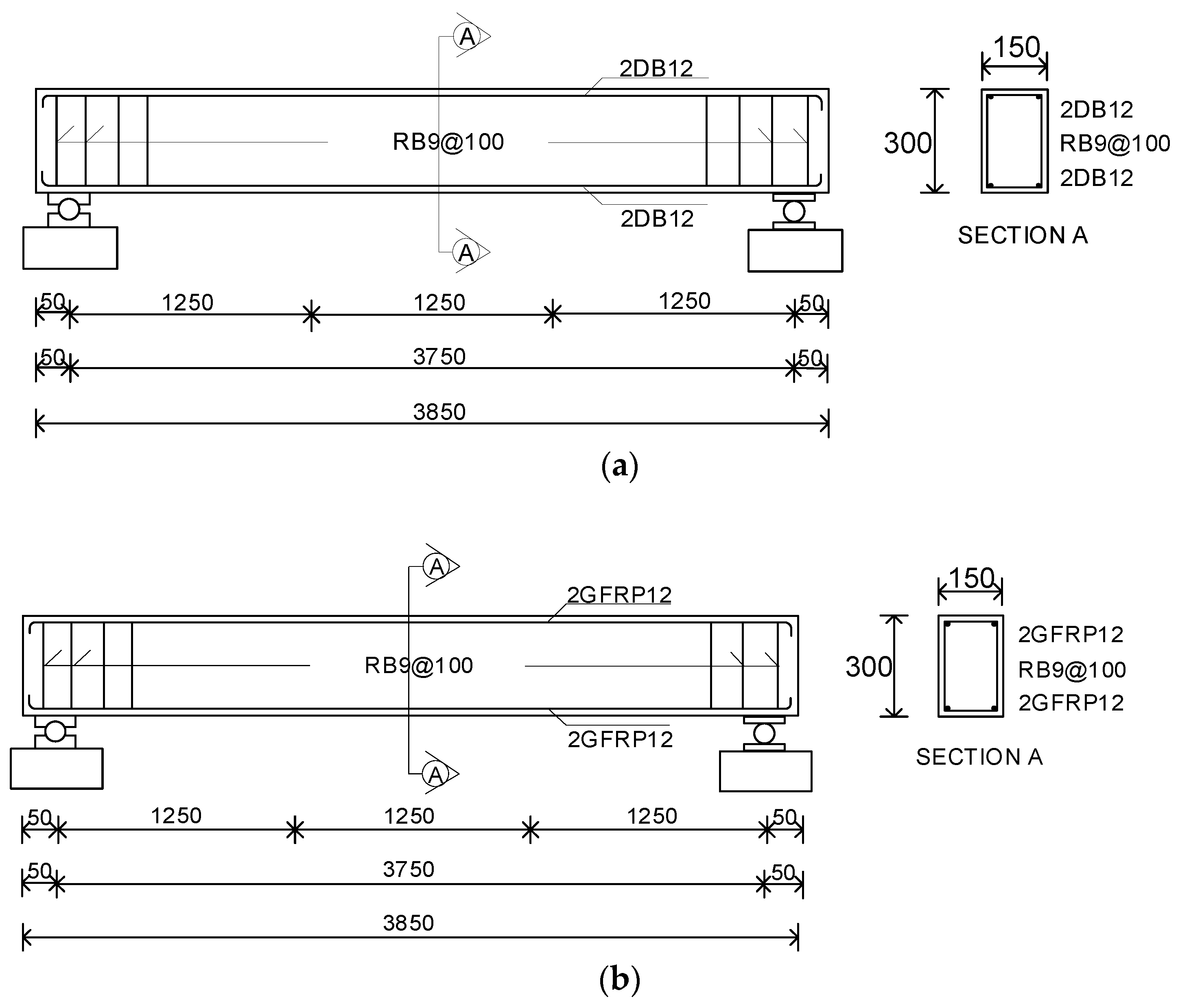
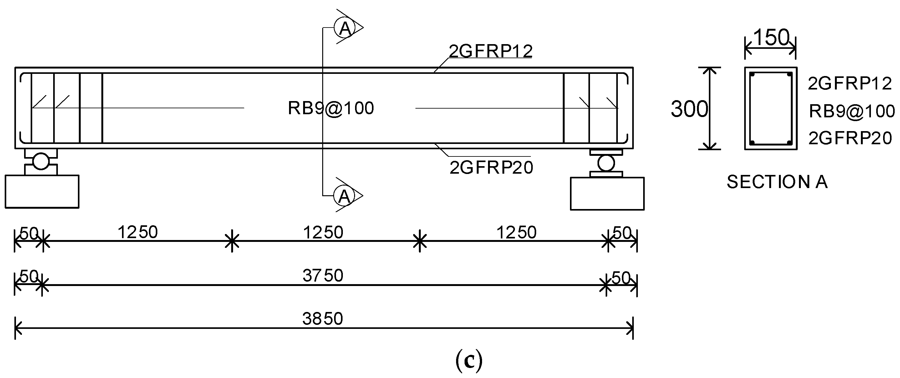
Three full-scale beams were tested in this study. The purposes of the tests were to compare the behavior of RC beams reinforced with GFRP bars under fire exposure considering the different amount of GFRP reinforcement. An overview of this study is shown in Figure 1. The beams were 3850 mm long, 150 mm wide, and 300 mm high. The length of the beams from support to support were 3750 mm. The concrete cover thickness was 25 mm, while the stirrups in all beams were made from RB9 and spaced at 100 mm. The details of the beams are shown in Table 1. The beam RC12 was the control beam, which includes two tensile steel bars and two compressive steel bars. Meanwhile, the beams BF12 and BF20 had two GFRP12 bars and two GFRP20 bars for reinforcing the bending zone, respectively. These beams had two GFRP12 for compressive reinforcement. The beam configurations are demonstrated in Figure 2.

2.2. Material Properties

Ready-mixed concrete was used in this experimental program. The average compressive strength of the concrete from three standard cylinder specimens (ASTM C39/C39M [28]) was 28 MPa with standard deviation of 0.43. The three samples of steel reinforcement were tested under tensile loading according to ASTM A370 [29]. The steel reinforcements DB12 (Standard deformed bars 40, SD40) had a yield strength of 466 MPa, an ultimate strength of 540 MPa, and an elastic modulus of 210 GPa. The steel stirrups RB9 (Standard round bars, SR24) had a yield strength of 270 MPa, an ultimate strength of 410 MPa, and an elastic modulus of 206 GPa. Five GFRP bars were also tested under tensile loading according to ASTM D7205/D7205M [30]. The GFRP bars with 12 mm diameter had a tensile strength of 851 MPa and an elastic modulus of 45 GPa. In addition, the GFRP bars with 20 mm diameter had a tensile strength of 935 MPa and an elastic modulus of 45 GPa. The mechanical properties of reinforcements are summarized in Table 2. The standard composition of steel reinforcement typically consists of 98.6% to 99.2% iron (Fe), 0.15% to 0.30% carbon (C), 0.60% to 1.20% manganese (Mn), and 0.15% to 0.35% silicon (Si), with a maximum of 0.05% sulfur (S) and phosphorus (P). Additionally, trace amounts of chromium (Cr), nickel (Ni), and molybdenum (Mo) are included, typically in amounts less than 0.10%. Table 3 shows the chemical composition of both RB9 and DB20 steel reinforcements provided in the TIS guidelines [31,32].
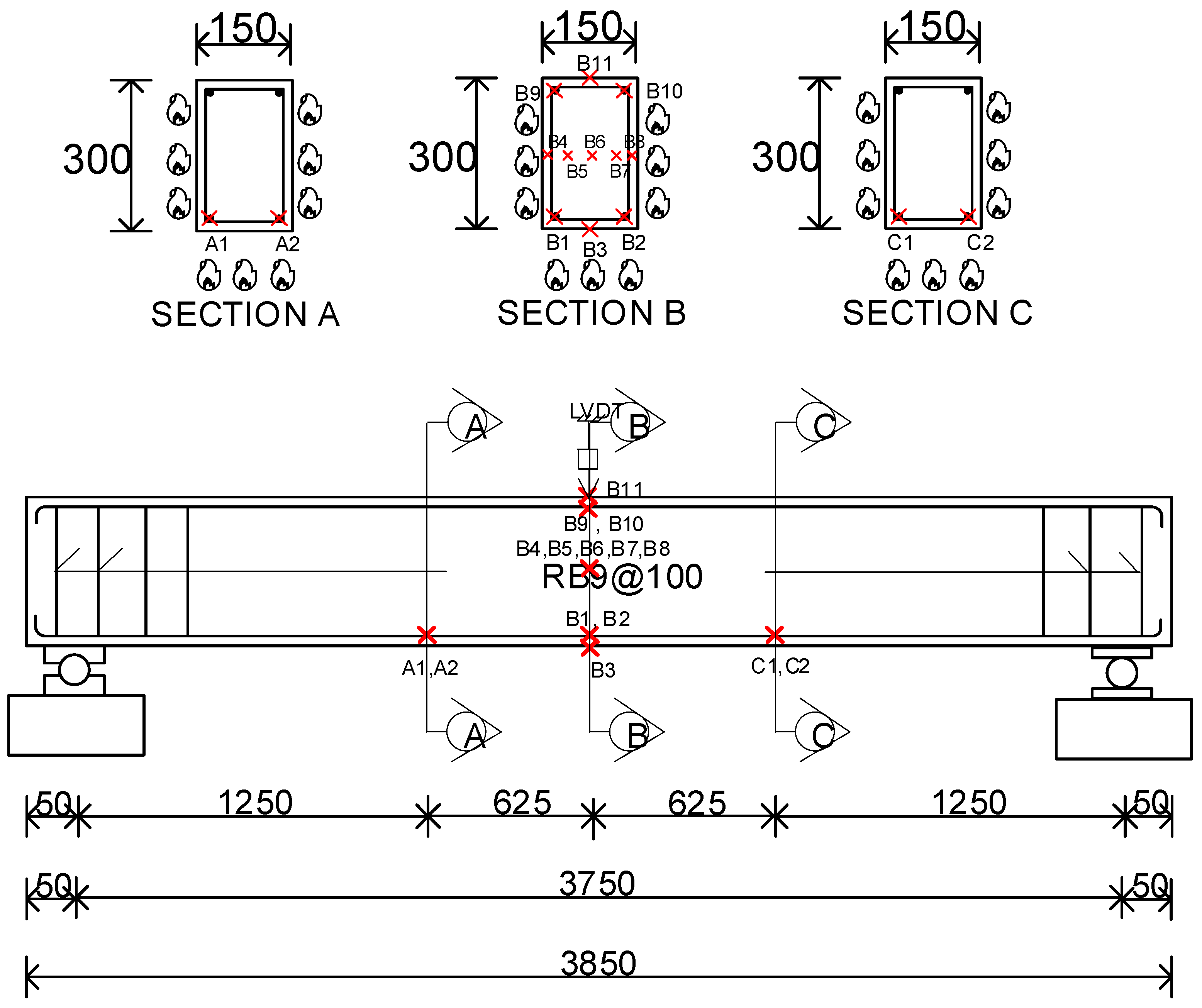
During fire test, a linear variable differential transformer (LVDT) was installed in the center of the beams of all test samples to measure the deflection of beams during a fire. The temperature gauges (thermocouple) were glued on positions A, B, and C of each beam to measure the temperature inside the beam cross-section. The details of installation of LVDTs and thermocouples are shown in Figure 3.
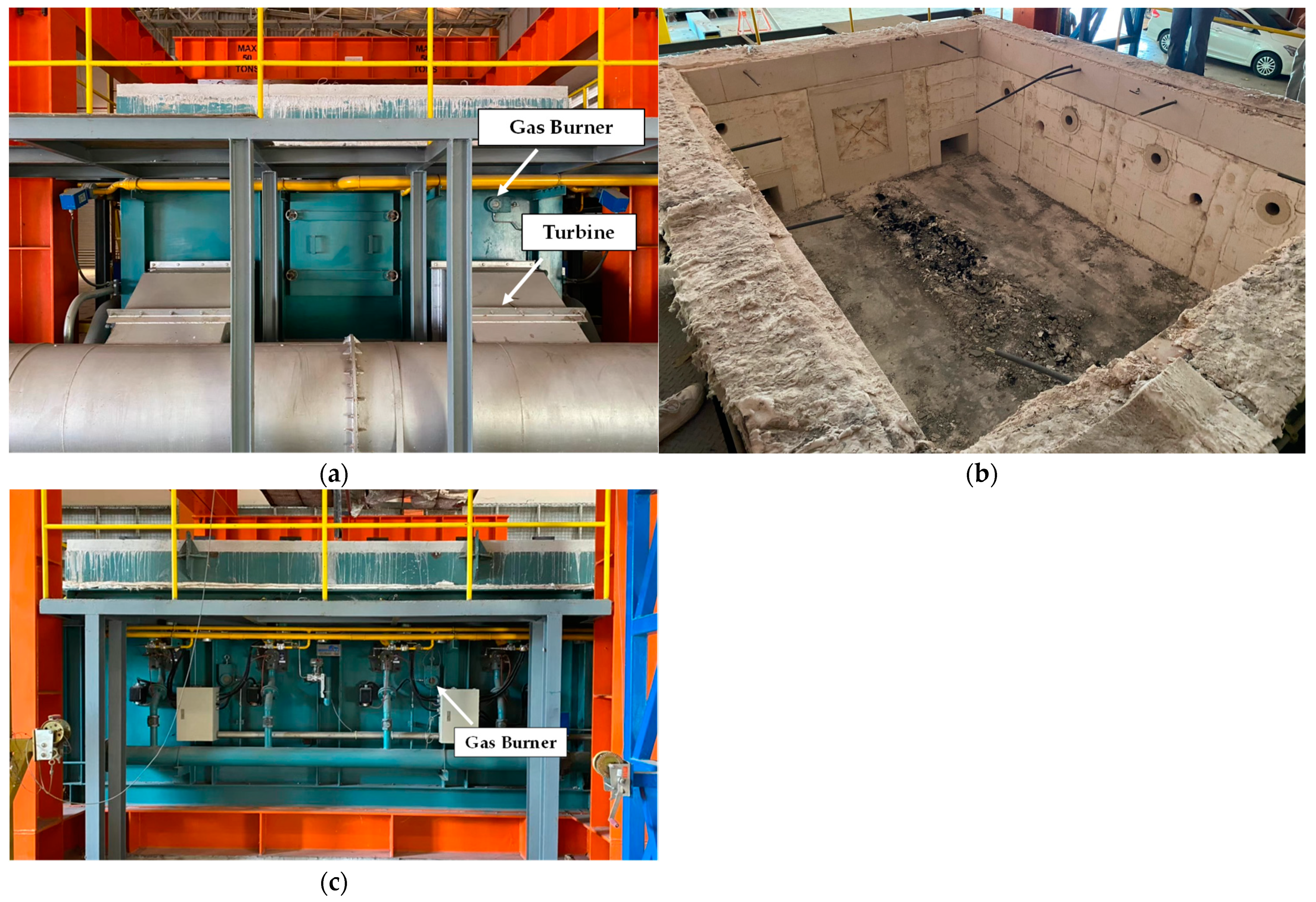
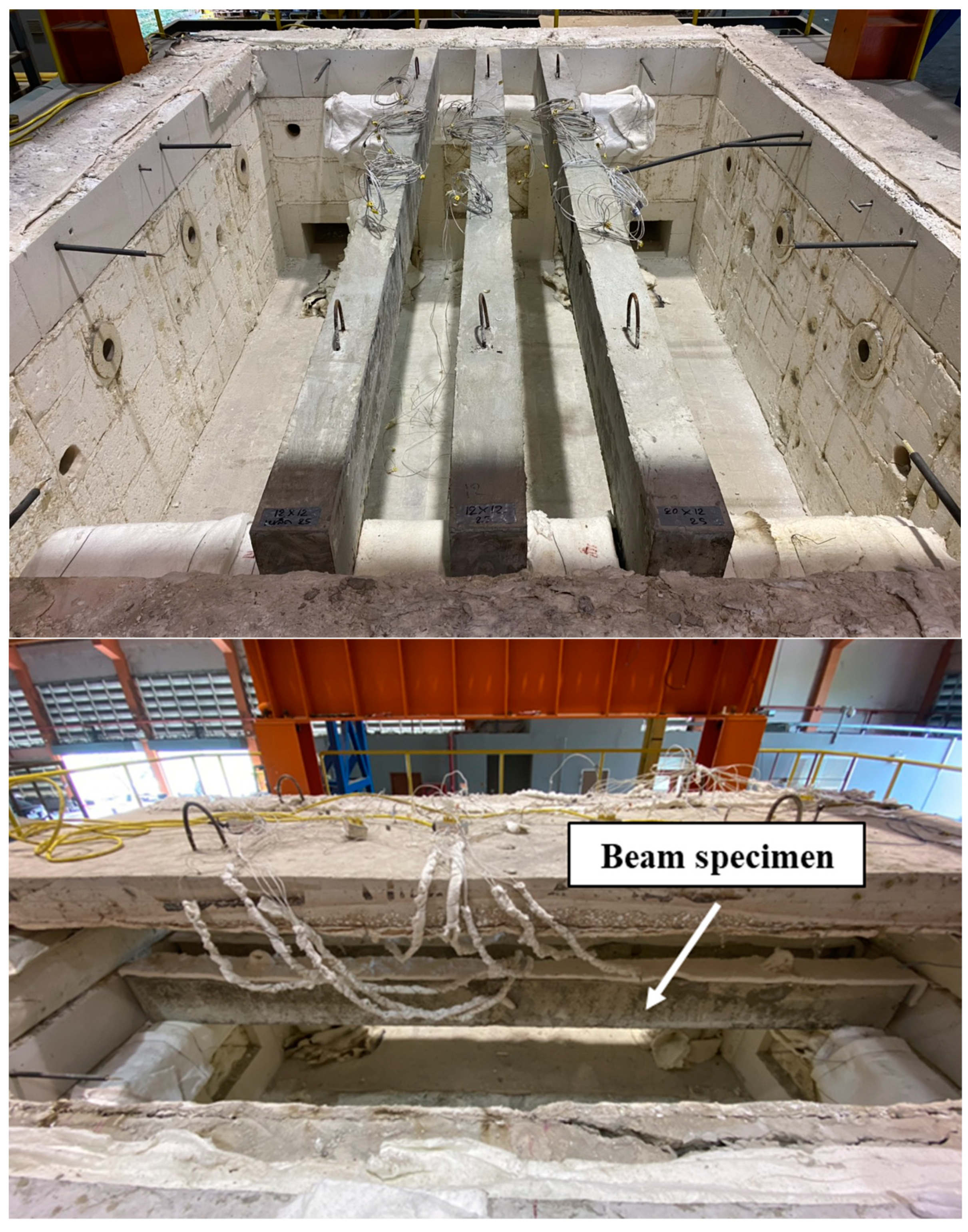
In this test, all sample beams are exposed to fire. The dimensions of the furnace are 3500 mm width, 4500 mm length, and 1600 mm depth. The details of the front, top, and side cross-sections are shown in Figure 4a, Figure 4b, and Figure 4c, respectively, and the photographs of the furnace front, top, and sides are shown in Figure 5a, Figure 5b, and Figure 5c, respectively.
For the fire resistance test, the RC12, BF12, and BF20 specimen beams were exposed to fire in accordance with ISO 834 [33] simultaneously for all three samples until the beams failed under critical temperature. This means when the temperatures at the location of the reinforcing bar and the GFRP bar reached 593 °C [34,35] and 300–330 °C [27,36], respectively. The installation of the sample beam in the furnace and the thermocouple signal installation are shown in Figure 6.

3. Results and Analyses

3.1. Distribution of Temperature along the Beam Section

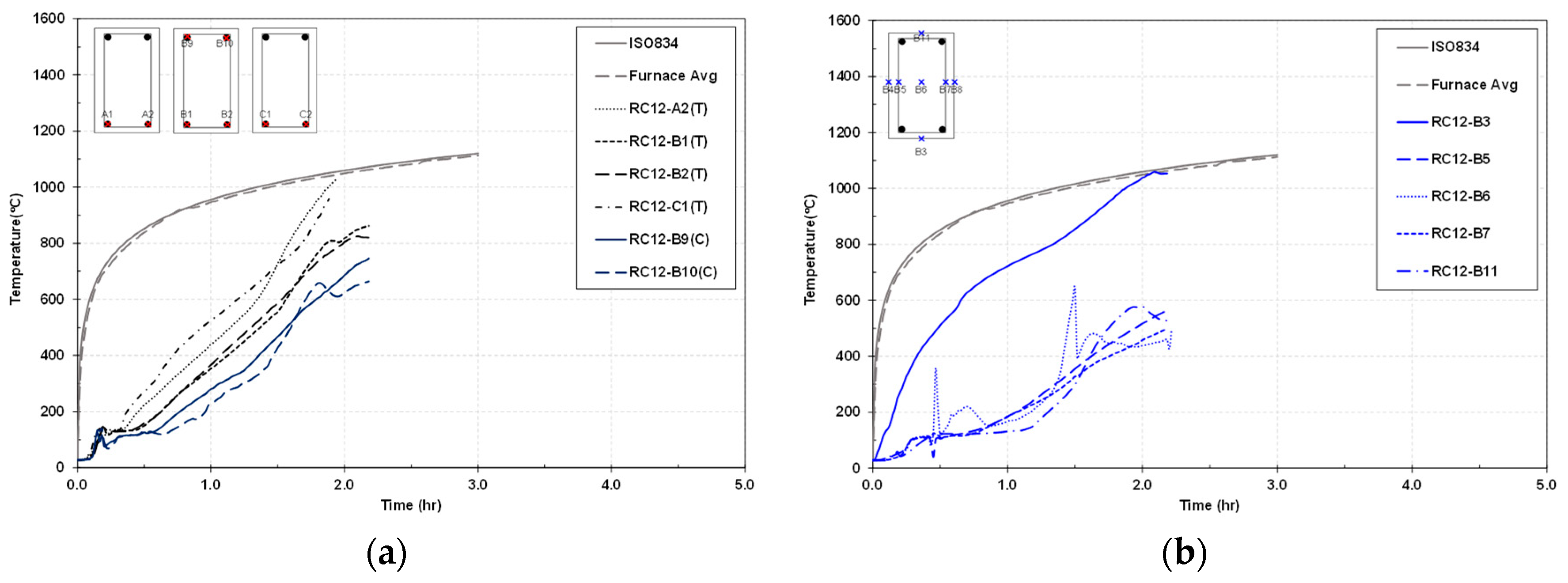
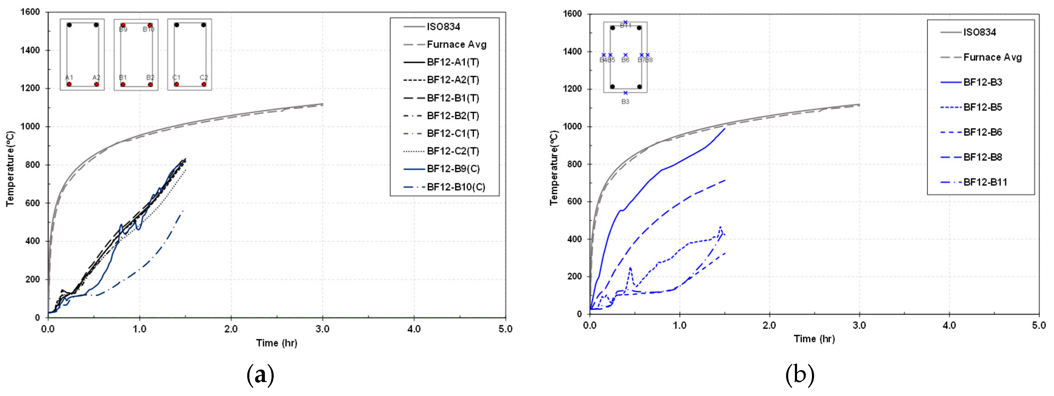
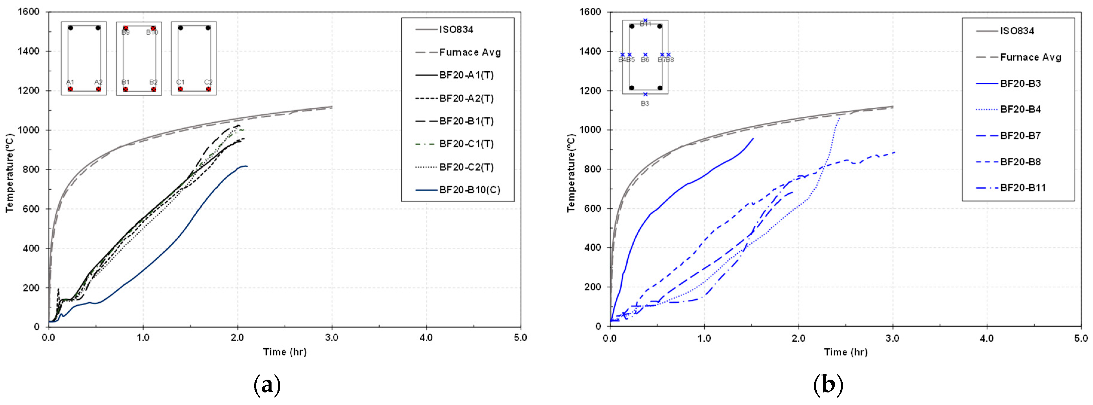
In Figure 7, Figure 8 and Figure 9, the temperature distribution along the beam sections in the beams RC12, BF12, and BF20, measured by the thermocouples, shows that the temperature exposed to the beam components increased rapidly with a nonlinear relationship to time. It can be seen that the temperature measured at the beam bottom was higher than that at the beam center and top. This is due to the fact that the fire was set to start exposing the beam from the bottom. Generally, the temperature at the beam center (positions B4, B5, B6, B7, and B8) was higher than that at the concrete bottom and top of the beam. However, before 1.5 h, the temperature was found to be slightly higher than the beam top at position B11 because the top of the beam was covered with ceramic fiber to prevent fire exposure. After 1.5 h, the temperature at B11 was higher than the temperature at the center of the beam. A possible reason is that the increase in temperature, and the increase in deflection, led to the top of the beam becoming heavily exposed to fire. The aforementioned observations imply that the material properties of tension reinforcement (steel or GFRP) did not affect the trend of the temperature distribution under fire in the long-span RC beams. Effects of various parameters on the performance of beams under fire are shown in the following sections.

3.2. Effects of GFRP and Steel

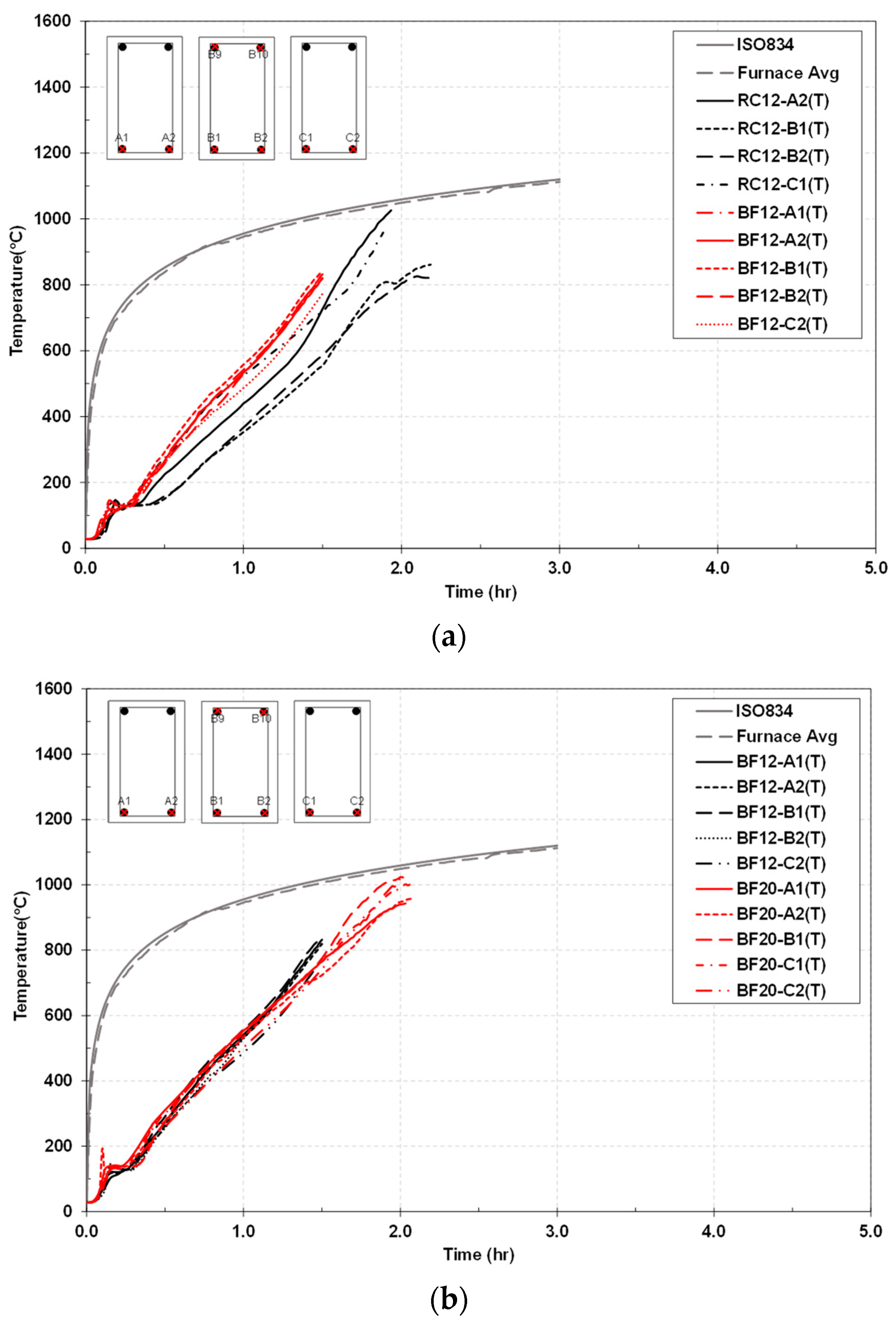
Figure 10a,b presents the comparison in the temperature versus time responses at the tension reinforcement layers between RC12 (beam reinforced with steel tensile bars) and BF12 and BF20 (beams reinforced with GFRP tensile bars). Obviously, Figure 10a implies that with the same bar diameter, the beam with steel longitudinal reinforcement (RC12) provided a higher maximum temperature than the beam with GFRP tensile bars (BF12). Indeed, the maximum temperatures measured in steel and GFRP tension reinforcement in those two beams were over 1000 and over 800 °C, respectively. At the same temperature level, the beam with GFRP bars exhibits an earlier time than the beam with steel bars. This is attributable to the fact that the thermal properties of steel in terms of the thermal conductivity, specific heat, and coefficient of thermal expansion have better fire resistance compared to those of GFRP. In Figure 10b, the temperature‒time performance of the beam with bigger GFRP bars is greater than that of the beam with smaller GFRP bars. a possible reason is that the larger GFRP bar size provided the greater thermal capacity to increase fire resistance. To obtain 1000 °C at the tension reinforcement, the beam reinforced by GFRP bars with 20 mm diameter furnished the same temporal behavior as the beam reinforced with steel bars with 12 mm diameter. As seen in Figure 10a,b, under the increase in temperature, all specimens failed at approximately 2 h or less.

3.3. Fire Resistance

Table 4 presents the times when the thermocouples obtained critical temperatures. Note that the critical temperatures for steel and GFRP bars were obtained from the combined thermal and tensile tests. As a result, it was found that the thermocouples at positions A2, B1, B2, and C1 in the steel-RC beam (RC12) reached critical temperature (Tcr = 593 °C) at 80, 90, 91, and 71 min, respectively. Meanwhile, the thermocouples in the GFRP-RC beams reached critical temperature at around 31‒39 min. This could be due to the early deterioration of the GFRP bars under fire exposure. The steel-RC beam performed with better fire resistance than the GFRP-RC beams, while the GFRP-RC beam with larger GFRP tension bars provided a longer fire resistance time. According to fire resistance based on critical temperature [34], all beams failed under fire at three hours or less. The main reason is that the long span of the beams could increase deformation, which induces more microcracks. This condition would accelerate the exposure of fire to the reinforcement, leading the premature failure of the beams.

3.4. Failure of Beam under Fire

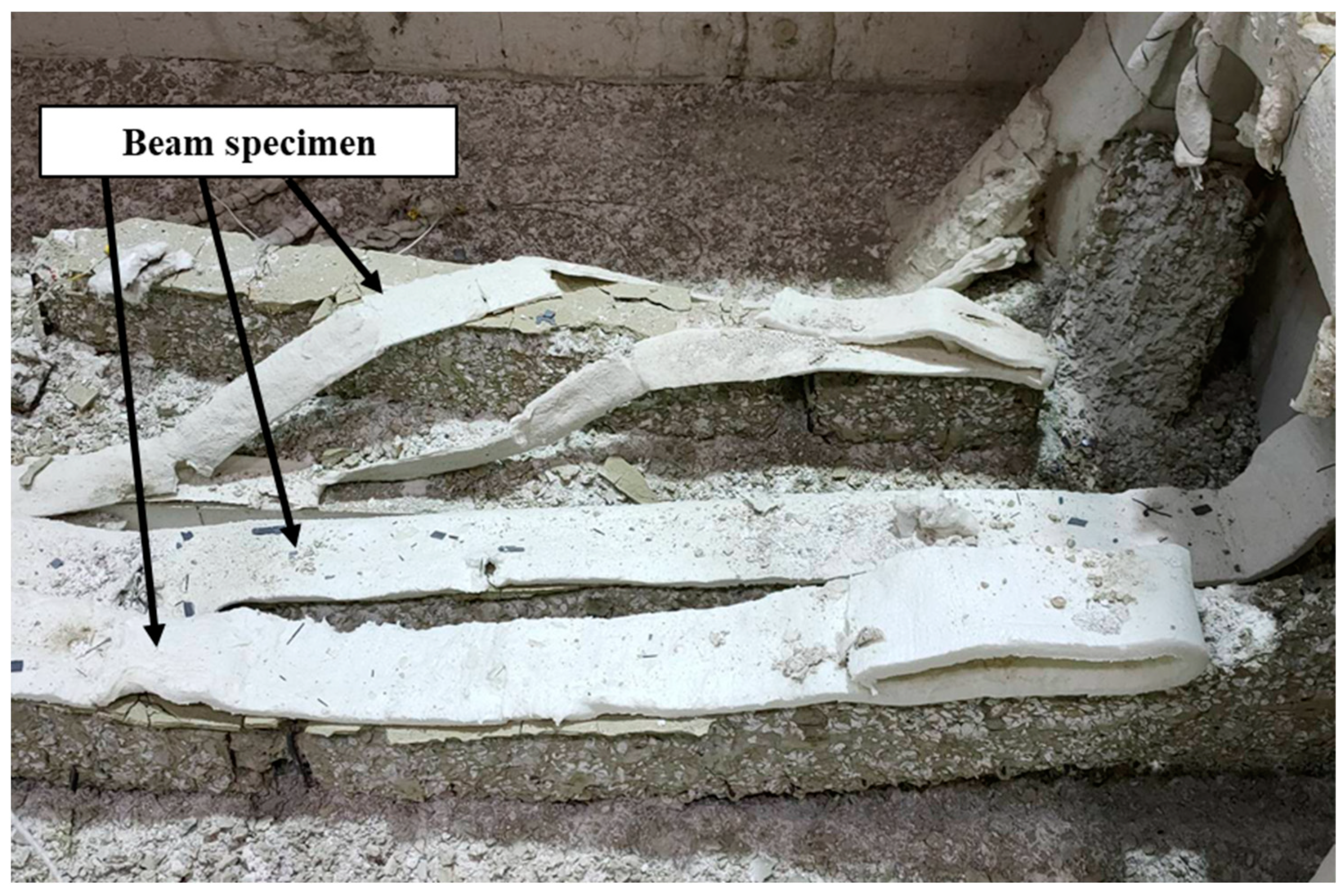
Figure 11 shows the failure of all beams under fire process. It can be seen that all beams collapsed and fell down to the kiln floor. At failure completion, heavy damage with large cracks and spalling occurred. The primary causes are (1) the long span of the beams provides large deformation that speeds up the failure process due to the quick aggressiveness of fire affecting the reinforcement and (2) under fire, the concrete is spalled and the melting of steel reinforcements might decrease the bond strength between steel and concrete, leading to cracks in concrete. To prevent the premature failure of concrete structures exposed to fire, the recommended methods from previous works are (1) using lightweight aggregates [37] and (2) using fire-resistant coatings such as intumescent coatings, etc. [38].

3.5. 2D Thermal Analysis

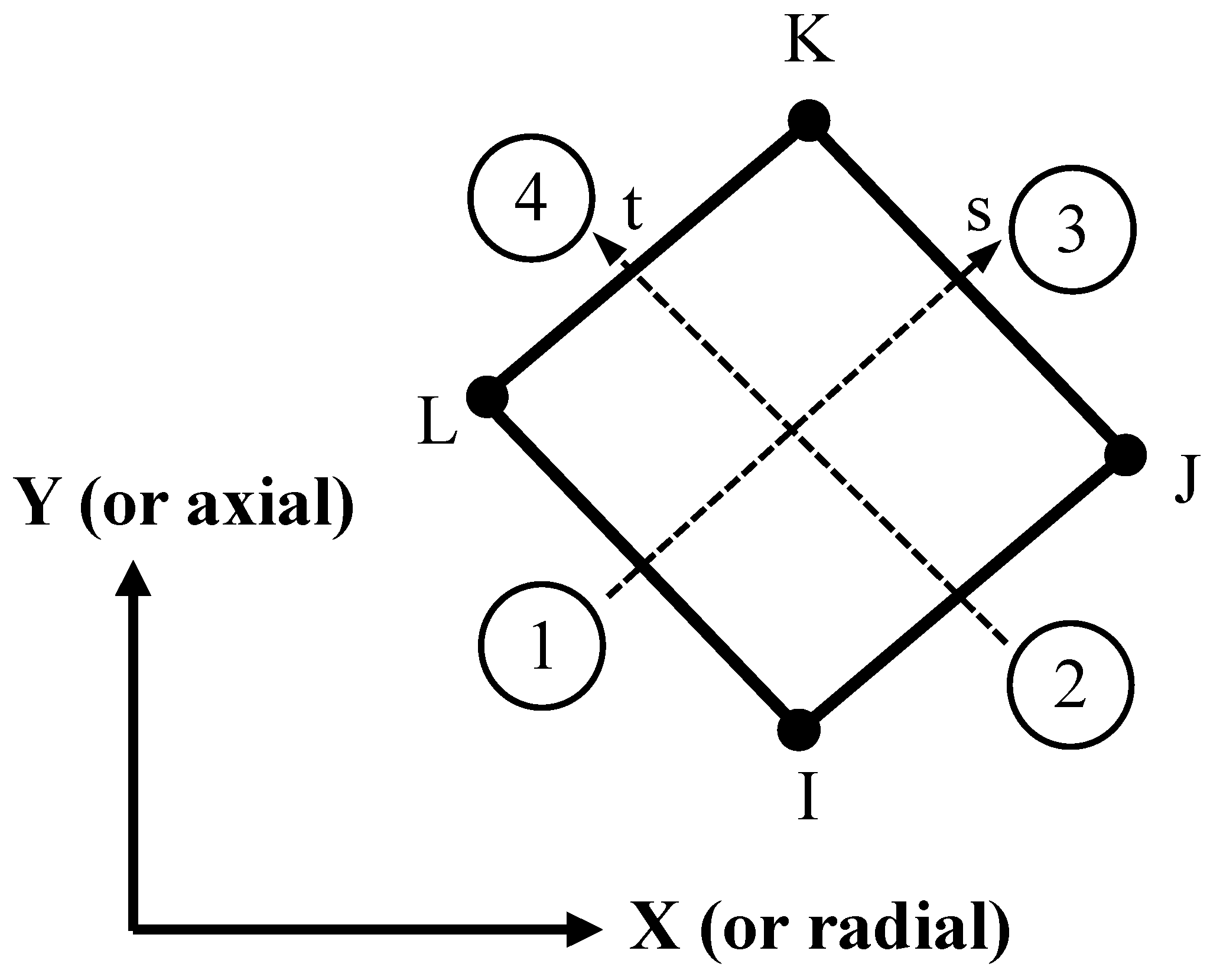
The finite element model for temperature analysis was conducted using a 2D finite element analysis using the ANSYS program. The concrete element was modeled using PLANE55 [39]. It is a planar element or is an axially symmetrical annular element with 2D thermal conductivity. The element has four nodes with temperature-independent degrees at which each element node is applicable to thermal analysis of 2D, steady state, or transient [39]. Figure 12 represents the element of PLANE55.
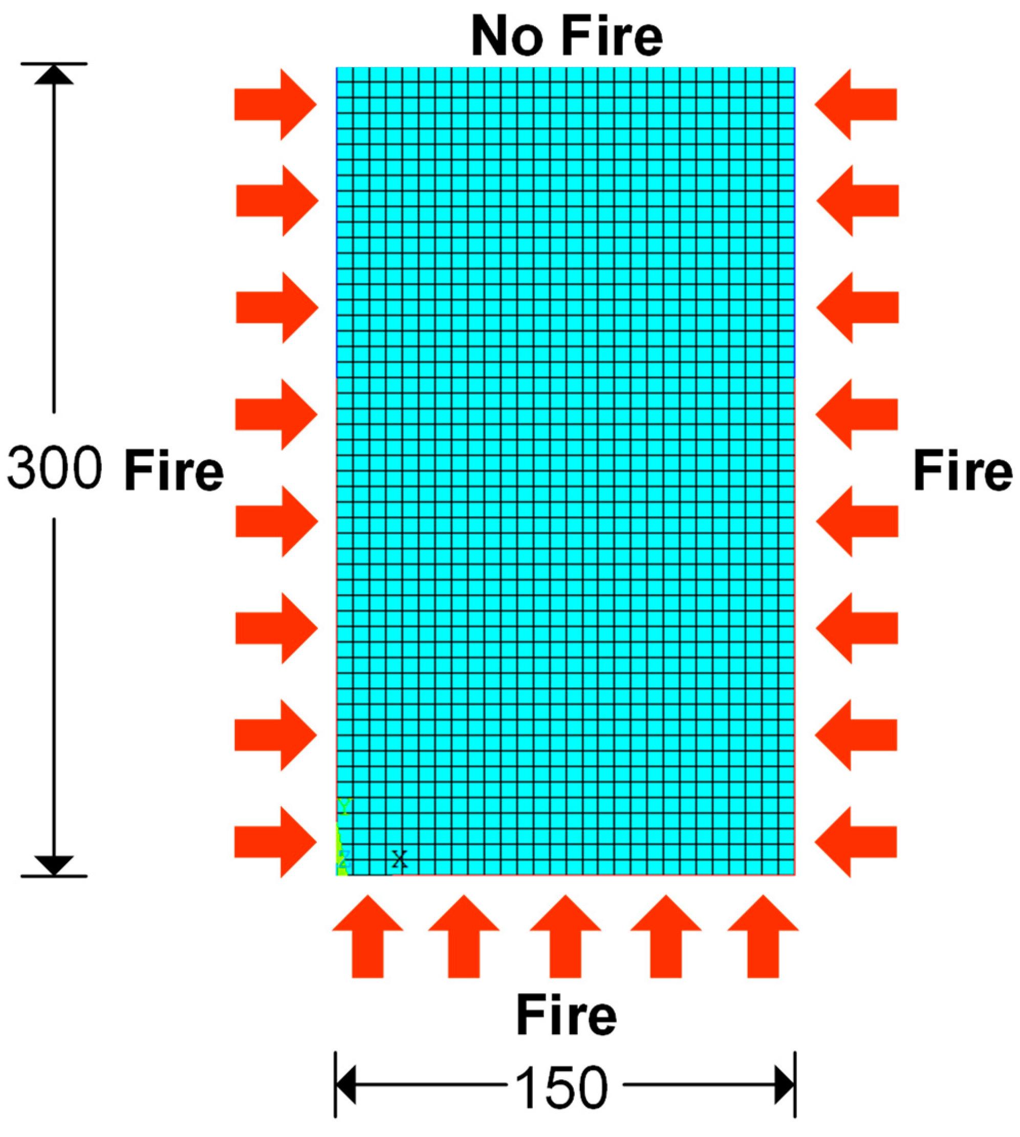
Figure 13 shows a simplified 2D beam section for heat transfer analysis. Three sides of the beam were directly exposed to fire and one was unexposed. Based on the assumption that the reinforcements did not significantly influence the temperature distribution in the beam section, they were not included in the 2D FE model [40,41]. In this study, the carbonate aggregate concrete was assumed. The thermal properties were needed in the thermal analysis. In this study, the thermal properties of concrete were proposed by Eurocode2 [41] and included thermal conductivity, specific heat, and density.
The thermal conductivity ( k ) properties of normal strength concrete are proposed to be between the upper limit and the lower limit in the temperature range 20–1200 °C since concrete is a composite material, as shown in Equation (1):
k = { 2.0 0.2451 ( T c 100 ) + 0.0107 ( T c 100 ) 2 for   upper   limit 1.36 0.136 ( T c 100 ) + 0.0057 ( T c 100 ) 2 for   lower   limit
The specific heat of concrete ( c c ) normally varies with the moisture content in the concrete and the temperature. For concrete in a dry state (moisture 0%), the temperature range of 20–1200 °C is proposed as shown in Equation (2):
c c = 900 for   20   ° C T c 100   ° C c c = 900 + ( T c 100 ) for   100   ° C   <   T c 200   ° C c c = 1000 + ( T c 200 ) 2 for   200   ° C   <   T c 400   ° C c c = 1100 for   400   ° C < T c 1200   ° C  
The density of concrete ( p c ) varies with temperature, with a decreasing value due to internal water loss of the concrete as shown in Equation (3). In this work, the concrete density of 2400 kg/m3 is used.
p c = p c , R T for   20   ° C T c 115   ° C p c = p c , R T ( 1 0.02 T c 115 85 ) for   115   ° C   <   T c 200 ° C p c = p c , R T ( 0.98 0.03 T c 200 200 ) for   200   ° C   <   T c 400   ° C p c = p c , R T ( 0.98 0.03 T c 200 200 ) for   400   ° C < T c 1200   ° C  
An average furnace temperature was applied as convection on lines (section sides) with convection film coefficient values of 25 W/m2·K for exposed surface and 9 W/m2·K for unexposed surface [41,42,43,44].

3.6. Results and Discussion

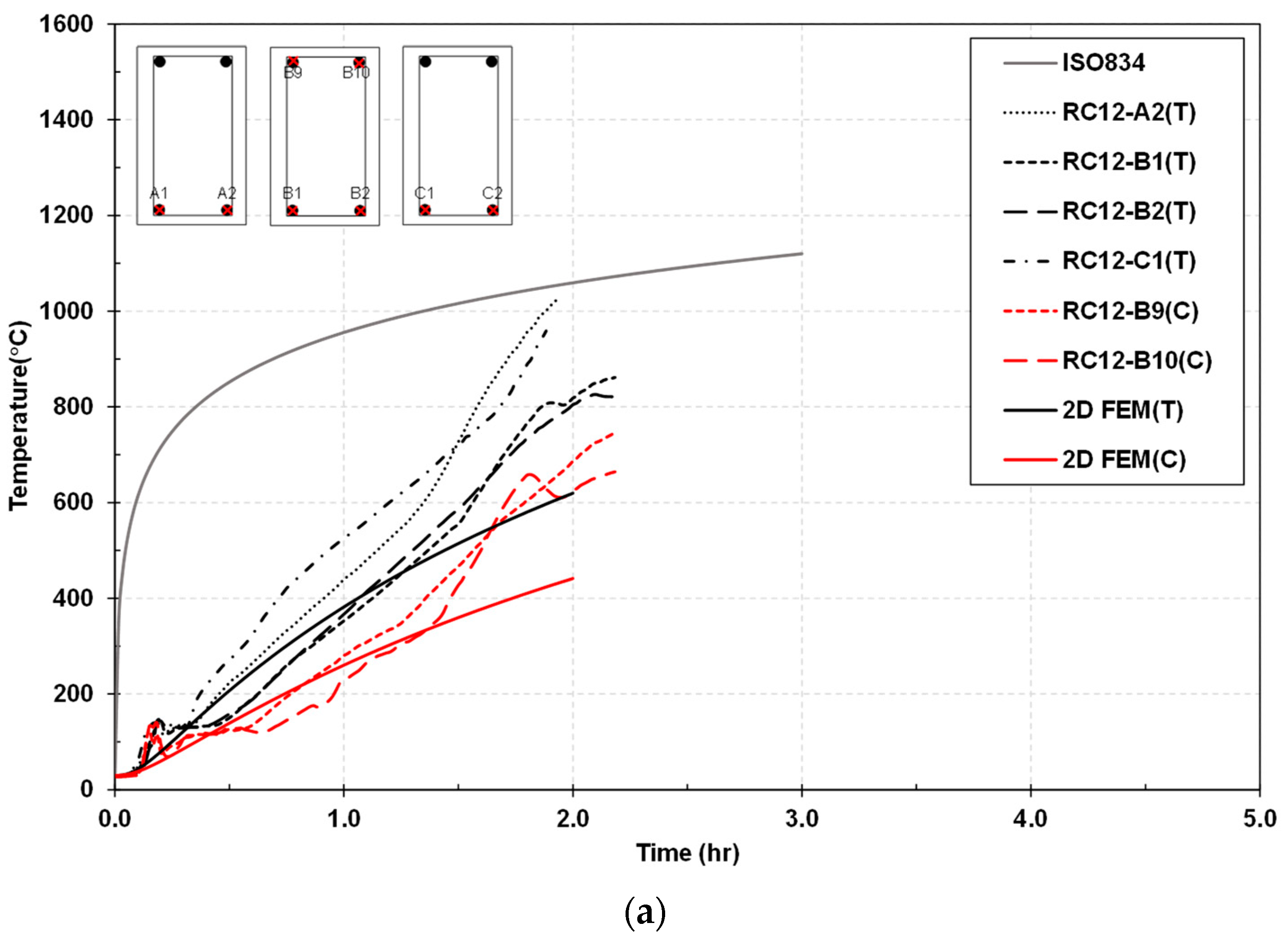
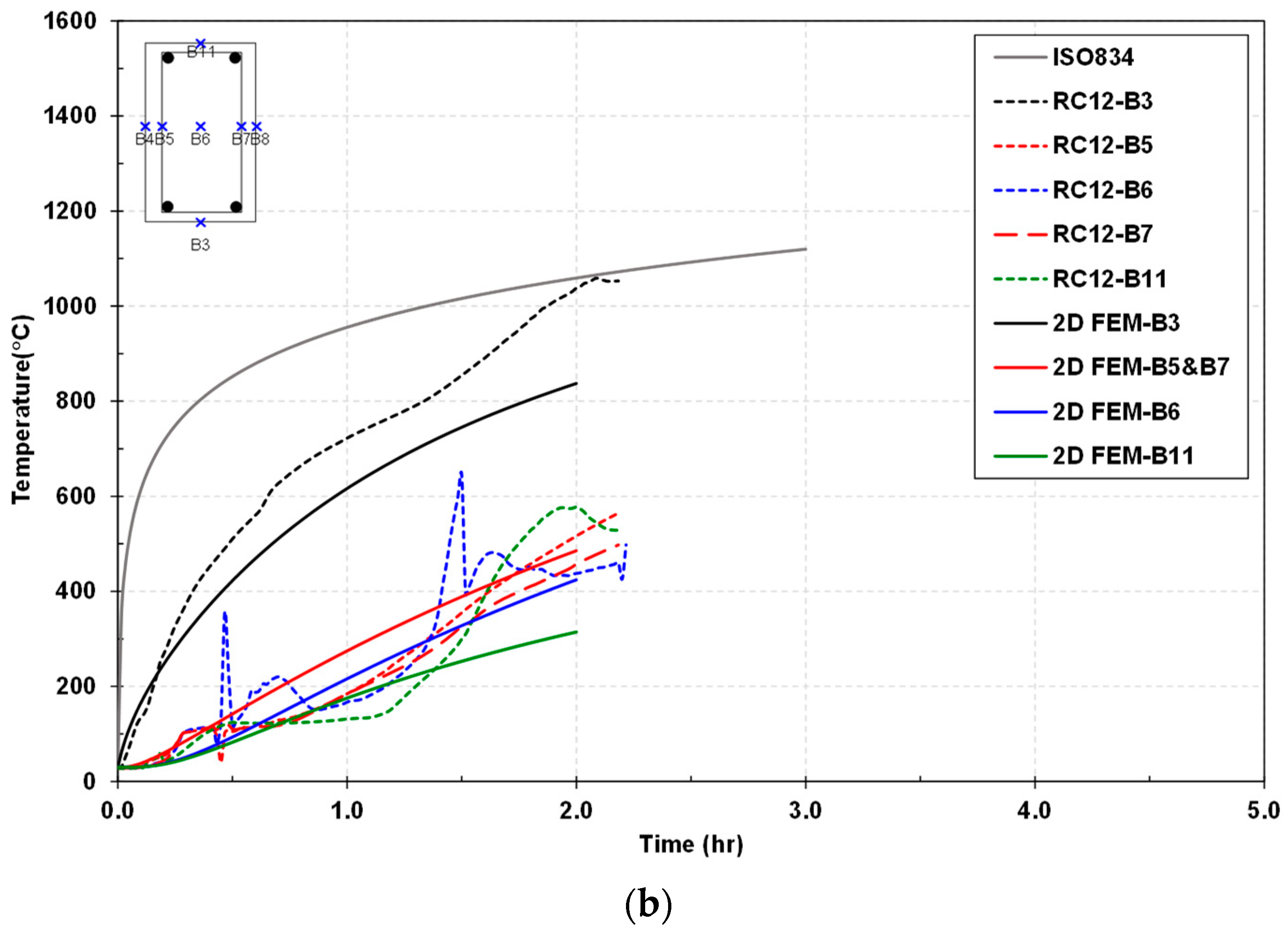
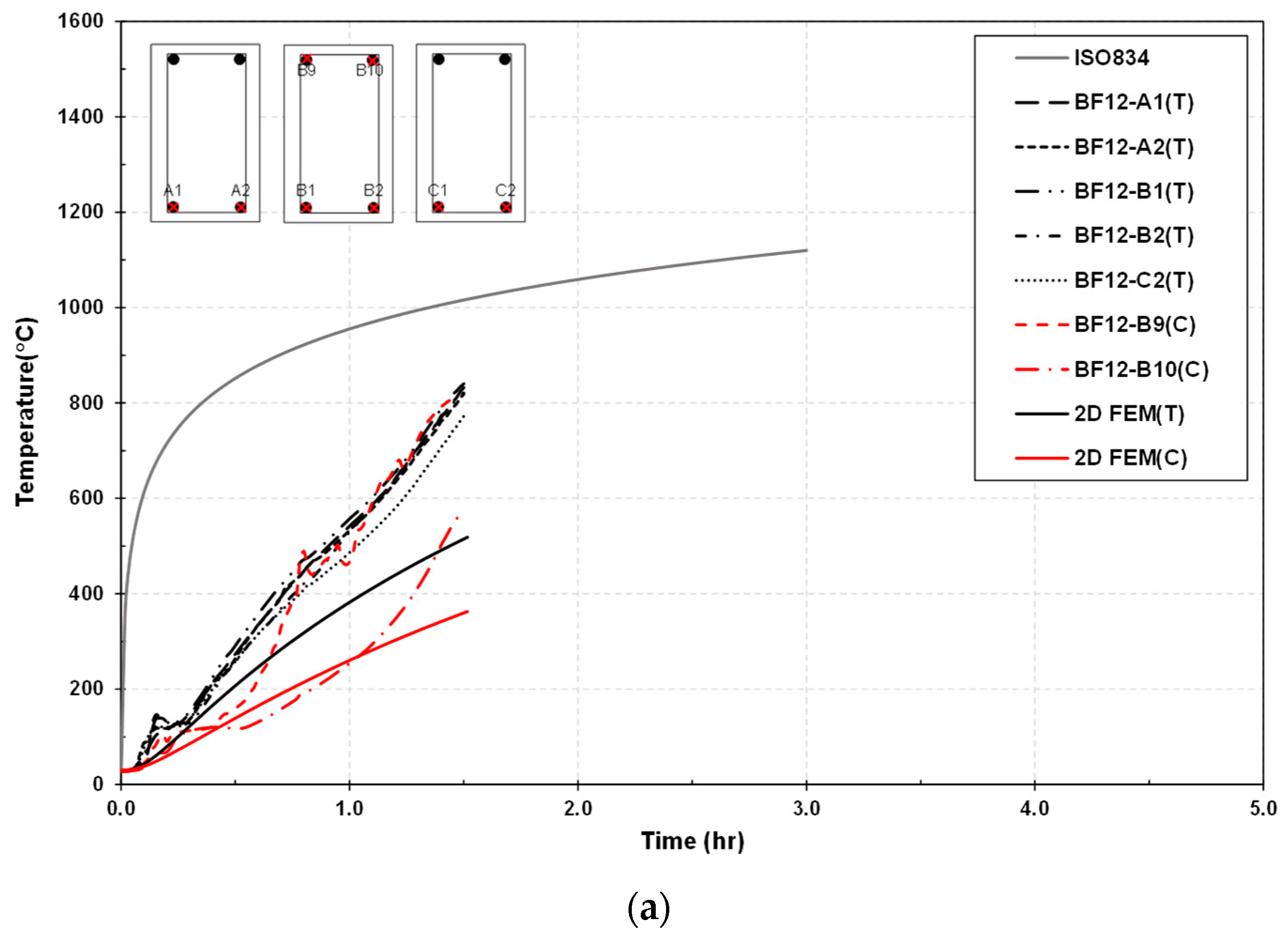
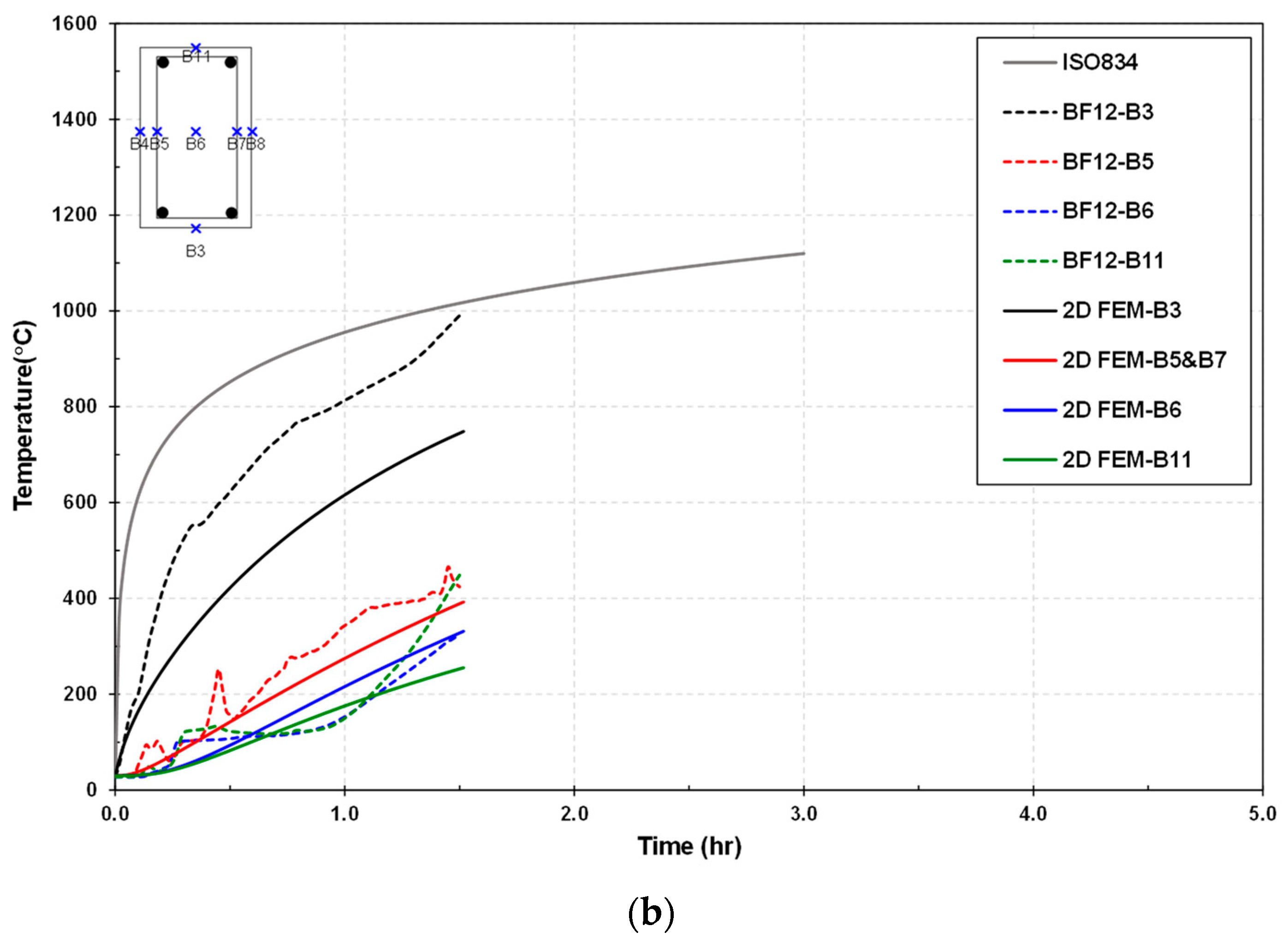
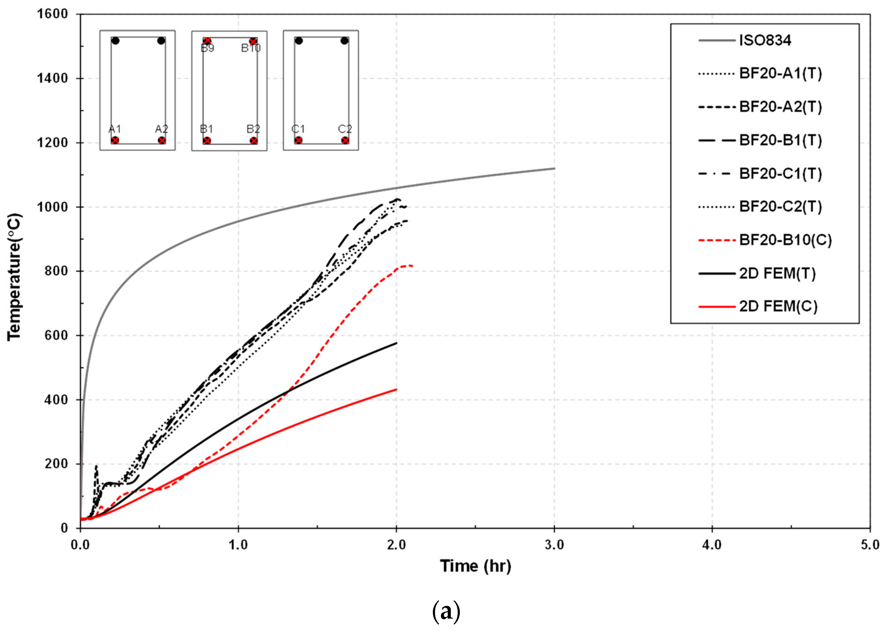
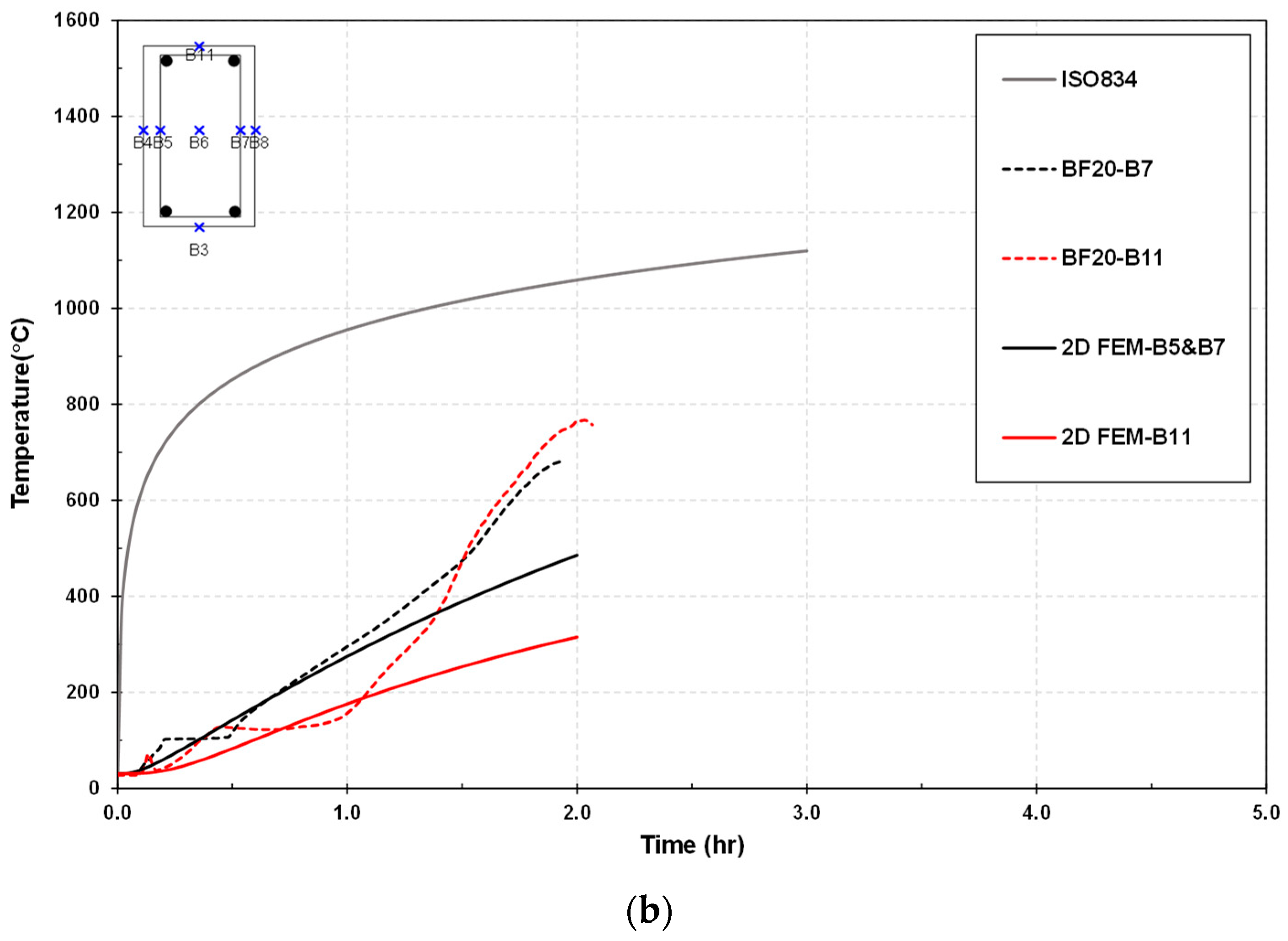
The comparison of the temperature versus time relationship between the tests and 2D FEM simulations is shown in Figure 14a,b, Figure 15a,b, and Figure 16a,b. Generally, the results indicate that the 2D FE analysis can predict the temperature development of the components in the beams along the time axis. However, the discrepancy between the test curves and numerical curves remains, due to the assumption of the 2D model for temporal transfer. In addition, the FEM prediction has a lower temperature distribution inside the cross-section than the temperature distribution obtained from the tests. This is because the prediction did not consider the effect of the cracks during the temperature heating.
In Figure 14a, Figure 15a, and Figure 16a, both experimental and numerical results indicate that the temperature duration at the bottom reinforcement was larger than that at the top reinforcement due to the heat transfer scheme. As can be seen in Figure 14, Figure 15, and Figure 16, similar to the experimental observation, the FE analysis demonstrates that the concrete soffit had higher temperature distribution than the steel reinforcement. Furthermore, the 2D FEM simulation is suitable to assess the temperature distributed in concrete rather than to predict the temperature distribution in the reinforcement. Conversely, the temperature measurements at different longitudinal sections of the beams were different because of the crack effect. This phenomenon could not be predicted by the 2D FEM. Therefore, in future works, the 3D FEM simulation is recommended to reflect the actual behavior of the test beams.

4. Conclusions

This study provides a valuable contribution to the state of the art by presenting new findings related to GFRP-RC beams exposed to fire. To explore the new findings, the concrete beams reinforced with steel or GFRP bars subjected to fire exposure were experimentally and numerically investigated against the standard ISO 834 fire curve. The thermal behavior of the test beams was examined, while the 2D FEM was used to predict the temperature distributions on the beam sections. The main new findings obtained from the present study can be summarized, as follows:
  • The temperature in the bending parts of the steel-RC beam was lower than that of the GFRP-RC beam. The average fire resistance rates of the steel-RC beam and the GFRP-RC beam were 83 min and 33–36.4 min, respectively. The critical temperatures measured at the steel rebar and at the GFRP rods were 593 °C and 300–330 °C, respectively. This means that the steel-RC beam had greater fire resistance than the GFRP-RC beam, and all beams failed due to the fire exposure less than the resistance time of 2 h.
  • The fire resistance of the beam reinforced with GFRP bars of 20 mm diameter (BF20) was better than that of the beam reinforced with GFRP bars of 12 mm diameter (BF12). The fire durations of the beams BF12 and BF20 were similar with the range of 31.8–46.4 min. It was found that the increase of the GFRP bar diameter for reinforcing the beams slightly enhanced fire resistance.
  • The deflection of the GFRP-RC beams was larger than that of the steel-RC beam due to the small elastic modulus of GFRP bars. The FEM simulation is an effective package for modeling the beams reinforced with GFRP and steel bars under the fire condition. The numerical prediction had a lower temperature distribution inside the cross-sections of the beams than that of the experimental measurements.

Author Contributions

Conceptualization, C.T., N.P (Natthanuch Poonpan) and S.K.; methodology, C.T., L.V.H.B., and N.P. (Natcha Phudtisarigorn); validation, N.P. (Natthanuch Poonpan) and N.P. (Natcha Phudtisarigorn); formal analysis, C.T., N.P. (Natthanuch Poonpan). and N.P. (Natcha Phudtisarigorn); investigation, C.T. and L.V.H.B.; resources, P.T.N. and S.M.; data curation, P.T.N. and S.M.; writing—original draft preparation, N.P. (Natthanuch Poonpan). and N.P. (Natcha Phudtisarigorn); writing—review and editing, C.T. and L.V.H.B.; visualization, C.T. and L.V.H.B.; supervision, P.T.N. and S.K.; project administration, C.T. and L.V.H.B.; funding acquisition, C.T., L.V.H.B., P.T.N., S.K. and S.M. All authors have read and agreed to the published version of the manuscript.

Funding

This research received no external funding.

Institutional Review Board Statement

Not applicable.

Informed Consent Statement

Not applicable.

Data Availability Statement

Not applicable.

Acknowledgments

This study was supported by Thammasat University Research Fund, Contract No. TUFT 51/2564. This research was also supported by Thammasat University Research Unit in Structural and Foundation Engineering, Thammasat University and by the Thailand Science Research and Innovation Fundamental Fund fiscal year 2023.

Conflicts of Interest

The authors declare no conflict of interest.

References

  1. Alsayed, S.; Al-Salloum, Y.; Almusallam, T.; El-Gamal, S.; Aqel, M. Performance of glass fiber reinforced polymer bars under elevated temperatures. Compos. Part B Eng. 2012, 43, 2265–2271. [Google Scholar] [CrossRef]
  2. Aslam, M.; Shafigh, P.; Jumaat, M.Z.; Shah, S.N.R. Strengthening of RC beams using prestressed fiber reinforced polymers–A review. Constr. Build. Mater. 2015, 82, 235–256. [Google Scholar] [CrossRef]
  3. Protchenko, K.; Szmigiera, E. Post-fire characteristics of concrete beams reinforced with hybrid FRP bars. Materials 2020, 13, 1248. [Google Scholar] [CrossRef] [PubMed] [Green Version]
  4. Qureshi, J. Fibre-Reinforced Polymer (FRP) in Civil Engineering; IntechOpen: London, UK, 2022. [Google Scholar]
  5. Sirimontree, S.; Keawsawasvong, S.; Thongchom, C. Flexural Behavior of Concrete Beam Reinforced with GFRP Bars Compared to Concrete Beam Reinforced with Conventional Steel Reinforcements. J. Appl. Sci. Eng. 2021, 24, 883–890. [Google Scholar]
  6. Al-Thairy, H.; Al-hasnawi, N.H. Behavior and Failure Mode of GFRP bars RC Beams under Elevated Temperature. In IOP Conference Series: Materials Science and Engineering; IOP Publishing: Bristol, UK, 2020; Volume 888, p. 012012. [Google Scholar]
  7. Maranan, G.B.; Manalo, A.C.; Karunasena, W.; Benmokrane, B.; Lutze, D. Flexural behaviour of glass fibre reinforced polymer (GFRP) bars subjected to elevated temperature. In Proceedings of the 23rd Australasian Conference on the Mechanics of Structures and Materials (ACMSM23), Byron Bay, Australia, 9–12 December 2014; Southern Cross University: Lismore, Australia, 2014; Volume 1, pp. 187–192. [Google Scholar]
  8. Wang, Y.C.; Wong, P.M.H.; Kodur, V.K.R. Mechanical properties of fiber reinforced polymer reinforcing bars at elevated temperatures. In Proceedings of the ASCE—SFPE Specialty Conference on Designing Structures for Fire, Baltimore, Maryland, USA, 30 September–1 October 2003; pp. 183–192. [Google Scholar]
  9. Bazli, M.; Zhao, X.L.; Bai, Y.; Raman, R.S.; Al-Saadi, S. Bond-slip behaviour between FRP tubes and seawater sea sand concrete. Eng. Struct. 2019, 197, 109421. [Google Scholar] [CrossRef]
  10. Chan, Y.W.S.; Zhou, Z. Advances of FRP-based smart components and structures. Pac. Sci. Rev. 2014, 16, 1–7. [Google Scholar] [CrossRef] [Green Version]
  11. Chitsazan, I.; Kobraei, M.; Jumaat, M.Z.; Shafigh, P. An experimental study on the flexural behaviour of FRP RC bemas and comparison of the ultimate moment capacity with ACI. J. Civ. Eng. Constr. Technol. 2010, 1, 27–42. [Google Scholar]
  12. Au, F.T.; Du, J.S. Deformability of concrete beams with unbonded FRP tendons. Eng. Struct. 2008, 30, 3764–3770. [Google Scholar] [CrossRef]
  13. Masmoudi, A.; Ouezdou, M.B.; Haddar, M. Mode of failure for reinforced concrete beams with GFRP bars. J. Theor. Appl. Mech. 2016, 54, 1137–1146. [Google Scholar] [CrossRef]
  14. Jongvivatsakul, P.; Thongchom, C.; Mathuros, A.; Prasertsri, T.; Adamu, M.; Orasutthikul, S.; Charainpanitkul, T. Enhancing bonding behavior between carbon fiber-reinforced polymer plates and concrete using carbon nanotube reinforced epoxy composites. Case Stud. Constr. Mater. 2022, 17, e01407. [Google Scholar] [CrossRef]
  15. Lenwari, A.; Soysak, S.; Thongchom, C. Torsional Behavior of Reinforced Concrete Members Wrapped with CFRP Sheets. In International Conference on Fibre-Reinforced Polymer (FRP) Composites in Civil Engineering; Springer: Cham, Switzerland, 2021; pp. 1566–1576. [Google Scholar]
  16. Lenwari, A.; Thongchom, C.; Aboutaha, R.S. Cyclic flexural performance of fire-damaged reinforced concrete beams strengthened with carbon fiber-reinforced polymer plates. ACI Struct. J. 2020, 117, 133–146. [Google Scholar]
  17. Thongchom, C.; Lenwari, A.; Aboutaha, R.S. Bond properties between carbon fibre-reinforced polymer plate and fire-damaged concrete. Int. J. Adhes. Adhes. 2020, 97, 102485. [Google Scholar] [CrossRef]
  18. Rathnayake, R.M.D.I.M.; Sridarran, P.; Abeynayake, M.D.T.E. Factors contributing to building fire incidents: A review. In Proceedings of the International Conference on Industrial Engineering and Operations Management, Dubai, United Arab Emirates, 10–12 March 2020; pp. 123–134. [Google Scholar]
  19. Zhang, X.; Qing-Qing, S.H.E.N.; Zhong-Yi, L.I.; Song-Hua, T.A.N.G.; Ying-She, L.U.O. Experimental study on fire resistance of reinforced concrete frame structure. In Proceedings of the 2014 International Conference on Mechanics and Civil Engineering (icmce-14), Wuhan, China, 13–14 December 2014; Atlantis Press; Zhengzhou, China, 2014; pp. 1031–1037. [Google Scholar]
  20. Phan, L.T. High-strength concrete at high temperature-an overview. In Proceedings of the 6th International Symposiumon Utilization of High Strength/High Performance Concrete, Leipzig, Germany, 6 June 2002; pp. 501–518. [Google Scholar]
  21. Toumi, B.; Resheidat, M. Influence of high temperatures on surface cracking of concrete studied by image scanning technique. Jordan J. Civ. Eng. 2010, 4, 155–163. [Google Scholar]
  22. Kodur, V.; Kumar, P.; Rafi, M.M. Fire hazard in buildings: Review, assessment and strategies for improving fire safety. PSU Res. Rev. 2019, 4, 1–23. [Google Scholar] [CrossRef]
  23. Rafi, M.M.; Nadjai, A.; Ali, F. Fire resistance of carbon FRP reinforced-concrete beams. Mag. Concr. Res. 2007, 59, 245–255. [Google Scholar] [CrossRef]
  24. Sadek, A.W.; El-Hawary, M.M.; El-Deeb, A.S. Fire resistance testing of concrete beams reinforced by GFRP rebars. J. Appl. Fire Sci. 2006, 14, 91. [Google Scholar] [CrossRef]
  25. Wang, Y.C.; Kodur, V. Variation of strength and stiffness of fibre reinforced polymer reinforcing bars with temperature. Cem. Concr. Compos. 2005, 27, 864–874. [Google Scholar] [CrossRef]
  26. Thongchom, C.; Lenwari, A.; Aboutaha, R.S. Effect of Sustained Service Loading on Post-Fire Flexural Response of Reinforced Concrete T-Beams. ACI Struct. J. 2019, 116, 593. [Google Scholar] [CrossRef]
  27. Yu, B.; Kodur, V. Effect of temperature on strength and stiffness properties of near-surface mounted FRP reinforcement. Compos. Part B Eng. 2014, 58, 510–517. [Google Scholar] [CrossRef]
  28. ASTM C39/C39M-16b; Standard Test Method for Compressive Strength of Cylindrical Concrete Specimens. American Society for Testing and Materials (ASTM): West Conshohocken, PA, USA, 2016.
  29. ASTM A370; Standard Test Methods and Definitions for Mechanical Testing of Steel Products. American Society for Testing and Materials (ASTM): West Conshohocken, PA, USA, 2022.
  30. ASTM D7205/D7205M; Standard Test Method for Tensile Properties of Fiber Reinforced Polymer Matrix Composite Bars. American Society for Testing and Materials (ASTM): West Conshohocken, PA, USA, 2021.
  31. (TISI) 20-2559; Steel Bars for Reinforced Concrete: Round Bars. Thai Industrial Standards Institute: Bangkok, Thailand, 2016.
  32. (TISI) 24-2559; Steel Bars for Reinforced Concrete: Deformed Bars. Thai Industrial Standards Institute: Bangkok, Thailand, 2016.
  33. ISO 834-1; Fire Resistance Tests—Elements of Building Construc tion. Part 1: General Requirement. International Standards Organization: Geneva, Switzerland, 1999.
  34. ASTM Test Method E119-08a; Standard Methods of Fire Test of Building Construction and Materials. American Society of Testing Materials: West Conshohocken, PA, USA, 2008.
  35. Hajiloo, H.; Green, M.F.; Noël, M.; Bénichou, N.; Sultan, M. Fire tests on full-scale FRP reinforced concrete slabs. Compos. Struct. 2017, 179, 705–719. [Google Scholar] [CrossRef]
  36. Bazli, M.; Abolfazli, M. Mechanical Properties of Fibre Reinforced Polymers under Elevated Temperatures: An Overview. Polymers 2020, 12, 2600. [Google Scholar] [CrossRef]
  37. Henkensiefken, R.; Briatka, P.; Bentz, D.; Nantung, T.; Weiss, J. Plastic shrinkage cracking in internally cured mixtures made with pre-wetted lightweight aggregate. Concr. Int. 2010, 32, 49–54. [Google Scholar]
  38. Krivenko, P.V.; Guzii, S.G.; Bodnarova, L.; Valek, J.; Hela, R.; Zach, J. Effect of thickness of the intumescent alkali aluminosilicate coating on temperature distribution in reinforced concrete. J. Build. Eng. 2016, 8, 14–19. [Google Scholar] [CrossRef]
  39. ANSYS. ANSYS User’s Manual; ANSYS, Inc.: Canonsburg, PA, USA, 2014. [Google Scholar]
  40. Lie, T.T.; Erwin, R.J. Method to calculate the fire resistance of reinforced concrete columns with rectangular cross section. ACI Struct. J. 1993, 9, 52–60. [Google Scholar]
  41. EN 1992-1-2; Deign of Concrete Structures. Eurocode 2, Part 1–2: General rules—Structural fire design. European Committee for Standardization: Brussels, Belgium, 2004.
  42. Kodur, V.K.R.; Dwaikat, B. A numerical model for predicting the fire resistance of reinforced concrete beams. Cem. Concr. Compos. 2008, 30, 431–443. [Google Scholar] [CrossRef]
  43. Kodur, V.K.R.; Dwaikat, M.B.; Fike, R.S. An approach for evaluating the residual strength of fire-exposed RC beams. Mag. Concr. Res. 2010, 62, 479–488. [Google Scholar] [CrossRef]
  44. Gao, W.Y.; Dai, J.G.; Teng, J.G.; Chen, G.M. Finite element modeling of reinforced concrete beams exposed to fire. Eng. Struct. 2013, 52, 488–501. [Google Scholar] [CrossRef] [Green Version]
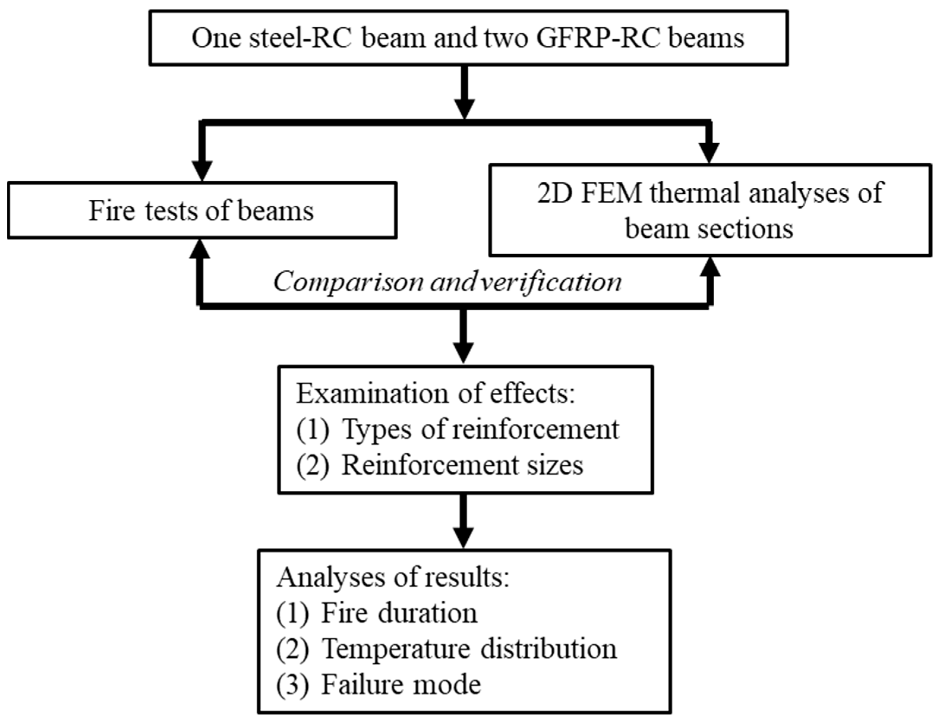
Figure 1. Flowchart of the research program.
Buildings 13 00609 g001
Figure 2. Beam details. (a) Beam RC12; (b) Beam BF12; (c) Beam BF20.
Buildings 13 00609 g002aBuildings 13 00609 g002b
Figure 3. LVDT and thermocouple installation location of the sample beam.
Buildings 13 00609 g003
Figure 4. Fire furnace (unit: millimeter); (a) front view; (b) top view; (c) side view.
Buildings 13 00609 g004
Figure 5. Fire test furnace; (a) front view; (b) top view; (c) side view.
Buildings 13 00609 g005
Figure 6. Fire test setup.
Buildings 13 00609 g006
Figure 7. Temperature versus time relationship in the beam RC12. (a) Reinforcement; (b) concrete.
Buildings 13 00609 g007
Figure 8. Temperature versus time relationship in the beam RF12. (a) Reinforcement; (b) concrete.
Buildings 13 00609 g008
Figure 9. Temperature versus time relationship in the beam RF20. (a) Reinforcement; (b) Concrete.
Buildings 13 00609 g009
Figure 10. Comparisons in the temperature: (a) RC12 and BF12; (b) BF12 and BF20.
Buildings 13 00609 g010
Figure 11. Failure of beams subject to fire.
Buildings 13 00609 g011
Figure 12. Characteristics of the PLANE55 element.
Buildings 13 00609 g012
Figure 13. Concrete beam, 2D (units in millimeters).
Buildings 13 00609 g013
Figure 14. Comparison between prediction and testing of RC12 beams. (a) Reinforcements; (b) concrete.
Buildings 13 00609 g014aBuildings 13 00609 g014b
Figure 15. Comparison between prediction and test of the BF12 beam. (a) Reinforcements; (b) concrete.
Buildings 13 00609 g015aBuildings 13 00609 g015b
Figure 16. Comparison between prediction and test of the BF20 beam. (a) Reinforcements; (b) concrete.
Buildings 13 00609 g016aBuildings 13 00609 g016b
Table 1. Details of test beams.
Beam No.Tension ReinforcementCompressive Reinforcement
RC122DB122DB12
BF122GFRP122GFRP12
BF202GFRP202GFRP12
Table 2. Mechanical properties of materials.
MaterialsYield Strength
(MPa)
Ultimate Strength
(MPa)
Elastic Modulus
(GPa)
DB12466540210
RB9270410206
GFRP12-85145
GFRP20-93545
Table 3. Chemical composition of steel (TIS, 2016).
Steel TypeChemical Composition % (Max)
CarbonManganesePhosphorusSulphurCarbon+
Manganese/6
RB90.28-0.0600.060-
DB20-1.850.0600.0600.500
Table 4. Critical temperature of reinforcing steel and GFRP rods of sample beams.
TC PositionRC12
(minutes)
(Tcr = 593 °C)
BF12
(minutes)
(Tcr = 300–330 °C)
BF20
(minutes)
(Tcr = 300–330 °C)
A1-33–3629–33
A28033–3633–37
B19031–3432–35
B29134–38-
C171-30–34
C2-34–3835–39
Disclaimer/Publisher’s Note: The statements, opinions and data contained in all publications are solely those of the individual author(s) and contributor(s) and not of MDPI and/or the editor(s). MDPI and/or the editor(s) disclaim responsibility for any injury to people or property resulting from any ideas, methods, instructions or products referred to in the content.