Abstract
Modeling the meso-scale behavior of a material allows one to answer many problems in an inductive reasoning approach. By simulating the behavior of the sample, researchers can correct the overall behavior of the material. The purpose of this article was to gather the main information linking the issue of tomographic imaging to the modeling of damage mechanisms. This paper addresses the topic of meso-scale modeling of cementitious materials. The authors have mapped the interconnectedness of the issues of cementitious materials and X-ray computed tomography (µCT) according to the Web of Science database. The main interconnecting threads are indicated. The authors focused on the use of µCT. The theoretical basis for conducting tomographic measurements is presented. Reference was made to the basics of physics and mathematics in X-ray projection and data reconstruction. Tools and analyses for data processing are indicated. The benefits of in situ µCT are indicated with reference to the practical application of the method. In addition, the main developments of recent years in the most widely used computational methods for meso-scale models are presented.
1. Introduction
Cementitious materials are heterogeneous, cohesive-frictional materials and exhibit complex non-linear inelastic behavior under multiaxial stress states. Concrete is one of the most common materials, which influences the need for analyses of not only strength [1,2,3], but also experimental [4,5,6], environmental [7,8,9] or thermal [10,11,12] properties. Despite rising costs and the search for new technological solutions [13], interest in cementitious materials as a construction material is not waning. Figure 1a shows the number of articles published on the topic of cementitious materials in the period from January 1990 to November 2022. The data were obtained from the Web of Science database. A dynamic upward trend in research interest is evident. In the last five years alone, more than 10,000 papers have been written on the topic of cementitious materials. Research interest is not declining, and with the development of modern research technologies and techniques, papers are presenting more practical results to push science ahead.
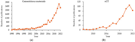
Figure 1.
Graphs of published papers over time based on the Web of Science catalog (a) cementitious materials; (b) xCT (X-ray computed tomography) in the categories materials science multidisciplinary, engineering manufacturing, civil engineering and construction building technology.
In parallel, advanced testing methods are developing that allow for the description of the internal structure of the material under examination in a non-destructive manner. X-ray computed tomography (µCT, xCT) is a non-invasive imaging technique that has gained popularity in the field of research on cementitious materials. CT scans allow for the creation of three-dimensional images of the internal structure of a material, providing valuable information about its microstructure, porosity and segmentation. This information is critical for understanding the behavior and performance of cement-based materials, such as concrete, and for evaluating factors that affect their durability. For example, CT scans can provide insight into the pore structure of concrete and track the movement of water and air through the material, which can have a significant impact on its overall strength and durability. In addition to its use in the research of cement-based materials, X-ray CT is also used in construction and engineering to assess the quality of concrete and other cement-based materials. CT scans can detect early signs of cracking, deterioration, and other damage after the sample is loaded. This allows one to detect the effects, introduce countermeasures and prevent further damage. This information can also be used to develop new and more durable materials and construction methods. X-ray CT is also useful in the study of cement-based composites, as it allows for a detailed analysis of the behavior and performance of these materials under various loads. Typically, µCT does not leave a mark on the sample, although in the case of electronics, damage or loss of data can occur. The paper [14] widely referes to tomographic studies on cementitious materials. CT imaging provides quantitative information on pores morphology, but unlike microscopy, it gives 3D information [15]. The accuracy of the acquired µCT data makes it highly suitable for the development of meso-scale models. Due to the high cost of the device, xCT is not available in every research facility. Figure 1b shows a graph of articles published on xCT in recent years. It should be noted that the data do not include items related to medicine. The data refer to publications in the Web of Science catalog in categories directly related to construction: materials science multidisciplinary, engineering manufacturing, engineering civil and construction building technology. As with the material itself, xCT technology is of increasing interest. In the last five years, more than 380 articles have been added to the Web of Science catalog on research using CT in materials science.
Generated models based on µCT can be entered into numerical software. The history of numerical calculation in civil engineering dates back to the 1940s, when engineers began using electronic computers to solve complex structural analysis problems. The early methods were limited to solving linear problems, but with advances in computer technology and mathematical techniques, engineers were able to tackle non-linear problems as well. This led to the development of the finite element method (FEM) in the 1960s; FEM became a standard tool for structural analysis and design in civil engineering. The finite element method is a numerical method that allows engineers to analyze and design complex structures. It divides a structure into small elements, representing them mathematically, and solves equations to determine their behavior under different loading conditions. This method has become a staple in modern civil engineering, enabling engineers to optimize designs for safety, cost and sustainability.
In contrast to FEM stands the discrete element method (DEM). DEM is a numerical technique for simulating the behavior of granular materials, such as soil, rock, concrete and debris. It is based on the principle of modeling individual particles and their interactions, rather than treating the material as a continuous mass. This method has become an important tool for civil engineers to analyze and design certain structures, such as retaining walls, slopes and embankments, where the behavior of granular materials is critical. Unlike FEM, which focuses on the behavior of the structure as a whole, DEM provides a more detailed understanding of the behavior of individual particles and their interactions, making it likely to be extremely useful for meso-scale applications.
Figure 2 shows a linkage map of the issues of cementitious materials raised in articles from the last five years, based on the Web of Science catalog. Visually, four main threads can be distinguished, which can be reduced to three main trends when the content is analyzed. Researchers describe their work in terms of the material used and the research strand (red group), where attention can be drawn to the cementitious composite itself, types of concrete, additives such as fiber and issues (failure, load, uniaxial tests). The second group (light green) includes phenomena and properties such as cracking, self-healing and simulation. The third group comprises entries in the dark green and blue groups. Here, one can distinguish issues concerning bonds, chemical reactions and environmental issues—including ecological aspects (waste placement in the material). In the context of this issue, attention can be drawn to “failure mode”, directly related to “crack”, “model”, “reinforcement” or “load”.
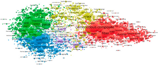
Figure 2.
Map of related topics—cementitious materials.
A similar linkage map is shown in Figure 3. The subject of the analysis was CT in the categories materials science multidisciplinary, engineering manufacturing, civil engineering or construction building technology. ‘Concrete’ was mainly linked to ‘microstructure’, ‘model’, ‘pore structure’, ‘evaluation’ and ‘volume’. The main trends in cementitious materials research not only indicate the use of tomographic studies from evaluation but also indicate the search for the use of microstructure or pore network data to define models.
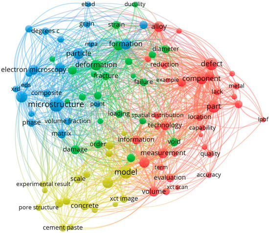
Figure 3.
Map of related topics—xCT.
In reviewing the available literature, the authors did not see any papers referring to the use of µCT to develop a path to model the behavior of a sample with numerical software. The aim of this paper is to bring together crucial information about µCT and the conduct of numerical calculations. The authors seek to identify possible directions for the integration of data acquired by µCT scanning together with analysis and testing equipment. Specialized equipment can be used to carry out investigations that best reflect the behavior of cementitious materials with respect to their microstructure.
2. µCT Basics
X-ray tomographs as used in industry rely on X-ray spectroscopy. A complete description is provided in a paper [16] published more than 20 years ago. It still correctly describes the principles of operation. The sample is tested in a special chamber of the device. The sample is positioned between a radiation emitter and the detector. The test is characterized by the position of the sample in the chamber, the radiation power used and the detector operating parameters. Proper selection of the required parameters makes it possible to receive results enabling further 3D reconstruction of the object. Unlike medical tomography (where the patient’s position must be stable), during an industrial scan, the detector and tube remain in a fixed position, while the object under examination is rotated along a vertical axis. Thousands of measurements of the attenuation of the beam of radiation passing through the object under examination are taken during a single scan.
An X-ray tube (commonly called a tube) is an X-ray emitter. In the vacuum tube, electrons are emitted from the heated filament. The electrons are accelerated toward the anode by the potential difference UACC. The electrons pass through a hole in the anode to a magnetic coil, which concentrates the electrons over an area of a few µm on the target. The target is covered by a thin layer of tungsten on a diamond. At the target, electrons are abruptly slowed down, resulting in the generation of an X-ray beam. The energy of the electrons is converted 99% into heat, 1% is converted into X-rays [17].
A sample is placed between the radiation emitter and the detector. The sample is mounted on a high-precision manipulator. By convention, the manipulator moves in three perpendicular directions and allows rotation in the vertical axis. The x-ray tube–sample–detector distance affects the magnification of the sample. A sample positioned closer to the tube will give a higher magnification than one positioned next to the detector, affecting the voxel size (vx) measurement accuracy. The voxel size is the size of the cubes from which the whole scan is constructed. The voxel is associated with a gray value and has a size of . The authors [18] pointed out that specifying the required resolution of a µCT image of particles depends on the targeted measurement task. The experimentally adopted ratio of particle size to voxel size should be greater than 10. However, when transferring these results to other measurement tasks, it is also necessary to take into account the variability in the measurement of the µCT system used and the specific shapes, textures and mineral composition of the studied particles. In [19], the problem of selecting the appropriate resolution and the influence of the voxel size on the results is described. It is necessary to emphasize the important distinction between the resolution of physical objects and the size of pixels (voxels). The scale of object resolution length corresponds to the smallest characteristic that can be resolved in an image and varies with the size of the sample and the internal attenuation contrast of the material in relation to the background. Pixel (voxel) size is the element size of the information in the image.
The shadow of the X-rays is converted into visible light through the scintillation screen, and the visible light is converted into the digital image by the optical sensor. The main advantage of this approach to the detection problem is to obtain a high-contrast image without distortion. Detailed information on the detectors is available in publications [20,21]. ISO 15708 part 1 splits X-ray detectors into two groups: ionization detectors and scintillation detectors. The second common division of modern xCT detectors is a line detector and a flat panel detector. The interior of the tomography chamber equipped with a flat panel detector is shown in Figure 4a.
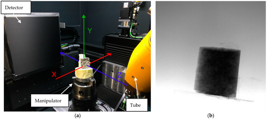
Figure 4.
CT scans (a) interior of the CT chamber; (b) single projection. Source: own materials.
2.1. Absorption of X-rays
For details of the technology and background on the principles of physics, see the [22,23,24]. The theoretical basis of X-ray computed tomography is based on the Beer-Lambert law. A monochromatic radiation beam I0 after passing through a homogeneous absorbing medium of thickness l is weakened according to Equation (1):
The number k is the linear attenuation coefficient. Its value is material-specific and depends on the density, atomic number, contribution for photoelectric attenuation, incoherent Compton scattering and coherent Rayleigh scattering. Equation (1) can be developed to the form shown by Equation (2).
In the above equation refers to the linear attenuation coefficient at a point (x, y, z) in the local sense. The length s is the length of the path measured along the ray. X-ray radiation has its direction described by a vector . The integral is determined between the entry point of the radiation into the sample , and the exit at a distance of .
2.2. Principles and Assumptions in Industrial µCT Scanners
As for further considerations, the assumption of the absence of imperfections in the arrangement of the device generating the projections must be made. It is also assumed that the radiation falls perpendicular to the detector plane and that sample rotation occurs in the vertical axis. According to the standard axes in tomographs (e.g., GE phoenix M), the radiation propagates in the direction of the , direction is the vertical axis (around which rotation takes place) and is the horizontal axis parallel to the detector plane. The axes are drawn in Figure 4a. A single pixel of the (x, y) detector will receive a signal I (x, y) of power according to the Beer-Lambert law:
Author [22] also indicates the practical application of the projection of the sample’s X-ray attenuation field, which is defined as below.
Value can be defined as the difference . In addition, the rotation of the sample in the vertical axis by a given angle θ is taken into account. Assuming the system ( on the device’s manipulator, it is given:
Making the final transition from the local system to (X, Y, Z) the projection P (x, z, θ) with angle θ is described by Equation (6).
Obtaining k (X, Y, Z) from the set of projections P (x, y, θ) is an inverse problem. In practice, this process is called reconstruction. After the reconstruction process based on a set of 2D projections, the device operator receives a set of 3D data allowing inspection of the material interior. A single projection is shown in Figure 4b.
2.3. Reconstruction
Once the projections giving information about the cross sections have been obtained, the algorithm proceeds to the logarithm. Projections are processed by inversion and calculation of the logarithm of the grey values performing . Then ramp filtering is carried out [25], which enhances edges or higher frequencies. To reconstruct the 3D image, the 2D projections are reprojected into a virtual sample volume. Subsequently, reconstruction takes place.
The reconstruction method called the reverse radon transform [26] is usually based on the Fourier transform. The formula is valid for the case where the source of the beams describes a bounded curve satisfying a set of weak conditions. A reduction in the dimension of the problem (from three to two) can be made by mapping the 3D space as a set of cross sections. A complex mathematical description was proposed in the 1980s [27] and has been developed over the years [28]. The method is based on the inverse Fourier transform of , the support of which is contained in the compact space Ω. We will denote the inner product of two vectors α, β ∈ R3 by <α, β>. We will denote the integral of the function over the domain D in R3 by . For the following formula, f is a real integrable function on R3.
In most cases, the radiation used has a polychromatic characteristic [29]. Most reconstruction methods cannot correctly check the non-linearity of the absorption of polychromatic X-rays [30]. As a result of beam hardening, the images may contain artifacts that significantly reduce the quality of the data. An extensive description of the problems associated with reconstruction is given in [22]. The author described the issues of geometric considerations, calibration, artifacts and software. Currently, the offered software has a built-in reconstruction module dedicated to data from a specific manufacturer’s device.
The second method of data reconstruction that is less commonly used is algebraic reconstruction techniques (ART) [31]. It has been developed into a simultaneous algebraic reconstruction technique. The basics of ART algorithms are simple and intuitive. Each measured (via absorbance) density is projected back through the reconstruction space in which densities are iteratively adjusted to bring each reconstructed projection into correspondence with the measured projection [32]. It is also worth mentioning the development of deep learning-based reconstruction methods [33,34,35,36]. These methods are still being developed and are far less common.
2.4. Use of Computed Tomography
The resolution obtained in modern µCT research is very well suited to the study of the structure of heterogeneous cementitious materials whose fine fractions are 100 µm (or more) in size [37]. Because of its accuracy and detail, µCT has applications in the study of precision materials used, for example, in aerospace [38]. Numerous publications point to the usefulness of µCT in the study of various types of cementitious materials. Looking at the material itself, several groups can be distinguished. Research on cement paste has been carried out in [39,40,41,42]. The authors [43] propose a method to quantify the degree of hydration of slag-blended cement paste with the application of µCT. Applications for µCT in plain concretes were found in publications [44,45], lightweight concretes [46,47], foamed concretes [48,49], high porosity concretes [47], magnesium oxychloride cement concrete [50] and reinforced concrete [51,52].
The µCT data were used to assess the compactness of the concrete [53]. The technique has also been used to characterize the surface of concretes [54]. Studies of the effect of static loading on concrete specimens using tomographic imaging are known [55]. The usefulness of the tomographic image method in the evaluation of shear tests is indicated in [56]. There are studies that show how to determine the change in pore inertness of a concrete sample subjected to freezing cycles by tomography using a medical device [57]. Basic tomographic studies of steel fiber-reinforced concretes are presented in the publication [58]. Tomographic analysis mainly focused on the arrangement of the fibers in volume and the cracks created during the strength tests. The effectiveness of neutron tomography is indicated for the analysis of samples with high moisture content. Neutrons are very strongly absorbed by water, making it possible to image the water distribution with high contrast. Another advantage is that neutrons have high penetrating power, making it possible to image large samples. The disadvantage is the complexity of such systems [59]. In [60], the effectiveness of neutron tomography in tracking water movement in samples of cementitious materials is indicated. The use of neutron tomography has been well demonstrated in [61]. The researchers conducted an analysis of cement-based materials for the conditioning of low- and intermediate-level radioactive waste. A large amount of water inside hardened cement samples deteriorates the quality of neutron radiographs due to a large number of incoherent scattering effects. There are also known applications of dual-energy X-ray computed tomography for the detection of voids in fiber-reinforced composites [62].
Porosity analyzes are often used when looking for defects in concrete [59,63] or changes in the material caused by external influences. Leading software that works with CT data allows automated porosity/inclusion analysis. Pointing out the usefulness of tomography, one should also mention the emerging trend of 3D printing of cementitious materials. Research [64] looks at the use of a halloysite nanotube as a mineral additive to enhance the properties of 3D printable geopolymer mortar. Authors used μCT imaging technology to examine both mold-cast and 3D-printed specimens to assess their internal structures. Tomography was utilized to visualize the material and measure the level of porosity. By analyzing the data, the study was able to compare the porosity of different samples, taking into account not only the overall porosity but also the number and size of pores. Another example of research that can be mentioned is described in [65]. The microstructure of 3DP-ECC was studied using µCT scanner. The pores’ features and distribution were captured and analyzed. The CT scans showed that the porosity within the layers and between the inter- and intra-layer did not have significant differences, and it was only possible to differentiate the layers based on their volumes with the help of CT scans.
Tomography is also used to indicate geometric changes resulting from external impacts. In [66] authors worked on a method to assess the wear of shaft guides with the application of nondestructive and semi-destructive testing methods. Among the tools used was µCT. The authors took samples of wooden guides and analyzed their wear under laboratory conditions. µCT allowed internal structural damage to be indicated and a nominal/actual analysis was carried out. Analysis was used to map the structure destruction of the guide surface. A broad overview of existing methods of working with CT-acquired data is given in the paper [53].
2.5. Dynamic CT and Damage Mechanisms of Cementitious Materials
Dynamic CT (4DCT, CT-4D) is a technique widely used in imaging during medical examinations [67,68,69]. Procedures have been developed to enable the tracking of changes in the tested object under the influence of an external phenomenon. It involves recording multiple images over time with the ability to play back the processes as video. In X-ray tomography, it is possible to obtain measurements of the specimen during external influence. In the context of analyzing the mechanism of damage, the behavior of the concrete structure during each loading stage is important. The crack formation process is shown in Figure 5. A natural phenomenon resulting from the difference in the properties of the aggregate and the matrix is the occurrence of tensile stresses. In the initial phases of loading, the formation of microcracks occurs. These microcracks generate bridging stresses as they move. When the tensile strength is exceeded, a decrease occurs as the load increases, and the friction between the concrete elements decreases due to the enlargement of the cracks. A detailed description of the phenomenon is presented in [70]. Due to the material characteristics, the available sources refer to specific mixtures. However, detailed descriptions affecting the possibility of 3D modeling of the damage mechanism of cementitious materials are still lacking.

Figure 5.
Development of cracks with increasing tensile stresses [71]. The letters in the chart indicate the limits of the zones.
Computed tomography has been used to assess the mechanism of damage [72]. Authors [72] highlighted that high-resolution computer tomography can be used to identify microstructures in composite materials in three dimensions, such as fiber distribution, particle volume fraction and damage mechanisms such as fiber cracks and breaks. There are devices such as the in situ loadcell tensile stage for X-ray CT applications [73]. It allows for static or thermal effects inside the tomography chamber. Due to their low popularity and high cost, there are still few publications indicating the use of such tests. The procedure involves a gradual increase in the forces acting on the sample. After an increment of force, the piston is stopped, and a 360° scan is performed. The measurement is followed by another force increase and another scan. Once the specimen is destroyed (or the set force is reached), the operator completes the test by pulling the entire loadcell with the sample out of the tomograph chamber. A scan performed in this form should be as short as possible to reduce the effects of relaxation [74]. There are known applications of the method for the assessment of damage of composite materials [75]. It has been found that a reduction in total porosity due to increased load can only be predicted by in situ CT measurements, which confirms the usefulness of the proposed tests. Examples of cross-sections obtained in the in situ compression test are shown in Figure 6.
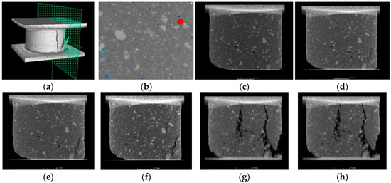
Figure 6.
Destroyed cementitious soil during tomographic examination: (a) cross-sectional location on 3D reconstructed specimen; (b) graphical result of porosity analysis (zoom) color scale indicates pore size, (c) sample inside Deben, unloaded condition, (d) sample inside Deben, piston displacement 0.12 mm, (e) sample inside Deben, piston displacement 0.18 mm, (f) sample inside Deben, piston displacement 0.24 mm, (g) sample inside Deben, piston displacement 0.48 mm, (h) sample inside Deben, piston displacement 0.54 mm. Source: own materials.
Authors [76] used X-ray µCT in situ loadcell to investigate the internal structure of a 3D-printed sample of alloy. In the paper, a tensile test was used. Measurements were carried out at six load levels. The authors used porosity analysis to quantify the changes that occur in the sample. According to the paper, the volume of this pore did not change significantly in the tensile process. In addition, the data obtained allows a visual assessment of the formation of the failure process, the determination of the angle of cracking in relation to the direction of force or the development of plastic deformation. Similar studies have been carried out for carbon fiber/epoxy composites [77], CFRP laminates [78], asphalts [79] and shales [80].
In situ X-ray studies on cement paste were carried out almost 10 years ago [81]. The researchers indicated the possibility of determining the deformation of the specimens under external loading. The sample was subjected to further load thresholds in a compression test inside the CT chamber. After reaching the stage, CT scan was performed. Researchers used the average gray scale values and standard deviations of the grayscale values as a measure of the change in the sample. Once the results of the proposed analysis are visualized, the change in sample structure is easily discernible, which will greatly facilitate the calibration of the numerical models. A similar research process was presented by the authors in [74]. The researchers subjected cement-based composites to strain-hardening tests. Tension and compression experiments were carried out on specially prepared miniature specimens in a testing rig integrated in an industrial computed microtomography. The paper raises several technically relevant issues. The duration of the scan should be as short as possible. This affects relaxation effects and measurement reliability. The duration of a single scan was approximately one hour, so the elongation (force) plots show significant drops at the time of scanning. A single voxel had a dimension of (13 µm)3. This resolution allowed the authors to detect microcracks. The authors further indicated the usefulness of 2D radiography as a primary tool for describing changes within a structure. Bending tests are also used to assess the damage of concrete [82]. Measurements of crack mouth opening displacement was performed in two steps. Beam was scanned under the existing residual force and the second one was scanned after beam unloading. The maximum width of the crack during continuous µCT scanning was approximately 20% to 30% higher than the beam being unloaded to the scanner. In situ studies to determine the differences in meso-scale damage evolution of concrete under static and dynamic tensile loading using µCT are presented in [83]. It has been confirmed that the failure mechanism is specific to the type of loading. The nature of the failure can be determined by evaluating the tomographic data.
3. Numerical Analysis
Concrete structures are becoming increasingly analyzed in detail using numerical software. Computed tomography allows the structure of the scanned element to be accurately represented on a meso-scale. The resulting geometry is the basis for further calculations. Numerical analysis is based on the solution of a set of equilibrium equations and kinematic admittance of the displacement field. The models are based on boundary and initial conditions, which are assumptions of the designer. The finite element method is one of the most popular and widespread computational methods used in construction, mechanics, fluid, air or heat flow simulations. In its basic form, it is based on Equation (8), where [M] is the mass matrix, [C] is the damping matrix, [K] is the stiffness matrix, [u] is the displacement matrix and [F] is the force matrix.
It is generally assumed that concrete is treated as an initially isotropic material with anisotropies caused by a change in stresses [84]. The combination of static and kinematic admittances is the essence of constitutive models. The material constitutive law usually arises as a result of complex experiments [85]. A complex review of the literature on constitutive models is presented in [86]. The publication highlights the main constitutive models and their division. The models were divided into linear and non-linear models. In addition, the general applicability of both groups is pointed out. Linear elastic models are the most basic type of constitutive models used to describe the behavior of concrete. In these models, concrete is treated as having linear elastic properties until it reaches its ultimate strength, at which point it fails in a brittle manner. For concrete under tension, the linear elastic model is accurate and sufficient in predicting behavior up to failure due to the low failure strength. However, concrete under multiaxial compressive stress exhibits nonlinear behavior and linear elastic models are not effective in these cases. Nonlinear constitutive models can provide better results and there are two main approaches used for nonlinear modeling: secant formulation (total stress-strain) and tangential stress-strain (incremental) formulation. There is still a need to find new models for special applications [87,88]. The correlation of constitutive relationships allows for a more accurate representation of the behavior of the simulated phenomenon. The most advanced models for complex concrete failure simulations are shown in Table 1.

Table 1.
Examples of complex constitutive models used for cementitious materials.
The numerical approach and X-ray CT technologies are widely used for simulations that have higher accuracy, but each numerical model should be created on the basis of a section and scanning of physical specimens, which is called experimental dependence [100]. Applications of reconstructed models and analyses to develop models of carbon fiber-reinforced textile composites are known [101,102]. Tomographic data can be represented with varying degrees of accuracy as grids fed into numerical environments generating similar behavior with real samples [45]. In addition, the development of methods to extract CAD models from µCT data makes it easier to work with scans of poor quality or full of artifacts [26]. Voronoi cells are also known to be used to describe a sample based on µCT scan data [103]. The 3D Voronoi diagram of the sample is created by using the Voronoi cells, which represent the aggregates and mortar in the meso-scale. The Voronoi algorithm generates a new synthetic dataset representing the sample based on statistics determined by measurements. The generation of 3D meso-scale models on the basis of µCT tests allows accurate simulations and calibration of numerical parameters with in situ experimental results. Studies linking experiments and numerical analyses to a given load set are summarized in Table 2.
Table 2.
Sources describing the type of effect.
Paper [37] refers to the application of models of concrete reinforced with polymer short fibers obtained by µCT to finite element calculations. The authors did not transfer the sample model into the numerical environment. The µCT data were used to quantify the pore distribution in the sample and to determine the geometry of the fibers. The statistical data obtained allowed for the determination of general material characteristics capable of addressing a wide range of applications. The analytical and numerical calculations are in good agreement, providing a maximum discrepancy of ~2.5%. The paper [126] refers to the study of the adhesion of steel fibers to concrete. The authors focused on an accurate representation of the fiber geometry in order to perform specimen-specific numerical calculations. The research indicated a high correlation between the change in porosity (appearance of defects) in the matrix and the occurrence of boundary stresses in the FEM calculations. The graphs, together with the FEM solution, are shown in Figure 7. In the study [127], micro-CT was employed to obtain the non-randomly oriented distribution of ellipsoidal pores in cement paste with an AE-agent added. The authors proved that µCT provides accurate data about non-randomly oriented pores, and thereby aids in the utilization of the numerical and Mori–Tanaka method. In [128], the authors presented a method to accurately generate a 3D mesh based on µCT gray value. This study proposes a FEM model to investigate the deterioration of concrete subjected to multiple physical forces, based on its 3D microstructure obtained through X-ray CT imaging. The CT images are converted into a mathematical matrix and transformed into 3D voxels with varying gray values, which serve as the basis for the FEM analysis. A threshold value of 200 is set to separate the mortar and aggregate components in concrete. The generated data were used for mechanical, thermal and moisture simulations.
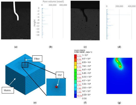
Figure 7.
10 mm sample: (a) 2D cross-section before fiber pullout; (b) 3D porosity analysis—plot of pore volume against height in specimen before fiber pullout; (c) 2D cross-section after fiber pullout; (d) 3D porosity analysis—plot of pore volume against height in specimen after fiber pullout; (e) meso-scale model; (f) stress scale; (g) FEM results—materials with permission of the authors [126].
Cementitious materials are prone to cracking under extreme events and rough environments, leading to extensive inelastic behavior. On the other hand, nucleation of cracks in heterogeneous materials such as concrete usually occurs at the meso-scale around the weakest areas—the interfacial transition zones (ITZs)—between aggregates and the surrounding cementitious mass or matrix [129]. It is reasonable to implement such zones in the models being built. The real thickness of ITZ in concrete has been found to be around 10–50 μm [103,130]. Due to the grid size, an ITZ thickness of 100–800 µm is assumed for meso-scale summation [131,132], although the studies indicate the introduction of ITZ with a thickness up to 1 mm [133]. It has been shown that changing the thickness of the ITZ has a negligible effect on the results obtained [134]. Given the size of the ITZ, meshing models in FEM can be problematic [135]. A good description of the meshing ITZ method is presented in [136]. The numerical tests demonstrated that using solid wedge elements to depict the ITZ in concrete effectively captures the distinctive behavior of concrete under tension, including the nonlinear response before reaching the maximum stress and the decrease in strength caused by the formation and progression of microcracks in the ITZ and mortar. In [137], two meso-scale 2D models were generated based on µCT studies. Two approaches were utilized: a continuous approach and a discrete approach. Attention was paid to the shape of the fracture zone between the aggregate grains. In addition, the influence of the properties of interfacial transitional zones on fracture was investigated. DEM offered valuable insights into the fracture progression, including both micro and macro cracks. The research revealed that the mechanical properties of ITZs have a significant impact on the overall strength and macrocracking of the material, highlighting the importance of conducting experimental studies, creating 3D models, and considering small grain size in DEM calculations. The evaluation of poorly characterized ITZ influences the strength of concrete [138], but the elastic modulus of concrete is insensitive to the strength of ITZ/aggregate [139]. In [139] it was pointed out that heterogeneity in the ITZ/mortar has no obvious effect on the mechanical behavior of the concrete and elastic modulus of concrete is insensitive to the strength of ITZ/ aggregate. The ITZ zone is shown in Figure 7e.
Another method that is being developed is differential quadrature method (DQM). DQM was first proposed by Bellman and his associates in the early 1970s. The method is mainly based on the idea of Taylor series expansion. The temperature-dependent nonlinear dynamic stability of the functionally graded CNT reinforced visco-plate was present in [140]. The method was used for buckling analysis [141]. The results obtained through DQM have been found to match well with those generated by the popular finite element method (FEM) and the ANSYS software. This suggests that DQM can be used as a substitute for the commonly used FEM.
Simulations of damage mechanisms were also performed using the finite difference method (FDM) [142]. The authors analyzed the effect of loads on a coal sample. The authors noted the impossibility of introducing all discontinuities into the model. Another method practiced for foamed concrete was the discrete lattice model (DLM). In the lattice model, the continuum is schematized as a set of beam elements that can transfer axial and shear forces and bending moment [143]. The discrete element method (DEM) also offers a practical approach to the issue. DEM is a set of numerical methods and algorithms aimed at calculating the physical properties of a large number of objects in free motion. DEM allows for determining the trajectories of particle motion and interactions between elements of discrete media. The application of DEM for concretes is presented together with the algorithms in [144]. The paper [145] presented a method in which laser scanning was used to map the geometry of the aggregate. Using DEM, it was shown that the failure behavior of the degree of concrete and the damage of different components under dynamic tensile loading are influenced by the ratio of aggregate strength to mortar strength. Other studies (FEM) [146] showed that the morphology of the aggregate has a non-negligible influence on post-peak mechanical behavior, the orientation of the aggregate affects the initiation and propagation and self-restraint stresses reduce the strength of concrete. Paper [147] presents meso-scale thermomechanical analyses of plain concrete based on DEM. Very high accuracy with the experiment was obtained at temperatures up to 550°C. The authors proved that the developed 2D meso-scale DEM model is reasonably accurate in predicting the transient thermo-mechanical behavior of concrete. More implementations with listed constitutive models are shown in Table 3.
Table 3.
Application of numerical methods with a focus on constitutive models.
4. Summary
This paper analyzes the state of the art in data acquisition and modeling of mechanisms occurring in cementitious material samples. The main focus of the discussion is on the use of µCT in the acquisition of geometry data. In situ µCT studies were indicated as a potential source of information on the failure mechanism. Next, the main currents in computational methods that allow meso-scale analyses of cementitious materials were indicated. On the basis of the available studies, the following summary can be formulated.
X-ray projections provide basic information about the structure of a material. X-rays are the main and leading tool in non-destructive 3D imaging methods. X-ray projections are based on basic principles of physics and can easily indicate potential damage in a sample. Measured absorbance is a function mainly of the density and atomic number of the material. Additionally, projections made correctly can be used as an input for 3D reconstruction, where CT scans are involved. Modern µCT is a high-precision method. Today’s devices can image cores 5 cm in diameter with an accuracy of 25–50 µm. The data obtained provide accurate information about the structure of cementitious materials. The use of high-contrast detectors influences the ability to distinguish between materials of different densities. The reconstructed data sets allow for analysis of porosity or distribution. Data acquired by µCT allow for precise mapping of the sample. Geometric data were very detailed. The cited studies indicate paths that allow the generation of finite element meshes or the use of Voronoi cells. Geometric models and their numerical counterparts allow simulation of phenomena occurring in the material.
In situ testing in CT can indicate additional relationships in the destruction processes of many materials, including cementitious materials. The innovative research path allows for the calibration of models with real data. The correlation is made between the results of a simulation based on the geometry of a specific sample together with experimental data. This action affects the maximum model match. Meso-scale modeling techniques can be divided into continuous and discrete methods. Numerical methods have developed a large number of constitutive models. The literature indicates high accuracy in the calculations. Meso-scale FEM models require the use of ITZ. Models developed with high accuracy require significant computational resources. The number of elements increases abruptly as the analyzed volume increases. Meso-scale models allow simulation of phenomena occurring in the structure of cementitious materials. In the near future, it is not expected to be possible to simulate full meso-scale structures. With the development of hardware, it will be possible to use tomographic analyses to determine porosity conditions and material distribution for simulations using meso-scale elements. At present, in special cases, it is possible to make the overall parameter in the material model dependent on the actual value of, for example, porosity.
The model calibration should start with the correct acquisition of geometric data. Given the purpose factor and voxel size information, the first scan of the sample can be done outside the in situ loadcell device. A direct scan will improve data quality and accuracy. Subsequent CT scans can take place at next force levels. After gaining information about a given sample, two approaches are possible: a) mapping the sample as a mesh, taking into account the geometry of the whole sample—selected aggregate and pores, or b) compiling statistical data and further generating models (e.g., Voronoi tessellation). The first approach will provide the ability to compare numerical results with in situ µCT studies. Statistically generated models can also be used, and calibration will refer to maximum strengths. Mesh-based numerical models (FEM, FDM, DQM) allow the generation of 3D elements with a high representation of the actual geometry. These methods allow accurate calibration with the obtained in situ µCT results. However, when using statistical data, it is worth using the advantages of discrete methods (DEM). However, there is still a lack of studies that directly compare the two approaches in tests.
Author Contributions
Conceptualization G.P.K. and M.C.; methodology, G.P.K.; formal analysis, G.P.K.; investigation, G.P.K.; resources M.C.; data curation, G.P.K.; writing—original draft preparation, G.P.K.; writing—review and editing, M.C.; visualization, G.P.K.; supervision, M.C.; project administration, G.P.K. and M.C. All authors have read and agreed to the published version of the manuscript.
Funding
This research received no external funding.
Institutional Review Board Statement
Not applicable.
Informed Consent Statement
Not applicable.
Data Availability Statement
The data that support the findings of this study are available from the corresponding author upon request.
Conflicts of Interest
The authors declare no conflict of interest.
References
- Minwuye Mesfin, W.; Kim, T.; Cho, S.; Kim, H.-K. Estimation of concrete strength using thermography integrated with deep-learning-based image segmentation: Case studies and economic analysis. Expert Syst. Appl. 2022, 213, 119249. [Google Scholar] [CrossRef]
- Ankamma, V.; Srujan Kumar, A. Investigation study of enhance the strength by using hybrid nano-composites on conventional cement concrete. Mater. Today Proc. 2022, 72, 2939–2945. [Google Scholar] [CrossRef]
- Zeng, Z.; Zhu, Z.; Yao, W.; Wang, Z.; Wang, C.; Wei, Y.; Wei, Z.; Guan, X. Accurate prediction of concrete compressive strength based on explainable features using deep learning. Constr. Build. Mater. 2022, 329, 127082. [Google Scholar] [CrossRef]
- Dybeł, P. Effect of bottom-up placing of self-compacting concrete on microstructure of rebar-concrete interface. Constr. Build. Mater. 2021, 299, 124359. [Google Scholar] [CrossRef]
- Dybeł, P.; Kucharska, M. X-ray CT Investigation of Bond Mechanism in Reinforced SCC Elements of Different Placement Technology. Materials 2021, 14, 6236. [Google Scholar] [CrossRef]
- Frazão, C.; Díaz, B.; Barros, J.; Bogas, J.A.; Toptan, F. An experimental study on the corrosion susceptibility of Recycled Steel Fiber Reinforced Concrete. Cem. Concr. Compos. 2019, 96, 138–153. [Google Scholar] [CrossRef]
- Wałach, D. Analysis of factors affecting the environmental impact of concrete structures. Sustainability 2021, 13, 204. [Google Scholar] [CrossRef]
- Flatt, R.J.; Wangler, T. On sustainability and digital fabrication with concrete. Cem. Concr. Res. 2022, 158, 106837. [Google Scholar] [CrossRef]
- Jaskowska-Lemanska, J. Impurities of recycled concrete aggregate—Types, origin and influence on the concrete strength parameters. IOP Conf. Ser. Mater. Sci. Eng. 2019, 603, 042056. [Google Scholar] [CrossRef]
- Algourdin, N.; Pliya, P.; Beaucour, A.L.; Simon, A.; Noumowé, A. Influence of polypropylene and steel fibres on thermal spalling and physical-mechanical properties of concrete under different heating rates. Constr. Build. Mater. 2020, 259, 119690. [Google Scholar] [CrossRef]
- Du, Y.; Qi, H.H.; Huang, S.S.; Richard Liew, J.Y. Experimental study on the spalling behaviour of ultra-high strength concrete in fire. Constr. Build. Mater. 2020, 258, 120334. [Google Scholar] [CrossRef]
- Hager, I.; Mróz, K. Role of Polypropylene Fibres in Concrete Spalling Risk Mitigation in Fire and Test Methods of Fibres Effectiveness Evaluation. Materials 2019, 12, 3869. [Google Scholar] [CrossRef]
- Mach, A. Analysis of the Possibility of Developing “Earthship” Autonomous Buildings. Civ. Environ. Eng. Reports 2022, 32, 1–18. [Google Scholar] [CrossRef]
- Chung, S.Y.; Kim, J.S.; Stephan, D.; Han, T.S. Overview of the use of micro-computed tomography (micro-CT) to investigate the relation between the material characteristics and properties of cement-based materials. Constr. Build. Mater. 2019, 229, 116843. [Google Scholar] [CrossRef]
- Stec, J.; Tarasiuk, J.; Nagy, S.; Smulski, R.; Gluch, J.; Filipek, R. Non-destructive investigations of pore morphology of micropore carbon materials. Ceram. Int. 2019, 45, 3483–3491. [Google Scholar] [CrossRef]
- Stock, S.R. X-ray microtomography of materials. Int. Mater. Rev. 1999, 44, 141–164. [Google Scholar] [CrossRef]
- Dewulf, W.; Bosse, H.; Carmignato, S.; Leach, R. Advances in the metrological traceability and performance of X-ray computed tomography. CIRP Ann. 2022, 71, 693–716. [Google Scholar] [CrossRef]
- Burgmann, S.; Godehardt, M.; Schladitz, K.; Breit, W. Influence of voxel size for µCT imaging of particles on measurement accuracy. Constr. Build. Mater. 2021, 289, 123148. [Google Scholar] [CrossRef]
- Elkhoury, J.E.; Shankar, R.; Ramakrishnan, T.S. Resolution and Limitations of X-ray Micro-CT with Applications to Sandstones and Limestones. Transp. Porous Media 2019, 129, 413–425. [Google Scholar] [CrossRef]
- Cierniak, R. X-ray Computed Tomography in Biomedical Engineering; Springer: London, UK, 2011; ISBN 978-0-85729-026-7. [Google Scholar]
- Carmignato, S.; Dewulf, W.; Leach, R. (Eds.) Industrial X-ray Computed Tomography; Springer International Publishing: Cham, Switzerland, 2018; ISBN 978-3-319-59571-9. [Google Scholar]
- Brisard, S.; Serdar, M.; Monteiro, P.J.M. Multiscale X-ray tomography of cementitious materials: A review. Cem. Concr. Res. 2020, 128. [Google Scholar] [CrossRef]
- Martz, H.E.; Logan, C.M.; Schneberk, D.J.; Shull, P.J. X-ray Imaging; CRC Press: Boca Raton, FL, USA, 2016; ISBN 9781420009767. [Google Scholar]
- Seeram, E. Computed Tomography—Physical Principles, Patient Care, Clinical Applications, and Quality Control; Saunders: Philadelphia, PA, USA, 2022; ISBN 9780323790635. [Google Scholar]
- Ramachandran, G.N.; Lakshminarayanan, A.V. Three-dimensional reconstruction from radiographs and electron micrographs: Application of convolutions instead of Fourier transforms. Proc. Natl. Acad. Sci. USA 1971, 68, 2236–2240. [Google Scholar] [CrossRef] [PubMed]
- Vidal, F.P.; Mitchell, I.T.; Létang, J.M. Use of fast realistic simulations on GPU to extract CAD models from microtomographic data in the presence of strong CT artefacts. Precis. Eng. 2022, 74, 110–125. [Google Scholar] [CrossRef]
- Herman, G.T. Fundamentals of Computerized Tomography; Advances in Pattern Recognition; Springer: London, UK, 2009; ISBN 978-1-85233-617-2. [Google Scholar]
- Gottleib, D.; Gustafsson, B.; Forssen, P. On the direct Fourier method for computer tomography. IEEE Trans. Med. Imaging 2000, 19, 223–232. [Google Scholar] [CrossRef] [PubMed]
- Zhang, H.; He, H.; Gao, Y.; Mady, A.; Filipović, V.; Dyck, M.; Lv, J.; Liu, Y. Applications of Computed Tomography (CT) in environmental soil and plant sciences. Soil Tillage Res. 2023, 226, 105574. [Google Scholar] [CrossRef]
- Cao, W.; Sun, T.; Kerckhofs, G.; Fardell, G.; Price, B.; Dewulf, W. A simulation-based study on the influence of the X-ray spectrum on the performance of multi-material beam hardening correction algorithms. Meas. Sci. Technol. 2018, 29, 095002. [Google Scholar] [CrossRef]
- Gordon, R.; Bender, R.; Herman, G.T. Algebraic Reconstruction Techniques (ART) for three-dimensional electron microscopy and X-ray photography. J. Theor. Biol. 1970, 29, 471–481. [Google Scholar] [CrossRef]
- Raparia, D.; Alessi, J.; Kponou, A. The Algebraic Reconstruction Technique (ART). In Proceedings of the 1997 Particle Accelerator Conference, Vancouver, BC, Canada, 12–16 May 1997; p. 3. [Google Scholar]
- Steuwe, A.; Weber, M.; Bethge, O.T.; Rademacher, C.; Boschheidgen, M.; Sawicki, L.M.; Antoch, G.; Aissa, J. Influence of a novel deep-learning based reconstruction software on the objective and subjective image quality in low-dose abdominal computed tomography. Br. J. Radiol. 2021, 94, 20200677. [Google Scholar] [CrossRef]
- Franck, C.; Zhang, G.; Deak, P.; Zanca, F. Preserving image texture while reducing radiation dose with a deep learning image reconstruction algorithm in chest CT: A phantom study. Phys. Medica 2021, 81, 86–93. [Google Scholar] [CrossRef]
- Urikura, A.; Yoshida, T.; Nakaya, Y.; Nishimaru, E.; Hara, T.; Endo, M. Deep learning-based reconstruction in ultra-high-resolution computed tomography: Can image noise caused by high definition detector and the miniaturization of matrix element size be improved? Phys. Medica 2021, 81, 121–129. [Google Scholar] [CrossRef]
- Higaki, T.; Nakamura, Y.; Zhou, J.; Yu, Z.; Ms, T.N.; Tatsugami, F.; Awai, K. Deep Learning Reconstruction at CT. Acad. Radiol. 2019, 27, 82–87. [Google Scholar]
- Trofimov, A.; Mishurova, T.; Lanzoni, L.; Radi, E.; Bruno, G.; Sevostianov, I. Microstructural analysis and mechanical properties of concrete reinforced with polymer short fibers. Int. J. Eng. Sci. 2018, 133, 210–218. [Google Scholar] [CrossRef]
- Naresh, K.; Khan, K.A.; Umer, R.; Cantwell, W.J. The use of X-ray computed tomography for design and process modeling of aerospace composites: A review. Mater. Des. 2020, 190, 108553. [Google Scholar] [CrossRef]
- Bossa, N.; Chaurand, P.; Vicente, J.; Borschneck, D.; Levard, C.; Aguerre-Chariol, O.; Rose, J. Micro- and nano-X-ray computed-tomography: A step forward in the characterization of the pore network of a leached cement paste. Cem. Concr. Res. 2015, 67, 138–147. [Google Scholar] [CrossRef]
- Zhang, M.; Jivkov, A.P. Microstructure-informed modelling of damage evolution in cement paste. Constr. Build. Mater. 2014, 66, 731–742. [Google Scholar] [CrossRef]
- Burlion, N.; Bernard, D.; Chen, D. X-ray microtomography: Application to microstructure analysis of a cementitious material during leaching process. Cem. Concr. Res. 2006, 36, 346–357. [Google Scholar] [CrossRef]
- Zou, C.; Long, G.; Zeng, X.; Ma, K.; Xie, Y. Hydration and multiscale pore structure characterization of steam-cured cement paste investigated by X-ray CT. Constr. Build. Mater. 2021, 282, 122629. [Google Scholar] [CrossRef]
- Wu, Z.; Wei, Y.; Wang, S.; Chen, J. Application of X-ray Micro-CT for Quantifying Degree of Hydration of Slag-Blended Cement Paste. J. Mater. Civ. Eng. 2020, 32, 1–16. [Google Scholar] [CrossRef]
- Liu, P.; Chen, Y.; Sha, F.; Yu, Z.; Shao, G. Study on micro structure and composition distribution of concrete surface zone based on fractal theory and XCT technology. Constr. Build. Mater. 2020, 263, 120209. [Google Scholar] [CrossRef]
- Kim, H.-T.; Park, K. Computed tomography (CT) Image-based analysis of concrete microstructure using virtual element method. Compos. Struct. 2022, 299, 115937. [Google Scholar] [CrossRef]
- Maaroufi, M.; Abahri, K.; El Hachem, C.; Belarbi, R. Characterization of EPS lightweight concrete microstructure by X-ray tomography with consideration of thermal variations. Constr. Build. Mater. 2018, 178, 339–348. [Google Scholar] [CrossRef]
- Korat, L.; Ducman, V.; Legat, A.; Mirtič, B. Characterisation of the pore-forming process in lightweight aggregate based on silica sludge by means of X-ray micro-tomography (micro-CT) and mercury intrusion porosimetry (MIP). Ceram. Int. 2013, 39, 6997–7005. [Google Scholar] [CrossRef]
- Nguyen, T.; Ghazlan, A.; Kashani, A.; Bordas, S.; Ngo, T. 3D meso-scale modelling of foamed concrete based on X-ray Computed Tomography. Constr. Build. Mater. 2018, 188, 583–598. [Google Scholar] [CrossRef]
- Chung, S.-Y.; Lehmann, C.; Abd Elrahman, M.; Stephan, D. Pore Characteristics and Their Effects on the Material Properties of Foamed Concrete Evaluated Using Micro-CT Images and Numerical Approaches. Appl. Sci. 2017, 7, 550. [Google Scholar] [CrossRef]
- Wang, P.; Qiao, H.; Zhang, Y.; Li, Y.; Feng, Q.; Chen, K. Meso-damage evolution analysis of magnesium oxychloride cement concrete based on X-CT and grey-level co-occurrence matrix. Constr. Build. Mater. 2020, 255, 119373. [Google Scholar] [CrossRef]
- Hong, S.; Shi, G.; Zheng, F.; Liu, M.; Hou, D.; Dong, B. Characterization of the corrosion profiles of reinforcement with different impressed current densities by X-ray micro-computed tomography. Cem. Concr. Compos. 2020, 109, 103583. [Google Scholar] [CrossRef]
- Wang, X.; Jin, Z.; Liu, J.; Chen, F.; Feng, P.; Tang, J. Research on internal monitoring of reinforced concrete under accelerated corrosion, using XCT and DIC technology. Constr. Build. Mater. 2021, 266, 121018. [Google Scholar] [CrossRef]
- Kong, W.; Wei, Y.; Wang, S.; Chen, J.; Wang, Y. Research progress on cement-based materials by X-ray computed tomography. Int. J. Pavement Res. Technol. 2020, 13, 366–375. [Google Scholar] [CrossRef]
- Sadowski, Ł.; Stefaniuk, D. The effect of surface treatment on the microstructure of the skin of concrete. Appl. Surf. Sci. 2018, 427 Pt B, 934–941. [Google Scholar] [CrossRef]
- Shi, P.F.; Yang, Y.F.; Gao, Y.; Liu, J.H. Analysis of concrete meso damage based on CT. MATEC Web Conf. 2015, 31, 3–6. [Google Scholar] [CrossRef]
- Stefaniuk, D.; Tankiewicz, M.; Stróżyk, J. X-ray Microtomography (μCT) as a Useful Tool for Visualization and Interpretation of Shear Strength Test Results. Stud. Geotech. Mech. 2015, 36, 47–55. [Google Scholar] [CrossRef]
- Tian, W.; Han, N. Pore characteristics (>0.1 mm) of non-air entrained concrete destroyed by freeze-thaw cycles based on CT scanning and 3D printing. Cold Reg. Sci. Technol. 2018, 151, 314–322. [Google Scholar] [CrossRef]
- Skarżyński, Ł.; Suchorzewski, J. Mechanical and fracture properties of concrete reinforced with recycled and industrial steel fibers using Digital Image Correlation technique and X-ray micro computed tomography. Constr. Build. Mater. 2018, 183, 283–299. [Google Scholar] [CrossRef]
- du Plessis, A.; Boshoff, W.P. A review of X-ray computed tomography of concrete and asphalt construction materials. Constr. Build. Mater. 2019, 199, 637–651. [Google Scholar] [CrossRef]
- Zhang, P.; Wittmann, F.H.; Lura, P.; Müller, H.S.; Han, S.; Zhao, T. Application of neutron imaging to investigate fundamental aspects of durability of cement-based materials: A review. Cem. Concr. Res. 2018, 108, 152–166. [Google Scholar] [CrossRef]
- Kichanov, S.E.; Nazarov, K.M.; Kozlenko, D.P.; Balasoiu, M.; Nicu, M.; Ionascu, L.; Dragolici, A.C.; Dragolici, F.; Savenko, B.N. Neutron tomography studies of cement-based materials used for radioactive waste conditioning. Rom. J. Phys. 2019, 62, 9. [Google Scholar]
- Suzuki, Y.; Cousins, D.S.; Dorgan, J.R.; Stebner, A.P.; Kappes, B.B. Dual-energy X-ray computed tomography for void detection in fiber-reinforced composites. J. Compos. Mater. 2019, 53, 2349–2359. [Google Scholar] [CrossRef]
- Liu, J.; Ba, M.; Du, Y.; He, Z.; Chen, J. Effects of chloride ions on carbonation rate of hardened cement paste by X-ray CT techniques. Constr. Build. Mater. 2016, 122, 619–627. [Google Scholar] [CrossRef]
- Ranjbar, N.; Kuenzel, C.; Gundlach, C.; Kempen, P.; Mehrali, M. Halloysite reinforced 3D-printable geopolymers. Cem. Concr. Compos. 2023, 136, 104894. [Google Scholar] [CrossRef]
- Zhou, W.; Zhang, Y.; Ma, L.; Li, V.C. Influence of printing parameters on 3D printing engineered cementitious composites (3DP-ECC). Cem. Concr. Compos. 2022, 130, 104562. [Google Scholar] [CrossRef]
- Pasek, R.; Jaskowska-Lemańska, J.; Wałach, D.; Rokita, T.; Kamiński, P. Evaluation of Technical Condition and Durability of Wooden Shaft Guides with Application of Non-Destructive and Semi-Destructive Testing Methods. Materials 2022, 15, 4769. [Google Scholar] [CrossRef]
- Xue, P.; Fu, Y.; Zhang, J.; Ma, L.; Ren, M.; Zhang, Z.; Dong, E. Effective lung ventilation estimation based on 4D CT image registration and supervoxels. Biomed. Signal Process. Control 2023, 79, 104074. [Google Scholar] [CrossRef]
- Kuo, L.E.; Bird, S.H.; Lubitz, C.C.; Pandian, T.K.; Parangi, S.; Stephen, A.E. Four-dimensional computed tomography (4D-CT) for preoperative parathyroid localization: A good study but are we using it? Am. J. Surg. 2022, 223, 694–698. [Google Scholar] [CrossRef]
- Wang, Q.; Guo, X.; Stäb, D.; Jin, N.; Poon, E.K.W.; Lim, R.P.; Ooi, A. Computational fluid dynamic simulations informed by CT and 4D flow MRI for post-surgery aortic dissection—A case study. Int. J. Heat Fluid Flow 2022, 96, 108986. [Google Scholar] [CrossRef]
- Dybeł, P.; Wałach, D. Evaluation of the Development of Bond Strength between Two Concrete Layers. IOP Conf. Ser. Mater. Sci. Eng. 2017, 245, 032056. [Google Scholar] [CrossRef]
- Zheng, Y.; Zhang, Y.; Zhuo, J.; Zhang, Y.; Wan, C. A review of the mechanical properties and durability of basalt fiber-reinforced concrete. Constr. Build. Mater. 2022, 359, 129360. [Google Scholar] [CrossRef]
- Scott, A.E.; Sinclair, I.; Spearing, S.M.; Mavrogordato, M.N.; Hepples, W. Influence of voids on damage mechanisms in carbon/epoxy composites determined via high resolution computed tomography. Compos. Sci. Technol. 2014, 90, 147–153. [Google Scholar] [CrossRef]
- Deben UK Ltd. CT5000 5 kN In-Situ Loadcell Tensile Stage for X-ray CT Applications. Available online: https://deben.co.uk/tensile-testing/µxct/tensile-stages-for-x-ray-ct-tomography/ (accessed on 16 February 2023).
- Lorenzoni, R.; Curosu, I.; Léonard, F.; Paciornik, S.; Mechtcherine, V.; Silva, F.A.; Bruno, G. Combined mechanical and 3D-microstructural analysis of strain-hardening cement-based composites (SHCC) by in-situ X-ray microtomography. Cem. Concr. Res. 2020, 136, 106139. [Google Scholar] [CrossRef]
- Böhm, R.; Stiller, J.; Behnisch, T.; Zscheyge, M.; Protz, R.; Radloff, S.; Gude, M.; Hufenbach, W. A quantitative comparison of the capabilities of in situ computed tomography anad conventional computed tomography for damage analysis of composites. Compos. Sci. Technol. 2015, 110, 62–68. [Google Scholar] [CrossRef]
- Fang, J.X.; He, H.T.; Wang, Y.J.; Wang, J.X.; Zhang, D.B.; Cao, Y. Tensile fracture behaviors of a laser powder deposited Fe–30Mn–10Cr–10Co–3Ni high-entropy alloy: In situ X-ray computed microtomography study. Mater. Sci. Eng. A 2022, 840, 142948. [Google Scholar] [CrossRef]
- Kimura, M.; Watanabe, T.; Oshima, S.; Takeichi, Y.; Niwa, Y.; Seryo, Y.; Hojo, M. Nanoscale in situ observation of damage formation in carbon fiber/epoxy composites under mixed-mode loading using synchrotron radiation X-ray computed tomography. Compos. Sci. Technol. 2022, 230, 109332. [Google Scholar] [CrossRef]
- Oshima, S.; Mamishin, A.; Hojo, M.; Nishikawa, M.; Matsuda, N.; Kanesaki, M. High-resolution in situ characterization of micromechanisms in CFRP laminates under mode II loading. Eng. Fract. Mech. 2022, 260, 108189. [Google Scholar] [CrossRef]
- Shan, L.; Yang, H.; Guo, F.; Li, Z. Fatigue damage evolution in asphalt mixture based on X-ray CT images. Constr. Build. Mater. 2022, 358, 129242. [Google Scholar] [CrossRef]
- Duan, Y.; Feng, X.-T.; Li, X.; Yang, B. Mesoscopic damage mechanism and a constitutive model of shale using in-situ X-ray CT device. Eng. Fract. Mech. 2022, 269, 108576. [Google Scholar] [CrossRef]
- Wan, K.; Xue, X. In situ compressive damage of cement paste characterized by lab source X-ray computer tomography. Mater. Charact. 2013, 82, 32–40. [Google Scholar] [CrossRef]
- Skarżyński, Ł.; Tejchman, J. Experimental investigations of damage evolution in concrete during bending by continuous micro-CT scanning. Mater. Charact. 2019, 154, 40–52. [Google Scholar] [CrossRef]
- Zhu, L.; Dang, F.; Xue, Y.; Ding, W.; Zhang, L. Comparative study on the meso-scale damage evolution of concrete under static and dynamic tensile loading using X-ray computed tomography and digital image analysis. Constr. Build. Mater. 2020, 250, 118848. [Google Scholar] [CrossRef]
- Wang, R.Z.; Wang, C.Y.; Lin, Y.L. Numerical Model of High Strength Concrete. IOP Conf. Ser. Mater. Sci. Eng. 2018, 317, 012069. [Google Scholar] [CrossRef]
- Chen, W.-F.; Saleeb, A.F. Constitutive Equations for Engineering Materials: Elasticity and Modeling; Revised; Elsevier: Amsterdam, The Netherlands, 2013. [Google Scholar]
- Babu, R.; Benipal, G.; Singh, A. Constitutive modeling of concrete: An overview. Asian J. Civ. Eng. 2005, 6, 211–246. [Google Scholar]
- Kong, X.; Fang, Q.; Hong, J. A new damage-based nonlocal model for dynamic tensile failure of concrete material. Int. J. Impact Eng. 2019, 132, 103336. [Google Scholar] [CrossRef]
- Ince, R.; Fenerli, C. Determination of tensile strength of cementitious composites using fracture parameters of two-parameter model for concrete fracture. Constr. Build. Mater. 2022, 344, 128222. [Google Scholar] [CrossRef]
- Huang, Y.; Zhang, H.; Zhou, J.; Xu, S. Efficient quasi-brittle fracture simulations of concrete at mesoscale using micro CT images and a localizing gradient damage model. Comput. Methods Appl. Mech. Eng. 2022, 400, 115559. [Google Scholar] [CrossRef]
- Wosatko, A. Survey of Localizing Gradient Damage in Static and Dynamic Tension of Concrete. Materials 2022, 15, 1875. [Google Scholar] [CrossRef]
- Wang, J.; Poh, L.H.; Guo, X. Mixed mode fracture of geometrically similar FRUHPC notched beams with the localizing gradient damage model. Eng. Fract. Mech. 2022, 275, 108843. [Google Scholar] [CrossRef]
- Drobiec, Ł.; Jasiński, R. Adoption of the Willam-Warnke Failure Criterion for Describing Behavior of Ca-Si Hollow Blocks. Procedia Eng. 2017, 193, 470–477. [Google Scholar] [CrossRef]
- Ashrafi, E.; Farzam, M. Experimental investigation on the triaxial behavior of lightweight concrete. Constr. Build. Mater. 2021, 312, 125348. [Google Scholar] [CrossRef]
- Kim, S.H.; Chang, Y.-S.; Cho, Y.-J.; Jhung, M.J. Modeling of Reinforced Concrete for Reactor Cavity Analysis under Energetic Steam Explosion Condition. Nucl. Eng. Technol. 2016, 48, 218–227. [Google Scholar] [CrossRef]
- Wilhelm, S.; Curbach, M. Experimental and nonlinear numerical analysis of underwater housings for the deep sea, made of ultra-high performance concrete. Struct. Concr. 2017, 18, 216–224. [Google Scholar] [CrossRef]
- Dmitriev, A.; Novozhilov, Y.; Mikhalyuk, D.; Lalin, V. Calibration and Validation of the Menetrey-Willam Constitutive Model for Concrete. Stroit. Unikal’nyh Zdanij i Sooruz. St. Petersbg. 2020, 3, 1–22. [Google Scholar] [CrossRef]
- Červenka, J.; Papanikolaou, V.K. Three dimensional combined fracture–plastic material model for concrete. Int. J. Plast. 2008, 24, 2192–2220. [Google Scholar] [CrossRef]
- Pisano, A.A. An algorithmic approach for peak loadevaluation of structural elements obeying a menetrey-willam type yield criterion. Electron. J. Differ. Equ. 2012, 2012, 1–9. [Google Scholar]
- Pisano, A.A.; Fuschi, P.; De Domenico, D. Numerical limit analysis of steel-reinforced concrete walls and slabs. Comput. Struct. 2015, 160, 42–55. [Google Scholar] [CrossRef]
- Teng, G.; Zheng, C.; Chen, X.; Lan, X.; Zhu, Y.; Shan, C. Numerical fracture investigation of single-edge notched asphalt concrete beam based on random heterogeneous FEM model. Constr. Build. Mater. 2021, 304, 124581. [Google Scholar] [CrossRef]
- Sinchuk, Y.; Shishkina, O.; Gueguen, M.; Signor, L.; Nadot-Martin, C.; Trumel, H.; Van Paepegem, W. X-ray CT based multi-layer unit cell modeling of carbon fiber-reinforced textile composites: Segmentation, meshing and elastic property homogenization. Compos. Struct. 2022, 298, 116003. [Google Scholar] [CrossRef]
- Wijaya, W.; Ali, M.A.; Umer, R.; Khan, K.A.; Kelly, P.A.; Bickerton, S. An automatic methodology to CT-scans of 2D woven textile fabrics to structured finite element and voxel meshes. Compos. Part A Appl. Sci. Manuf. 2019, 125, 105561. [Google Scholar] [CrossRef]
- Thilakarathna, P.S.M.; Kristombu Baduge, K.S.; Mendis, P.; Vimonsatit, V.; Lee, H. Mesoscale modelling of concrete—A review of geometry generation, placing algorithms, constitutive relations and applications. Eng. Fract. Mech. 2020, 231, 106974. [Google Scholar] [CrossRef]
- Chen, B.; Yu, H.; Zhang, J.; Ma, H.; Tian, F. Effects of the embedding of cohesive zone model on the mesoscopic fracture behavior of Concrete: A case study of uniaxial tension and compression tests. Eng. Fail. Anal. 2022, 142, 106709. [Google Scholar] [CrossRef]
- Liu, M.; Wang, F. Numerical simulation of influence of coarse aggregate crushing on mechanical properties of concrete under uniaxial compression. Constr. Build. Mater. 2022, 342, 128081. [Google Scholar] [CrossRef]
- Guo, J.; Lin, W.; Qin, X.; Xu, Y.; Dong, K. Mesoscopic study on fracture behavior of fully graded concrete under uniaxial tension by using the phase-field method. Eng. Fract. Mech. 2022, 272, 108678. [Google Scholar] [CrossRef]
- Yu, Y.; Zheng, Y.; Zhao, X.-Y. Mesoscale modeling of recycled aggregate concrete under uniaxial compression and tension using discrete element method. Constr. Build. Mater. 2021, 268, 121116. [Google Scholar] [CrossRef]
- Ai, D.; Qiao, Z.; Wu, Y.; Zhao, Y.; Li, C. Experimental and numerical study on the fracture characteristics of concrete under uniaxial compression. Eng. Fract. Mech. 2021, 246, 107606. [Google Scholar] [CrossRef]
- Ma, Y.-X.; Zhao, O.; Tan, K.H. Experimental and numerical studies of concrete-encased concrete-filled steel tube stub columns under uniaxial and biaxial eccentric compression. Eng. Struct. 2021, 232, 111796. [Google Scholar] [CrossRef]
- Pallarés, L.; Miguel, P.F.; Fernández-Prada, M.A. A numerical method to design reinforced concrete sections subjected to axial forces and biaxial bending based on ultimate strain limits. Eng. Struct. 2009, 31, 3065–3071. [Google Scholar] [CrossRef]
- Jin, L.; Li, J.; Yu, W.; Du, X. Mesoscopic simulations on the strength and size effect of concrete under biaxial loading. Eng. Fract. Mech. 2021, 253, 107870. [Google Scholar] [CrossRef]
- Jin, L.; Li, J.; Yu, W.; Du, X. Size effect modelling for dynamic biaxial compressive strength of concrete: Influence of lateral stress ratio and strain rate. Int. J. Impact Eng. 2021, 156, 103942. [Google Scholar] [CrossRef]
- Wang, J.-J.; Liu, C.; Nie, X.; Fan, J.-S.; Zhu, Y.-J. Nonlinear model updating algorithm for biaxial reinforced concrete constitutive models of shear walls. J. Build. Eng. 2021, 44, 103215. [Google Scholar] [CrossRef]
- Zhu, X.; Chen, X.; Zhang, N.; Wang, X.; Diao, H. Experimental and numerical research on triaxial mechanical behavior of self-compacting concrete subjected to freeze–thaw damage. Constr. Build. Mater. 2021, 288, 123110. [Google Scholar] [CrossRef]
- Wolfs, R.J.M.; Bos, F.P.; Salet, T.A.M. Triaxial compression testing on early age concrete for numerical analysis of 3D concrete printing. Cem. Concr. Compos. 2019, 104, 103344. [Google Scholar] [CrossRef]
- Stamati, O.; Roubin, E.; Andò, E.; Malecot, Y.; Charrier, P. Fracturing process of micro-concrete under uniaxial and triaxial compression: Insights from in-situ X-ray mechanical tests. Cem. Concr. Res. 2021, 149, 106578. [Google Scholar] [CrossRef]
- Zhu, X.; Chen, X.; Zhang, N. Experimental and numerical investigation on cyclic triaxial behavior of self-compacting concrete subjected to freeze–thaw damage. Int. J. Fatigue 2021, 149, 106277. [Google Scholar] [CrossRef]
- Zhao, L.; Zhang, L.; Mao, J.; Liu, Z. An elastoplastic damage model of concrete under cyclic loading and its numerical implementation. Eng. Fract. Mech. 2022, 273, 108714. [Google Scholar] [CrossRef]
- Song, Z.; Konietzky, H.; Herbst, M. Three-dimensional particle model based numerical simulation on multi-level compressive cyclic loading of concrete. Constr. Build. Mater. 2019, 225, 661–677. [Google Scholar] [CrossRef]
- Paudel, S.; Tanapornraweekit, G.; Tangtermsirikul, S. Numerical investigation of concrete filled hollow precast composite columns subjected to lateral cyclic loading. Eng. Struct. 2022, 252, 113586. [Google Scholar] [CrossRef]
- Sun, B. A dimensional analysis based thermal–mechanical damage model for crack growth simulation of concrete-like materials at elevated temperatures. Constr. Build. Mater. 2022, 357, 129429. [Google Scholar] [CrossRef]
- Du, W.; Qian, C.; Xu, Y.; Wei, M.; Peng, B.; Xie, Y. Effects of ambient temperature, formwork type, and demolding time on the thermal deformation of sidewall concrete in underground engineering: Experiment, simulation, and engineering practice. Constr. Build. Mater. 2022, 353, 129083. [Google Scholar] [CrossRef]
- Martelletto, F.; Doretti, L.; Mancin, S. Numerical simulation through experimental validation of latent and sensible concrete thermal energy storage system. J. Energy Storage 2022, 51, 104567. [Google Scholar] [CrossRef]
- Bao, J.; Zheng, R.; Wei, J.; Zhang, P.; Xue, S.; Liu, Z. Numerical and experimental investigation of coupled capillary suction and chloride penetration in unsaturated concrete under cyclic drying-wetting condition. J. Build. Eng. 2022, 51, 104273. [Google Scholar] [CrossRef]
- Jia, Y.; Zhao, X.; Bian, H.; Wang, W.; Shao, J.-F. Numerical modelling the influence of water content on the mechanical behaviour of concrete under high confining pressures. Mech. Res. Commun. 2022, 119, 103819. [Google Scholar] [CrossRef]
- Kaczmarczyk, G.P.; Kinasz, R.; Bilozir, V.; Bidenko, I. Application of X-ray Computed Tomography to Verify Bond Failures Mechanism of Fiber-Reinforced Fine-Grain Concrete. Materials 2022, 15, 2193. [Google Scholar] [CrossRef]
- Park, I.; Moon, J.; Bae, S.; Oh, J.E.; Yoon, S. Application of micro-CT to Mori-Tanaka method for non-randomly oriented pores in air-entrained cement pastes. Constr. Build. Mater. 2020, 255, 119342. [Google Scholar] [CrossRef]
- Pan, T.; Chen, C.; Yu, Q. Three-dimensional micromechanical modeling of concrete degradation under multiphysics fields. Compos. Struct. 2017, 175, 7–18. [Google Scholar] [CrossRef]
- Yang, Z.-J.; Li, B.-B.; Wu, J.-Y. X-ray computed tomography images based phase-field modeling of mesoscopic failure in concrete. Eng. Fract. Mech. 2019, 208, 151–170. [Google Scholar] [CrossRef]
- Xiao, J.; Li, W.; Corr, D.J.; Shah, S.P. Effects of interfacial transition zones on the stress–strain behavior of modeled recycled aggregate concrete. Cem. Concr. Res. 2013, 52, 82–99. [Google Scholar] [CrossRef]
- Huang, Y.; Yang, Z.; Ren, W.; Liu, G.; Zhang, C. 3D meso-scale fracture modelling and validation of concrete based on in-situ X-ray Computed Tomography images using damage plasticity model. Int. J. Solids Struct. 2015, 67–68, 340–352. [Google Scholar] [CrossRef]
- Huang, Y.J.; Yang, Z.J.; Chen, X.W.; Liu, G.H. Monte Carlo simulations of meso-scale dynamic compressive behavior of concrete based on X-ray computed tomography images. Int. J. Impact Eng. 2016, 97, 102–115. [Google Scholar] [CrossRef]
- Šavija, B.; Luković, M.; Pacheco, J.; Schlangen, E. Cracking of the concrete cover due to reinforcement corrosion: A two-dimensional lattice model study. Constr. Build. Mater. 2013, 44, 626–638. [Google Scholar] [CrossRef]
- Kim, S.-M.; Abu Al-Rub, R.K. Meso-scale computational modeling of the plastic-damage response of cementitious composites. Cem. Concr. Res. 2011, 41, 339–358. [Google Scholar] [CrossRef]
- Ren, H.; Song, S.; Ning, J. Damage evolution of concrete under tensile load using discrete element modeling. Theor. Appl. Fract. Mech. 2022, 122, 103622. [Google Scholar] [CrossRef]
- Shuguang, L.; Qingbin, L. Method of meshing ITZ structure in 3D meso-level finite element analysis for concrete. Finite Elem. Anal. Des. 2015, 93, 96–106. [Google Scholar] [CrossRef]
- Skarżyński, Ł.; Nitka, M.; Tejchman, J. Modelling of concrete fracture at aggregate level using FEM and DEM based on X-ray μCT images of internal structure. Eng. Fract. Mech. 2015, 147, 13–35. [Google Scholar] [CrossRef]
- Torrence, C.E.; Trageser, J.E.; Jones, R.E.; Rimsza, J.M. Sensitivity of the strength and toughness of concrete to the properties of the interfacial transition zone. Constr. Build. Mater. 2022, 336, 126875. [Google Scholar] [CrossRef]
- Zhao, H.; Wu, Z.; Liu, A.; Zhang, L. Numerical insights into the effect of ITZ and aggregate strength on concrete properties. Theor. Appl. Fract. Mech. 2022, 120, 103415. [Google Scholar] [CrossRef]
- Kolahchi, R.; Safari, M.; Esmailpour, M. Dynamic stability analysis of temperature-dependent functionally graded CNT-reinforced visco-plates resting on orthotropic elastomeric medium. Compos. Struct. 2016, 150, 255–265. [Google Scholar] [CrossRef]
- Farrokhian, A. Buckling response of smart plates reinforced by nanoparticles utilizing analytical method. Steel Compos. Struct. 2020, 35, 1–12. [Google Scholar] [CrossRef]
- Du, F.; Wang, K.; Zhang, G.; Zhang, Y.; Zhang, G.; Wang, G. Damage characteristics of coal under different loading modes based on CT three-dimensional reconstruction. Fuel 2022, 310, 122304. [Google Scholar] [CrossRef]
- Jiang, N.; Ge, Z.; Guan, Y.; Zuo, Z.; Zhang, H.; Ling, Y.; Šavija, B. Experimentally validated meso-scale fracture modelling of foamed concrete. Theor. Appl. Fract. Mech. 2022, 122, 103631. [Google Scholar] [CrossRef]
- Ma’arif, F.; Gao, Z.; Li, F. A Review of the Discrete Element Method Application on Concrete Materials. J. Phys. Conf. Ser. 2020, 1625, 012009. [Google Scholar] [CrossRef]
- Zhou, X.; Xie, Y.; Zeng, X.; Long, G.; Wu, J.; Ma, G.; Wang, F.; Zhao, H.; Yao, L. Meso-scale numerical simulation of the effect of aggregate strength on damage and fracture of high-strength concrete under dynamic tensile loading. Theor. Appl. Fract. Mech. 2022, 122, 103551. [Google Scholar] [CrossRef]
- Qiu, W.; Ueda, T.; Fu, S.; Han, Y.; Wang, J.; Ye, J. Meso-scale computational modeling of the fracture of concrete with complex shaped aggregates under the self-restraint stress. Compos. Struct. 2023, 303, 116267. [Google Scholar] [CrossRef]
- Prakash, P.R.; Pulatsu, B.; Lourenço, P.B.; Azenha, M.; Pereira, J.M. A meso-scale discrete element method framework to simulate thermo-mechanical failure of concrete subjected to elevated temperatures. Eng. Fract. Mech. 2020, 239, 107269. [Google Scholar] [CrossRef]
- Zhang, J.; Wang, Z.; Yang, H.; Wang, Z.; Shu, X. 3D meso-scale modeling of reinforcement concrete with high volume fraction of randomly distributed aggregates. Constr. Build. Mater. 2018, 164, 350–361. [Google Scholar] [CrossRef]
- Lv, T.H.; Chen, X.W.; Chen, G. The 3D meso-scale model and numerical tests of split Hopkinson pressure bar of concrete specimen. Constr. Build. Mater. 2018, 160, 744–764. [Google Scholar] [CrossRef]
- Zhou, R.; Song, Z.; Lu, Y. 3D mesoscale finite element modelling of concrete. Comput. Struct. 2017, 192, 96–113. [Google Scholar] [CrossRef]
- Shahbeyk, S.; Hosseini, M.; Yaghoobi, M. Mesoscale finite element prediction of concrete failure. Comput. Mater. Sci. 2011, 50, 1973–1990. [Google Scholar] [CrossRef]
- Tu, Z.; Lu, Y. Mesoscale modelling of concrete for static and dynamic response analysis—Part 1: Model development and implementation. Struct. Eng. Mech. 2011, 37, 197–213. [Google Scholar] [CrossRef]
- Song, Z.; Lu, Y. Mesoscopic analysis of concrete under excessively high strain rate compression and implications on interpretation of test data. Int. J. Impact Eng. 2012, 46, 41–55. [Google Scholar] [CrossRef]
- Hao, Y.; Hao, H. Finite element modelling of mesoscale concrete material in dynamic splitting test. Adv. Struct. Eng. 2016, 19, 1027–1039. [Google Scholar] [CrossRef]
- Contrafatto, L.; Cuomo, M.; Greco, L. Meso-scale simulation of concrete multiaxial behaviour. Eur. J. Environ. Civ. Eng. 2017, 21, 896–911. [Google Scholar] [CrossRef]
- Chen, H.; Xu, B.; Wang, J.; Zhou, T.; Nie, X.; Mo, Y.L. Parametric analysis on compressive strain rate effect of concrete using mesoscale modeling approach. Constr. Build. Mater. 2020, 246, 118375. [Google Scholar] [CrossRef]
- Unger, J.F.; Eckardt, S.; Konke, C. A mesoscale model for concrete to simulate mechanical failure. Comput. Concr. 2011, 8, 401–423. [Google Scholar] [CrossRef]
- Chen, H.; Xu, B.; Mo, Y.L.; Zhou, T. Behavior of meso-scale heterogeneous concrete under uniaxial tensile and compressive loadings. Constr. Build. Mater. 2018, 178, 418–431. [Google Scholar] [CrossRef]
- Du, X.; Jin, L.; Ma, G. Numerical simulation of dynamic tensile-failure of concrete at meso-scale. Int. J. Impact Eng. 2014, 66, 5–17. [Google Scholar] [CrossRef]
- Xu, Y.; Chen, S. A method for modeling the damage behavior of concrete with a three-phase mesostructure. Constr. Build. Mater. 2016, 102, 26–38. [Google Scholar] [CrossRef]
- Tal, D.; Fish, J. Stochastic multiscale modeling and simulation framework for concrete. Cem. Concr. Compos. 2018, 90, 61–81. [Google Scholar] [CrossRef]
- Wriggers, P.; Moftah, S.O. Mesoscale models for concrete: Homogenisation and damage behaviour. Finite Elem. Anal. Des. 2006, 42, 623–636. [Google Scholar] [CrossRef]
- Jin, L.; Wang, T.; Jiang, X.; Du, X. Size effect in shear failure of RC beams with stirrups: Simulation and formulation. Eng. Struct. 2019, 199, 109573. [Google Scholar] [CrossRef]
- Ma, G.; Xie, Y.; Long, G.; Tang, Z.; Zhou, X.; Zeng, X.; Li, J. Mesoscale investigation on concrete creep behaviors based on discrete element method. Constr. Build. Mater. 2022, 342, 127957. [Google Scholar] [CrossRef]


Disclaimer/Publisher’s Note: The statements, opinions and data contained in all publications are solely those of the individual author(s) and contributor(s) and not of MDPI and/or the editor(s). MDPI and/or the editor(s) disclaim responsibility for any injury to people or property resulting from any ideas, methods, instructions or products referred to in the content. |
© 2023 by the authors. Licensee MDPI, Basel, Switzerland. This article is an open access article distributed under the terms and conditions of the Creative Commons Attribution (CC BY) license (https://creativecommons.org/licenses/by/4.0/).