Article

On Interpolative Meshless Analysis of Orthotropic Elasticity

1
School of Civil Engineering and Architecture, Wuhan University of Technology, Wuhan 430070, China
2
School of Aeronautics and Astronautics, Zhejiang University, Hangzhou 310013, China
3
School of Science, Wuhan University of Technology, Wuhan 430070, China
*
Author to whom correspondence should be addressed.
These authors contributed equally to this work.
Buildings 2023, 13(2), 387; https://doi.org/10.3390/buildings13020387
Submission received: 24 October 2022 / Revised: 17 January 2023 / Accepted: 20 January 2023 / Published: 31 January 2023
(This article belongs to the Special Issue Advanced Numerical and Computer Methods in Civil Engineering)

Abstract

:
As one possible alternative to the finite element method, the interpolation characteristic is a key property that meshless shape functions aspire to. Meanwhile, the interpolation meshless method can directly impose essential boundary conditions, which is undoubtedly an advantage over other meshless methods. In this paper, the establishment, implementation, and horizontal comparison of interpolative meshless analyses of orthotropic elasticity were studied. In addition, the radial point interpolation method, the improved interpolative element-free Galerkin method and the interpolative element-free Galerkin method based on the non-singular weight function were applied to solve orthotropic beams and ring problems. Meanwhile, the direct method is used to apply the displacement boundary conditions for orthotropic elastic problems. Finally, a detailed convergence study of the numerical parameters and horizontal comparison of numerical accuracy and efficiency were carried out. The results indicate that the three kinds of interpolative meshless methods showed good numerical accuracy in modelling orthotropic elastic problems, and the accuracy of the radial point interpolation method is the highest.

1. Introduction

Unlike finite element methods (FEM), which are currently the most widely used in engineering computational simulations, meshless/mesh-free methods employ a node-based rather than element-based approach when constructing shape functions discretizing the problem domain [1,2]. This strategy makes meshless approaches an increasingly effective substitute to finite element methods when dealing with problems involving large deformation [3,4,5,6] and crack propagation [7,8,9,10], where numerical implementations may be restricted by predefined meshes/elements. However, mainstream meshless shape functions, such as the most widely used moving least-squares approximation [1,3,4,6,7,8,10] and the reproducing kernel function [2,5,9] and their various modifications, do not have the same interpolation properties as finite element methods. For the approximate rather than interpolated meshless methods, certain kinds of additional techniques, such as the Lagrange multiplier method [1,2] and the penalty method [3,4,5,6,7,8,9,10], will necessarily be used to enforce essential boundary conditions, with some unwanted side effects in terms of computational efficiency or numerical accuracy.
Therefore, lots of research efforts have been devoted to the construction of meshless shape functions with the Kronecker delta interpolation property, so that the essential boundary conditions could be easily and directly imposed in large-scale engineering modelling. A point interpolation method whose shape function is interpolative but prone to singularity was proposed by Liu et al. [11]. Later, Wang et al. [12] proposed the radial point interpolation method (RPIM) to overcome the singularity problem of polynomial point interpolation shape functions. Ren et al. [13] proposed the interpolating moving least-squares method (IMLSM) by improving the Lancaster’s interpolative approach [14] with a singular weight function. Wang et al. [15] used the non-singular weight function to develop an improved interpolating moving least-squares method (IIMLSM) thereafter. An interpolative complex variable moving least-squares method (ICVMLSM) was developed by Deng et al. [16]. An interpolative variational multiscale element-free Galerkin method was presented by Zhang and Li [17] for convection-diffusion equations and Stokes problems. Wang et al. [18] introduced the weighted orthogonal basis in the IIMLSM to get a diagonal moment matrix. An interpolating meshless local Petrov-Galerkin method (IMLPGM) with an IMLS scheme for steady-state heat conduction problems was reported by Singh et al. [19]. Bourantas et al. [20] modified the error functional of the IMLSM to construct almost interpolating shape functions with ensured invertibility of the moment matrix. Wang et al. proposed the stable collocation method [21,22] and the gradient smooth collocation method [23].
The application of different interpolative meshless methods to analyze the mechanical response of various anisotropic elastic solids widely present in natural [24,25] and artificial [26,27] engineering materials has also received extensive attention. Dinis et al. [28] proposed the natural neighbor RPIM and used it to analyze the problems of thin plates and shells of composite materials. Njiwa et al. [29] combined isotropic boundary element and local point interpolation to solve the three-dimensional anisotropic elasticity problem. Bui and Nguyen [30] developed a novel moving Kriging interpolative scheme for efficient meshfree vibration and buckling analysis of orthotropic plates. Fallah et al. [31] used the Delaunay triangulation scheme to discretize arbitrarily distributed node sets in the domain and proposed a meshless finite volume formula to model cracks and fracture in orthotropic media. A modified interpolative element-free Galerkin method was applied to the modelling of orthotropic thermoelastic fracture by Lohit et al. [32]. Luo et al. [33] developed an efficient and stable nodal integration RPIM to evaluate the buckling performance of variable-stiffness composite plates with elliptical cutouts.
We already know that interpolation meshless methods can directly impose essential boundary conditions, which is undoubtedly an advantage over other meshless methods. Therefore, the purpose of this paper is to compare the proposed meshless interpolation methods horizontally, so as to find out which meshless interpolation method has better accuracy, which is meaningful. In this study, one mature and two relatively fresh interpolating meshless methods, namely the RPIM, the IMLSM and the IIMLSM, are employed to construct interpolative shape functions of the displacement field of orthotropic elastic solids. The corresponding formulas of the radial point interpolative meshless method (RPIM), the interpolative element-free Galerkin method (IEFGM) and the improved interpolative element-free Galerkin method (IIEFGM) for orthotropic elasticity are established and the computer programs are developed. In implementations of all three interpolative meshless orthotropic elastic analyses, the displacement boundary conditions are imposed by the direct method. Three typical numerical examples are analyzed for verification purpose and to compare the differences in numerical performance between the three methods. Finally, we find that the three meshless interpolation methods have good numerical accuracy in the modeling of orthotropic elastic problems, and the radial point interpolation method has the highest accuracy.

2. Basics of Three Interpolative Meshless Shape Functions

Here we briefly review the three schemes, i.e., the RPIM [12], the IMLSM [13] and the IIMLSM [15], to construct the interpolative meshless shape function u h ( x ) of the displacement field u(x) in the local domain of point x with n nodes xI. Hereinafter, p or p i ( x ) ( i = 1 , 2 , 3 , , m ) are used to represent the vector of m-term polynomial basis.

2.1. Radial Point Interpolation Method (RPIM)

The interpolative function u h ( x ) in the local domain could be constructed by the linear superposition of the radial basis and the polynomial basis as follows [12]:
u h ( x ) = i = 1 n r i ( x ) a i ( x ) + j = 1 m p j ( x ) b j ( x ) = r a + p b
where r is the vector of n-term radial basis, and a and b are the coefficients corresponding to two kinds of basis. The generally adopted multiquadric (MQ) basis [34] is also employed,
r i ( x ) = ( c 2 + x x I 2 ) q
where q and c are two coefficients.
Let the interpolation function u h ( x ) take the value of nodal displacement at each node, i.e.,
u = R a + P b
where u is the nodal displacement vector, and P = [ p 1 p 2 p n ] T and R = [ r 1 r 2 r n ] T are nodal basis matrices. With an extra constraint P T a = 0 , the unknown coefficient vectors a and b can be written as
a = [ R 1 R 1 P ( P T R 1 P ) 1 P T R 1 ] u
b = ( P T R 1 P ) 1 P T R 1 u
Substituting Equations (4) and (5) into Equation (1) can yield
u h ( x ) = Φ ( x ) u
where Φ ( x ) is the shape function of RPIM,
Φ ( x ) = r [ R 1 R 1 P ( P T R 1 P ) 1 P T R 1 ] + p ( P T R 1 P ) 1 P T R 1

2.2. Improved Interpolating Moving Least-Squares Method (IMLSM)

To construct interpolative moving least-squares shape functions, Ren et al. [13] employed a strategy to rebuild basis functions with a singular weight function ω ¯ ( x , x I ) . The local interpolating function u h ( x ) of the IMLSM is
u h ( x ) = p ¯ 1 ( x ) a ¯ 1 ( x ) + i = 2 m p ¯ i ( x ) a ¯ i ( x ) = p ¯ 1 ( x ) a ¯ 1 ( x ) + p ¯ a ¯
where a ¯ is the unknown coefficient vector, and the reformed basis function p ¯ i ( x ) ( i = 1 , 2 , 3 , , m ) is reconstructed from the corresponding polynomial basis p i ( x ) as follows:
p ¯ i ( x ) = 1 I = 1 n ω ¯ ( x , x I ) 1 / 2 i = 1 p i ( x ) I = 1 n γ ( x , x I ) p i ( x I ) i = 2 , 3 , , m
where γ ( x , x I ) = ω ¯ ( x , x I ) / J = 1 n ω ¯ x , x J . The singular weight function ω ¯ ( x , x I ) is
ω ¯ ( x , x I ) = x x I ρ I α x - x I ρ I 0 others
where ρ I = d max d c is the characteristic radius of the local support domain of point x, d m a x is the scale factor to control the size of the local domain, d c is the characteristic node spacing, and the parameter α is an even number and takes a value larger than zero in general.
Minimize the weighted error functional J = I = 1 n ω ¯ ( x , x I ) [ u h ( x I ) u ( x I ) ] 2 , and consider additional constraint I = 1 n ω ¯ x , x I γ ( x , x I ) u I p ¯ i = 0 to establish a group of algebraic equations to obtain the unknown coefficient term a ¯ as
p ¯ 1 ( x ) a ¯ 1 ( x ) = I = 1 n γ ( x , x I ) u I
a ¯ = A 1 B u
where A = B P ¯ 0 T , and the elements of the matrix B ( m 1 ) × n and the matrix P ¯ 0 are
B k J = ω ¯ ( x , x J ) p ¯ k ( x J ) x x J γ ( x , x J ) I = 1 , I J n ω ¯ ( x , x I ) p k ( x J ) p k ( x I ) x = x J
P ¯ 0 = p ¯ 2 ( x , x 1 ) p ¯ 2 ( x , x 2 ) p ¯ 2 ( x , x n ) p ¯ 3 ( x , x 1 ) p ¯ 3 ( x , x 2 ) p ¯ 3 ( x , x n ) p ¯ m ( x , x 1 ) p ¯ m ( x , x 2 ) p ¯ m ( x , x n )
Substituting Equations (11) and (12) into Equation (8), the interpolative function can be rewritten as
u h ( x ) = I = 1 n Φ I ( x ) u I = Φ ( x ) u
where the shape function of IMLSM is
Φ ( x ) = ( Φ 1 ( x ) , Φ 2 ( x ) , , Φ n ( x ) ) = γ + p ¯ A 1 B
γ = ( γ ( x , x 1 ) , γ ( x , x 2 ) , , γ ( x , x n ) )

2.3. Improved Interpolating Moving Least-Squares Method (IIMLSM)

To remove the unwanted singular weight function in practice, some modifications are made to the field variable function u ( x ) and the basis function in the IIMLSM by Wang et al. [15]. The transformed field variable function is written as
u ˜ ( x ) = u ( x ) I = 1 n γ ˜ ( x , x I ) u ( x I )
where γ ˜ ( x , x I ) = ζ ( x , x I ) / J = 1 n ζ ( x , x J ) and ζ x , x I = J I ( x x I 2 / x I x J 2 ) . Its local moving least-squares interpolation is defined as
u ˜ x h ( x ) = i = 2 m p ˜ i ( x ) a ˜ i ( x ) = p ˜ a ˜
The modified basis function p ˜ is constructed from the original polynomial basis as
p ˜ i ( x ) = p i ( x ) I = 1 n γ ˜ ( x , x I ) p i ( x I )
where apparently p ˜ 1 ( x ) = 0 .
To minimize the weighted discrete error norm J = I = 1 n ω ( x x I ) [ u ˜ x h ( x I ) u ˜ ( x I ) ] 2 , the unknown coefficient a ˜ could be expressed as
a ˜ = A ˜ 1 B ˜ u
where A ˜ = P ˜ 0 T ω P ˜ 0 , B ˜ = P ˜ 0 T W ( I Y ˜ ) , ω = dig [ ω ( x x 1 ) ω ( x x n ) ] , I is the identity matrix, ω ( x x I ) can take any non-singular weight function, P ˜ 0 is the n × ( m 1 ) matrix of the nodal basis row vector p ˜ , and Y ˜ is the n × n matrix of the row vector γ ˜ ( x , x I ) .
Substituting Equation (21) into Equation (18), the IIMLS interpolation u h ( x ) of u(x) is
u h ( x ) = Φ ( x ) u
where the IIMLS shape function Φ ( x ) is
Φ ( x ) = γ ˜ + p ˜ A ˜ 1 B ˜
γ ˜ = ( γ ˜ ( x , x 1 ) , γ ˜ ( x , x 2 ) , , γ ˜ ( x , x n ) )

3. The Establishment of Discrete Equations

The three meshless interpolative methods, namely the RPIM, the IMLSM, and the IIMLSM, are used to approximate orthotropic elastic displacement fields and to discretize the Galerkin weak form of control equation. The corresponding radial point interpolative meshless method (RPIM), the interpolative element-free Galerkin method (IEFGM) and the improved interpolative element-free Galerkin method (IIEFGM) for orthotropic elastic problems are presented. The Galerkin weak form of control equation for orthotropic elasticity can be written as
Ω δ ( L u ) T D ( L u ) d Ω Ω δ u T b d Ω Γ t δ u T t ¯ d Γ = 0
where L is the partial differential operator, D is the orthotropic elastic matrix, u is the column of the nodal displacement, b and t ¯ are the columns corresponding to the body force and the surface traction, respectively, and Ω and Γ t represent the problem domain and the force boundary, respectively.
The constitutive matrix of orthotropic material is represented as
D = s 11 s 12 0 s 21 s 22 0 0 0 s 66 1
where s i j is the orthotropic elastic compliance coefficient.
Discretizing Equation (25), we can get
K U = F
where U is the column of the total displacement, and the overall stiffness matrix K and the total external force vector F could be assembled from the nodal values, respectively, as follows:
K I J = Ω B I T D B J d Ω
F I = Ω Φ I T b d Ω + Γ t Φ I T t ¯ d Γ
where Φ I = Φ I 0 0 Φ I , Β I T = Φ I . 1 0 Φ I . 2 0 Φ I . 2 Φ I . 1 .
The interpolative shape functions of the above three methods can be used in meshless methods to impose displacement boundary conditions as easily as in the finite element methods. In the following three numerical examples, the interpolative meshless methods adopt the direct method to apply the corresponding essential boundary conditions. The principle of the direct method is to recombine the equations according to the determined and undetermined nodal displacements:
K a a K a b K b a K b b u a u b = f a f b
where ua and ub are the unknown and the known nodal displacements, respectively. The overall stiffness matrix and the total external force vector are partitioned to Kaa, Kab, Kba, Kba, fa and fb, respectively, according to the dividing of the displacement. Since ub is known, ua can be obtained as
u a = K a a 1 f a K a b u b

4. Numerical Examples

In this section, three numerical examples are analyzed by using the three developed interpolative meshless methods, namely the radial point interpolative meshless method (RPIM), the interpolative element-free Galerkin method (IEFGM) and the improved interpolative element-free Galerkin method (IIEFGM), to demonstrate their numerical performance. The corresponding numerical results are validated with both the analytical solutions and those obtained by the element-free Galerkin method (EFGM). In all meshless implementations, the rectangular local domain is used and the 4 × 4 Gauss integral is adopted. Relative errors e r and energy norm errors e e are defined to compare numerical accuracy:
e r = Numerial   result   Exact   solution Exact   solution × 100 %
e e = 1 2 Ω ε h ε T D ε h ε d Ω
where ε h and ε are the numerical results and exact solutions of the strain, respectively.

4.1. Clamped-Clamped Beam Subjected to Uniformly Distributed Load

The orthotropic material clamped-clamped beam is shown in Figure 1. Beam span l is 48 m, the depth h is 12 m, the upper boundary is under uniformly distributed load, and the load q is 60 KN/m. Regardless of the structure weight, the numerical example is modelled as a plane stress problem.
The material compliance coefficients (unit: m/KN) of the beam are s11 = 0.078 × 10⁻¹⁰, s12 = −0.038 × 10⁻¹⁰, s21 = −0.038 × 10⁻¹⁰, s22 = 0.080 × 10⁻¹⁰, and s66 = 0.233 × 10⁻¹⁰.
The exact solutions of the displacements and the stresses for this problem are expressed as [35]
u 1 = 2 x 1 l s 12 + s 66 q x 2 3 / h 3 + l 2 x 1 x 1 l s 11 q x 1 x 2 / h 3
u 2 = 2 s 11 s 12 6 x 1 2 6 l x 1 + l 2 3 s 11 s 22 h 2 + 3 s 12 2 h 2 q x 2 2 / 4 s 11 h 3 +       2 s 12 2 s 11 s 22 + s 12 s 66 q x 2 4 / 2 s 11 h 3 s 11 s 22 s 12 2 q x 2 / 2 s 11 +        x 1 x 1 l 2 s 11 x 1 2 3 s 66 h 2 2 s 11 l x 1 q / 4 h 3
σ 1 = 2 2 s 12 + s 66 q x 2 3 / s 11 h 3 [ 2 s 11 6 x 1 2 6 l x 1 + l 2 +        3 s 12 h 2 ] q x 2 / 2 s 11 h 3 + q s 12 / 2 s 11
σ 2 = q 4 x 2 3 3 h 2 x 2 + h 3 / 2 h 3
τ 12 = 3 q l 2 x 1 h 2 / 4 x 2 2 / h 3
The computing parameters of the four meshless schemes are obviously different. The optimal values for each method are surely not the same. To be able to compare the four methods horizontally, this paper adopts the best results with regard to the energy norm error of each method within a certain range of the computing parameters for accuracy comparison. The computing parameters in a certain range for all four methods are collected as: the number of nodes n1 = (19, 21, 23, 25) in the x1 direction and the number of nodes n2 = (7, 9, 11, 13) in the x2 direction for a uniform mesh, a fixed uniform background mesh with l1 × l2 = 12 × 8 for the Gauss quadrature, the scale factor dmax = (1.5, 2.5, 3.5, 4.5) in the local domain, q = (−0.5, 0.5, 1.5, 2.5) and c = (1.0, 3.0, 5.0) for the MQ radial basis, the singular weight parameter α = (4, 6, 8) in IMLSM and the penalty factor β = 3 × 10¹⁴ in EFGM. Therefore, according to the different combinations of each computing parameter within the corresponding ranges, there are, in total, 64, 768, 192 and 64 groups of computing settings for the EFGM, the RPIM, the IEFGM, and the IIEFGM that need to be evaluated, respectively. We recode the optimal computing parameters of each method with the lowest energy norm error in all corresponding computing sets in Table 1. The numerical results according to these four computing settings are employed for accuracy comparison.
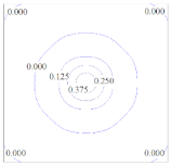
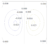
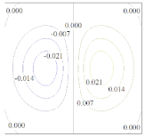
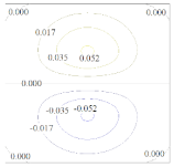
To investigate the characteristics of the four shape functions, Table 2 shows the contour plots of the shape functions of the four methods with the parameters in Table 1 and their first-order derivatives at the beam center point a (24, 0). It can be seen from Table 2 that the contour plots of the shape functions of the three interpolative meshless methods are completely consistent. They all meet the property of the Kronecker delta function and are significantly different from the contour maps of the MLS. The difference between the four methods is mainly reflected in the contour maps of the first-order derivatives of the shape functions, which may be the main reason for the difference in numerical accuracy of the three meshless interpolative methods.
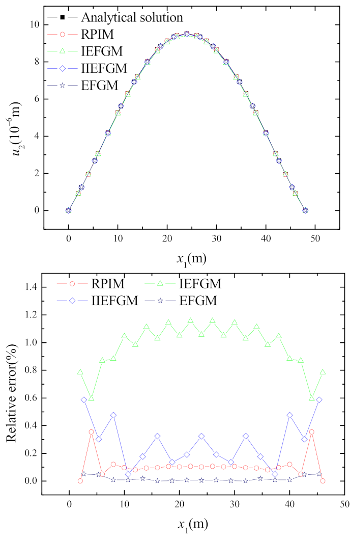
The nodal deflection u2 on the central axis x2 = 0 of the beam and the corresponding relative errors are shown and are compared in Figure 2. It is obvious that the meshless displacement results of the four methods agree very well with the analytical solutions, and all the relative errors are below 1.16%. However, the accuracy of the IEFGM is relatively lower than those of the other three meshless methods. The numerical solutions of EFGM and RPIM have better stability, and their maximum relative errors do not exceed 0.06% and 0.36%, respectively. The maximum relative error of the IIEFGM is also below 0.59%.
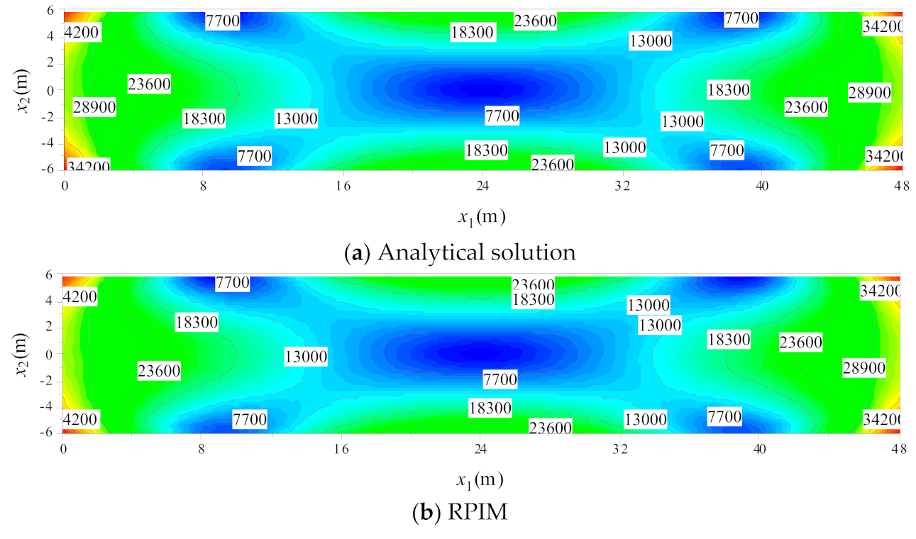
Figure 3 shows the numerical stress results of σ 22 on the central axis x2 = 0 of the beam and the relative errors. The EFGM with relative errors below 0.38% showed the best numerical accuracy over all the four meshless schemes for this example. For the RPIM, the accuracy near the two fixed ends with a maximum relative error of 3.73%, which is higher than the relative error of 1.32% at the middle span of the beam, is relatively poor. The maximum relative errors of the IEGM and the IIEFGM are 3.51% and 4.27%, respectively. Figure 4 shows the cloud diagram of the Von Mises stress on the problem domain for the analytical solution and the four meshless numerical results. The numerical solutions of the Von Mises stress obtained by the four meshless methods showed good agreement to the exact ones.

4.2. Cantilever Beam Subjected to a Uniform Load

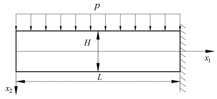
The orthotropic elastic cantilever beam shown in Figure 5 is considered in this example. Beam span l is 48 m, and depth h is 12 m. The upper boundary of the beam is subjected to a uniform load of q = 1000 N/m. The self-weight of the beam is ignored, and the structure is considered as in a plane stress state in the modelling.
The material coefficients of the beam are considered as s11 = 0.0799 × 10⁻¹⁰, s12 = −0.0375 × 10⁻¹⁰, s21 = −0.0375 × 10⁻¹⁰, s22 = 0.0798 × 10⁻¹⁰, and s66 = 0.2326 × 10⁻¹⁰. The analytical solutions of the displacements and the stresses of the beam are [35]
u 1 = 2 p x 1 x 2 3 ( s 12 + s 66 ) H 3 2 s 11 x 1 3 H 3 ( 9 s 12 3 s 66 ) x 1 10 H + ( 9 s 12 + 12 s 66 ) L 10 H 2 s 11 L 3 h 3 p x 2 + s 12 p ( L x 1 ) 2
u 2 = ( s 12 s 66 s 11 s 22 + 2 s 12 2 ) p x 2 4 2 s 11 H 3 s 12 x 1 2 H 2 + s 12 s 66 20 s 11 + s 12 2 10 s 11 s 22 4 3 p x 2 2 H s 22 p x 2 2 + p ( L x 1 ) 2 20 H 3 ( 10 s 11 x 1 2 + 20 s 11 L x 1 12 s 66 H 2 9 s 12 H 2 + 30 s 11 L 2 )
σ 1 = 6 q x 1 2 x 2 H 3 + 2 p 2 s 12 + s 66 4 s 11 ( 4 x 2 3 H 3 3 x 2 5 H )
σ 2 = p ( x 2 + H ) ( H 2 x 2 ) 2 2 H 3
τ 12 = 3 p x 1 ( 4 x 2 2 H 2 ) 2 H 3
As the geometry and the material in this example are similar to those in the example of Section 4.1, the trailed value range of the computing parameters in the meshless numerical modelling is chosen to be exactly the same as that in Section 4.1. Therefore, the optimal computing parameters for each meshless method are picked as the ones that get the lowest energy norm error among the tested value range and are listed in Table 3. The numerical results according to the optimal computing parameters in Table 3 are used for the comparison of the computational performance of the four meshless methods.
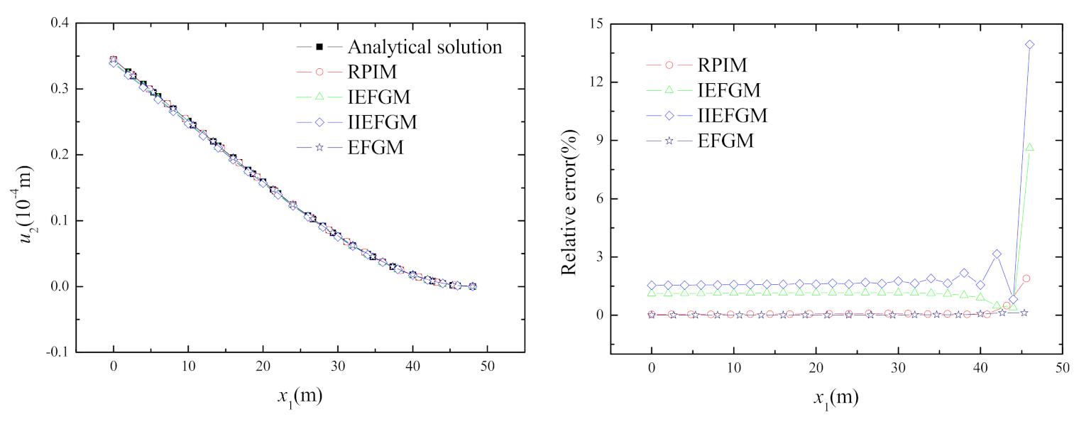
Since there is no special difference in the accuracy of curves in each direction, this paper only provides curves in a certain direction for illustration. The meshless solutions for the deflections of the nodes on the central axis of the beam x2 = 0 and the corresponding relative errors are presented in Figure 6. Generally, the numerical displacement results obtained by the four meshless methods show good accuracy and agree well with the exact solutions. The overall relative error values of RPIM, IEFGM and IIEFGM are about 0.07%, 1.1% and 1.6%, respectively, and the maximum relative error values are about 1.88%, 8.9% and 13.5%, respectively. The maximum relative error of EFGM is less than 0.27%. The relative errors of the three interpolative meshless methods, especially the IIEFGM and the IEFGM, show dramatic increase for the nodes at the fixed end of the beam.
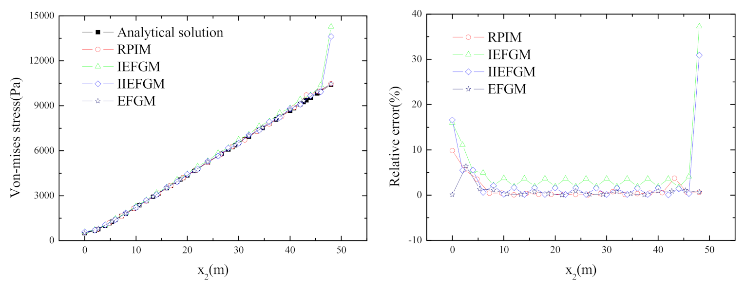
In Figure 7, the numerical results of the Von Mises stress for the nodes on the central axis of the beam are compared to the values calculated from the analytical stress solutions. The corresponding relative errors of the Von Mises stress results are also presented in this figure. Unlike the case of the displacement solutions, the Von Mises stress solutions of the IEFGM and the IIEFGM show obvious deviation from the corresponding analytical solution at the fixed end of the beam. Generally, the relative errors of Von Mises stress calculated by the four meshless methods are relative larger at the free end of the beam and gradually decrease and become stabilized towards the fixed end. Meanwhile, the IEFGM and the IIEFGM show much poorer accuracy with very large relative error near the fixed end of the beam. The EFGM has the highest accuracy, with a nodal relative error around 0.72% with a maximum of 6.4%. The nodal relative errors of the Von Mises stress solutions for the RPIM, the IEFGM and the IIEFGM are mostly around 0.4%, 3% and 1%, respectively. When x2 is between 10m and 40m, the variances of the RPIM, EFGM, IEFGM and IIEFGM are 0.0425, 0.1129, 0.797 and 0.546 respectively. Therefore, the Von Mises stress solutions of the RPIM are more accurate and stable than those of the other two interpolative approaches in this case.

4.3. Ring under Pressures Applied Both Internally and Externally

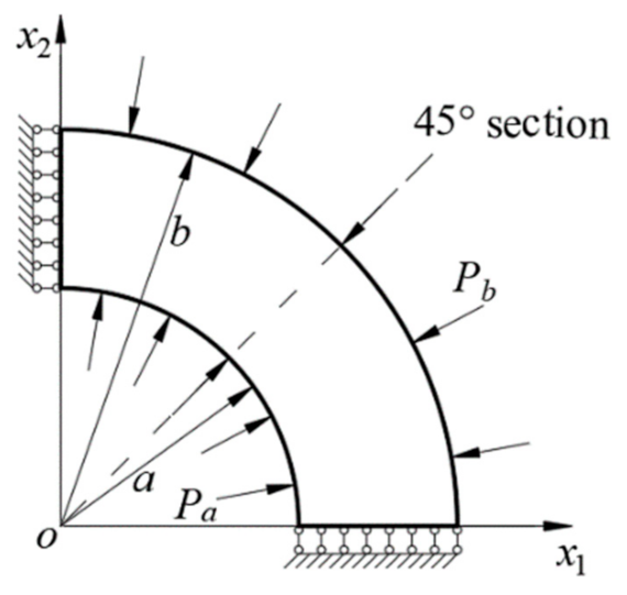
To consider an orthotropic elastic ring under both internal and external compression, as shown in Figure 8, only one quarter of the structure needs to be modeled by symmetry. The inner and outer diameters of the ring are a = 12 m and b = 20 m, respectively. The pressures of Pa = 100 Pa and Pb = 300 Pa are applied both internally and externally. The numerical example is considered as in a plane stress state.
The ring is circular orthotropic, and the anisotropic pole is located at the center of the ring. The material compliance coefficients in a polar coordinate system are s11 = 0.0799 × 10⁻⁴, s12 = −0.0375 × 10⁻⁴, s21 = −0.0375 × 10⁻⁴, s22 = 0.0798 × 10⁻⁴ and s66 = 0.2326 × 10⁻⁴. The exact solutions of the radial displacement and the stresses are written as follows [35]:
u r = b E θ ( 1 c 2 k ) ( P a c k + 1 P b ) ( k v θ ) ( r b ) k + ( P a P b c k 1 ) c k + 1 ( k + v θ ) ( b r ) k
σ r = P a c k + 1 P b 1 c 2 k ( r b ) k 1 P a P b c k 1 1 c 2 k c k + 1 ( b r ) k + 1
σ θ = P a c k + 1 P b 1 c 2 k k ( r b ) k 1 + P a P b c k 1 1 c 2 k k c k + 1 ( b r ) k + 1
where c = a / b , k = s 11 / s 22 , E θ = 1 / s 22 , v θ = s 12 / s 22 .
In order to effectively compare the accuracy of the four meshless methods with completely different computing parameter groups, the following appropriate ranges are also selected for several kinds of the computational parameters in this example: for a uniform mesh of the nodes, the number of nodes in the radial direction n1 = (7, 9, 11, 13), the number of nodes in the circular direction n2 = (19, 21, 23, 25); for a fixed uniform mesh of l1 × l2 = 6 × 24 for the background cells of the Gauss quadrature, the dimensionless factors for scaling the influence domain dmax = (1.5, 2.5, 3.5), q = (−0.5, 0.5, 1.5, 2.5) and c = (1.0, 3.0, 5.0); for the MQ radial basis in the RPIM, the singular weight parameter α = (4, 6, 8, 10) for the IEFGM, and the penalty factor β = 3 × 10¹⁴ for the EFGM to enforce displacement boundary conditions. Apparently, all 48, 576, 192 and 48 groups of the computing parameters need to be tested for the EFGM, the RPIM, the IEFGM and the IIEFGM, respectively, to determine the optimal settings for each method with regard to the relatively lower energy norm error. The corresponding optimal sections of the parameters for the four meshless schemes are presented in Table 4.
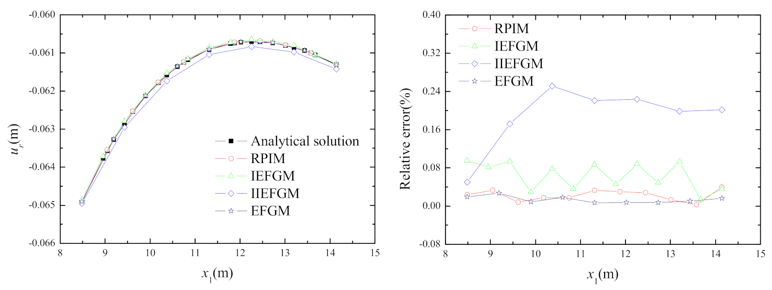
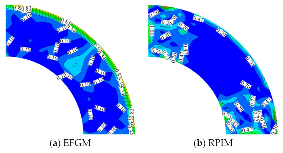
The nodal solutions of the radial displacement at section θ = 45° of the ring with the values of parameters in Table 4, the variances of the nodal relative errors in Table 5 and the relative errors are shown in Figure 9. It is obvious that the displacement results of the four meshless approaches are in generally good agreement with the analytical ones. The accuracy of the RPIM and the EFGM are almost the same and are higher and more stable than the other two methods. The maximum values of the nodal relative errors for the RPIM, IEFGM and the IIEFGM are about 0.0398%, 0.09% and 0.24%, respectively. The variances of the nodal relative errors for the RPIM, EFGM, IEFGM and the IIEFGM are about 0.0001, 0.000005, 0.00085 and 0.0043, respectively. The contour plots for the relative errors of the Von Mises stress obtained by the four meshless methods are presented in Figure 10. It could be found that the four meshless approaches can get good results of the Von Mises stress for this example, while the accuracy of each method in the different areas of the problem domain is not the same.

5. Conclusions

In this study, the RPIM, the IEFGM and the IIEFGM are applied to solve orthotropic elastic problems. The essential/displacement boundary conditions are applied by the direct method to calculate and analyze orthotropic clamped-clamped beams, orthotropic cantilever beams and orthotropic rings subjected to uniform loads. Since the principles and computing parameters of these three interpolative methods are very different, this paper uses the numerical solution with the optimal parameter group corresponding to the minimum energy norm error within a certain trailed range of each method to compare their accuracy. For example in Section 4.1, the maximum relative error of σ 22 is 3.73%, which is higher than the relative error of 1.32% in the middle of the beam span. However, the maximum relative errors of the IEGM and the IIEFGM are 3.51% and 4.27%, respectively. For example in Section 4.2, the overall relative error values of nodal deformation for RPIM, IEFGM and IIEFGM are about 0.07%, 1.1% and 1.6%, respectively, and the maximum relative error values are about 1.88%, 8.9% and 13.5%, respectively. For example in Section 4.3, the accuracy of radial displacement for the RPIM and the EFGM are almost the same and are higher and more stable than the other two methods. The maximum values of the nodal relative errors for the RPIM, IEFGM and the IIEFGM are about 0.0398%, 0.09% and 0.24%, respectively. The results show that the three meshless interpolation methods have better numerical accuracy in the modeling of orthotropic elastic problems, and the radial point interpolation method (RPIM) has the highest accuracy. The research results of this paper can provide a certain reference value for future research on the selection of meshless form functions in interpolation. It is one of the regrets of this paper that the differences in numerical efficiency of these methods cannot be effectively investigated at the same time.

Author Contributions

Conceptualization, methodology, supervision, and funding acquisition, D.M.L.; investigation, validation, visualization and writing—original draft preparation, Y.-Y.Z. and Y.-C.T.; writing—review and editing, D.M.L., X.-B.L. and B.L.; Y.-Y.Z. and Y.-C.T. contributed equally to this work. All authors have read and agreed to the published version of the manuscript.

Funding

This work was supported by the National Natural Science Foundation of China (12002247), the Natural Science Foundation of Hubei Province (2018CFB129), Fundamental Research Funds for the Central Universities of China (WUT: 2016IVA022 and WUT: 20271IVB013) and the National innovation and entrepreneurship training program for college students of China (202210497088).

Data Availability Statement

Data will be made available on request.

Conflicts of Interest

The authors declare no conflict of interest.

References

  1. Belytschko, T.; Lu, Y.Y.; Gu, L. Element-free Galerkin methods. Int. J. Numer. Methods Eng. 2010, 37, 229–256. [Google Scholar] [CrossRef]
  2. Liu, W.K.; Jun, S.; Zhang, Y.F. Reproducing kernel particle methods. Int. J. Numer. Methods Fluids 1995, 20, 1081–1106. [Google Scholar] [CrossRef]
  3. Li, D.M.; Featherston, C.A.; Wu, Z.M. An element-free study of variable stiffness composite plates with cutouts for enhanced buckling and post-buckling performance. Comput. Methods Appl. Mech. Eng. 2020, 371, 113314. [Google Scholar] [CrossRef]
  4. Li, D.M.; Kong, L.H.; Liu, J.H. A generalized decoupling numerical framework for polymeric gels and its element-free implementation. Int. J. Numer. Methods Eng. 2020, 121, 2701–2726. [Google Scholar] [CrossRef]
  5. Chen, J.S.; Pan, C.H.; Wu, C.T.; Liu, W.K. Reproducing Kernel Particle Methods for large deformation analysis of non-linear structures. Comput. Methods Appl. Mech. Eng. 1996, 139, 195–227. [Google Scholar] [CrossRef]
  6. Li, D.M.; Tian, L.R. Large deformation analysis of gel using the complex variable element-free Galerkin method. Appl. Math. Model. 2018, 61, 484–497. [Google Scholar] [CrossRef]
  7. Li, D.M.; Liu, J.H.; Nie, F.H.; Featherston, C.A.; Wu, Z.M. On tracking arbitrary crack path with complex variable meshless methods. Comput. Methods Appl. Mech. Eng. 2022, 399, 115402. [Google Scholar] [CrossRef]
  8. Pan, J.H.; Li, D.M.; Luo, X.B.; Zhu, W. An enriched improved complex variable element-free Galerkin method for efficient fracture analysis of orthotropic materials. Theor. Appl. Fract. Mech. 2022, 121, 103488. [Google Scholar] [CrossRef]
  9. Liew, K.M.; Sun, Y.Z.; Kitipornchai, S. Boundary element-free method for fracture analysis of 2-D anisotropic piezoelectric solids. Int. J. Numer. Methods Eng. 2007, 69, 729–749. [Google Scholar] [CrossRef] [Green Version]
  10. Rabczuk, T.; Belytschko, T. Cracking particles: A simplified meshfree method for arbitrary evolving cracks. Int. J. Numer. Methods Eng. 2004, 61, 2316–2343. [Google Scholar] [CrossRef]
  11. Liu, G.R.; Gu, Y.T. A point interpolation method for two-dimensional solids. Int. J. Numer. Methods Eng. 2001, 50, 937–951. [Google Scholar] [CrossRef]
  12. Wang, J.G.; Liu, G.R. A point interpolation meshless method based on radial basis function. Int. J. Numer. Methods Eng. 2002, 54, 1623–1648. [Google Scholar] [CrossRef]
  13. Ren, H.P.; Cheng, Y.M. The interpolating element-free Galerkin method for two-dimensional elasticity problems. Int. J. Appl. Mech. 2011, 3, 735–758. [Google Scholar] [CrossRef]
  14. Lancaster, P.; Salkauskas, K. Surface generated by moving least squares methods. Math. Comput. 1981, 37, 141–158. [Google Scholar] [CrossRef]
  15. Wang, J.F.; Sun, F.X.; Cheng, Y.M. An improved interpolating element-free Galerkin method with a nonsingular weight function for two-dimensional potential problems. Chin. Phys. B 2012, 21, 090204. [Google Scholar] [CrossRef]
  16. Deng, Y.J.; He, X.Q. An improved interpolating complex variable meshless method for bending problem of Kirchhoff plates. Int. J. Appl. Mech. 2017, 9, 1750089. [Google Scholar] [CrossRef]
  17. Zhang, T.; Li, X.L. A variational multiscale interpolating element-free Galerkin method for convection-diffusion and Stokes problems. Eng. Anal. Bound. Elem. 2017, 82, 185–193. [Google Scholar] [CrossRef]
  18. Wang, Q.; Zhou, W.; Feng, Y.T.; Ma, G.; Cheng, Y.G.; Chang, X.L. An adaptive orthogonal improved interpolating moving least-square method and a new boundary element-free method. Appl. Math. Comput. 2019, 353, 347–370. [Google Scholar] [CrossRef]
  19. Singh, R.; Singh, K.M. Interpolating meshless local Petrov-Galerkin method for steady state heat conduction problem. Eng. Anal. Bound. Elem. 2019, 101, 56–66. [Google Scholar] [CrossRef]
  20. Bourantas, G.; Zwick, B.F.; Joldes, G.R.; Wittek, A.; Miller, K. Simple and robust element-free Galerkin method with almost interpolating shape functions for finite deformation elasticity. Appl. Math. Model. 2021, 96, 284–303. [Google Scholar] [CrossRef]
  21. Wang, L.; Qian, Z. A meshfree stabilized collocation method (SCM) based on reproducing kernel approximation. Comput. Methods Appl. Mech. Eng. 2020, 371, 113303. [Google Scholar] [CrossRef]
  22. Wang, L.; Liu, Y.; Zou, Y.; Yang, F. A gradient reproducing kernel based stabilized collocation method for the static and dynamic problems of thin elastic beams and plates. Comput. Mech. 2021, 68, 709–739. [Google Scholar] [CrossRef]
  23. Qian, Z.; Wang, L.; Gu, Y.; Zhang, C. An efficient meshfree gradient smoothing collocation method (GSCM) using reproducing kernel approximation. Comput. Methods Appl. Mech. Eng. 2021, 374, 113573. [Google Scholar] [CrossRef]
  24. Quintero MA, M.; Tam CP, T.; Li, H.T. Structural analysis of a Guadua bamboo bridge in Colombia. Sustain. Struct. 2022, 2, 000020. [Google Scholar]
  25. Ponzo, F.C.; Antonio, D.C.; Nicla, L.; Nigro, D. Experimental estimation of energy dissipated by multistorey post-tensioned timber framed buildings with anti-seismic dissipative devices. Sustain. Struct. 2021, 1, 000007. [Google Scholar]
  26. Liew, K.M.; Lei, Z.X.; Yu, J.L.; Zhang, L.W. Postbuckling of carbon nanotube-reinforced functionally graded cylindrical panels under axial compression using a meshless approach. Comput. Methods Appl. Mech. Eng. 2014, 268, 1–17. [Google Scholar] [CrossRef]
  27. Wu, Z.M.; Raju, G.; Weaver, P.M. Optimization of postbuckling behaviour of variable thickness composite panels with Variable Angle Tows: Towards 'buckle-free' design concept. Int. J. Solids Struct. 2018, 132–133, 66–79. [Google Scholar] [CrossRef]
  28. Dinis LM, J.S.; Jorge RM, N.; Belinha, J. A 3D shell-like approach using a natural neighbour meshless method: Isotropic and orthotropic thin structures. Compos. Struct. 2010, 92, 1132–1142. [Google Scholar] [CrossRef]
  29. Njiwa, R.K. Isotropic-BEM coupled with a local point interpolation method for the solution of 3D-anisotropic elasticity problems. Eng. Anal. Bound. Elem. 2011, 35, 611–615. [Google Scholar] [CrossRef]
  30. Bui, T.Q.; Nguyen, M.N. A novel meshfree model for buckling and vibration analysis of rectangular orthotropic plates. Struct. Eng. Mech. 2011, 39, 579–598. [Google Scholar] [CrossRef]
  31. Fallah, N.; Nikrafter, N. Meshless finite volume method for the analysis of fracture problems in orthotropic media. Eng. Fract. Mech. 2018, 204, 46–62. [Google Scholar] [CrossRef]
  32. Lohit, S.K.; Gaonkar, A.K.; Gotkhindi, T.P. Interpolating Modified Moving Least Squares based element free Galerkin method for fracture mechanics problems. Theor. Appl. Fract. Mech. 2022, 122, 103569. [Google Scholar] [CrossRef]
  33. Luo, X.B.; Li, D.M.; Liu, C.L.; Pan, J.H. Buckling analysis of variable stiffness composite plates with elliptical cutouts using an efficient RPIM based on naturally stabilized nodal integration scheme. Compos. Struct. 2022, 302, 116243. [Google Scholar] [CrossRef]
  34. Hardy, R.L. Theory and applications of the multiquadrics-Biharmonic method (20 years of discovery 1968–1988). Comput. Math. Appl. 1990, 19, 163–208. [Google Scholar] [CrossRef] [Green Version]
  35. Lekhnit︠s︡kii, S.G. Anisotropic Plates; Gordon and Breach: Philadelphia, PA, USA, 1968. [Google Scholar]
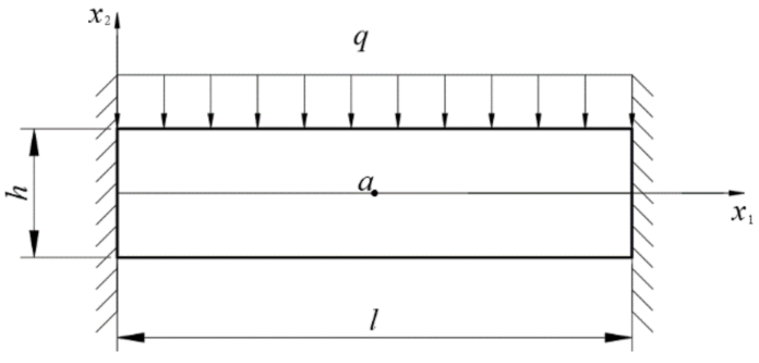
Figure 1. Clamped-clamped beam subjected to uniform load.
Buildings 13 00387 g001
Figure 2. Deflection u2 and its relative error at x2 = 0 m.
Buildings 13 00387 g002
Figure 3. Stress σ 22 and its relative error at x2 = 0 m.
Buildings 13 00387 g003
Figure 4. Contour of the Von Mises stress of the clamped-clamped beam.
Buildings 13 00387 g004aBuildings 13 00387 g004b
Figure 5. Cantilever beam under uniform load at its upper boundary.
Buildings 13 00387 g005
Figure 6. The nodes deflection and its relative error at central axis.
Buildings 13 00387 g006
Figure 7. Solutions of the Von Mises stress and the relative error at x2 = 0.
Buildings 13 00387 g007
Figure 8. A quarter of the ring.
Buildings 13 00387 g008
Figure 9. Radial displacement ur and relative error at θ = 45° of the ring.
Buildings 13 00387 g009
Figure 10. Contour plots of the relative error for the Von Mises stress.
Buildings 13 00387 g010aBuildings 13 00387 g010b
Table 1. Optimal computing parameters of each method within the tested range.
n1 × n2l1 × l2dmaxOthers
EFGM19 × 1112 × 83.5 β = 3 × 10¹⁴
RPIM25 × 1112 × 84.5q = 2.5, c = 1.0
IEFGM25 × 1312 × 82.5 α = 6.0
IIEFGM19 × 1312 × 81.5
Table 2. Contour plot of the shape functions and their 1st order derivate at point (24, 0) by four different methods.
MLSRPIMIMLSIIMLS
Φ Buildings 13 00387 i001Buildings 13 00387 i002Buildings 13 00387 i003Buildings 13 00387 i004
Φ , x Buildings 13 00387 i005Buildings 13 00387 i006Buildings 13 00387 i007Buildings 13 00387 i008
Φ , y Buildings 13 00387 i009Buildings 13 00387 i010Buildings 13 00387 i011Buildings 13 00387 i012
Table 3. Optimal value of computing parameters in this example.
n1 × n2l1 × l2dmaxOther Parameters
EFGM19 × 1312 × 83.5 β = 3 × 10¹⁴
RPIM21 × 712 × 84.5q = 2.5, c = 1.0
IEFGM25 × 1312 × 81.5 α = 6.0
IIEFGM25 × 1312 × 81.5
Table 4. Optimal parameters each method within the tested range.
n1 × n2l1 × l2dmaxOther Parameters
EFGM9 × 256 × 242.5 β = 2 × 10⁸
RPIM11 × 256 × 243.5q = 1.5, c = 1.0
IEFGM13 × 256 × 241.5 α = 4.0
IIEFGM7 × 256 × 241.5
Table 5. The variances of the relative errors.
EFGMRPIMIEFGMIIEFGM
Radial displacement0.00010.0000050.000850.0043
Von Mises stress0.072250.05450.3910.9947
Disclaimer/Publisher’s Note: The statements, opinions and data contained in all publications are solely those of the individual author(s) and contributor(s) and not of MDPI and/or the editor(s). MDPI and/or the editor(s) disclaim responsibility for any injury to people or property resulting from any ideas, methods, instructions or products referred to in the content.