1. Introduction
Three-dimensional (3D) printing (or Additive Manufacturing, AM) offers geometric freedom of shapes and the possibility of saving significant amounts of materials [
1]. AM processes have only slowly found their way into the construction industry compared to other sectors. This can be attributed to the larger scale of the components [
2] and the fact that they are hardly ever produced in series. On the other hand, there is only a limited selection of materials available whose processability is suitable for automated manufacturing systems [
3]. In addition, the approaches to planning and production are only conditionally oriented towards automation [
4].
Before the introduction of AM, the desire for architectural freedom often conflicted with the economic requirements of a high degree of automation [
5,
6]. Steel construction, for example, is extraordinarily well suited for use in freely shaped load-bearing structures due to its material properties. However, due to a limited range of profile shapes and conventional construction methods, the freedom in terms of design potential is limited [
6]. The use of automated manufacturing processes would increase the potential of design possibilities enormously.
As a basis for considerations regarding new production methods or material-specific innovations, lessons learned from the historical development of building construction can be compared with how new technologies are handled today. Particularly for iron and later steel, design procedures were reformed to fit the specific material and fabrication methods [
7].
Generally, the paper is structured around the material- and process-specific aspects of stiffeners’ design for fixed definitions of load cases, followed by proposed geometries and their fabrication. A step between geometry generation and its fabrication is included, hereafter referred to as a feasibility analysis, composed of test trials and fabrication path adjustment, focused on characteristic strengthening application with bounded build volume (
Figure 1).
In the early beginnings of the iron/steel construction era, structures were built using construction techniques proven effective for previously used building materials. The structural principles of the construction followed that of a stone, e.g., bridges were designed as an arch, continuing compressed stone arch heritage (Coalbrookdale bridge, also known as “Iron Bridge”). Steel connection design was concurrently replicated from traditional timber construction with the use of bolts and wedges [
8,
9]. The materially inadequate design was also reflected in the reproduction of bridge design procedures onto a multistory building (e.g., Jules Saulnier’s chocolate mill, 1872), where the diagonal bracing of the structure strongly resembled that of the timber truss [
8,
10]. A more material-specific (in the context of iron and steel) design was introduced by Hector Guimard, which he built on the idea of Violett-le-Duc, in the example of École du Sacré-Coeur [
8,
11]. Eventually, the steel construction industry redefined the focus on mass production; starting from Joseph Paxton’s Crystal Palace (1851), the concepts of prefabrication, modularity and standardization [
10,
11] became famous for the first time. The development of the prefabrication of components not only affected economic efficiency but also influenced the shape of the structures [
10], resulting in increased production of standardized rolled sections [
9].
In complete contrast to the contemporary rolled, standardized sections is the process of 3D printing in steel construction using wire-and-arc additive manufacturing (WAAM). This technology is a Directed Energy Deposition (DED) arc-type process that allows the fabrication of steel components with more geometrical freedom while maintaining good mechanical properties [
12]. Moreover, it is the metal AM process most suitable for adoption for large-scale components characteristic for the construction industry, as it has few limitations in the shape and size of the printed object [
13]. First explorations on WAAM for construction have been studied over the recent years [
14,
15]. Benefits of AM for construction, to name a few, are primarily customization, the potential of reducing construction time, human error and material consumption, and lastly, the potential contribution to structural strengthening and repair [
1,
16].
Concerning WAAM fabrication, a wavy surface structure is created by layering the single welding sheets on top of each other. The product’s shape is thus much more firmly linked to the production than with other processes. An important characteristic of the WAAM manufacturing process is that the substrate is monolithically connected to the manufactured object. Subsequent separation of the substrate and the AM object can be extremely time-consuming, laborious, and in the worst case, can damage the printed object. It is therefore suitable to plan the design of the object in such way that the substrate is part of the geometry itself. Reasoning can be further expanded to print directly onto semi-finished components for their adjustment, enhancement, strengthening or similar cases.
Lange et al. in [
14] have researched strengthening where the focus was on the design boundary conditions, production and experimental load capacity tests of stiffeners for strengthening. Potential benefits in terms of material saving were discussed. In addition, the first test showed that the load capacity of WAAM-produced stiffeners was comparable to those that were conventionally produced [
14].
The focus of this paper is to discuss the potential for using the WAAM process to add ribs as the stiffeners to semi-finished products (steel profiles). The main focus is on ways to enhance the web of an I-section. Specifically, the welding of ribs in areas of local load introduction will be investigated. In addition, considerations will be made as to how a flexural beam can be strengthened in areas of increased moment loading. Here, the investigations relate to the flange. For a meaningful application of the technology, a fundamental prerequisite is that the semi-finished products still comply with the profile tolerances after applying the reinforcing structures concerning the deformations caused by the high heat input from the welding process. To this end, different strategies for the sequence of application of the individual layers were tried out. Therefore, the investigations focus on the deformations of the semi-finished products during and after welding. The aim is also to develop strategies for using the process efficiently and in a way that satisfies architectural requirements. For this purpose, research is to be carried out in advance to understand better the material in its production and design development context.
2. Experimental Setup
2.1. Wire-and-Arc Additive Manufacturing (WAAM) Process
Three main methods for metal additive manufacturing are Powder Bed Fusion (PBF), Direct Energy Deposition (DED) and Sheet Lamination. WAAM is a subset of DED processes, where an electric arc is used as the heat source for melting metallic wire, i.e., the feed material [
1]. Path guidance is provided by either a robotic system or a computer-controlled gantry [
17]. In the welding process, melted wire is emitted into the molten pool utilizing droplets. Geometry is built up incrementally, layer-by-layer, or dot-by-dot [
6]. The process is characterized by comparatively high assembly rates and low material costs [
1,
17]. Metal inert gas welding (MIG) is usually the method of choice for WAAM production due to the higher level of control over the wire coming directly out of the welding torch as a consumable electrode. Cold Metal Transfer (CMT) welding is a modified version of the MIG process [
17]. The wire is introduced and detected by the system. The system detects the start of the short-circuit phase; after that, the current is specifically throttled. As a result, the material transition is almost without spattering. Subsequently, the wire is retracted again, which facilitates the detachment of the drops of molten wire [
18]. This process is repeated again and again. Depending on use, this can happen up to 90 times per second. Due to the mechanical detection of the arc length, the process also remains stable independent of the surface condition of the substrate [
18]. Another advantage of the process is the significantly low heat input compared to conventional continuous welding processes. Due to the constant interruptions of the arc, thermal energy is only briefly introduced into the workpiece [
18].
2.2. The Adopted Experimental Setup
The experimental setup comprises from a perforated welding table, and a fully automatic power source (Fronius Tps 600i, Fronius International GmbH) used for the CMT welding and a robot (UR16e cobot, from Jugard and Küstner). The feed wire is a copper-coated solid wire with increased manganese content specific for semi-automatic welding with a diameter of 1.2 mm (SupraMig Ultra, LincolnElectronics). The wire consists of manganese, silicon and carbon. The shielding gas is Sagox 18, a gas mixture of 82% argon and 18% carbon dioxide. Steel plates (S 235) with a thickness of 20 mm were used for the preliminary tests. The base for the investigations and the fabrication of the demonstrators were IPE 200 profile pieces (S 235 JR+AR) with a length of 20 cm each. In total, 10 (ten) IPE 200 profile pieces were used, out of which half was planned for the fabrication feasibility analysis and the other half for the final demonstrators, as presented later in the paper. The setup heavily relies on the already existing infrastructure of the Digital Building Fabrication Lab (DBFL) at TU Braunschweig and is part of its communication network. Path planning and control are carried out with Grasshopper3D-adapted plug-in Robots for Rhino 7. The start-stop control of the welding system is made possible by a digital signal. The signal is sent from the UR16e to the Beckhoff of the DBFL, which is connected to the control unit of the welding system to start or stop the welding process. Setup is then operative through the described signal processing, schematically presented in
Figure 2a. Setup mid-process is shown in
Figure 2b.
2.3. Process Parameter Definition and Test Trials for Simple Geometries
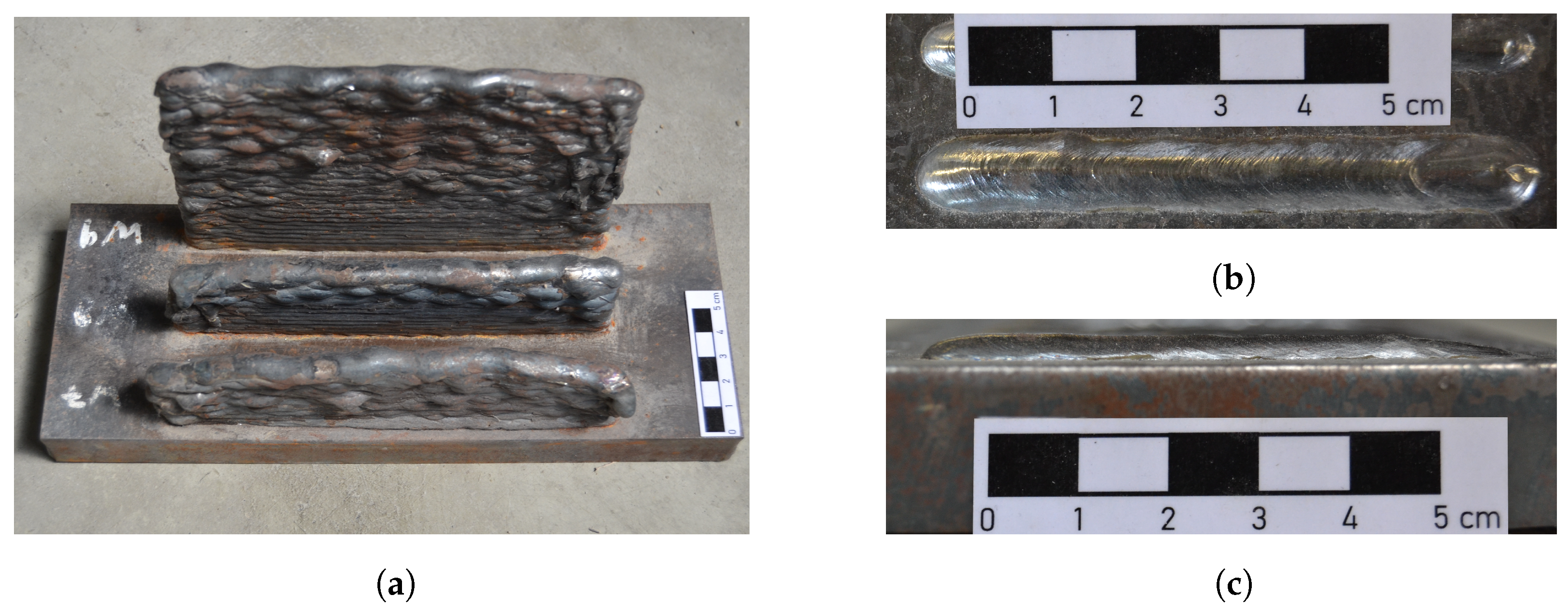
Preliminary geometries were produced in the first series of experiments to know the process and the material, along with learning their characteristics and behaviour. The first bodies produced were limited to gradually building higher and higher walls. It was easy to observe how the surface quality decreases with decreasing heat dissipation. During these tests, sufficient heat dissipation became the main problem during production,
Figure 3a. In addition, by comparing the actual heights with the digital models from the path planning, it was possible to calculate initial values for the height of the individual layers.
Process parameters are established through several iterations of test trials to reach the final, optimum ones that ensure stable welding for all. Accordingly, a wire feed speed of WFS = 4 m/min, a voltage of I = 142 A, a current of U = 14.5 V, and a gas flow of GF = 12 L/min are the selected values for the whole duration of the experiment.
Another important point for a uniform construction of multi-layer geometries is the knowledge of the geometry of the individual layers. In the first experiments, it already turned out that the geometry of the individual welds varied at the beginning and end.
Figure 3b,c present a single weld applied from left to right.
It can be seen that at the end of the seam, the weld bed forms under gas pressure. At this point, the layer height drops noticeably. When several layers are stacked on top of each other, such an unevenness quickly accumulates to large deviations from the target geometry. A simple solution is to print each layer with an alternating direction of travel. This way, the error is distributed evenly on both sides. A welding duration extension is also introduced to the path at the line ends. Additional material is applied, and thus the error is also compensated for to some extent.
A series of tests were carried out in order to be able to produce the thinnest possible walls with the chosen welding parameters. The size of the cross-section of a layer results from the amount of deposited material per unit length. This results from the ratio of the wire feed speed (WFS) and the travel speed (TS) [
19]. The welding parameters, which include the wire feed, were determined uniformly for the experiments within the present work scope. Thus, the layer geometry can only be influenced by varying the travel speed. The aim is to create a path that is as narrow as possible but still uniform.
For this purpose, tracks with different speeds were welded in the first series of tests. In
Figure 4a, the speeds are shown from 300 mm/min (track 1) in ascending steps of 300 mm/min up to 2100 mm/min (track 7).
It is easy to see that the individual lines become thinner and thinner as the speed increases. Apart from the first web, however, the change in the height of the webs is only very slight. In this case, however, the height is negligible for the time being, as the layer height can be flexibly taken into account later when slicing the geometries to be printed.
When looking at the tracks of
Figure 4a, tracks 2–4 with a speed range of 600 to 1200 mm/min turned out to be the most suitable. Line 1 still appears to be too wide, whereas the height of lines 5–7 shows increased discontinuities. A noticeable imbalance between wire feed and travel speed can probably explain these occurrences.
In another series, tracks with different speeds were tested again. This time, the speed was only increased by 100 mm/min. The tested speeds were between 600 and 1000 mm/min. In addition, a wall consisting of 10 layers built on top of each other was produced in each case to determine the layer quality’s behaviour in layered form. The results are shown in
Figure 4b.
Lines 1 to 5 are made in one layer from left to right with increasing speed, and lines 6 to 10 are the associated 10-layer walls. These are also arranged in ascending speed. The surface quality of the single-layer samples is excellent at all speeds. In the multi-layer specimens, however, slight unevenness results at speeds above 800 mm/min (No. 9 and 10). For further tests, the speed was chosen, resulting in the thinnest possible wall with a quality that remained stable, in this case, web three or wall eight at a speed of 800 mm/min. The resulting wall thickness is approximately 6 mm.
The layer height is mentioned in various further publications. The height of a single layer is approximately 1–2 mm [
17,
20,
21,
22]. Following these recommendations, the exact layer height for the given process parameters was obtained during the first tests for printing walls. By measuring the actual height after manufacturing and comparing it with the printed number of layers, the value for the following experiments was set to 1.6 mm.
3. Design Exploration Study on WAAM Stiffeners for I-Beam
There is no standardized design procedure for WAAM [
23]. The following section discusses possibilities for the design for local strengthening of steel beams. Special attention was paid to the load application area. With an example of the stiffeners, design possibilities were illustrated on how geometry could be adapted to the manufacturing process and the static or constructive benefit. For this purpose, two different design approaches were developed based on literature research and an analysis of the load-bearing behaviour of stiffeners. In each case, the case of a whole rib and a partial rib were considered. In addition, an approach for local strengthening in areas of increased bending stress was developed.
3.1. Reinforcements for Standardized Steel Beams
In traditional steel construction, structural elements are often calculated using theoretical simplifications that reduce the complex three-dimensional behaviour into one- or two-dimensional models. However, since this is an idealization, certain areas must be considered separately (for example, disturbed regions). These are local areas where loads are introduced, or forces have to be diverted due to geometric boundary conditions of the components [
24]. High local stresses arise at these points. Even components not loaded according to the internal forces can exceed the material strength at specific points. At these points, stiffeners or ribs are used to strengthen the structural elements. However, stiffeners can also be necessary for various other reasons. These include, for example, stabilizing the cross-sectional shape in the case of torsion, as well as preventing the risk of local buckling in the case of tall components [
24].
There are already solutions for the fully automatic processing of semi-finished products in steel construction, in which the beams are scanned, and then a robot stops the finished sheets. At the same time, they are welded on by another robot. The production of classic stiffeners using WAAM does not seem competitive for the time being. However, a closer look at the production chain makes things easier. Since sheet metal parts are no longer needed, they do not have to be procured, cut and stored. In addition, there is no waste. Furthermore, the need for robots is reduced as the work step of stopping is eliminated [
25].
For a promising approach, however, the focus is also on the ratio of material used versus structural performance and additional design advantages. For example, the clearance between the flanges can be maintained by individually adapting the stiffener geometry, and the area can be used for laying cables. The possible flexible application of material by the robot opens up new geometric possibilities for targeted and function-related use of the material. For example, ribs can be dimensioned and designed differently according to the magnitude of the respective local load so that the reinforcements can be adapted minimally invasively.
Another possible application for the reinforcement of semi-finished products with the help of the WAAM process is the increase in the load-bearing capacity of beams in the area of increased moment loads. In construction situations where a larger profile is to be avoided for constructional or economic reasons, the profile used can be strengthened in the areas with too high a load by applying additional material. Another possible application is the subsequent reinforcement of already installed beams in existing buildings, which have to be strengthened in places or strengthened for higher loads due to changes in use.
3.2. Design Conditions
When high compressive forces are applied, the web plate can fail in the area where the force is applied.
Figure 5 shows the different failure mechanisms dealt with in the standard. The local failure of the web can be divided into three categories: a—plastic failure (compression, stretching); b—local buckling (crippling); or c—buckling of the web plate over a larger area of the web height. Furthermore, a distinction is made between force introduction (cases a and b) and force transmission (case c) [
24]. As a fourth failure mode, the flange’s bending is also considered.
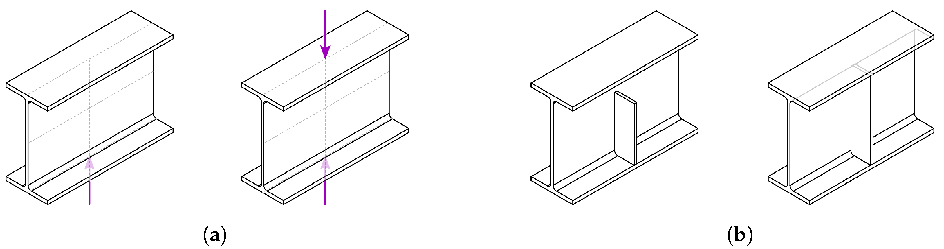
The ideas of the computational approaches of the developed geometries were based on the possible failure mechanisms and current verification methods from the standard, which are explained in the following sections. Two concrete load case situations were selected for this purpose. A single-acting load and a load acting from both sides, from above and from below, were treated. The treated load cases and the related conventional construction solutions are shown in
Figure 6. Since this work focuses on the feasibility and fabrication of the ribs, geometries do not exhibit a precision of specific pre-calculated structural elements, but rather a potential, conceptually derived shape.
3.3. Approach via Material Reduction
The load-bearing behaviour of stiffeners works by transferring the external load into the sheet stiffener. The load is then transferred into the web along the length via the weld seam along the web edge. The eccentricity between the plate and the web creates an offset moment. This is transferred via the connection to the upper and lower flanges.
Figure 7a illustrates the equilibrium of forces for the design. The special feature of partial stiffeners is that no horizontal force pair can be formed due to the missing connection to the second flange. Therefore, the resulting moment is transferred via bending, and the weld to the web is also loaded vertically [
24],
Figure 7b.
For the design of the stiffener geometries, the shear-resistant connection to the web and the flanges plays a particularly important role. In these areas, a suitable bond with the steel profile is essential. Sufficient material should be arranged in these areas in particular. In the outer areas, as well as the free corner of the partial rib, on the other hand, the material can be saved without permanently impairing the load-bearing capacity.
The first approach refers to pure material reduction, whereby the steel stiffener’s original concept and mode of action are unchanged. The failure case of buckling of the web perpendicular to the plate line was used as a reference. In order to model the instability (buckling) issue, an upright single-span beam can be assumed. The geometry of the stiffeners is oriented to the moment line of the corresponding deformation figure: partial and full stiffeners,
Figure 8.
3.4. Approach through Optimized Load Application
Areas of concentrated load application require additional verification during the design stage. If the design outcome provides unverified results (according to the standards applied), disturbed areas will be observed separately and enhanced with stiffeners, increasing the structural strength at reasonable economic and environmental costs. Verification methods for calculating the necessity of stiffener plates in the disturbed areas are presented in [
26]. For the verification, DIN EN 1993-5 section 6, “Stressability with transverse pressure”, and DIN EN 1993-8 section 6.2.6.2, “Support web with stress ability with transverse pressure” are available.
An essential factor in dimensioning the maximum force that can be introduced into the web is the effective load propagation length [
26]. This results, on the one hand, from the area over which the force is introduced into the profile. In addition, it spreads over the flange thickness and fillet height,
Figure 9a. In the old standard, an angular ratio of 1:2.5 was suggested in some cases, but the usual load spread angle is 45° [
24]. Therefore, the critical point is that the cross-section only results in the web plate with the effective load propagation length.
When considering the verification procedure for local load application without stiffeners, the effective load propagation length leff is a parameter that significantly influences the calculated stress. At the same time, these are mathematically simple to grasp and can therefore be influenced without FE calculations.
In the attempt to introduce loads in a targeted manner and with the least possible use of material, it is worth looking at the directions of the stresses. The early publications on the subject by Fritz Leonhardt are probably among the most popular of this kind. In further publications, methods for complex calculation and visualization of stress trajectories were developed [
28,
30].
In
Figure 9b, a single-span beam with a central concentrated load is shown, where the progressions of the principal stresses are visualized. The stress state shown was determined numerically [
28]. It can be seen that at the point of load application, the lines converge locally. For the design, only the area enlarged in
Figure 9b was used as an orientation. This approach aims to intercept the applied load on the flange and activate as large an area of the web as possible for load transfer through a fanned-out flat structure.
The derivation of the design of the described approach is shown in
Figure 10. By selectively reinforcing the pressure-loaded areas (red lines) of the load introduction, the area can be stabilized so that the attachable length of the loaded area can be increased. In addition, the design considered that the load is collected through the flange.
3.5. Design Studies of Reinforcements for Bending Load Capacity
The moment load capacity of a double T-beam results significantly from the height and web and the amount of material in the upper and lower flange areas. In this respect, the I-beam is already a widely optimized component. Nevertheless, it exhibits different stress patterns, even under uniform loading conditions, which can be seen in the example of the single-span beam. In the case of an I-beam where the bending load capacity is to be increased, it makes sense to reinforce the flanges, as these areas are most heavily loaded in areas of increased bending stress. Two different possibilities were discussed here. On the one hand, additional webs were applied vertically to the flange. The additionally generated height increases the area moment of inertia. The opposite flange was strengthened in its plane. For this purpose, the cross-section of the flange was enlarged by applying additional material to the edges. Both reinforcement curves were derived from the resulting moment of a single-span beam under a uniform load. The design is shown in
Figure 11.
In the following sections, each demonstrator is named as in
Table 1.
4. Development of the Path Planning Process
Path planning, in particular, takes up most of the planning duration. Since the welding process is a highly complex and sensitive procedure, the type of paths followed by the robot also strongly impacts the quality of the results. During the practical trials for the production of the demonstrators, some adjustments and optimizations were managed.
4.1. Path Planning for I-Beams with Constrained Build Volume
Due to the geometry of the IPE profile as a substrate, the available working space for additive manufacturing is significantly impaired. Especially in the area of the flanges, the complexity of the path planning increases noticeably.
The geometry to be printed is fitted into the digital profile in Grasshopper. The geometry is then sliced into individual layers of lines. The individual lines are all oriented in the same direction concerning the start and endpoints. For this purpose, a line running in the x-direction was specified, to which the lines were aligned. Afterwards, the lines are discretized into points at a variably adjustable distance, at whose place planes are created for the Tool Center Point (TCP) orientation. Likewise, volumes corresponding to the flange areas are defined at the flanges in Grasshopper,
Figure 12a. These represent the desired flange areas where the torch must have a given inclination.
In the first query, it is checked whether the starting points lie within the corresponding flange area. If this is the case, all points of the affected lines are rechecked. The points within the range are rotated by the inclination angle (
). In order to ensure a smooth and not fast rotation, there must be a defined range within which the torch inclination changes at a reasonable speed that does not reach the maximum speed of the robot. This circumstance is due to the relatively narrow discretization of the paths. The points directly in front of the flange areas are rotated in steps over an adjustable length, denoted as
L. The number and size of the increments are calculated in the Grasshopper script based on the set length. The stepped inclination of the points is calculated back from the target inclination
to take into account the different lengths of the paths. The torch movement is schematically visualized in
Figure 12b.
Finally, the transition of the flange area partial lists of points are updated and remerged with the original lists of paths. The mask for this is taken from the first query. The described procedure is then repeated for the area around the second flange with the endpoints of the paths.
By implementing the tilt change during welding, the problem arose that the speed was no longer calculated correctly. It was displayed by the TCP’s significantly slower travel speed during the tilt change. The problem is that the information of the program points, which the robot is supposed to travel, is calculated back in the Grasshopper Plugins by the tool vector. This means that the robot only receives the path for its robot head and uses it to calculate its axis movements for a constant speed. In the changing tool inclination areas, however, the robot TCP and the torch TCP paths differ, leading to speed deviation. The different paths are illustrated in
Figure 13.
There are two different ways to face this problem. One possible solution would be calculating the coordinates to the real TCP at the torch tip. In addition, the exact coordinates between the robot head would have to be transmitted to the robot as information about the tool used. In theory, this possibility provides the cleanest solution. The problem here would be the cumbersome conversion of the path coordinates since the conventional functions of the plug-in for robot control do not provide them. Circumventing this problem by manually entering the tool into the robot’s computer and simulating without the tool to generate the actual coordinates is prevented by collision messages. Programming the G-code to circumvent this problem would be too costly.
The second possibility, which was also used in this case, is to adjust the speed. In this case, a diiferent speed is calculated for each point approached so that the real TCP at the torch tip moves at a constant speed. The basic principle of speed conversion is that the distances of actual waypoints are compared with those of the waypoints transmitted to the robot. The different lengths between the waypoints of the compared paths are described in
Figure 13. The ratio of the two lengths is then used to calculate the speed of the robot head, which is required for the real TCP to move at the desired constant speed.
The disadvantage is that this method involves a certain inaccuracy. This is because only the long distances between the points are considered for calculating the differences between the robot and the real path. The angular path is left out of the equation. Nevertheless, for a program flow as uniform as possible, the control was iteratively adapted via the parameters of the point distances during the discretization, the length of the range for the inclination movement L and a lumped correction factor. However, this will not be discussed in more detail since this is a software-specific problem of this individual setup.
4.2. Adaption of the Paths to the Real Profile Geometry
Since the path planning is digital, in advance, an actual geometrical representation of the profile to be machined is extremely important. Here, it is particularly important to consider the profile tolerances from the rolling process compared to the standard dimensions. The measurement of the profiles used compared with the size tables of an IPE 200 indicates deviations. All pieces were measured before use. The dimensions were mostly congruent as the pieces were most likely cut from the same beam. The deviations are all within the intended tolerances from DIN EN 10034 shown in
Table 2. However, these can be of decisive importance, especially for the quality of the horizontal layer’s connection to the flange. The relatively largest deviation is in the fillet between the web and the flanges. Here, the manually measurable radius is a maximum of 8 mm compared to a list value of 12 mm. In the following tests, this was also a significant factor for the dimensional accuracy of the printed rib geometries.
In the first attempts to print ribs into profiles, it turned out that adapting the paths to the actual component geometry was essential. Besides the necessary adjustment of the exact height of the profile, the setting of the correct radius of the fillet was of particular importance. Thus, the radius of the digital profile was reduced. The difficulty in connecting to the flange was that if an error occurred when the fillet size was not precisely adjusted, it could no longer be compensated.
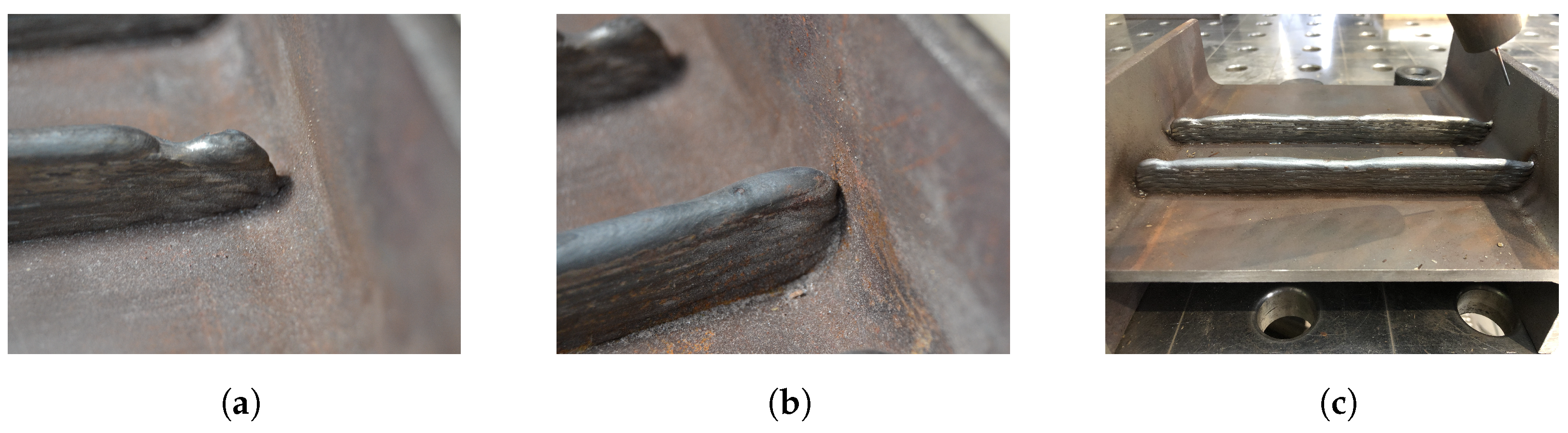
Figure 14a,b show two forms of insufficient connection to the flange wall. The situation shown in
Figure 14a resulted from a too-large rounding radius of the digital profile. This results in a gap between the flange and the WAAM rib after only a few layers. With an adapted smaller fillet, the layers are already brought much closer to the wall of the flange,
Figure 14b. However, the layers are only brought up to the wall without a real bond with the material.
During the first tests it was observed that the connection to the flange is better when it is end of the path. Observed characteristic was same regardless of the printing direction of the layer. One explanation is that all tolerances and deformations during the manufacturing process add up on the opposite side due to the one-sided stop. In
Figure 14c, the side with the stop is on the right. The measured deformations in height were very small but seemed large enough to disturb the sensitive process.
4.3. Alternative Path Strategy
The main strategy for basic path planning was the horizontal slicing of the rib geometry. It was always assumed that the profile was on the side, i.e., on the edges of the flanges.
Figure 15a shows a schematic illustration of horizontal slicing using the example of a full rib.
A great advantage of this approach is that layers can be built horizontally on top of each other. Therefore no dripping due to gravity is anticipated. The problem described in the previous chapters of obtaining a qualitatively sufficient connection to the flanges in this way proved to be over-complicated. Therefore, attempts were made to implement the connection more directly with the help of a different approach to slicing.
The variant in
Figure 15b shows slicing using the example of a rib, in which the paths run along the contours of the substrate profile. The layers are built up from the outside to the inside. Therefore, the advantage of this variant is welding directly onto the flange and avoiding horizontal slicing. Only the end of each layer is guided to the flange. On the other hand, welding vertically creates the additional difficulty of gravity, affecting the stability of the liquid weld metal during the process.
Figure 16 shows a first attempt to test the path strategy.
At layer one, it can be seen that the weld metal drips off at the end of the seam. The reason for this is that the gravity pulls down the liquid weld metal. When moving upwards, however, this guidance is missing so that the still liquid weld metal becomes too heavy and drips off. With the next layer, the error can no longer be compensated for because the irregular surface from the drop formation of the previous layer causes the arc to break off, which does not result in a uniform process. A further test was then started in which the paths were divided in the middle so that welding in the flange area only took place in a downward motion. The adapted path strategy is shown in
Figure 17a. The results of the subsequent test trials are shown in two steps after the first layer in
Figure 17b and the final layer in
Figure 17c.
When comparing the paths from
Figure 17a and the result of the printed tests in the enlarged view of the edge area shown in
Figure 18a, it is noticeable that the layer height in the areas where vertical welding was carried out differs significantly from the horizontally applied sections. Since the weld metal is pulled along during the downward movement, the layers are significantly lower. The missing material solidifies in the areas when the path runs back in the horizontal direction. This leads to an increasing deviation between the digitally planned paths traversed by the robot and the actual structure. In
Figure 18b, the problem is shown schematically. The occurring error accumulates and becomes larger with increasing height.
The connection to the flange is compatible with this path guidance, as welding is done directly onto the flange. Even if the profile geometry deviates, the torch reaches the flange section directly for each layer. A significant disadvantage, however, is that the individual layers vary greatly in height. This circumstance makes it extremely complex to define path guidance in advance with which the desired geometry can be produced true to size. The layer geometry balance could be improved by adjusting the welding parameters. There are already studies where welding parameters have been discussed to build layers vertically [
19]. However, in the context of this work, changing these parameters is not envisaged. Therefore, this path planning strategy is not pursued further here, but material continues to be applied in horizontal layers as far as possible.
Nevertheless, an interesting insight can be gained from the tests just described. Pulling up the weld seam on the flange sides allows the layers to fit much more variably into the profile geometry. It led to optimizing the path guidance explained in the following section.
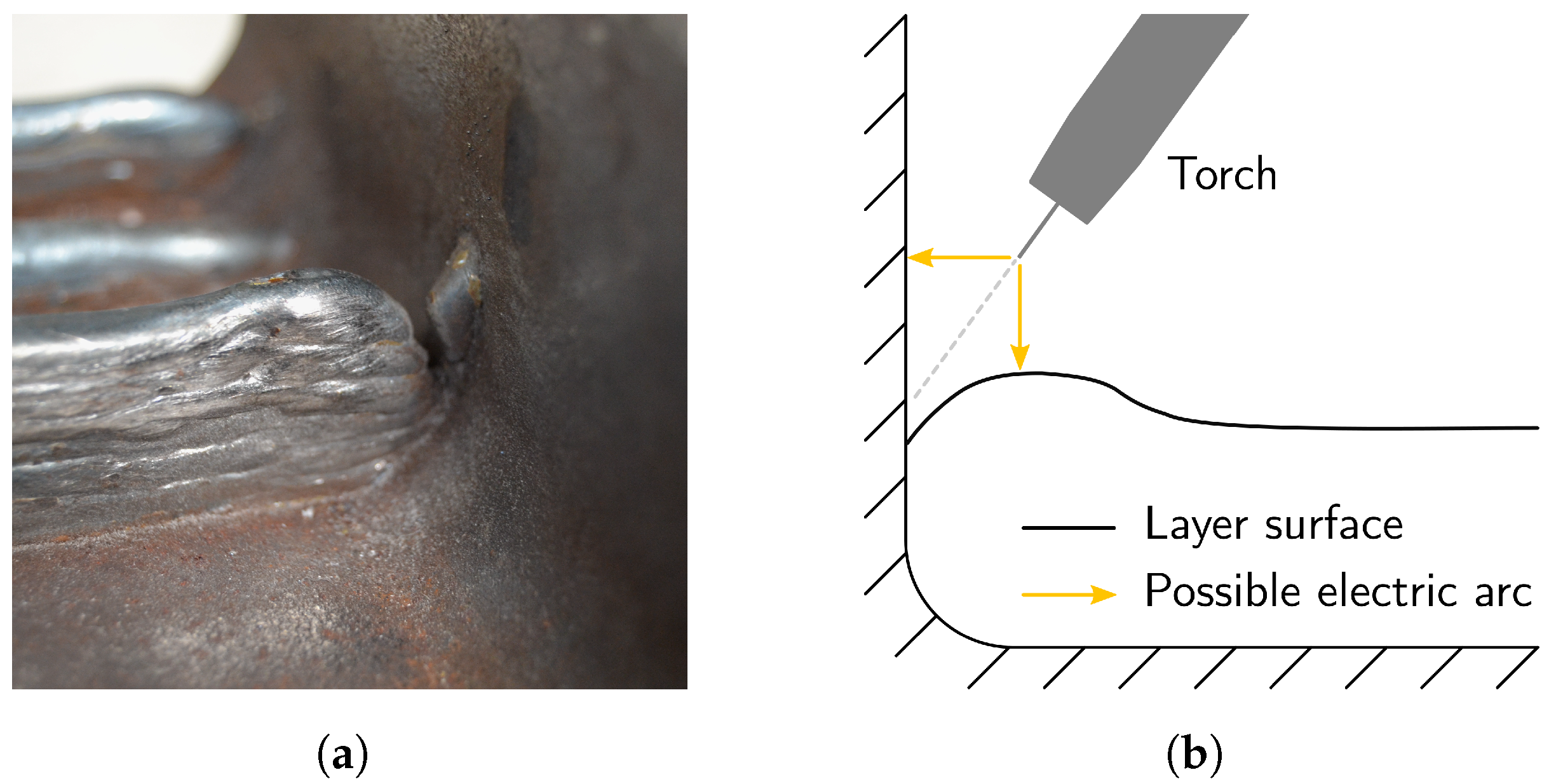
4.4. Path Adaptation for End Returns
With horizontal path guidance, as in
Figure 15a, there are a few points that proved problematic in the first tests, despite careful coordination between actual and digital geometric boundary conditions. Firstly, the point at which the arc ignites is always somewhat critical, as the substrate material still has a significantly lower temperature and must first be melted. Since this is now shortly before the actual layer starts, the process is already completely stable. Another problem is that if a layer has a slight bump at the end or is too short, the arc may ignite in the wrong place, further amplifying the defect. The problem is shown in
Figure 19a. The arc is formed at the shortest distance between the wire tip and the substrate material. Once gaps are created due to defects, several points of attack for the arc can result, as shown in
Figure 19b, depending on the position of the wire tip to the weld start.
By normal path guidance, as shown in
Figure 20a, it is impossible to control the exact ignition point. To further develop the horizontal path guidance, an additional waypoint was added at the ends of the layers to be welded to the flange. This point is a few millimetres above the actual start or end point (see
Figure 20b). The additional point ensures that the arc is already created at the flange, as the starting point is further above the already created layers.
By adjusting the paths, quality of the flange connection could be improved significantly. However, with higher numbers of layers, it was observed that the layers rose more and more obliquely towards the edges. It indicates a higher layer height in these areas, which can be explained by the adjustment of the paths, as the additional spot in each layer causes slightly more weld metal to be deposited at the ends. With the normal path guidance, the layers tended to drop slightly towards the ends due to too little material. Therefore, a good middle ground had to be found to combine the advantageous properties of both strategies.
In
Figure 20c, another modification of the path guidance is shown. The additionally raised waypoint at the ends in the flange area remains. Instead, the corner point (second or penultimate point) is deleted. As a result, the robot no longer moves into the corner at each layer, so slightly less material is separated. The raised start/endpoint still ensures the connection to the wall of the flanges.
5. Final Fabrication of Demonstrators
Final fabrication of the demonstrators was realized using the same setup previously explained in this paper. After calibrating the process parameters and adjusting the path planning method, it was necessary to develop a suitable strategy to make deformations controllable while avoiding permanent deformations.
5.1. Strategies for Reducing Deformations during the Fabrication Process
Due to the high-temperature input from welding, it is to be expected that strong deformations of the substrate would occur during the process. The first tactile tests already indicated this on simple plates.
In steel construction, ribs are usually built symmetrically, i.e., from both sides to the web, to avoid eccentricities. When manufacturing the ribs using WAAM, it also makes sense to apply the material to both sides of the web. It allows the opposing deformations to balance each other out. This procedure is also found in the technical literature [
31,
32].
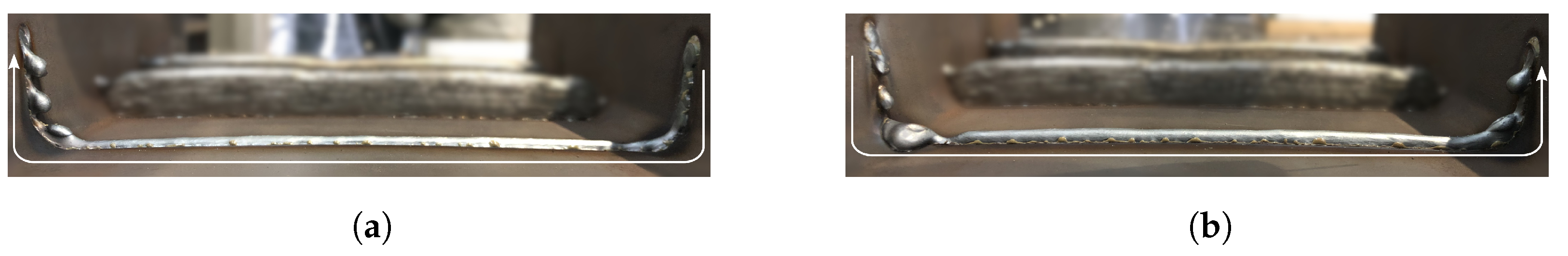
Between
Figure 21a,b, there is a clear bending of the bar on the side of the manufactured rib. The rib applied in a further step on the opposite side causes a deformation in the opposite direction. However, since the existing first rib significantly increases the bar’s stiffness, the reverse deformation is less. It leaves a small but noticeable residual deformation, as shown in
Figure 21c.
In order to prevent this residual deformation, the two sides were manufactured alternately during further tests earlier in the production process. In this way, the deformation caused in the previous section could be directly compensated for in small steps. At the same time, the stiffness gained on both sides of the bar increases with an alternating manufacturing process. In
Figure 22a, the printing intervals are shown by the example of the partial rib design. Concerning this, the course of the measured deformation Δb is displayed in
Figure 22b. Here, it can be seen how the deformations decrease with each added section. Due to this strategy, the maximum deformation amounted to 3 and 4 mm for IIa and IIIa, respectively.
This promising fabrication method focused on deformation countermeasures was used to fabricate the demonstrators. In the further course of the tests, the strategy was always to apply five layers to each side during production before rotating the profile. After 15 layers were printed on both sides, the remaining layers were printed on each side in two final steps. In the case of strong deformations, it occasionally happened that the deformation was not completely compensated for within a change interval. It was possible to react directly to this by starting the next interval on the same side without a change. This case occurred during the manufacturing of demonstrator IIb; the maximum deformation value was 13 mm. This procedure can also save additional valuable time. Only in the last demonstrator object, IIIb, were the described measures insufficient. It was possible to compensate for the deformations by alternate machining at the end. However, the fluctuations in the deformations during the process were more than 15 mm, so big that the dimensional accuracy of the printed WAAM geometry was significantly impaired. In
Figure 23a, it can be seen that the sections on the flanges have significantly different heights. The most likely cause for this is that the flanges tilted outwards due to the severe deformation of the web. Due to this deviation, the digital paths fit less with the actual conditions. However, the geometry is built up incorrectly since the wire is still being pushed forward and material is being applied.
In another test, the manufacturing strategy of alternating printing was further adapted. The layers were again divided into three sections. By alternating the sides earlier, it can react more directly to the deformations.
Figure 23b illustrates the additional division of the printing sections. Here, the ribs were divided into three sections from the inside to the outside.
The lower layers were built following the sequence 1.1-1.2-2.1-2.2. This way, high stability against excessive deformation could be achieved directly with the first layers over the inner ribs. The maximum deformation value using this strategy was only about 3 mm.
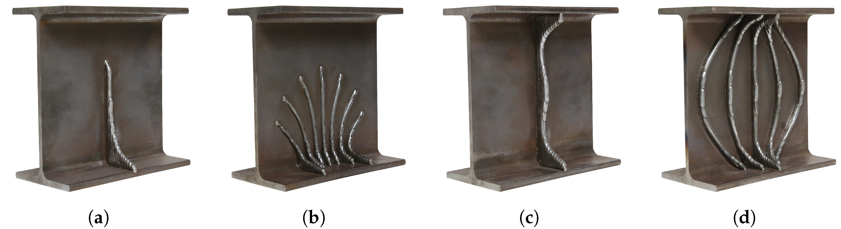
5.2. Outcomes of the Fabrication Process
The manufactured demonstrators for stiffeners of standard steel profiles built in the scope of this research are presented in the
Figure 24. The high heat input during welding sometimes leads to severe web deformation. The strategy described above of alternately applying the material on each side enabled the distortion to be well controlled. In the end, the deformations of the web could even be compensated to such an extent that no manually measurable deviations were detectable after production.
Figure 25 presents some detailed photos of each demonstrator. Due to the adjustments of the path planning process described in the previous section, a reliable and uniform connection of the stiffeners to the flange was produced successfully. The WAAM geometries were also successfully assembled out of flat and uniform layers.
No measurable deformations could occur during the production of the reinforcements of the flanges of a steel profile. Due to the double-T geometry, the flanges are held in their plane by the adjoining web, significantly increasing the stiffness. By organizing the layers for the simultaneous construction of the substructures, waiting times for the cooling of individual areas could be avoided. The final result of the strengthened steel profile with WAAM geometries on the upper and lower flange is shown in
Figure 26a. A detailed view of the two geometry versions is provided in
Figure 26b,c.
5.3. Production Times
The duration of the production is a decisive factor in the question of whether the process is used. The build-up rates were calculated by multiplying the wire feed rate by the wire diameter. The index “welding” refers only to periods in which welding takes place; “total” includes all work steps. The turning process, in particular, considerably increases the manufacturing time. The times calculated here included a flat rate of 30 s per turning process. In any case, this step would have to be automated in a future application to save time. The production times and calculated build-up rates are presented in
Table 3.
The shortest production time was needed for partial rib IIa. It is because the amount of material applied is the least of all the rib designs. Since the ribs, according to approach B, have significantly higher material volumes, a comparison over time is of limited significance. It is more interesting to look at the build-up rates. Here, the B ribs perform better.
Where applicable, different travel speed of the transfer movement between the endpoint of the already travelled path and the starting point of the following path should be used. Here, a considerable amount of time can be saved because the travel speed during the process is very low compared to the possible travel speed of the robot. Particularly in the case of structures that are becoming more complex, where several parts are being built up at the same time, the torch is moved down several times and then started up again at a different point. In the context of this work, this practice was beneficial for producing objects IIb and IIIb. Here, no significant waiting times were necessary, as the geometries consist of several sections. This way, the layers can always be applied alternately. In order not to lose too much time with the many repositioning movements, the speed was increased considerably. While the travel speed remained at 800 mm/min during welding, it was increased to 2000 mm/min during the repositioning phases. As a result, the time required could be reduced by up to 45% using IIIb as an example.
6. Discussion
At the beginning of the theoretical part of the work, some boundary conditions were discussed to develop suitable designs for WAAM-manufactured ribs based on these. Special attention was paid to the material steel and its development, as well as the different manufacturing processes of rolled sections compared to additively manufactured WAAM geometries. Likewise, the structural function of ribs was analyzed based on the normative calculation specifications. As a result, two different design approaches could be worked out, which were subsequently produced with the setup. In addition, approaches for possible reinforcements of the flanges for areas with increased bending stress were proposed.
During the tests, several factors turned out to have a decisive influence on the quality of the results. The most important point was to adjust the path planning in such a way that the connection of the welding layers to the flange could be made with a sufficient bond. To this end, several attempts were made to adjust the available parameters of the robot programming step by step so that the torch could reliably reach the decisive points to bring the layers evenly close to the flange. The manufacturing tolerances of rolled sections also played a role in this process in advance. Each profile had to be precisely measured and adjusted in the digital model to plan the paths. Further development of an industrially applicable setup would be the possibility of recording the geometric boundary conditions through a scanner. Thus, the path planning could be adjusted automatically based on the scanned geometry. It would also be possible to compensate for defects during the process. However, the demonstrators presented here are design proposals for now. Additional FEM analyses and destruction tests must be undertaken to evaluate the actual load-bearing capacity.
The second important point concerns that the manufacturing process introduces a lot of energy in the form of heat into the printed semi-finished product, resulting in significant deformations. The geometries were applied in parallel on both sides to compensate for these. In this way, the deformations of individual work steps could be compensated for in the subsequent section. With the aid of this strategy, it was possible to produce all the test objects without significant distortion. However, it should be kept in mind that the process generates residual stresses. Likewise, the process of constant turning turned out to be time-consuming. Further automation in the form of a controlled turning device would be ideal. It could also reduce the influence of gravity, which in turn would open up new possibilities for path strategies. Further investigations regarding the reduction of process-related heat input could also be useful. Faster travel speeds and even narrower layers would probably further reduce heat input. Due to the geometry’s flexibility, the objects’ stability can be generated more from the shape and less from the material thickness of the walls. Attempts to apply reinforcements directly to the flange proved unproblematic in terms of deformation.
7. Conclusions
The present work proposes an experimental and conceptual study on how to strengthen steel I-beam profiles utilizing the WAAM process. The study was carried out first from a theoretical point of view, understanding possible strengthening solutions and fabrication limitations based on the specific setup. Then, different design considerations were drawn out, and various approaches to reinforce I-beam profiles were first studied and then validated through the fabrication of demonstrators. The results also provide useful insights into the influence of WAAM parts printed on conventionally rolled steel members. The tests proved that the relative deformation of the WAAM part on the rolled products could be well controlled by fine-tuning the printing process and printing strategy. It was also shown that in order to reach a higher precision and the overall higher quality, additional step between the design and the fabrication has to be conducted.
Nonetheless, the extent to which the residual stresses affect the load-bearing capacity remains unexplored. The effects of heat input due to the manufacturing process should not be neglected and should be anticipated in further research. Path planning is a very dynamic and complex process in WAAM production, which could be significantly improved by adding scanning technology. WAAM manufacturing of reinforcements would significantly increase its potential in a completely automatized process, specifically applied to highly complex geometries.


 ,
, 


