


The Effect of Magnetized Water on the Fresh and Hardened Properties of Slag/Fly Ash-Based Cementitious Composites

 , , ,
, , ,
Abstract
1. Introduction
2. Experimental Program
2.1. Materials
2.2. Mixture Proportions
2.3. Test Methods
2.3.1. Fresh Properties
2.3.2. Compressive Strength
2.3.3. Water Absorption
2.3.4. Rapid Chloride Ion Permeability
2.3.5. Mercury Intrusion Porosimetry (MIP)
2.3.6. Microstructure Analysis
3. Results and Discussion
3.1. Fresh Properties
3.1.1. Setting Characteristics
3.1.2. Consistency
3.2. Compressive Strength
3.3. Water Absorption
3.4. Rapid Chloride Ion Permeability
3.5. Mercury Intrusion Porosimetry
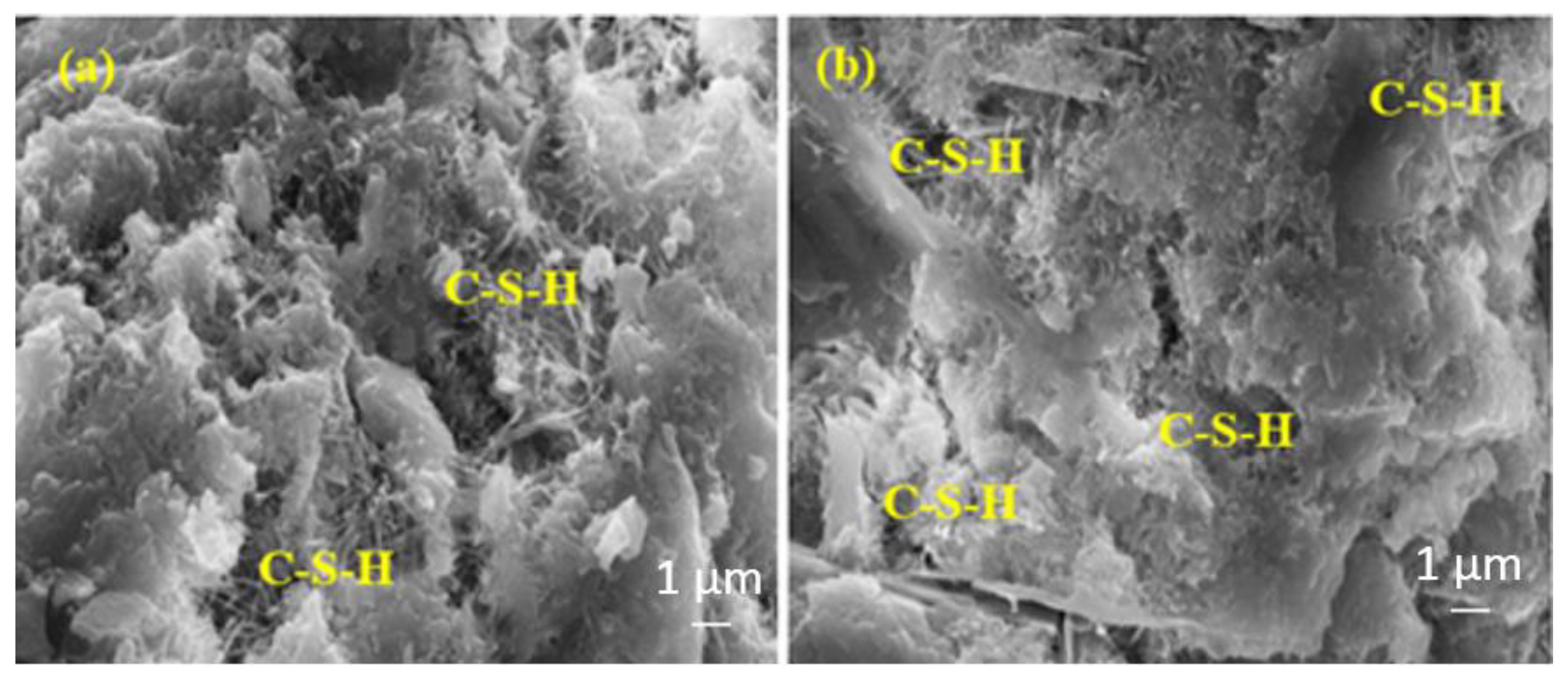
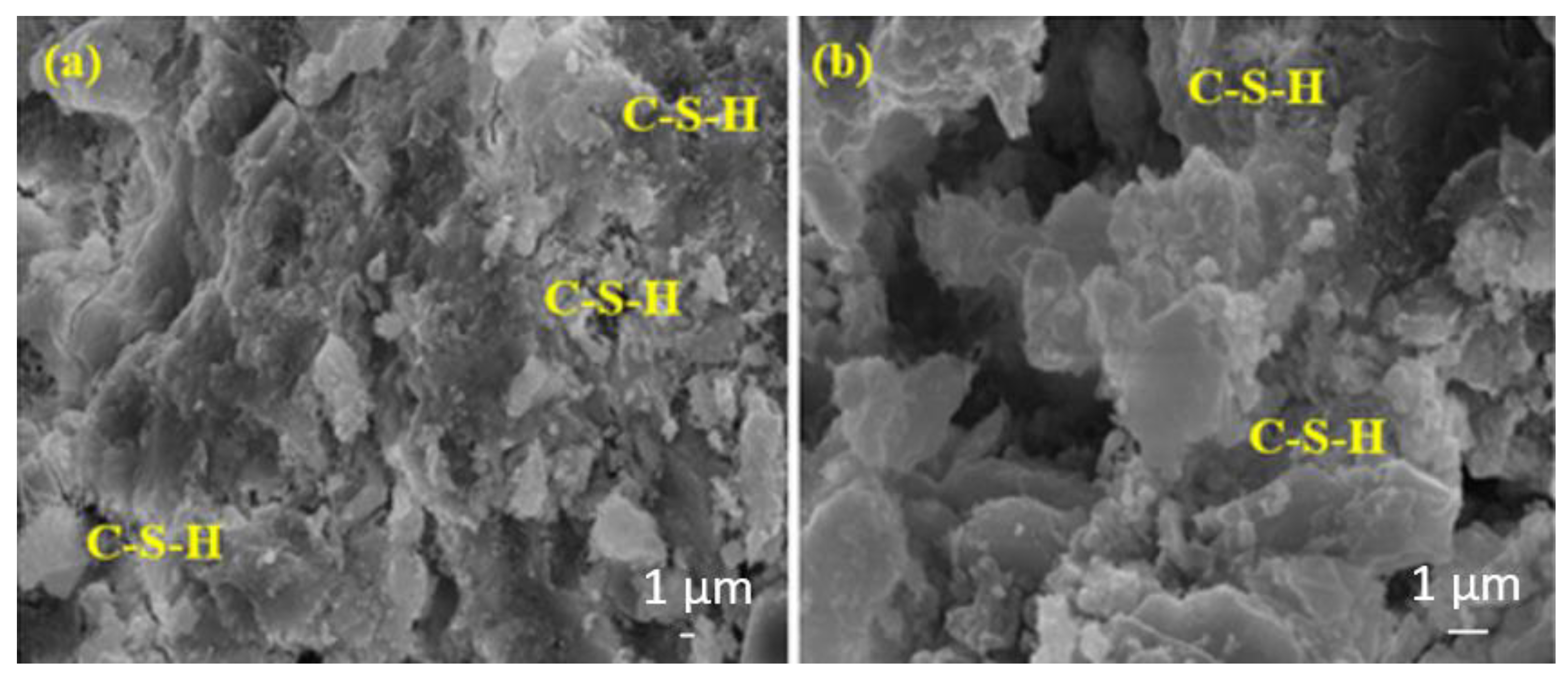
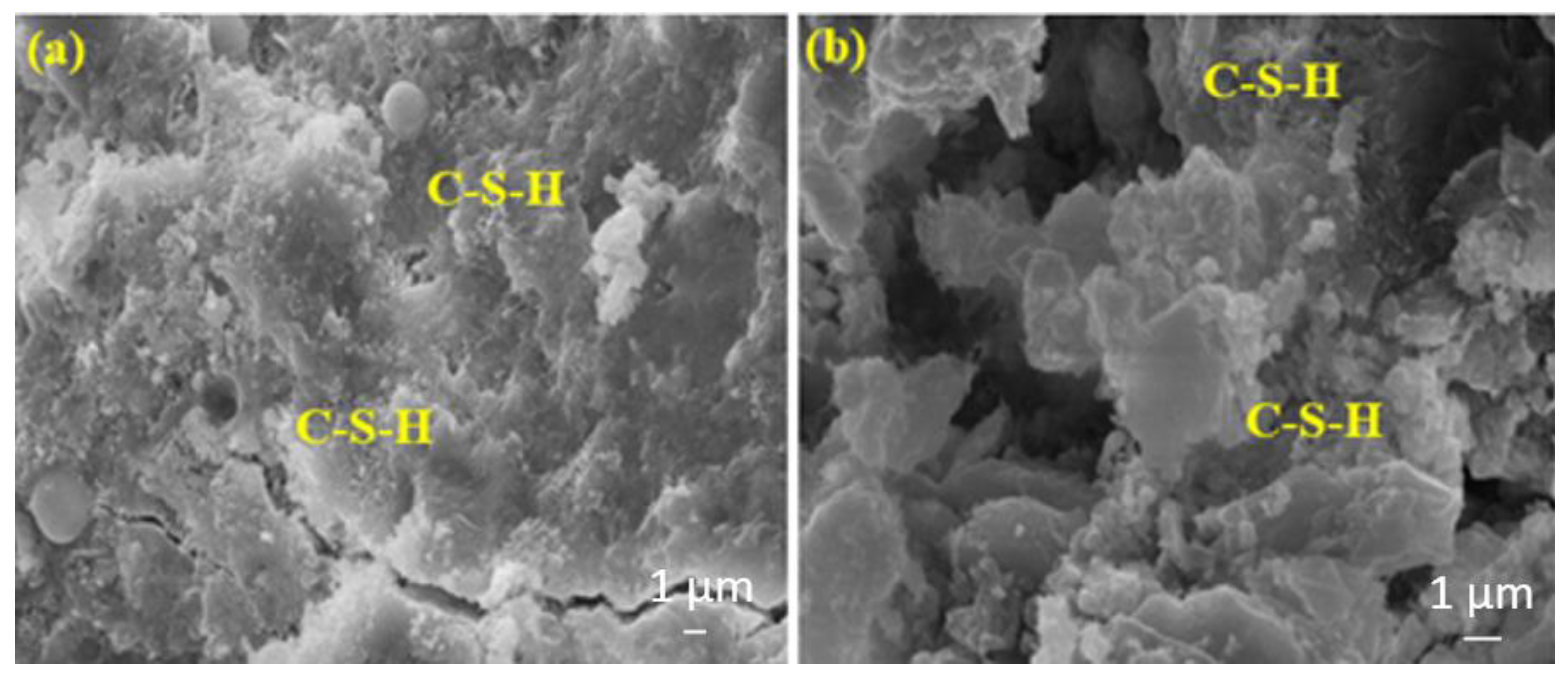
3.6. Microstructure Analysis
4. Conclusions
- (1)
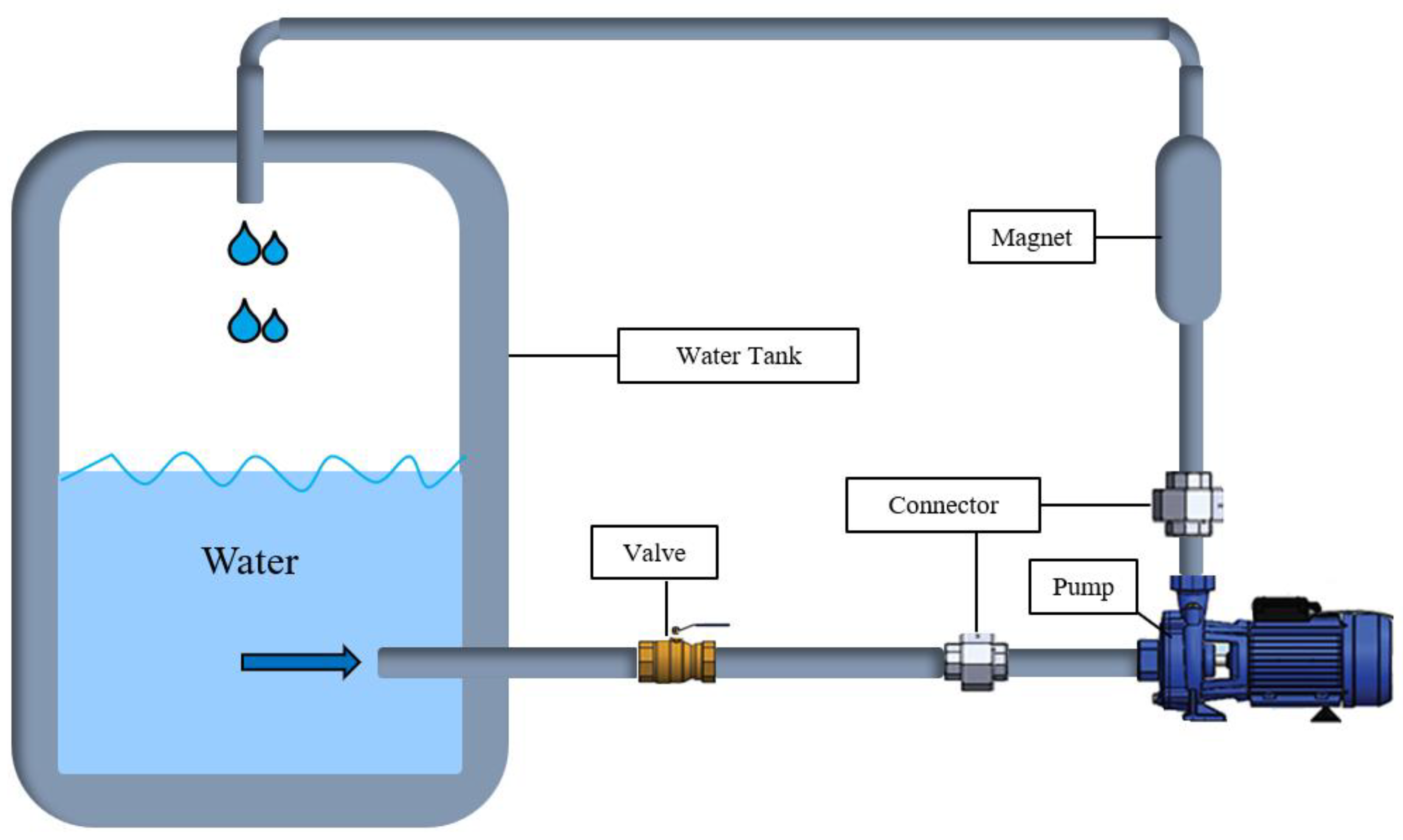
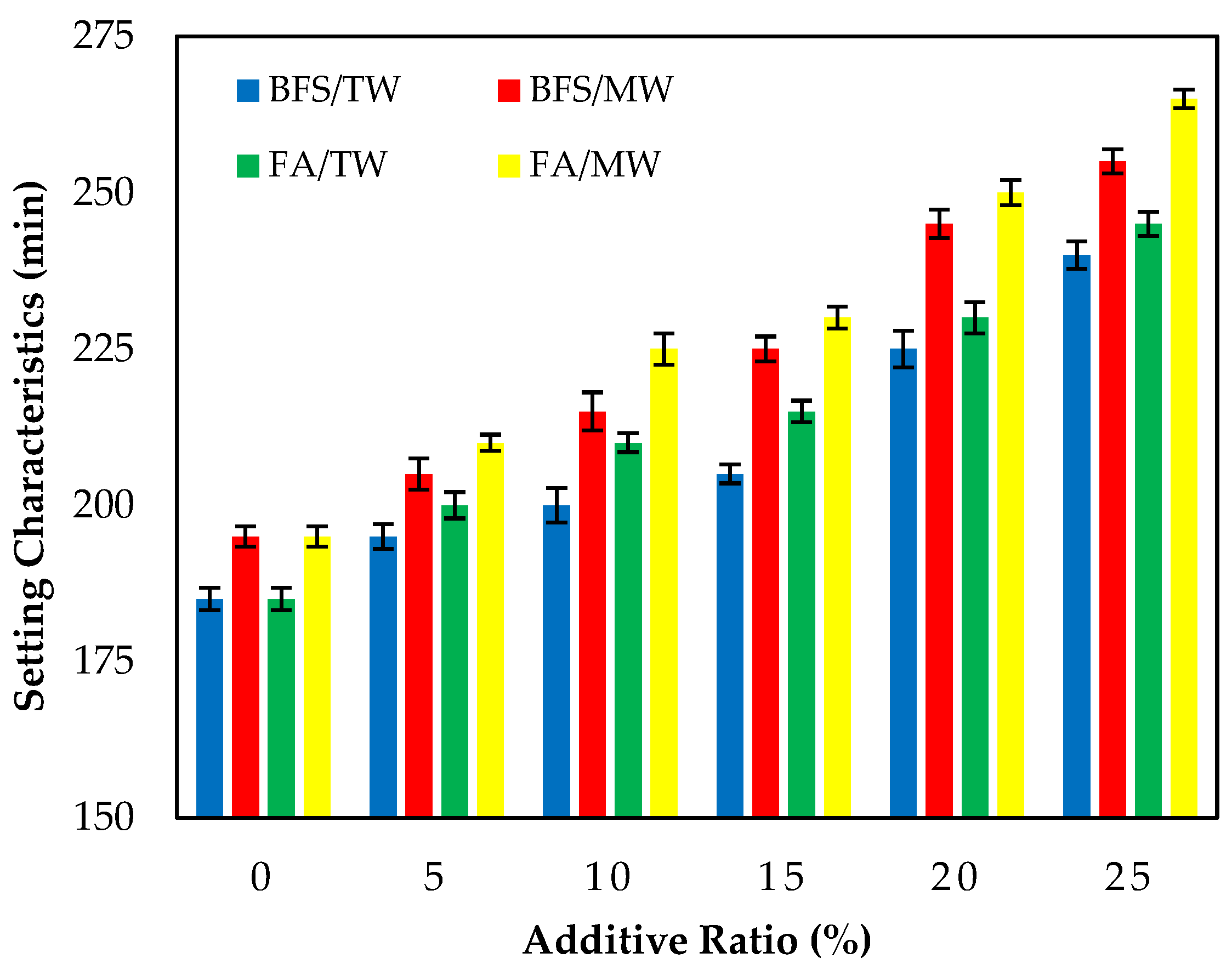
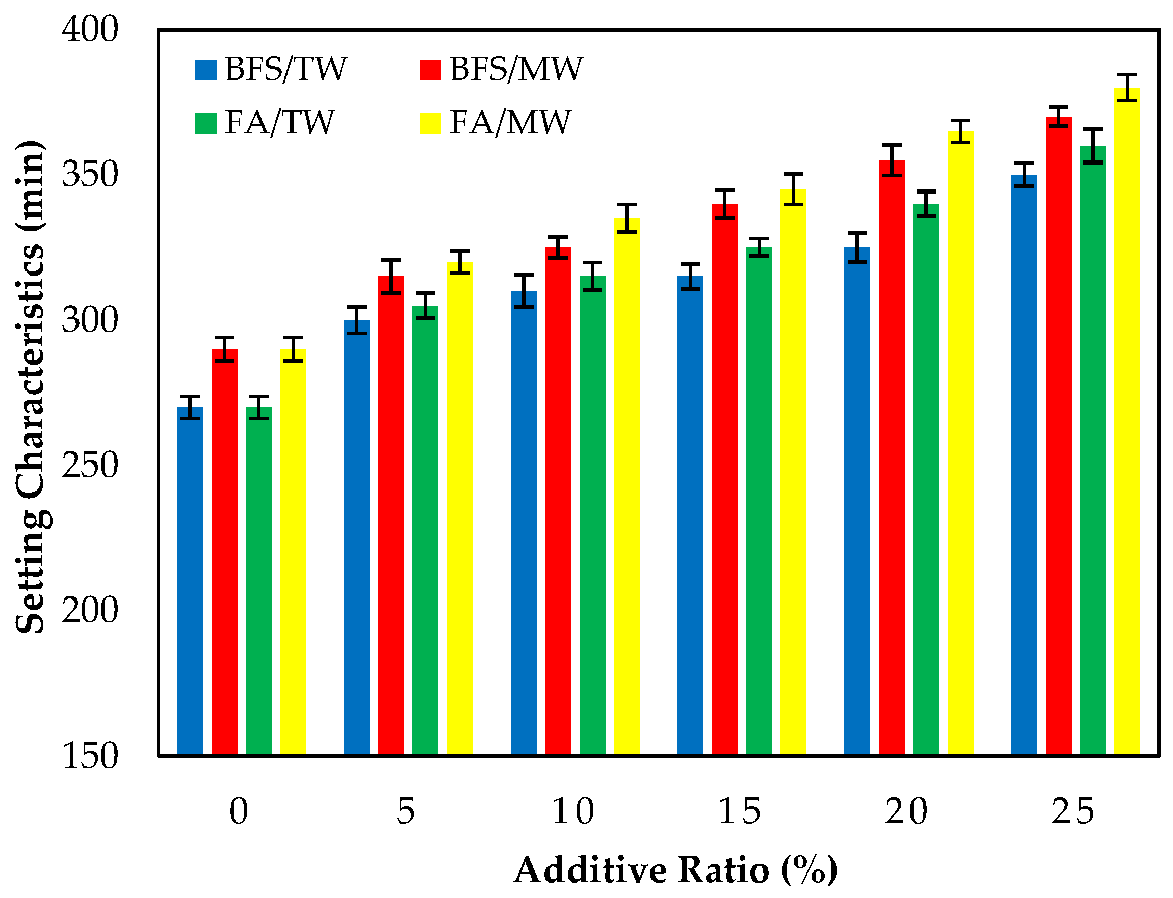
- The initial and final setting times of cement pastes produced with MW were longer than those produced with TW. The consistency of fresh cement mortars prepared with MW increased compared to those prepared with TW for both the FA and BFS additives. This can be attributed to the fact that when the water is passed through the magnetic field, the water clusters are broken up and separated into smaller water molecules, resulting in the mortars being more fluid. The flow diameters increased as the FA replacement ratio increased, regardless of the water type;
- (2)
- The compressive strengths for both the FA and BFS-based samples increased with the use of MW. This might be attributed to the binder material hydrating more with the MW;
- (3)
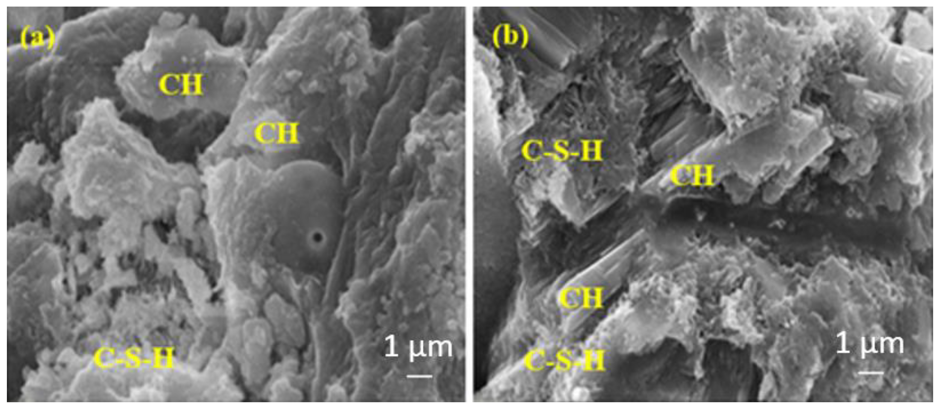
- The mortar mixes produced with MW have a lower water absorption than those produced with TW. The samples produced with MW have lower RCPT results than those produced with TW at all ages. The chloride ion permeability increased as both the FA and BFS replacement ratios increased, regardless of the water type. This might be attributed to the increase in the activity of MW, improving the hydration of the binder and providing a less porous structure of the cement matrix;
- (4)
- Using up to 25% FA/BFS in cementitious composites prepared with MW is recommended. Thus, the use of cement will be saved, the amount of CO2 released to nature will be reduced, and significant contributions will be made in terms of sustainability;
- (5)
- With the use of MW, the workability of cementitious composites will increase, and it will reduce the use of plasticizer chemicals in cementitious composites; therefore, the cost will decrease;
- (6)
- It is thought that using MW will provide significant advantages for the sector representatives. Although the initial installation cost of the MW system is seen as high, the installation cost will be met by the future cost savings;
- (7)
- In further studies, the use of MW on the properties of geopolymers/alkali-activated materials could be investigated. In addition, the effects of MW on shrinkage cracks and the hydration heat of cementitious composites could be examined.
Author Contributions
Funding
Institutional Review Board Statement
Informed Consent Statement
Data Availability Statement
Conflicts of Interest
References
- Sevim, Ö.; Demir, İ. Optimization of fly ash particle size distribution for cementitious systems with high compactness. Constr. Build. Mater. 2019, 195, 104–114. [Google Scholar] [CrossRef]
- Kim, T.; Davis, J.M.; Ley, M.T.; Kang, S.; Amrollahi, P. Fly ash particle characterization for predicting concrete compressive strength. Constr. Build. Mater. 2018, 165, 560–571. [Google Scholar] [CrossRef]
- Ahmaruzzaman, M. A review on the utilization of fly ash. Prog. Energy Combust. Sci. 2010, 36, 327–363. [Google Scholar] [CrossRef]
- Hemalatha, T.; Ramaswamy, A. A review on fly ash characteristics-Towards promoting high volume utilization in developing sustainable concrete. J. Clean. Prod. 2017, 147, 546–559. [Google Scholar] [CrossRef]
- Blissett, R.S.; Rowson, N.A. A review of the multi-component utilization of coal fly ash. Fuel 2012, 97, 1–23. [Google Scholar] [CrossRef]
- Sevim, Ö.; Demir, İ. Physical and permeability properties of cementitious mortars having fly ash with optimized particle size distribution. Cem. Concr. Compos. 2019, 96, 266–273. [Google Scholar] [CrossRef]
- Tastan, E.O.; Edil, T.B.; Benson, C.H.; Aydilek, A.H. Stabilization of organic soils with fly ash. J. Geotech. Geoenviron. Eng. 2011, 137, 819–833. [Google Scholar] [CrossRef]
- Basu, M.; Pande, M.; Bhadoria, P.B.S.; Mahapatra, S.C. Potential fly-ash utilization in agriculture: A global review. Prog. Nat. Sci. 2009, 19, 1173–1186. [Google Scholar] [CrossRef]
- Movilla-Quesada, D.; Muñoz, O.; Raposeiras, A.C.; Castro-Fresno, D. Thermal suspectability analysis of the reuse of fly ash from cellulose industry as contribution filler in bituminous mixtures. Constr. Build. Mater. 2018, 160, 268–277. [Google Scholar] [CrossRef]
- Rameshwaran, P.M.; Madhavi, T.C. Flexural behaviour of fly ash based geopolymer concrete. Mater. Today Proc. 2021, 46, 3423–3425. [Google Scholar] [CrossRef]
- Leng, F.; Feng, N.; Lu, X. An experimental study on the properties of resistance to diffusion of chloride ions of fly ash and blast furnace slag concrete. Cem. Concr. Res. 2000, 30, 989–992. [Google Scholar] [CrossRef]
- Demir, İ.; Güzelkücük, S.; Sevim, Ö. Effects of sulfate on cement mortar with hybrid pozzolan substitution. Eng. Sci. Technol. Int. J. 2018, 21, 275–283. [Google Scholar] [CrossRef]
- Erdoğdu, K.; Türker, P. Effects of fly ash particle size on strength of Portland cement fly ash mortars. Cem. Concr. Res. 1998, 28, 1217–1222. [Google Scholar] [CrossRef]
- Pandian, N.S. Fly ash characterization with reference to geotechnical applications. J. Indian Inst. Sci. 2004, 84, 189–216. [Google Scholar]
- Shaikh, F.U.; Supit, S.W. Compressive strength and durability properties of high volume fly ash (HVFA) concretes containing ultrafine fly ash (UFFA). Constr. Build. Mater. 2015, 82, 192–205. [Google Scholar] [CrossRef]
- Das, B.; Prakash, S.; Reddy, P.S.R.; Misra, V.N. An overview of utilization of slag and sludge from steel industries. Resour. Conserv. Recycl. 2007, 50, 40–57. [Google Scholar] [CrossRef]
- Özbay, E.; Erdemir, M.; Durmuş, H.İ. Utilization and efficiency of ground granulated blast furnace slag on concrete properties—A review. Constr. Build. Mater. 2016, 105, 423–434. [Google Scholar] [CrossRef]
- Shi, C.; Qian, J. High performance cementing materials from industrial slags—A review. Resour. Conserv. Recycl. 2000, 29, 195–207. [Google Scholar] [CrossRef]
- ACI 233R-03; Slag Cement in Concrete and Mortar. ACI Committee: Detroit, MI, USA, 2003.
- Ballim, Y.; Graham, P.C. The effects of supplementary cementing materials in modifying the heat of hydration of concrete. Mater. Struct. 2009, 42, 803–811. [Google Scholar] [CrossRef]
- Gesoğlu, M.; Güneyisi, E.; Özbay, E. Properties of self-compacting concretes made with binary, ternary, and quaternary cementitious blends of fly ash, blast furnace slag and silica fume. Constr. Build. Mater. 2009, 23, 1847–1854. [Google Scholar] [CrossRef]
- Xie, J.F.; Huang, Y.X.; Li, W.W.; Song, X.N.; Xiong, L.; Yu, H.Q. Efficient electrochemical CO2 reduction on a unique chrysanthemum-like Cu nanoflower electrode and direct observation of carbon deposite. Electrochim. Acta 2014, 139, 137–144. [Google Scholar] [CrossRef]
- Madlool, N.A.; Saidur, R.; Hossain, M.S.; Rahim, N.A. A critical review on energy use and savings in the cement industries. Renew. Sustain. Energy Rev. 2011, 15, 2042–2060. [Google Scholar] [CrossRef]
- Meyer, C. The greening of the concrete industry. Cem. Concr. Compos. 2009, 31, 601–605. [Google Scholar] [CrossRef]
- Sun, Y.; Wang, K.Q.; Lee, H.S. Prediction of compressive strength development for blended cement mortar considering fly ash fineness and replacement ratio. Constr. Build. Mater. 2021, 271, 121532. [Google Scholar] [CrossRef]
- Jouzdani, B.E.; Reisi, M. Effect of magnetized water characteristics on fresh and hardened properties of self-compacting concrete. Constr. Build. Mater. 2020, 242, 118196. [Google Scholar] [CrossRef]
- Felekoğlu, B.; Türkel, S.; Baradan, B. Effect of water/cement ratio on the fresh and hardened properties of self-compacting concrete. Build. Environ. 2007, 42, 1795–1802. [Google Scholar] [CrossRef]
- Hover, K.C. The influence of water on the performance of concrete. Constr. Build. Mater. 2011, 25, 3003–3013. [Google Scholar] [CrossRef]
- Karimipour, A.; Edalati, M.; Brito, J. Influence of magnetized water and water/cement ratio on the properties of untreated coal fine aggregates concrete. Cem. Concr. Compos. 2021, 122, 104121. [Google Scholar] [CrossRef]
- Su, N.; Wu, Y.H. Effect of magnetic field treated water on mortar and concrete containing fly ash. Cem. Concr. Compos. 2003, 25, 681–688. [Google Scholar] [CrossRef]
- Su, N.; Wu, Y.H.; Mar, C.Y. Effect of magnetic water on the engineering properties of concrete containing granulated blast-furnace slag. Cem. Concr. Res. 2000, 30, 599–605. [Google Scholar] [CrossRef]
- Ghorbani, S.; Gholizadeh, M.; Brito, J. Effect of magnetized water on the mechanical and durability properties of concrete block pavers. Materials 2018, 11, 1647. [Google Scholar] [CrossRef]
- Toledo, E.J.L.; Ramalho, T.C.; Magriotis, Z.M. Influence of magnetic field on physical–chemical properties of the liquid water: Insights from experimental and theoretical models. J. Mol. Struct. 2008, 888, 409–415. [Google Scholar] [CrossRef]
- Oleinikova, A.; Smolin, N.; Brovchenko, I. Influence of water clustering on the dynamics of hydration water at the surface of a lysozyme. Biophys. J. 2007, 93, 2986–3000. [Google Scholar] [CrossRef] [PubMed]
- Wei, H.; Wang, Y.; Luo, J. Influence of magnetic water on early-age shrinkage cracking of concrete. Constr. Build. Mater. 2017, 147, 91–100. [Google Scholar] [CrossRef]
- Xiao-Feng, P.; Bo, D. The changes of macroscopic features and microscopic structures of water under influence of magnetic field. Phys. B Condens. Matter 2008, 403, 3571–3577. [Google Scholar]
- Ahmed, H.I. Behavior of magnetic concrete incorporated with Egyptian nano alumina. Constr. Build. Mater. 2017, 150, 404–408. [Google Scholar] [CrossRef]
- Esfahani, A.R.; Reisi, M.; Mohr, B. Magnetized water effect on compressive strength and dosage of superplasticizers and water in self-compacting concrete. J. Mater. Civ. Eng. 2018, 30, 04018008. [Google Scholar] [CrossRef]
- Ghorbani, S.; Tao, Z.; Brito, J.; Tavakkolizadeh, M. Effect of magnetized water on foam stability and compressive strength of foam concrete. Constr. Build. Mater. 2019, 197, 280–290. [Google Scholar] [CrossRef]
- Venkatesh, S.; Jagannathan, P. An experimental study on the effect of magnetized water on mechanical properties of concrete. IOP Conf. Ser. Mater. Sci. Eng. 2020, 912, 032081. [Google Scholar] [CrossRef]
- Abdel-Magid, T.I.M.; Hamdan, R.M.; Abdelgader, A.A.B.; Omer, M.E.A.; Ahmed, N.M.R.A. Effect of magnetized water on workability and compressive strength of concrete. Procedia Eng. 2017, 193, 494–500. [Google Scholar] [CrossRef]
- Ghorbani, S.; Mohammadi-Khatami, M.; Ghorbani, S.; Elmi, A.; Farzan, M.; Soleimani, V.; Negahban, M.; Tam, V.W.Y.; Tavakkolizadeh, M. Effect of magnetized water on the fresh, hardened and durability properties of mortar mixes with marble waste dust as partial replacement of cement. Constr. Build. Mater. 2021, 267, 121049. [Google Scholar] [CrossRef]
- Choi, M.S.; Kim, Y.S.; Kim, J.H.; Kim, J.S.; Kwon, S.H. Effects of an externally imposed electromagnetic field on the formation of a lubrication layer in concrete pumping. Constr. Build. Mater. 2014, 61, 18–23. [Google Scholar] [CrossRef]
- Barham, W.S.; Albiss, B.; Latayfeh, O. Influence of magnetic field treated water on the compressive strength and bond strength of concrete containing silica fume. J. Build. Eng. 2021, 33, 101544. [Google Scholar] [CrossRef]
- Afshin, H.; Gholizadeh, M.; Khorshidi, N. Improving mechanical properties of high strength concrete by magnetic water technology. Sci. Iran. 2010, 17, 74–79. [Google Scholar]
- Prabakaran, E.; Vijayakumar, A.; Rooby, J.; Nithya, M.A. A comparative study of polypropylene fiber reinforced concrete for various mix grades with magnetized water. Mater. Today Proc. 2021, 45, 123–127. [Google Scholar] [CrossRef]
- Gholhaki, M.; Kheyroddin, A.; Hajforoush, M.; Kazemi, M. An investigation on the fresh and hardened properties of self-compacting concrete incorporating magnetic water with various pozzolanic materials. Constr. Build. Mater. 2018, 158, 173–180. [Google Scholar] [CrossRef]
- TS EN 197-1; Cement—Part 1: Composition, Specifications and Conformity Criteria for Common Cements. Turkish Standard Institution: Ankara, Turkey, 2012.
- TS EN 196-1; Methods of Testing Cement—Part 1: Determination of Strength. Turkish Standard Institution: Ankara, Turkey, 2016.
- TS EN 196-3; Methods of Testing Cement—Part 3: Determination of Setting Time and Soundness. Turkish Standards Institution: Ankara, Turkey, 2017.
- TS EN 12350-5; Testing Fresh Concrete—Part 5: Flow Table Test. Turkish Standard Institution: Ankara, Turkey, 2019.
- ASTM C642-21; Standard Test Method for Density, Absorption, and Voids in Hardened Concrete. ASTM International: West Conshohocken, PA, USA, 2021.
- ASTM C1202-19; Standard Test Method for Electrical Indication of Concrete’s Ability to Resist Chloride Ion Penetration. ASTM International: West Conshohocken, PA, USA, 2019.
- Diamond, S. Mercury porosimetry: An inappropriate method for the measurement of pore size distributions in cement-based materials. Cem. Concr. Res. 2000, 30, 1517–1525. [Google Scholar] [CrossRef]
- Yu, Z.; Ye, G. The pore structure of cement paste blended with fly ash. Constr. Build. Mater. 2013, 45, 30–35. [Google Scholar] [CrossRef]
- Zhao, H.; Sun, W.; Wu, X.; Gao, B. The properties of the self-compacting concrete with fly ash and ground granulated blast furnace slag mineral admixtures. J. Clean. Prod. 2015, 95, 66–74. [Google Scholar] [CrossRef]
- Brooks, J.J.; Johari, M.A.M.; Mazloom, M. Effect of admixtures on the setting times of high-strength concrete. Cem. Concr. Compos. 2000, 22, 293–301. [Google Scholar] [CrossRef]
- Gesoglu, M.; Ozbay, E. Effects of mineral admixtures on fresh and hardened properties of self-compacting concretes: Binary, ternary and quaternary systems. Mater. Struct. 2007, 40, 923–937. [Google Scholar] [CrossRef]
- Sevim, O.; Baran, M.; Demir, S. Mechanical and physical properties of cementitious composites containing fly ash or slag classified with help of particle size distribution. Rom. J. Mater. 2021, 51, 67–77. [Google Scholar]
- Lee, S.H.; Kim, H.J.; Sakai, E.; Daimon, M. Effect of particle size distribution of fly ash–cement system on the fluidity of cement pastes. Cem. Concr. Res. 2003, 33, 763–768. [Google Scholar] [CrossRef]
- Sevim, O.; Sengul, C.G. Comparison of the influence of silica-rich supplementary cementitious materials on cement mortar composites: Mechanical and microstructural assessment. Silicon 2021, 13, 1675–1690. [Google Scholar] [CrossRef]
- Sevim, O.; Alakara, E.H.; Guzelkucuk, S. Fresh and hardened properties of cementitious composites incorporating firebrick powder from construction and demolition waste. Buildings 2023, 13, 45. [Google Scholar] [CrossRef]
- Wei, J.; Cen, K. Empirical assessing cement CO2 emissions based on China’s economic and social development during 2001–2030. Sci. Total Environ. 2019, 653, 200–211. [Google Scholar] [CrossRef]
- Alhawat, M.; Ashour, A.; Yildirim, G.; Aldemir, A.; Sahmaran, M. Properties of geopolymers sourced from construction and demolition waste: A review. J. Build. Eng. 2022, 50, 104104. [Google Scholar] [CrossRef]
- Giergiczny, Z. Fly ash and slag. Cem. Concr. Res. 2019, 124, 105826. [Google Scholar] [CrossRef]
- Chindaprasirt, P.; Jaturapitakkul, C.; Sinsiri, T. Effect of fly ash fineness on microstructure of blended cement paste. Constr. Build. Mater. 2007, 21, 1534–1541. [Google Scholar] [CrossRef]
- Kim, S.J.; Yang, K.H.; Moon, G.D. Hydration characteristics of low-heat cement substituted by fly ash and limestone powder. Materials 2015, 8, 5847–5861. [Google Scholar] [CrossRef]


| Chemical Composition (%) | OPC | FA | BFS |
|---|---|---|---|
| SiO2 | 21.02 | 57.80 | 34.82 |
| Al2O3 | 5.38 | 20.90 | 17.73 |
| Fe2O3 | 3.22 | 5.25 | 0.65 |
| CaO | 62.59 | 7.84 | 38.22 |
| MgO | 1.98 | 1.78 | 5.48 |
| Na2O | 0.22 | 2.19 | 0.46 |
| K2O | 0.51 | 1.61 | 1.51 |
| SO3 | 3.11 | 0.37 | 0.55 |
| Other elements | 1.97 | 2.26 | 0.58 |
| Physical properties | |||
| Specific gravity (unitless) | 3.18 | 2.04 | 2.87 |
| Blaine fineness (cm2/g) | 3356 | 2945 | 3925 |
| Loss on ignition | 1.58 | 1.32 | 1.43 |
| Mixture ID. | Water Type | Water (g) | FA (%) | BFS (%) | FA (g) | BFS (g) | Cement (g) | Sand (g) |
|---|---|---|---|---|---|---|---|---|
| RefTW | Tap Water | 225 | 0 | - | 0.0 | - | 450.0 | 1350 |
| FA5TW | 225 | 5 | - | 22.5 | - | 427.5 | 1350 | |
| FA10TW | 225 | 10 | - | 45.0 | - | 405.0 | 1350 | |
| FA15TW | 225 | 15 | - | 67.5 | - | 382.5 | 1350 | |
| FA20TW | 225 | 20 | - | 90.0 | - | 360.0 | 1350 | |
| FA25TW | 225 | 25 | - | 112.5 | - | 337.5 | 1350 | |
| BFS5TW | 225 | - | 5 | - | 22.5 | 427.5 | 1350 | |
| BFS10TW | 225 | - | 10 | - | 45.0 | 405.0 | 1350 | |
| BFS15TW | 225 | - | 15 | - | 67.5 | 382.5 | 1350 | |
| BFS20TW | 225 | - | 20 | - | 90.0 | 360.0 | 1350 | |
| BFS25TW | 225 | - | 25 | - | 112.5 | 337.5 | 1350 | |
| RefMW | Magnetized Water | 225 | 0 | - | 0.0 | - | 450.0 | 1350 |
| FA5MW | 225 | 5 | - | 22.5 | - | 427.5 | 1350 | |
| FA10MW | 225 | 10 | - | 45.0 | - | 405.0 | 1350 | |
| FA15MW | 225 | 15 | - | 67.5 | - | 382.5 | 1350 | |
| FA20MW | 225 | 20 | - | 90.0 | - | 360.0 | 1350 | |
| FA25MW | 225 | 25 | - | 112.5 | - | 337.5 | 1350 | |
| BFS5MW | 225 | - | 5 | - | 22.5 | 427.5 | 1350 | |
| BFS10MW | 225 | - | 10 | - | 45.0 | 405.0 | 1350 | |
| BFS15MW | 225 | - | 15 | - | 67.5 | 382.5 | 1350 | |
| BFS20MW | 225 | - | 20 | - | 90.0 | 360.0 | 1350 | |
| BFS25MW | 225 | - | 25 | - | 112.5 | 337.5 | 1350 |
| Mixture ID. | Rapid Chloride Permeability Test (Coulomb) | Mixture ID. | Rapid Chloride Permeability Test (Coulomb) | ||||
|---|---|---|---|---|---|---|---|
| 3-Day | 7-Day | 28-Day | 3-Day | 7-Day | 28-Day | ||
| RefTW | 6705 | 4380 | 3115 | RefTW | 6705 | 4380 | 3115 |
| FA5TW | 7018 | 4553 | 3224 | BFS5TW | 6836 | 4450 | 3190 |
| FA10TW | 8275 | 5495 | 3569 | BFS10TW | 7955 | 5205 | 3340 |
| FA15TW | 9018 | 6108 | 3771 | BFS15TW | 8895 | 5898 | 3560 |
| FA20TW | 10,905 | 7485 | 4134 | BFS20TW | 9865 | 7095 | 3895 |
| FA25TW | 11,625 | 7975 | 4763 | BFS25TW | 10,965 | 7565 | 4255 |
| RefMW | 5225 | 3697 | 2592 | RefMW | 5225 | 3697 | 2592 |
| FA5MW | 5358 | 3916 | 2807 | BFS5MW | 5305 | 3805 | 2653 |
| FA10MW | 6415 | 4630 | 3092 | BFS10MW | 6253 | 4350 | 2875 |
| FA15MW | 7132 | 5093 | 3255 | BFS15MW | 6809 | 4756 | 3108 |
| FA20MW | 8825 | 5987 | 3735 | BFS20MW | 8038 | 5467 | 3280 |
| FA25MW | 9667 | 6396 | 4163 | BFS25MW | 8955 | 5957 | 3976 |
Disclaimer/Publisher’s Note: The statements, opinions and data contained in all publications are solely those of the individual author(s) and contributor(s) and not of MDPI and/or the editor(s). MDPI and/or the editor(s) disclaim responsibility for any injury to people or property resulting from any ideas, methods, instructions or products referred to in the content. |
© 2023 by the authors. Licensee MDPI, Basel, Switzerland. This article is an open access article distributed under the terms and conditions of the Creative Commons Attribution (CC BY) license (https://creativecommons.org/licenses/by/4.0/).
Share and Cite
Sevim, O.; Demir, İ.; Alakara, E.H.; Guzelkucuk, S.; Bayer, İ.R. The Effect of Magnetized Water on the Fresh and Hardened Properties of Slag/Fly Ash-Based Cementitious Composites. Buildings 2023, 13, 271. https://doi.org/10.3390/buildings13020271
Sevim O, Demir İ, Alakara EH, Guzelkucuk S, Bayer İR. The Effect of Magnetized Water on the Fresh and Hardened Properties of Slag/Fly Ash-Based Cementitious Composites. Buildings. 2023; 13(2):271. https://doi.org/10.3390/buildings13020271
Chicago/Turabian StyleSevim, Ozer, İlhami Demir, Erdinc H. Alakara, Selahattin Guzelkucuk, and İsmail Raci Bayer. 2023. "The Effect of Magnetized Water on the Fresh and Hardened Properties of Slag/Fly Ash-Based Cementitious Composites" Buildings 13, no. 2: 271. https://doi.org/10.3390/buildings13020271
APA StyleSevim, O., Demir, İ., Alakara, E. H., Guzelkucuk, S., & Bayer, İ. R. (2023). The Effect of Magnetized Water on the Fresh and Hardened Properties of Slag/Fly Ash-Based Cementitious Composites. Buildings, 13(2), 271. https://doi.org/10.3390/buildings13020271