Article

Experimental Study on Bond Behavior between CFRP and Concrete with a Convex-Circular Arc Interface

1
International Joint Lab for Eco-Building Materials and Engineering of Henan, North China University of Water Resources and Electric Power, Zhengzhou 450046, China
2
China Construction Seventh Engineering Bureau Co., Ltd., Zhengzhou 450004, China
3
Collaborative Innovation Center for Efficient Utilization of Water Resources, North China University of Water Resources and Electric Power, Zhengzhou 450046, China
*
Author to whom correspondence should be addressed.
Buildings 2023, 13(12), 3077; https://doi.org/10.3390/buildings13123077
Submission received: 4 October 2023 / Revised: 5 December 2023 / Accepted: 7 December 2023 / Published: 11 December 2023
(This article belongs to the Section Building Materials, and Repair & Renovation)

Abstract

:
The bond performance of CFRP to concrete plays a vital role in CFRP strengthening on concrete structures. In this paper, an experimental study was carried out to investigate the bond performance of CFRP to concrete with a convex-circular arc interface. The main factors were the curvature of the concrete surface and the bond length and the layers of the CFRP laminate. Based on the experimental results, the failure mode of the bond specimens, the variation of the bond capacity, the CFRP strain, and the bond–slip constitutive model are analyzed. The results showed that most of the specimens failed to peel off the interface concrete, and the bond capacity tended to increase with the increase in bond length when the bond length was within an effective value. When the interface curvature increased to 1/0.8 m, the bond capacity tended to increase due to the CFRP exerting a certain pressure on the concrete surface. The prediction formula of the bond capacity between the CFRP and concrete is proposed considering the influence of the interface curvature. The bond–slip curves are given out based on the finite differential analysis of the strain distribution of CFRP laminates. The accuracy and applicability of the proposed model are verified with a comparison to the test results and other existing models.

1. Introduction

In the process of providing service, damage accumulation and strength degeneration will inevitably occur in the reinforced concrete structures that are subjected to the combined action of external loads and environmental erosion. If the necessary measures are not taken, the reinforced concrete structures will greatly decrease in performance, and even create sudden damage. Under normal circumstances, reinforced concrete structures that are not severely damaged can be strengthened to meet the requirements of both the serviceability limit state and bearing capacity limit state [1,2,3]. Reinforcing and maintaining damaged reinforced concrete structures has become a global concern of engineers. Fiber-reinforced polymer (FRP) is composed of fiber and resin matrix, which boasts high strength and superior corrosion resistance, as well as being a lightweight and convenient construction. This highlights that the FRP is rational to be widely applied for the reinforcing of concrete structures [4,5,6,7,8,9].
As is known, the strengthening effect of FRP is largely affected by the bond performance between FRP and concrete. Interface debonding will cause the premature failure of FRP-strengthened concrete structures [10,11,12,13,14,15]. Therefore, to explore the bonding mechanism and the failure modes, some studies have been carried out on the performance of the FRP–concrete interface using theoretical, experimental, and numerical methods [16,17,18,19,20,21,22]. Ascione et al. [16] examined the applicability of five existing bond–slip interface models for steel-wire reinforced polymer-concrete interfaces, and proposed a new model that had better accuracy than the existing models. Lamberti et al. [17] predicted the debonding of FRP laminate from concrete under monotonic and cyclic loads using a relatively simple nonlinear analytical model. Liu et al. [18] carried out an experiment study of the bond behavior of hybrid bonded CFRP to heat-damaged concrete, considering the effects of the exposure temperature of concrete, the number of mechanical fasteners, and the layers of bonded CFRP. In the aspect of FRP-strengthened concrete joints or elements, there are several possible failure modes of FRP bonded to concrete, including FRP rupture, FRP-adhesive interface debonding, internal failure of the adhesive layer, adhesive-concrete interface debonding, and concrete surface failure [19,20,21,22]. With the lower tensile strength of concrete than that of FRP and adhesive, the surface concrete is generally damaged under the action of interfacial shear force.
The bond performance of FRP to concrete is affected by key factors including the bond length, width ratio of FRP to concrete, concrete strength, and FRP performance. The debonding bearing capacity will be increased with the increase in bond length, but it cannot be increased when the bond length is over an effective length; the effective length depends on the properties, geometry, and surface condition of the concrete specimens and the type and properties of the FRP; a longer bond length contributes to improving the ductility at failure [23,24,25]. A higher bond strength between FRP and concrete can be obtained with a smaller width ratio of FRP to concrete [22,25,26]. As the debonding of FRP occurred near the surface layer of concrete, the interfacial bearing capacity is obviously influenced by the strength of concrete [27,28,29,30]. However, the concrete strength will be decreased in the occurrence of a fire accident. Therefore, Liu et al. [31] conducted an experimental study of the effect of high temperatures on the CFRP–concrete bond strength, and the results showed that the residual bond strength was lower than that of the reference specimens when the temperature exceeded 500 °C due to the concrete cracking after exposure to high temperatures. The temperature and humidity of the external environment also have an adverse effect on the bond strength of FRP [20,32,33,34]. In addition, the aggregate distribution in concrete and the surface treatment method of concrete will affect the interface bond performance. The increased uneven interface friction of the treated concrete surface could increase the infiltration degree of epoxy resin, which improved the bond strength to a certain extent [35]. An increase in the concrete surface roughness through sandblasting could improve the interfacial bond bearing capacity [36,37]. Using a surface-embedded reinforcing technique to ensure that the FRP plate is embedded into the concrete, both the resistance to external force and durability of FRP can be greatly improved due to FRP and concrete having two bond surfaces in this method [38,39].
In summary, the role of key factors, including the bond length, concrete strength, and FRP properties, on the mechanical aspects of the bond has been investigated. However, the existing studies mainly focus on the bond of FRP to concrete with a plane surface, and there is a lack in research on the bond performance between FRP and concrete with a curved interface. When the outer surface of the strengthened concrete is curved or has a certain curvature, such as curved beams and concrete pipes [40,41], the bearing capacity of the bonded interface is still not clear. This is a research gap that needs to be filled for the reliable bonding of FRP to concrete with a curved interface. Therefore, with the aim to clarify this issue, single shear tests were carried out on the bond performance of carbon fiber-reinforced polymer (CFRP) to a curved surface of concrete. The main factors included the surface radian of concrete, the bond length of CFRP laminate, and the layers of CFRP laminates. Based on the analysis of the experimental data, the effects of the tested factors are analyzed, the calculation formula of the peeling bearing capacity is proposed, and the bond–slip constitutive model is presented.

2. Experimental Program

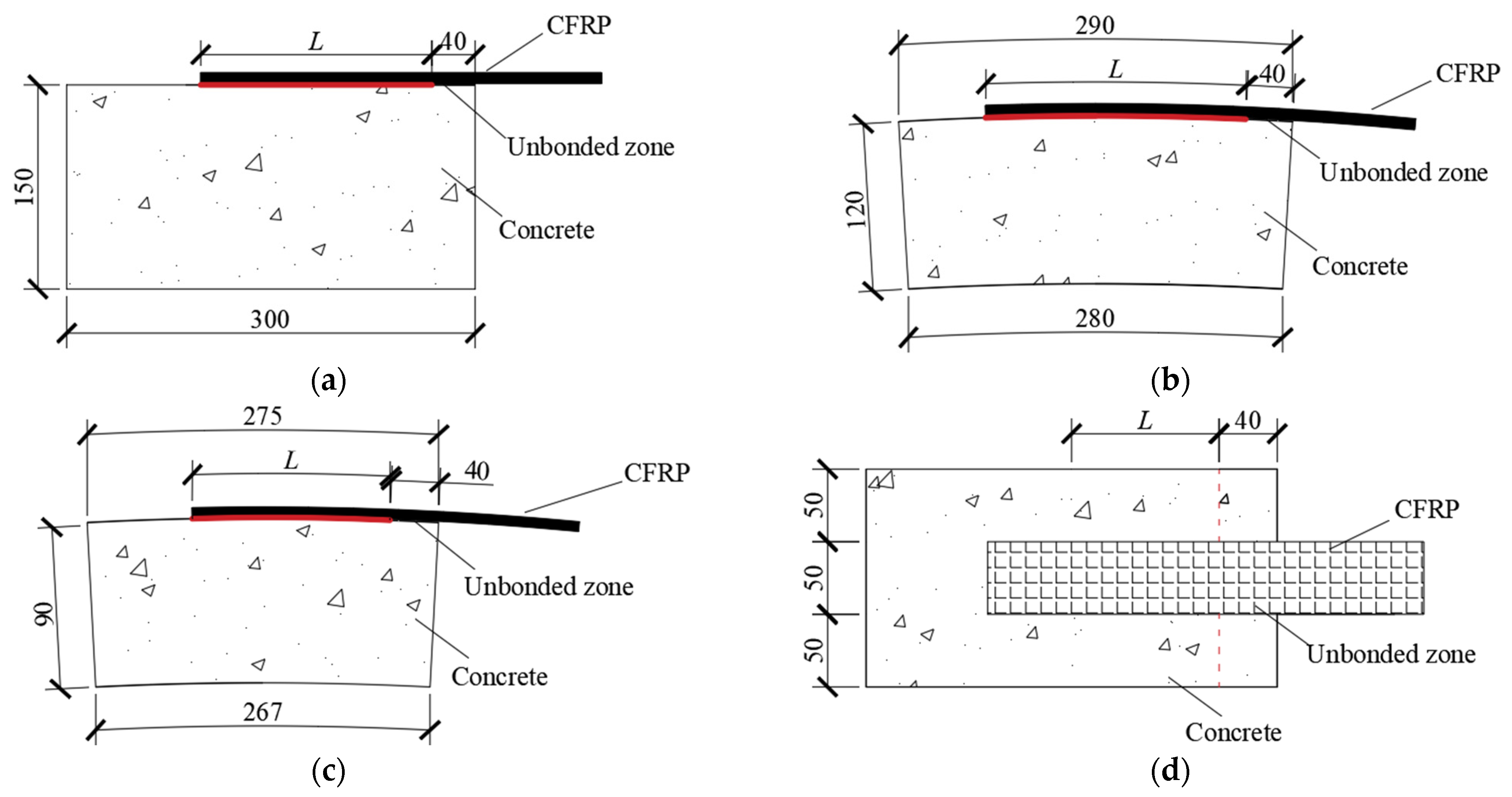
2.1. Specimen’s Design

A total of eighteen groups of single shear bond specimens were designed with different concrete surface curvatures, bond lengths, and CFRP layers. Each group contained three identical specimens. To prevent concrete failure at the loading end of the specimen, an unbonded zone of 40 mm long was reserved away from the loading end [42,43]. The width of all CFRP laminates is 50 mm, and the details of bond specimens are shown in Figure 1. The chosen radius of the reinforced concrete element was 0.8 m and 1.8 m, and the corresponding convex-circular arc curvature was 1/(0.8 m) and 1/(1.8 m), respectively. The specimen with a plane surface was used as a reference. The concrete blocks were designed to different thicknesses for convenience of loading requirements. The letter “L” in Figure 1 represents the bond length. The bond length in this experiment was 80 mm, 120 mm, and 160 mm, respectively. The CFRP was bonded as a layer or two layers to investigate the effect of the CFRP thickness on the bond behavior.

2.2. Material Properties

The designed cube compressive strength of concrete at curing age of 28 day was 55 MPa. Table 1 shows the mix proportion design of concrete with a water–binder ratio of 0.33 used in this experiment. Common Portland cement (52.5 R), river sand, and 5–16 mm nature gravel were used as the raw materials. Accompanied with the specimens for the bonding test, the cubic specimens were fabricated. The cube compressive strength of the concrete was measured using a group of cubic specimens with a dimension of 150 m.
With the aim of applying the CFRP to reinforcing the existing curved beams or concrete pipes using prestressed technics [9,44], high-strength CFRP with a higher modulus of elasticity was selected in this study. The nominal thickness of the CFRP laminate was 0.167 mm. The tested tensile strength, modulus of elasticity, and the ultimate strain of CFRP were 2506 MPa, 245 GPa, and 1.76%, respectively. The tensile strength and the tensile modulus of the adhesive were 43.7 MPa and 2.61 GPa, according to the report of manufacturer.

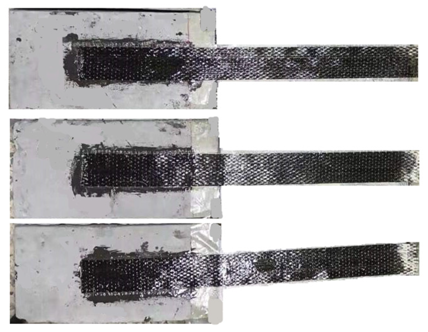
2.3. Preparation of Bonding Specimens

The surfaces of concrete were brushed to remove the surficial mortar until the coarse aggregates were visible and cleaned with a vacuum cleaner. The treated surfaces were saturated with epoxy primer, while the CFRP laminates were also saturated in the epoxy resin. The primer and resin were two-component epoxy, which is composed of part A (base component) and part B (hardener). According to the recommendations of the manufacturer, the primer and resin were made by mixing parts A and B in a mass ratio of 2:1. Next, the saturated CFRP laminate was bonded to the concrete surface. The air in the bonding area was removed using a roller that rolled along the direction of the fibers. The average thickness of the polymer and epoxy was about 1.0 mm. As shown in Figure 2, all bond specimens were cured for 7 days under ambient conditions before testing.

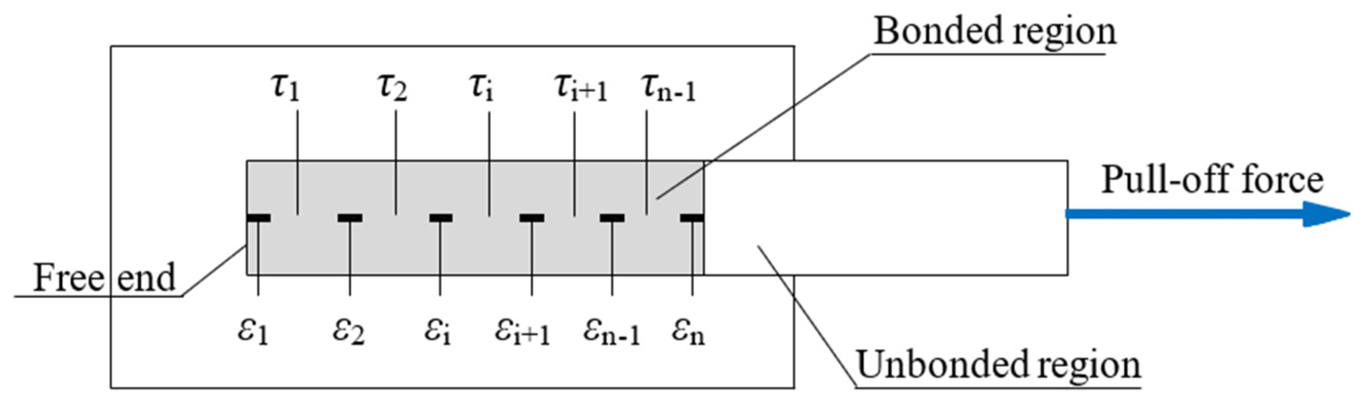
2.4. Single Shear Test Method

The loading device is depicted in Figure 3. The concrete specimen was fixed on the reaction frame, and the CFRP at the loading end was kept in a horizontal state. To obtain the slip of CFRP at the loading end, two linear variable displacement transducers (LVDTs) were arranged on the loading end of the CFRP laminate and concrete block, respectively. Along the CFRP laminate, three to five strain gauges were arranged along the centerline of the CFRP laminate to measure longitudinal strains. For each FRP bond length specimen, the distance of the strain gauges from the loaded end xi is shown in Table 2. The CFRP was gripped by a clamp. This clamp was a flat-plate anchor, which was linked using a steel bolt. The steel bolt was fixed at the end after passing through a hollow hydraulic jack and a load sensor. The clamp could be fixed on the base during the installation, and it could slide in the horizontal direction during loading process. The pull-off force was applied using the hydraulic jack at a rate of 10 N/s, and measured by the load sensor with the accuracy of 1 N. In the process of pull-off loading, the data acquisition system was utilized to collect the test data of displacements, load, and CFRP strains.

3. Results and Analysis

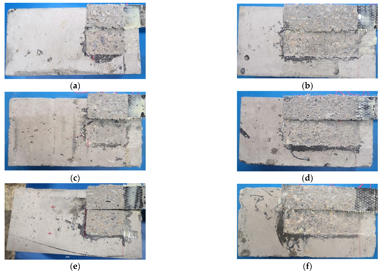
3.1. Failure Pattern

The typical failure of the bonding specimens presented a concrete debonding pattern. It was observed that CFRP was peeled off with a thin layer of concrete, and some coarse aggregates were exposed, as illustrated in Figure 4. For the one-layer CFRP specimen with a plane interface, the debonding failure was brittle when the bond length was 80 mm, as shown in Figure 4a. As the bond length increased, the debonding initiated from the loading end and propagated toward the free end of the CFRP laminate (Figure 4b). The same failure mode was observed for the K2 series specimens, as shown in Figure 4c,d; note that the thickness of the peeling off concrete that was bonded on the CFRP laminate increased compared with the specimens with a plane interface. This indicated that the bond–surface curvature of concrete will affect the CFRP–concrete bond strength. By contrast, the two-layer CFRP laminate specimen had a larger thickness of peeling off concrete on the CFRP compared with the one-layer CFRP laminate specimen, as seen in the comparation in Figure 4a,e,d,f.

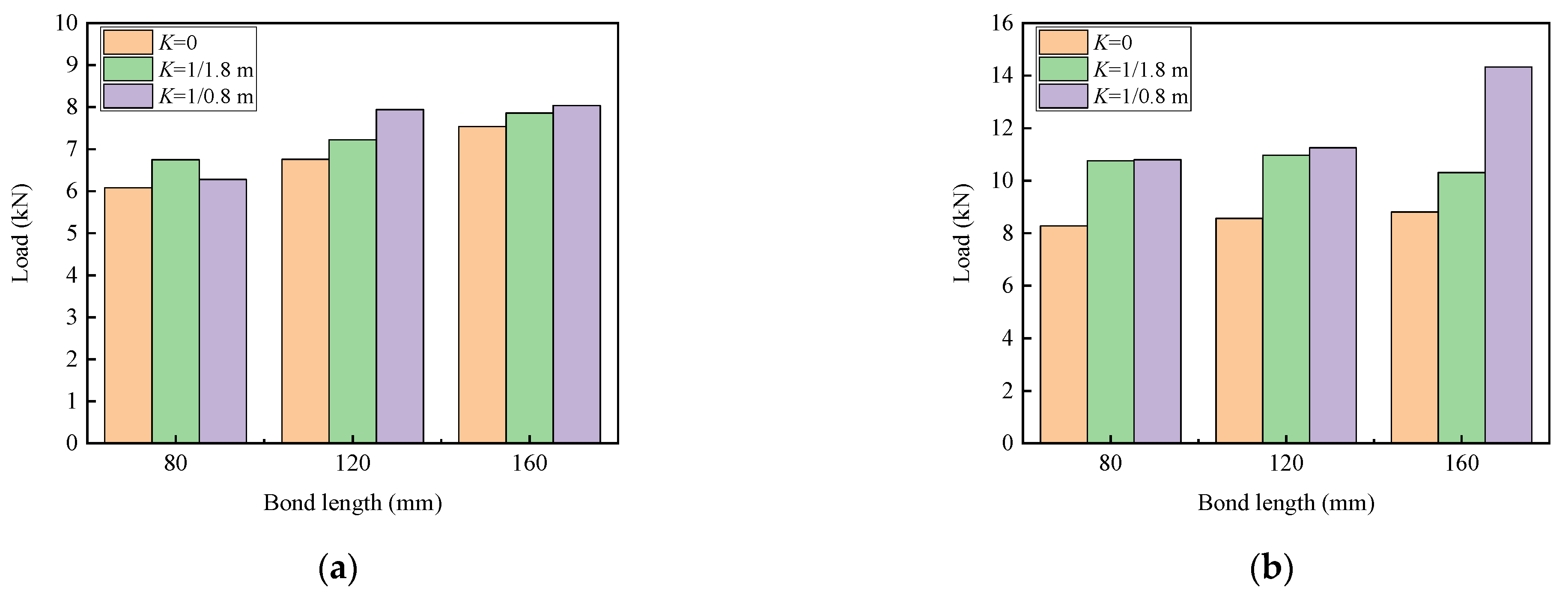
3.2. Ultimate Bearing Capacity

3.2.1. Effect of Bond Length and Layers of CFRP Laminates

Figure 5 shows that the load capacity of the one-layer and two-layer CFRP specimens varies with the bond length. For the one-layer CFRP specimens, the load capacity had an increase of about 15% when the bond length increased from 80 mm to 120 mm, while the load capacity had an increase of about 7% when the bond length ranged between 120 mm and 160 mm. Comparatively, the two-layer CFRP specimen only had a small increase in the load capacity, of about 3%, when the bond length increased from 80 mm to 120 mm; however, the load capacity presented an increase of 8% when the bond length increased from 120 mm to 160 mm.

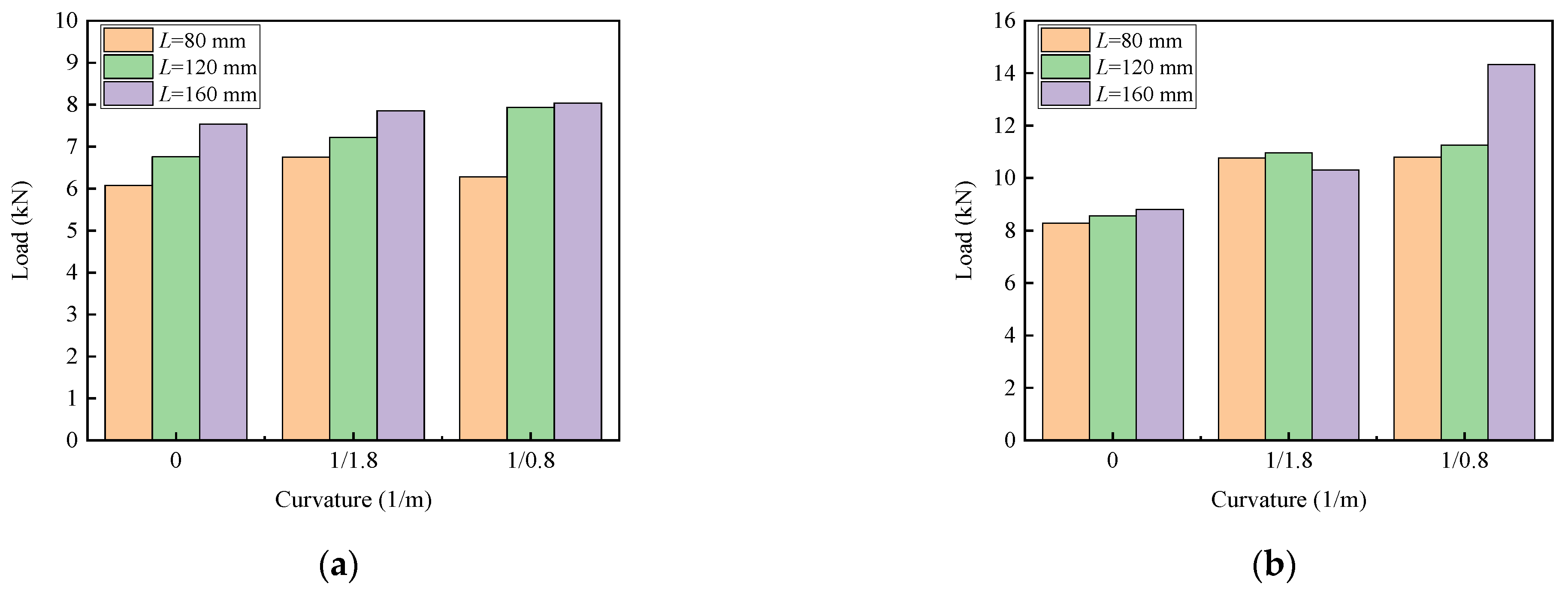
3.2.2. Effect of Bond Surface Curvature of Concrete

Figure 6 exhibits the load capacity of the bond specimens with the interface curvature. Generally, the load capacity of the bond specimens increased with the interface curvature. With the increase in the interface curvature from 0 to 1/0.8 m, the average load capacity of the one-layer and two-layer CFRP specimens had an increase of about 9% and 42%, respectively. This indicates that the two-layer CFRP specimens had a much higher load capacity than the one-layer CFRP specimens. This can be explained using the bearing condition of a circular arc infinitesimal element of CFRP, as shown in Figure 7. The tangential force will create a component pressure on the convex-curved interface along the normal direction, which will provide a confinement to the peeling off of CFRP laminate during the loading process.
The bond stress and normal stress are assumed to be uniform along the convex-circular arc infinitesimal element. Based on the force equilibrium of the infinitesimal element, the equation along the x and y axis can be presented by:
( σ f + d σ f ) t f cos d θ 2 σ f t f cos d θ 2 = τ R d θ
( σ f + d σ f ) t f sin d θ 2 + σ f t f sin d θ 2 = σ n R d θ
By substituting the equivalence infinitesimal and ignoring the infinitesimal of the higher order, the equations can be simplified as follows:
d σ f R d θ = τ t f
σ n σ f t f R
where τ is the interfacial bond stress, R is the radius of curvature, σf and σn are the axial stress of CFRP and the normal stress on the convex-circular arc interface, respectively, and tf is the thickness of the CFRP.
As observed from Equation (4), the normal stress σn is inversely proportional to the radius of curvature R. The normal stress on the convex-circular arc interface will increase with the decrease in the radius of curvature. This is the reason why the load capacity changes with the interface curvature. The result is similar to the bond characteristics of FRP-to-concrete under pressure in that the bond capacity between the CFRP and concrete increased with the lateral pressure [45]. Meanwhile, it is also similar to the mechanism of hybrid bonding FRP, which is achieved through applying lateral anchor force on the CFRP [18].

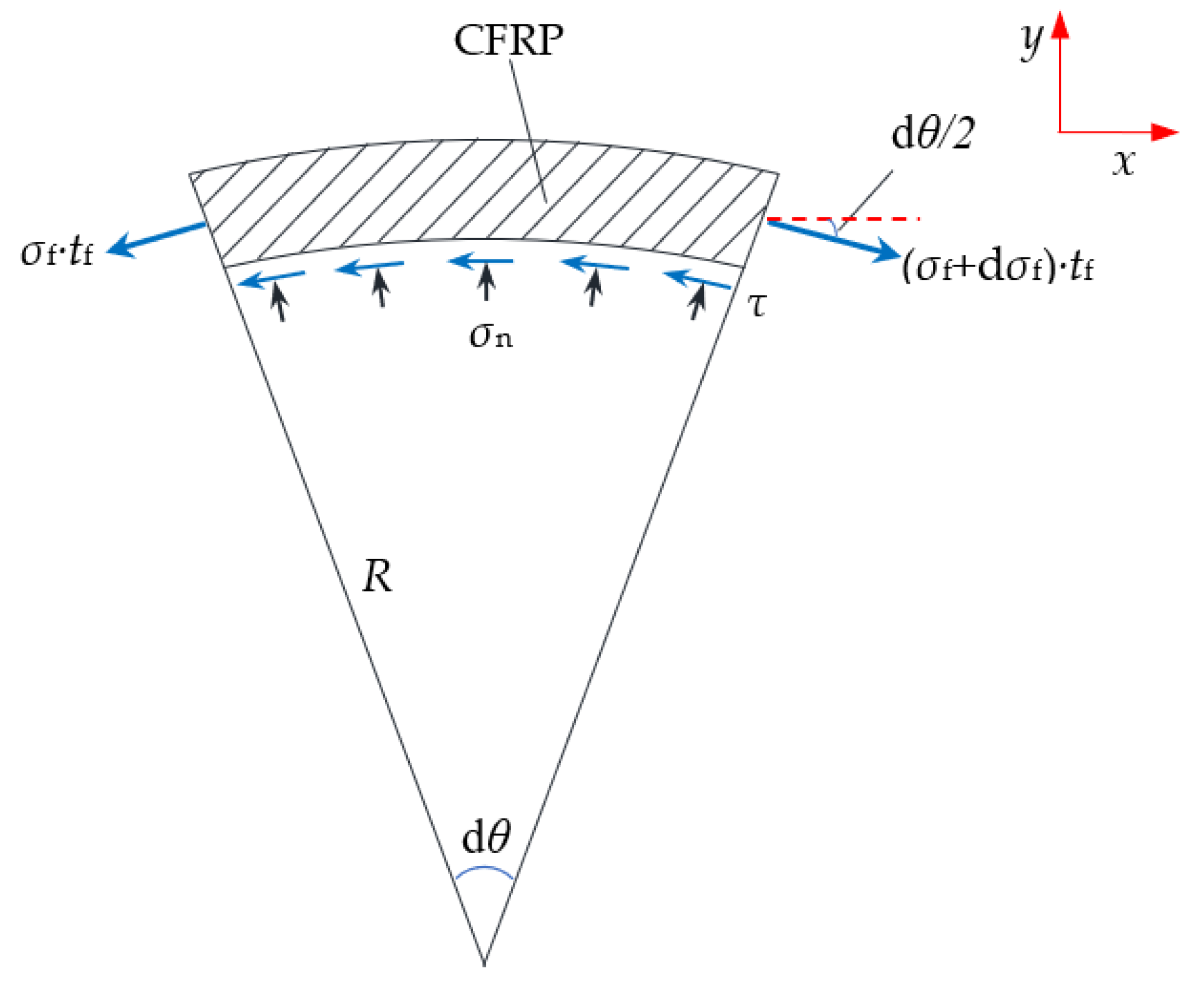
3.2.3. Calculation Model
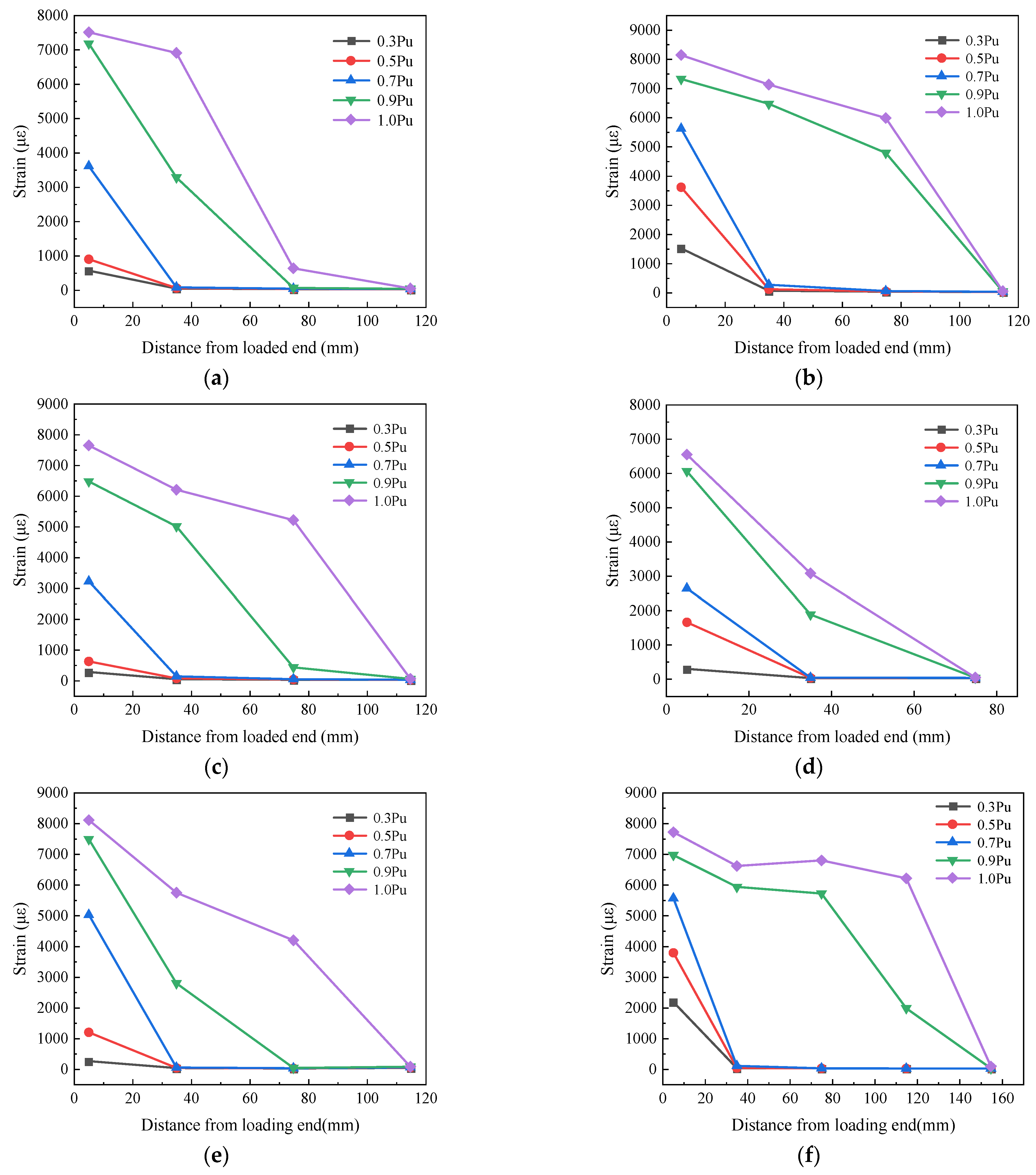
Based on the load capacity formula of an FRP-concrete bonded joint proposed by Chen and Teng [22], the calculation formula of the interfacial debonding bearing capacity is given considering the influence of the interface curvature.
P u = α β L β w β K b f L e f c
β w = 2 b f / b c 1 + b f / b c
L e = E f / t f f c
β K = 1 + γ K
where βL is a coefficient of the effective bond length, βL = 1 if LLe, βL = sin(πL/2Le) if L < Le; βw is a coefficient of the width ratio of CFRP to concrete; βK is a coefficient of the interface curvature, which can be determined from the test results with different interface curvatures K, K = 0 when the bonding surface of concrete is plane; γ is a curvature influence coefficient, γ = 0.07 and γ = 0.25 for one-layer CFRP and two-layer CFRP, respectively; bf and bc are the widths of the CFRP laminate and concrete block, respectively; Le is the effective bond length; Ef and tf are the elastic modulus and thickness of the CFRP; f c is the cylinder compressive strength of concrete, f c = 0 . 79 f cu , f cu is the cubic compressive strength; α is a constant determined by the regression of the test data, α = 0.22 obtained in this test.
The bond capacity of the CFRP–concrete with a curved interface can be calculated using Equation (5). The calculated values and experimental results of the load capacity of each group specimen are summarized in Table 3. The tested load capacity of each group was the average of the three identical specimens. The overall average ratio of the calculated experimental results is 0.997 with a standard deviation of 0.099. The comparison results show that Equation (5) has sufficient accuracy for predicting the load capacity with a convex-circular arc surface, as well as a flat surface. Because the bond capacity of the CFRP–concrete interface is affected by many more factors, the machine language algorithm could also be adopted for future research works to improve the prediction accuracy and to provide a more comprehensive understanding of the influencing parameters [46,47,48,49].

3.3. CFRP Strains

Figure 8 shows the strains along the CFRP laminate for some of the bond specimens at different loading levels, which are equal to 0.3, 0.5, 0.7, 0.9, or 1.0 of the ultimate load (Pu). When the load is lower than 0.7 Pu, the strain of the CFRP reaches the maximum at the loading end and gradually decreases to the free end. With the further increase in the loads, the strain of the CFRP near the loading end gradually increases. This indicates that the bond stress is gradually transferred from the loading end to the free end. According to Equation (7), the calculated effective bond length is about 75 mm and 105 mm for the one-layer and two-layer CFRP specimens, respectively. The strain of the free end slightly changes during the loading process. This is because the actual bond length exceeds the effective bond length, and the strain of the CFRP increases within a limit length.
From Figure 8a–c, the two-layer CFRP specimens create the CFRP strain ranging between 7500 με and 8200 με at the loading end under the maximum load, and a longer length of strain distribution can be found on the specimens with a curved interface. This indicates that the effective bond length will increase because of the normal compress on the bonding interface. As the slope of the curve is proportional to the local bond stress, the slope of the curve near the free end increases when the load exceeds 0.7 Pu, which expresses the transferring process of the bond stress to the free end. Meanwhile, the strain of the CFRP bonded to concrete with a curved interface is higher than that of the specimen with a plane interface at the same position. This indicates that the increase in concrete curvature improves the transfer ability and ductility of the bond load.
From Figure 8d–f, the one-layer CFRP specimens show that the CFRP strain distribution varies with the bond length. When the bond length is 80 mm, the maximum strain of the CFRP at the ultimate load is about 6500 με; as shown in Figure 8d, the strain is almost linearly decreased along the CFRP bond length at each load level. This indicates an approximately uniform bond stress along the bond length. When the bond length increases to 120 mm, the maximum strain of CFRP is about 7500 με at 0.9 Pu, and the effective bond length is about 77 mm, as shown in Figure 8e, which is close to the calculated result of 80 mm. When the bond length increases to 160 mm, the maximum strain of CFRP slightly changes, while a strain plateau appears on the curves, as shown in Figure 8f; this indicates that the effective bond zone is shifted towards the free end of the CFRP. This explains why the bearing capacity remains almost constant when the bond length exceeds the effective bond length.

3.4. Bond–Slip Constitutive Model

The local bond–slip constitutive relationship between CFRP and concrete is the basis for determining the interfacial performance. The local bond slip could be obtained using the CFRP strain measured in the experiment, according to the method in the existing literature [50,51]. The CFRP laminate is discretized into multiple elements, as shown in Figure 9.
Assuming that the CFRP is a linear elastic material, the average bond stress between two adjacent strain gauges is calculated according to Equation (9):
τ i = ( ε f , i + 1 ε f , i ) t f E f Δ x i   ( i = 1 , 2 n 1 )
where εf,i is the value of the ith strain gauge; Δxi is the distance between the ith and (i + 1)th strain gauges.
The local slip is the difference between the elongation of the CFRP and the equivalent section elongation of the concrete and adhesive layer.
s i = s i 1 + ( δ f , i δ m , i )   ( i = 1 , 2 n 1 ; s 0 = 0 )
δ f , i = ε f , i + 1 + ε f , i 2 Δ x i
δ m , i = ε m , i + ε m , i + 1 2 Δ x i
ε m , i = P m , i - 1 2 τ i - 1 b f Δ x i - 1 A m E m ( i = 2 , 3 , n 1 )
ε m , 1 = P load A m E m  
P m , i = ε m , i A m E m
where δ f , i is the elongation of the CFRP at the section i; δ m , i is the elongation of the equivalent cross-section at the section i; ε m , i is the strain of the equivalent cross-section at the section i; P load is the load at the loading end of CFRP; P m , i is the load on the equivalent element i; A m E m is the equivalent cross-section stiffness.
According to Equations (9) and (10), the local bond stress and slip could be calculated, and the bond–slip curves of some specimens are plotted in Figure 10.
Overall, the bond–slip curve is composed of the ascending and descending parts. The elastic stage, the softening stripping stage, and the complete stripping stage are the important stages for these curves [52,53,54,55,56]. Referring to a two-stage model, which included the ascending stage and descending stage, that was adopted to simulate the bond–slip relationship of steel bars in concrete confined with stirrups under freeze–thaw cycles [57]. The bond–slip relationship can be expressed using the equations in Table 4, in which A and B are constants determined by the test results, A = 0.8 and B = 3, which are obtained through nonlinear curve fitting in this study for all groups of specimens.
Figure 10. Local bond–slip curves. (a) K1L120P1; (b) K1L160P1; (c) K2L80P1; (d) K2L160P2; (e) K3L120P1; (f) K3L160P2 [58,59,60].
Buildings 13 03077 g010
As presented in Table 4, three existing bond–slip models developed by Monti et al. [58], Nakaba et al. [59], and Savioa et al. [60] were modified to make them applicable to the bond strength of CFRP bonded to the curved concrete surface, in which β w and β K can be obtained using Equation (6) and (8). The tensile strength ft and compressive strength f c   of concrete were related to the cube compressive strength of concrete, according to [30]: f t = 0.395 ( f cu ) 0.55 and f c = 0.76 f cu .
The bond–slip model proposed in this study was compared with the three existing bond–slip models, as shown in Figure 10. This shows that the model proposed in this study and Monti et al.’s model is closer to the test results than the other two models for the ascending parts. On the other hand, for the descending parts, the model proposed in this study is closest to the test results.

4. Conclusions

This paper presents the experimental work of the bond behavior between CFRP and concrete with a convex-circular arc surface through single shear tests. Fifty-four pull-off specimens were tested, considering the influence of the concrete interface curvature, the bond length, and the CFRP layers. The following conclusions can be derived from the results of this study:
(1)
The peeling of CFRP was the main failure pattern of the bonding specimens. With the increase in the concrete interface curvature from 0 to 1/(0.8 m), the bond capacity had an increase of about 9% for the one-layer CFRP specimens, while it had an increase of about 42% for the two-layer CFRP specimens.
(2)
Considering the influence of the concrete interface curvature, the calculation formula of the bond capacity of CFRP to concrete is proposed, and the curvature influence coefficient is obtained through the regression of the experimental data. The applicability of the formula was verified by comparing the calculated values with the experimental results.
(3)
The variation in the CFRP strain during the loading process was analyzed. The local bond–slip curve of each specimen was calculated through the differential analysis of the tested CFRP strains. A two-stage model is proposed for simulating the interface relationship. In comparison with the three existing bond–slip models, the model proposed in this study is closest to the test results.
(4)
It should be noted that the scope of the present research has been limited to CFRP–concrete bonded specimens with a convex-circular arc surface as well as a flat surface. The present work can be applied to externally bonded CFRP laminates on strengthening concrete pipes and other concrete structural members with a convex curved surface. Further efforts can be carried out on the bond behavior of CFRP to concrete with more complex curved interfaces.

Author Contributions

Methodology, F.Q. and S.Z.; investigation and writing—original draft, H.W. and Q.M.; writing—review and editing, F.Q. and D.F.; funding acquisition, S.Z. and H.L. All authors have read and agreed to the published version of the manuscript.

Funding

This research was funded by the CSCEC Technology Research and Development Project, China (grant number CSCEC-2021-Z-24) and Key Scientific Research Projects of Universities in Henan Province, China (grant number 23A570007).

Data Availability Statement

The data presented in this study are available on request from the corresponding author. The data are not publicly available due to privacy.

Conflicts of Interest

Authors Hailu Lu, Dakuo Feng and Qingxin Meng were employed by the company China Construction Seventh Engineering Bureau Co., Ltd., China. The remaining authors declare that the research was conducted in the absence of any commercial or financial relationships that could be construed as a potential conflict of interest.

References

  1. Gravina, R.J.; Smith, S.T. Flexural behaviour of indeterminate concrete beams reinforced with FRP bars. Eng. Struct. 2008, 30, 2370–2380. [Google Scholar] [CrossRef]
  2. Li, F.; Zhang, J.; Hou, P.; Qu, F. Experimental study on reinforcing corroded reinforced concrete beams with adhesive steel plates. Concrete 2013, 35, 9–12. [Google Scholar]
  3. Qu, F.; Meng, J.; Li, F. Numerical analysis of corroded reinforced concrete reinforced by adhesive steel reinforcement. Concrete 2016, 38, 8–11. [Google Scholar]
  4. Isleem, H.F.; Wang, D.Y.; Wang, Z.Y. A new numerical model for polymer-confined rectangular concrete columns. Proc. Inst. Civ. Eng. Struct. Build. 2019, 172, 528–544. [Google Scholar] [CrossRef]
  5. Isleem, H.F.; Wang, Z.Y.; Wang, D.Y.; Smith, S.T. Monotonic and cyclic axial compressive behavior of CFRP-confined rectangular RC columns. J. Compos. Constr. 2018, 2, 04018023. [Google Scholar] [CrossRef]
  6. Tahir, M.; Wang, Z.Y.; Ali, K.M.; Isleem, H.F. Shear behavior of concrete beams reinforced with CFRP laminate strip stirrups using wet-layup technique. Structures 2019, 22, 43–52. [Google Scholar] [CrossRef]
  7. Razaqpur, A.G.; Lamberti, M.; Ascione, F. Debonding evolution in nonlinear FRP-retrofitted RC beams with cohesive interface. Compos. Struct. 2020, 236, 111858. [Google Scholar] [CrossRef]
  8. Isleem, H.F.; Wang, D.Y.; Wang, Z.Y. Modeling the axial compressive stress-strain behavior of CFRP-confined rectangular RC columns under monotonic and cyclic loading. Compos. Struct. 2018, 185, 229–240. [Google Scholar] [CrossRef]
  9. Wang, H.; Li, C.; Song, S.; Wang, Y.; Meng, Q.; Li, F. Flexural performance of cracked reinforced concrete beams strengthened with prestressed CFRP laminates under repeated loads. Buildings 2023, 13, 2115. [Google Scholar] [CrossRef]
  10. Smith, S.T.; Teng, J. Shear-bending interaction in debonding failures of FRP-plated RC beams. Adv. Struct. Eng. 2003, 6, 183–199. [Google Scholar] [CrossRef]
  11. Cao, S.; Chen, J.; Pan, J.; Sun, N. ESPI measurement of bond-slip relationships of FRP-concrete interface. J. Compos. Constr. 2007, 11, 149–160. [Google Scholar] [CrossRef]
  12. Aydin, H.; Gravina, R.J.; Visintin, P. A partial-interaction approach for extracting FRP-to-concrete bond characteristics from environmentally loaded flexural tests. Compos. Part B Eng. 2018, 132, 214–228. [Google Scholar] [CrossRef]
  13. Monti, G.; Liotta, M. Tests and design equations for FRP-strengthening in shear. Constr. Build. Mater. 2007, 21, 799–809. [Google Scholar] [CrossRef]
  14. Colotti, V. Effectiveness factors for bond strength in FRP shear-strengthened RC beams. Mater. Struct. 2016, 49, 5031–5049. [Google Scholar] [CrossRef]
  15. Razaqpur, A.G.; Lamberti, M.; Ascione, F. A nonlinear semi-analytical model for predicting debonding of FRP laminates from RC beams subjected to uniform or concentrated load. Constr. Build. Mater. 2020, 233, 117838. [Google Scholar] [CrossRef]
  16. Ascione, F.; Lamberti, M.; Napoli, A.; Razaqpur, A.G.; Realfonzo, R. Modeling SRP-concrete interfacial bond behavior and strength. Eng. Struct. 2019, 187, 220–230. [Google Scholar] [CrossRef]
  17. Lamberti, M.; Ascione, F.; Napoli, A.; Razaqpur, G.; Realfonzo, R. Nonlinear analytical procedure for predicting debonding of laminate from substrate subjected to monotonic or cyclic load. Materials 2022, 15, 8690. [Google Scholar] [CrossRef] [PubMed]
  18. Liu, G.; Wang, Y.; Qu, F.; Guo, X.; Li, Y.; Cheng, S. Bonded behavior of hybrid-bonded CFRP to heat-damaged concrete interface. Buildings 2023, 13, 2736. [Google Scholar] [CrossRef]
  19. Teng, J.; Smith, S.T.; Yao, J.; Chen, J. Intermediate crack-induced debonding in RC beams and slabs. Constr. Build. Mater. 2003, 17, 447–462. [Google Scholar] [CrossRef]
  20. Kabir, M.I.; Shrestha, R.; Samali, B. Effects of applied environmental conditions on the pull-out strengths of CFRP-concrete bond. Constr. Build. Mater. 2016, 114, 817–830. [Google Scholar] [CrossRef]
  21. Van Gemert, D. Force transfer in epoxy-bonded steel-concrete joints. Int. J. Adhes. Adhes. 1980, 1, 67–72. [Google Scholar] [CrossRef]
  22. Chen, J.; Teng, J. Anchorage strength models for FRP and steel plates bonded to concrete. J. Struct. Eng. 2001, 127, 784–791. [Google Scholar] [CrossRef]
  23. Bizindavyi, L.; Neale, K.W. Transfer lengths and bond strengths for composites bonded to concrete. J. Compos. Constr. 1999, 3, 153–160. [Google Scholar] [CrossRef]
  24. Jawdhari, A.; Semendary, A.; Fam, A.; Khoury, I.; Steinberg, E. Bond characteristics of CFRP rod panels adhered to concrete under bending effects. J. Compos. Constr. 2019, 23, 04018077. [Google Scholar] [CrossRef]
  25. Liu, K.; Wu, Y. Analytical identification of bond-slip relationship of EB-FRP joints. Compos. Part B Eng. 2012, 43, 1955–1963. [Google Scholar] [CrossRef]
  26. Ceroni, F.; Garofano, A.; Pecce, M. Bond tests on tuff elements externally bonded with FRP materials. Mater. Struct. 2015, 48, 2093–2110. [Google Scholar] [CrossRef]
  27. Yang, Y.; Yue, Q.; Hu, Y. Experimental study on bond performance between carbon fiber laminates and concrete. J. Build. Struct. 2001, 22, 36–42. [Google Scholar]
  28. Moghaddas, A.; Mostofinejad, D.; Saljoughian, A.; Ilia, E. An empirical FRP-concrete bond-slip model for externally-bonded reinforcement on grooves. Constr. Build. Mater. 2021, 281, 122575. [Google Scholar] [CrossRef]
  29. Wu, Y.; Zhou, Z.; Yang, Q.; Chen, W. On shear bond strength of FRP-concrete structures. Eng. Struct. 2010, 32, 897–905. [Google Scholar] [CrossRef]
  30. Lu, X.; Teng, J.; Ye, L.; Jiang, J. Bond–slip models for FRP laminates/plates bonded to concrete. Eng. Struct. 2005, 27, 920–937. [Google Scholar] [CrossRef]
  31. Liu, G.; Qu, F.; Zhao, S.; Zhang, H. Experimental study on the adhesion properties of CFRP fabric to post-temperature concrete. J. Build. Struct. 2019, 40, 156–162. [Google Scholar]
  32. Leone, M.; Matthys, S.; Aiello, M.A. Effect of elevated service temperature on bond between FRP EBR systems and concrete. Compos. Part B Eng. 2009, 40, 85–93. [Google Scholar] [CrossRef]
  33. Jia, D.; Gao, W.; Duan, D.; Yang, J.; Dai, J. Full-range behavior of FRP-to-concrete bonded joints subjected to combined effects of loading and temperature variation. Eng. Fract. Mech. 2021, 254, 107928. [Google Scholar] [CrossRef]
  34. Arruda, M.R.T.; Firmo, J.P.; Correia, J.R.; Tiago, C. Numerical modelling of the bond between concrete and CFRP laminates at elevated temperatures. Eng. Struct. 2016, 110, 233–243. [Google Scholar] [CrossRef]
  35. Li, Y.; Chen, J.; Yang, Z.; Esmaeeli, E.; Sha, W.; Huang, Y. Effects of concrete heterogeneity on FRP-concrete bond behaviour: Experimental and mesoscale numerical studies. Compos. Struct. 2021, 275, 114436. [Google Scholar] [CrossRef]
  36. Li, W.; Yan, Z.; Cao, Z.; Pan, J. Effect of concrete surface roughness on the bonding performance between the CFRP and concrete. J. Shenzhen Univ. Sci. Eng. 2007, 24, 13–17. [Google Scholar]
  37. Pan, J.; Leung, C.K. Effect of concrete composition on FRP/concrete bond capacity. J. Compos. Constr. 2007, 11, 611–618. [Google Scholar] [CrossRef]
  38. De Lorenzis, L.; Teng, J.G. Near-surface mounted FRP reinforcement: An emerging technique for strengthening structures. Compos. Part B Eng. 2007, 38, 119–143. [Google Scholar] [CrossRef]
  39. Qu, F.; Xu, Z.; Yu, T.; Song, K. Experimental study on bonding performance of embedded carbon fiber reinforced composite panel-concrete interface. J. N. China Univ. Water Resour. Electric Power (Nat. Sci. Ed.) 2020, 41, 65–69. [Google Scholar]
  40. Zhai, K.; Fang, H.; Fu, B.; Wang, F.; Hu, B. Mechanical response of externally bonded CFRP on repair of PCCPs with broken wires under internal water pressure. Constr. Build. Mater. 2020, 239, 117878. [Google Scholar] [CrossRef]
  41. Zhai, K.; Fang, H.; Guo, C.; Ni, P.; Wu, H.; Wang, F. Full-scale experiment and numerical simulation of prestressed concrete cylinder pipe with broken wires strengthened by prestressed CFRP. Tunn. Undergr. Space Technol. 2021, 115, 104021. [Google Scholar] [CrossRef]
  42. Coronado, C.A.; Lopez, M.M. Damage approach for the prediction of debonding failure on concrete elements strengthened with FRP. J. Compos. Constr. 2007, 11, 391–400. [Google Scholar] [CrossRef]
  43. Mazzotti, C.; Savoia, M.; Ferracuti, B. An experimental study on delamination of FRP plates bonded to concrete. Constr. Build. Mater. 2008, 22, 1409–1421. [Google Scholar] [CrossRef]
  44. Liu, G.; Li, B.; Bao, J.; Cheng, S.; Meng, Q.; Zhao, S. Case study on prestressed CFRP plates applied for strengthening hollow-section beam removed from an old bridge. Polymers 2023, 15, 549. [Google Scholar] [CrossRef] [PubMed]
  45. Gao, L.; Zhang, F.; Liu, J.; Lu, X. Whole-process bond characteristics of FRP-to-concrete joint under pressure. KSCE J. Civ. Eng. 2018, 22, 5114–5122. [Google Scholar] [CrossRef]
  46. Feng, D.; Liu, Z.; Wang, X.; Chen, Y.; Chang, J.; Wei, D.; Jiang, Z. Machine learning-based compressive strength prediction for concrete: An adaptive boosting approach. Constr. Build. Mater. 2020, 230, 117000. [Google Scholar] [CrossRef]
  47. Jia, Z.; Wang, W.; Zhang, J.; Li, H. Contact high-temperature strain automatic calibration and precision compensation research. J. Artif. Intell. Technol. 2022, 2, 69–76. [Google Scholar]
  48. Du, H.; Du, S.; Li, W. Probabilistic time series forecasting with deep non-linear state space models. CAAI Trans. Intell. Technol. 2023, 8, 3–13. [Google Scholar] [CrossRef]
  49. Isleem, H.F.; Peng, F.; Tayeh, B.A. Confinement model for LRS FRP-confined concrete using conventional regression and artificial neural network techniques. Compos. Struct. 2022, 279, 114779. [Google Scholar] [CrossRef]
  50. Dai, J.; Ueda, T.; Sato, Y. Development of the nonlinear bond stress-slip model of fiber reinforced plastics laminate-concrete interfaces with a simple method. J. Compos. Constr. 2005, 9, 52–62. [Google Scholar] [CrossRef]
  51. Ferracuti, B.; Savoia, M.; Mazzotti, C. Interface law for FRP–concrete delamination. Compos. Struct. 2007, 80, 523–531. [Google Scholar] [CrossRef]
  52. Biscaia, H.; Chastre, C.; Silva, M. Bond-slip model for FRP-to-concrete bonded joints under external compression. Compos. Part B Eng. 2015, 80, 246–259. [Google Scholar] [CrossRef]
  53. Yuan, H.; Teng, J.; Seracino, R.; Wu, Z.; Yao, J. Full-range behavior of FRP-to-concrete bonded joints. Eng. Struct. 2004, 26, 553. [Google Scholar] [CrossRef]
  54. Au, C.; Büyüköztürk, O. Debonding of FRP plated concrete: A tri-layer fracture treatment. Eng. Fract. Mech. 2006, 73, 348–365. [Google Scholar] [CrossRef]
  55. Wu, Z.; Yuan, H.; Niu, H. Stress transfer and fracture propagation in different kinds of adhesive joints. J. Eng. Mech. 2002, 128, 562–573. [Google Scholar] [CrossRef]
  56. Zhou, Y.; Wu, Y.; Yun, Y. Analytical modeling of the bond-slip relationship at FRP-concrete interfaces for adhesively-bonded joints. Compos. Part B Eng. 2010, 41, 423–433. [Google Scholar] [CrossRef]
  57. Liu, G.; Dou, X.; Qu, F.; Shang, P.; Zhao, S. Bond behavior of steel bars in concrete confined with stirrups under freeze–thaw cycles. Materials. 2022, 15, 7152. [Google Scholar] [CrossRef]
  58. Monti, G.; Renzelli, M.; Luciani, P. FRP adhesion in uncracked and cracked concrete zones. In Proceedings of the 6th International Symposium on FRP Reinforcement for Concrete Structures, Singapore, 8–10 July 2003. [Google Scholar]
  59. Nakaba, K.; Kanakubo, T.; Furuta, T.; Yoshizawa, H. Bond behavior between fiber-reinforced polymer laminates and concrete. ACI Struct. J. 2001, 98, 359–367. [Google Scholar]
  60. Savoia, M.; Ferracuti, B.; Mazzotti, C. Non-linear bond-slip law for FRP-concrete interface. In Proceedings of the 6th International Symposium on FRP Reinforcement for Concrete Structures, Singapore, 8–10 July 2003. [Google Scholar]
Figure 1. Schematic diagram of bond specimens. (a) side view of K1 series; (b) side view of K2 series; (c) side view of K3 series; (d) plan view of all series.
Buildings 13 03077 g001
Figure 2. View of some bonding specimens.
Buildings 13 03077 g002
Figure 3. View of single shear test: (a) schematic diagram (K3 series specimen); (b) test picture.
Buildings 13 03077 g003
Figure 4. CFRP debonding failure of the specimens: (a) K1L80P1; (b) K1L160P1; (c) K2L80P1; (d) K2L160P1; (e) K1L80P2; (f) K3L160P2.
Buildings 13 03077 g004
Figure 5. Effect of bond length on load capacity: (a) one-layer CFRP; (b) two-layer CFRP.
Buildings 13 03077 g005
Figure 6. Effect of circular arc curvature on load capacity: (a) one-layer CFRP; (b) two-layer CFRP.
Buildings 13 03077 g006
Figure 7. Load condition per unit width of an infinitesimal element of CFRP with a convex-circular arc interface.
Buildings 13 03077 g007
Figure 8. CFRP strains along its length: (a) K1L120P2; (b) K2L120P2; (c) K3L120P2; (d) K3L80P1; (e) K3L120P1; (f) K3L160P1.
Buildings 13 03077 g008
Figure 9. Schematic diagram of strain and bond stress.
Buildings 13 03077 g009
Table 1. Mix proportion of concrete (kg/m3).
WaterCementFly AshFine AggregateCoarse AggregateWater Reducer
1413606469811886.36
Table 2. Distance x (mm) of strain gauges from the loading end.
Bond Length (mm)x1x2x3x4x5
8053575--
12053575115-
16053575115155
Table 3. Comparison of tested with calculated values of the load capacity.
Group No.fcu
(N/mm2)
K
(1/m)
tf
(mm)
L
(mm)
Test Result (kN)Calculated Value (kN)Calculated/Test Result
K1L80P166.7100.167806.086.701.10
K2L80P166.711/1.80.167806.756.961.03
K3L80P166.711/0.80.167806.287.291.16
K1L120P151.6200.1671206.766.290.93
K2L120P151.621/1.80.1671207.226.530.90
K3L120P151.621/0.80.1671207.946.840.86
K1L160P169.1300.1671607.546.760.90
K2L160P169.131/1.80.1671607.867.030.89
K3L160P169.131/0.80.1671608.047.350.91
K1L80P269.1300.334808.288.891.07
K2L80P269.131/1.80.3348010.7610.130.94
K3L80P269.131/0.80.3348010.8011.671.08
K1L120P269.1300.3341208.569.561.12
K2L120P269.131/1.80.33412010.9710.890.99
K3L120P269.131/0.80.33412011.2612.551.11
K1L160P261.2000.3341608.819.281.05
K2L160P261.201/1.80.33416010.3110.571.02
K3L160P261.201/0.80.33416014.3312.180.85
Note: In the group No. of this table, the letter K represents the concrete surface curvature, the letter L denotes the bond length, and the letter P represents the layer of CFRP.
Table 4. Bond–slip models.
Bond–Slip ModelAscending Branch
s s 0
Descending Branch
s > s 0
𝜏max𝑠0𝑠u
Present model τ max ( s s 0 ) A τ max s s 0 B ( s s 0 1 ) 2 + s s 0 1.87 β k β w f t 0.0195 β w f t -
Monti et al. [58] τ max s s 0 τ max s u s s u s 0 1.87 β k β w f t 0.0195 β w f t 0.616 β w 2 f t τ max
Nakaba et al. [59] τ max ( s s 0 ) [ 3 / ( 2 + ( s s 0 ) 3 ) ] 3.5 β k f c 0.19 0.065-
Savioa et al. [60] τ max ( s s 0 ) [ 2.86 / ( 1.86 + ( s s 0 ) 2.86 ) ] 3.5 β k f c 0.19 0.051-
Disclaimer/Publisher’s Note: The statements, opinions and data contained in all publications are solely those of the individual author(s) and contributor(s) and not of MDPI and/or the editor(s). MDPI and/or the editor(s) disclaim responsibility for any injury to people or property resulting from any ideas, methods, instructions or products referred to in the content.

