Article

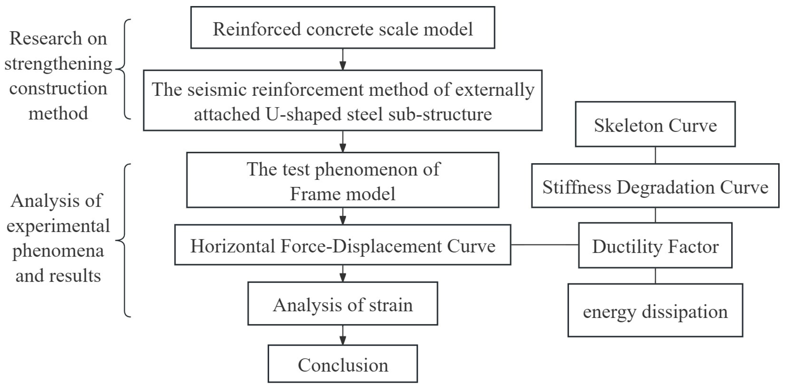
Research on Reinforcement Technology of Existing Frame Structure with Externally Attached U-Shaped Steel Plate Sub-Structure

College of Civil and Transportation Engineering, Shenzhen University, Shenzhen 518060, China
*
Author to whom correspondence should be addressed.
Buildings 2023, 13(12), 3058; https://doi.org/10.3390/buildings13123058
Submission received: 20 October 2023 / Revised: 15 November 2023 / Accepted: 20 November 2023 / Published: 8 December 2023
(This article belongs to the Section Building Structures)

Abstract

:
With the improvement of building technical requirements and the updating of standards, the demand for the reinforcement of existing buildings is increasing. In order to solve the problem regarding the low economic applicability of the traditional seismic retrofit method, this paper proposes a seismic retrofit method for an externally attached U-shaped steel plate sub-structure that follows the concept of “reinforcing while using”, is composed of a U-shaped steel plate and herringbone channel steel, and can meet the needs of multiple retrofits. Based on the results of a pseudo-static test, the mechanical properties of one unreinforced frame and three reinforced frames with different specifications for the U-shaped steel plate sub-structure were comparatively studied, and the effectiveness and rationality of the reinforcement method were analyzed. The results show that the externally attached U-shaped steel plate sub-structure has good deformation and energy dissipation capacity and can effectively improve the horizontal bearing capacity of an existing frame without changing the original failure mode. The bearing capacity of the three reinforced frames was 1.43, 1.89, and 2.57 times that of the unreinforced specimen. The initial lateral stiffness of the frame also increased significantly, namely, to 1.41, 2.02, and 2.08 times that of the unreinforced specimen, and the stiffness degradation rate decreased. The seismic performance of the original frame was greatly improved.

1. Introduction

With the continuous development of seismic technology, new buildings have high seismic capacity, but due to the limitations of early technical conditions, most existing buildings suffer from difficulties in meeting the requirements of the new seismic standards, and the demand for the seismic reinforcement of existing buildings is growing. At present, the reinforcement of existing buildings mainly focuses on the component level [1,2], such as the method of adding large sections, using the steel-encasing method and employing the pasting of carbon fiber, etc. [3] These methods are simple to implement, inexpensive, and can significantly improve the strength and stiffness of components but have little effect on the improvement of structural seismic performance [4] and affect the normal use of the existing building during the reinforcement period. Therefore, the development of efficient and low-damage seismic reinforcement methods has become a new direction for the future.
Based on the further study of structural systems and reinforcement theory, new reinforcement concepts and technical methods are emerging as the times require. Qu Zhe [5] put forward the organic renewal mode of “reinforcing while using” based on the development of reinforcement technology in Japan, that is, to complete reinforcement under the condition of ensuring the normal operation of the building. In order to improve the overall seismic performance of a structure, a group of scholars devised the attached damping support method [6], which can improve the strength and ductility of the original building structure at the same time. The support and the additional steel frame are connected with a gusset plate through anchor bolts, and the whole structure is connected to the outside of the building, following the concept of “reinforcing while using”. Wu Gang et al. [7] proposed the reinforcement method of attached frame bracing with prefabricated assembly components. The analysis results showed that the internal force of the reinforced structure is mainly borne by the attached sub-structure, and the bearing capacity of the structure was greatly improved. Yin [8] et al. further reinforced the frame with a pure steel attached sub-structure that was lighter in weight and more ductile. Zeng [9] proposed a seismic reinforcement technology consisting of adding diagonal bracing to existing reinforced concrete frame structures, arranging steel tension rods diagonally across the frame plane as inter-story lateral support structures. This method not only improves the lateral stiffness of the frame structure but also enhances its self-restoring ability under lateral deformation between floors. In order to meet the requirements for building seismic resilience, Fan [10] proposed a new method of seismic reinforcement for reinforced concrete frames using peripheral prefabricated self-restoring components to improve the seismic resilience of buildings. Shen [11] proposed a new type of vibration reduction swing structure system in which an externally attached energy-consuming swing steel frame structure is constructed by placing dampers at the connection nodes between the externally attached swing steel frame and the original frame. A scaled model was designed and tested on a shaking table. The results showed that the multi-node energy-consuming swing steel frame structure effectively reduced the seismic response of the structure. In addition to the reinforcement of the structure, dampers were added to achieve better effects of shock absorption and energy dissipation by using energy dissipation components. At present, one damper that is widely studied and applied is the buckling constraint support, which can be used both for new construction and for the reinforcement of existing buildings. Meng [12] compared the differences of the reinforcement of existing reinforced concrete frames with different forms of external buckling constrained bracing frames and compared and analyzed reinforced concrete sub-frames and steel structural sub-frames. As metal dampers, mild U-shaped steel plates have been studied by many scholars because of their convenient manufacturing process and good damping and energy dissipation effects. Qu B et al. [13] studied a new type of damper that can replace the U-shaped steel plate and verified that this damper has stable hysteretic performance and good energy dissipation capacity and can continue to play a role after replacing the U-shaped steel plate. In addition to U-shaped steel plates, Zhai et al. [14] studied an S-shaped steel plate damper and proposed a multi-stage mechanical model of S-shaped steel plates by combining theoretical analysis, pseudo-static test data, and finite element analysis. Wang [15] developed a flexo-shear composite metal damper for strengthening existing concrete frame structures according to the actual engineering situation, and the results show that the reinforced structure can achieve coordination and balance between the three elements of performance level, seismic fortification level, and structural performance target. On this basis, Guo Lei [16] adopted the equivalent energy method for design, considered multiple performance objectives and additional forces caused by metal dampers, and further established a numerical model of a concrete frame with metal dampers, which was verified by the test results. Chang-Hwan Lee [17] and Do-Hyun Kim [18] et al. combined strip metal dampers and friction metal dampers and installed them in a frame through a steel wall to form a wall damping system seismic reinforcement technology. The test results showed that the reinforced frame had a more stable hysteresis curve, and the ultimate strength, stiffness, and energy dissipation capacity were significantly improved. At the same time, the ductility of the frame before and after reinforcement was basically the same.
Domestic and foreign scholars have carried out extensive research on the application of attached sub-structure reinforcement technology in existing buildings [19,20]. At present, most of the additional substructures are connected to the existing structures at one time, their reinforcement effects cannot be replaced or upgraded, and many additional sub-structures cannot meet the multiple reinforcement needs of in-service concrete frame structures over their whole life cycles [21]. Many scholars have studied a variety of metal dampers with good performance and convenient production properties and proposed reasonable mechanical models, but they have not yet designed a set of appropriate substructures to be attached to a frame and tested. Based on the shortcomings of research in this field, a new seismic strengthening technology based on an external U-shaped steel sub-structure is proposed in this study by combining U-shaped steel dampers with herringbone channel steel that can meet the demands of multiple retrofits, and the effectiveness and rationality of this technology were verified through pseudo-static tests.

2. Research on the Seismic Reinforcement Method of Externally Attached U-Shaped Steel Sub-Structures

The reinforcement method of externally attached U-shaped steel plate sub-structures is a method wherein a combination of herringbone channel steels, U-shaped steel plates, and angle steels is externally attached to the outer side of an existing concrete frame. This combination is connected to the existing frame as a whole using bolts, as illustrated in Figure 1.
The reinforcement method of installing an externally attached U-shaped steel plate sub-structure represents a further advancement of the reinforcement method of attached herringbone channel steel, which replaces the ‘hard connection’ with the ‘soft connection’, thereby gradually changing the original seismic reinforcement into shock absorption reinforcement. Compared with the traditional reinforcement methods such as adding a large section, outsourcing steel, and pasting carbon fiber, this reinforcement method has less wet construction, is replaceable, can achieve “reinforcing while using”, can provide reinforcement under the condition of ensuring the normal use of the building, and has better economic benefits.
A summary of the research route and framework of this paper is shown in Figure 2 for the reinforcement method of installing an externally attached U-shaped steel sub-structure.

3. Test Scheme Design

For old concrete frame structures with large and wide surfaces, the seismic or shock absorption reinforcement method with good reinforcement performance, replaceability, convenient construction properties, and high economic benefits is becoming increasingly necessary. In this stage of the study, test specimen design and test scheme design were carried out using the reinforcement method of installing an external U-shaped steel sub-structure. Four single-story, single-span concrete frames were designed and manufactured, and three sets of sub-structures were installed on the existing frames. Pseudo-static tests were utilized to obtain a hysteresis curve and other test data for the reinforced frame test specimen.

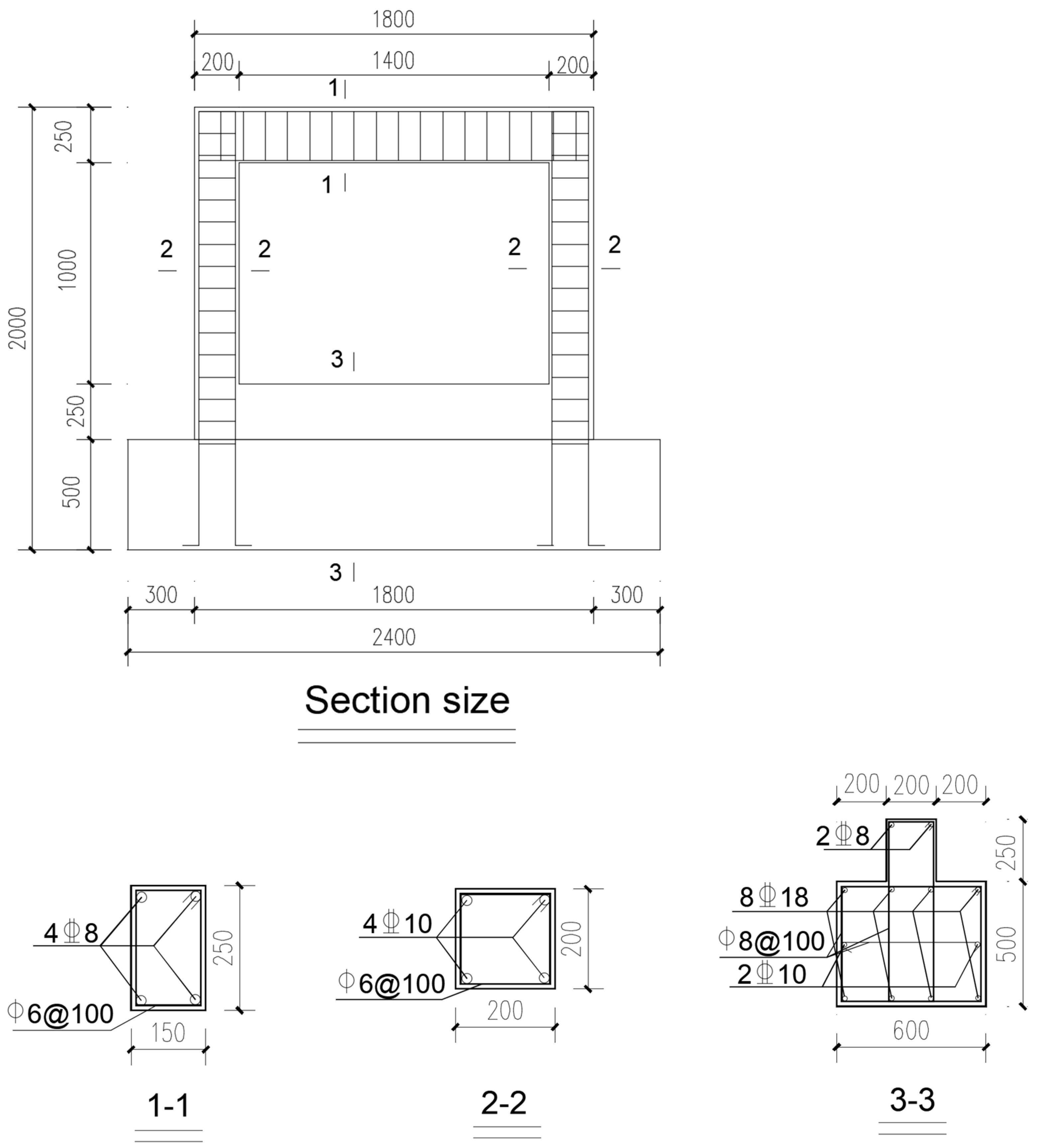
3.1. Concrete Frame Parameters

The structural prototype is a single frame positioned in the Y direction in the middle of the top floor of a five-story frame structure office building in Shenzhen. According to the similarity theory [22], the scale model is determined as the test component according to a 1:2 ratio, in which the floor height of the scale model is 1500 mm, the span is 2400 mm, the section dimensions of the existing frame column are 200 × 200 mm, the beam section dimensions are 150 × 250 mm, the concrete strength grade is C30, the longitudinal reinforcement model is HRB400, the stirrup model is HPB300, and the specific size and reinforcement are shown in Figure 3 and Table 1.

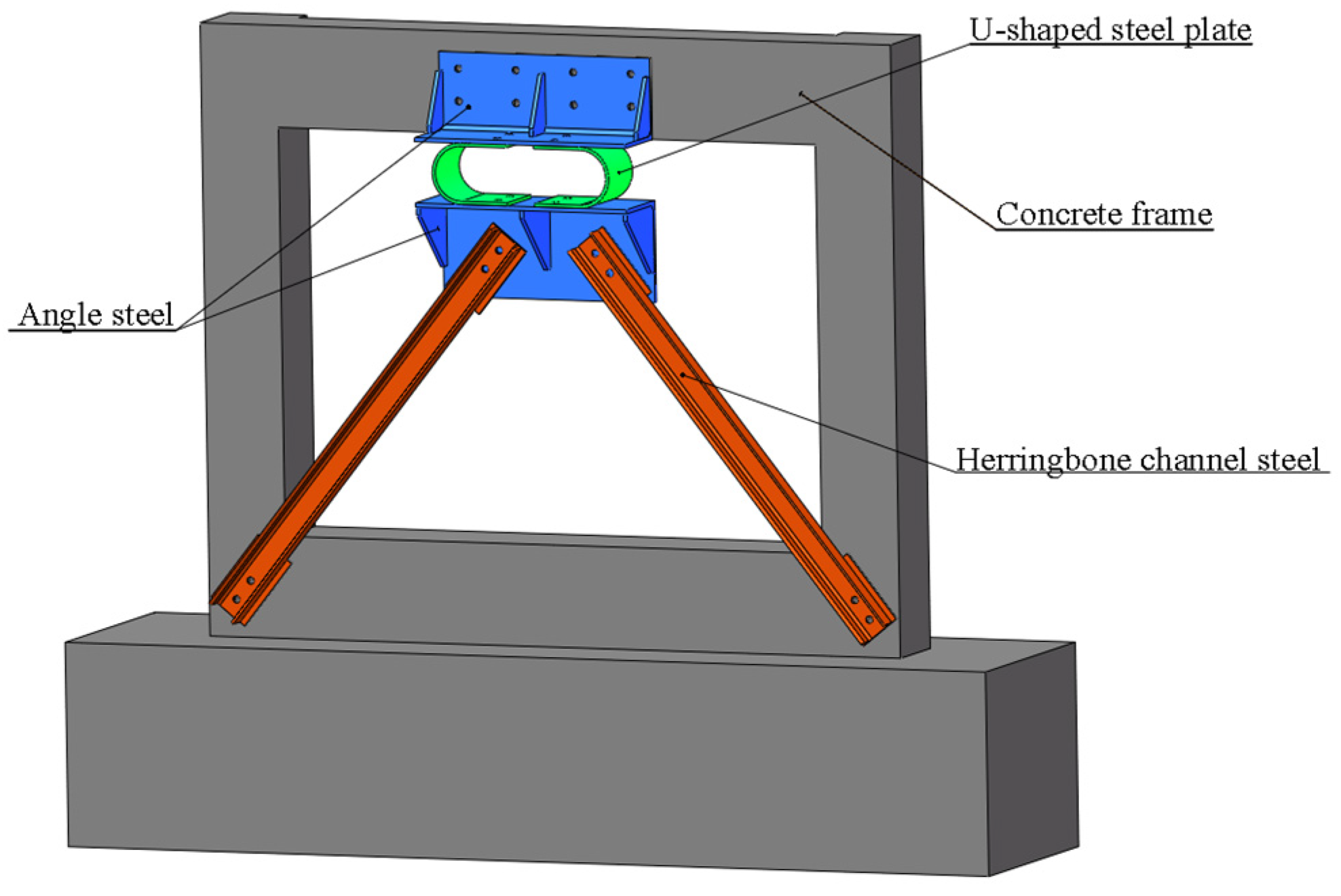
3.2. Design of Attached U-Shaped Steel Plate Sub-Structure

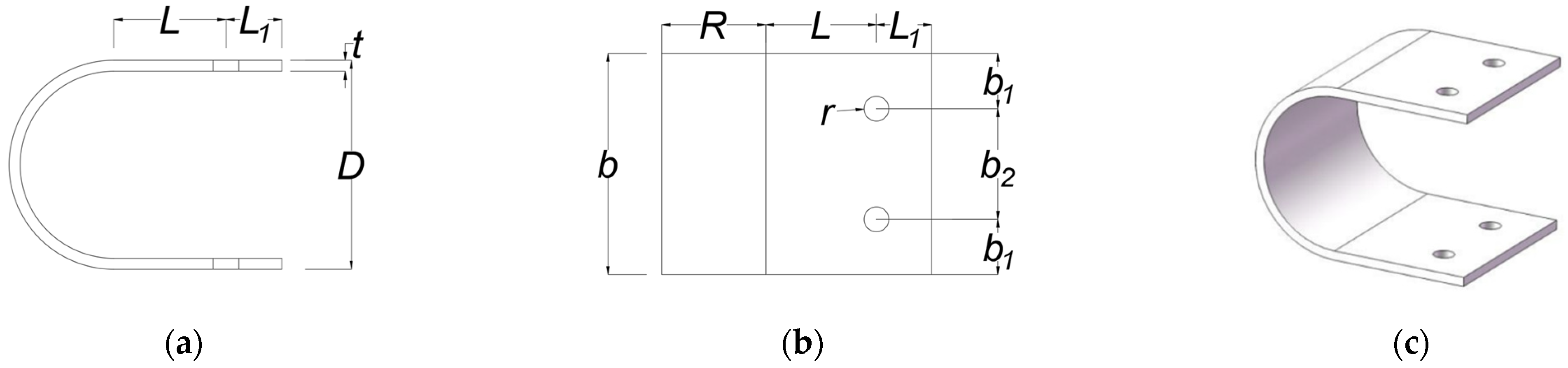
3.2.1. Design of the U-Shape Steel Plate

As shown in Figure 4, the invention relates to a method for strengthening a structure by externally attaching a U-shaped steel plate, which mainly dissipates earthquake energy through the bending–stretching deformation of the U-shaped steel plate and reduces the earthquake response of the whole frame structure. The yield load and stiffness of the U-shaped steel plate are important parameters for the design of the attached U-shaped steel plate sub-structure. Hongkai Du et al. [23] theoretically derived the mechanical properties of a U-shaped steel plate in the elastic stage, combined with multiple groups of test data; modified the theoretical derivation formula; and obtained the following empirical formula of yield load and initial stiffness of a U-shaped metal damper with a correction coefficient. The mechanical model proposed by Hongkai Du et al. [23] is directly cited in the research on the reinforcement method of the attached U-shaped steel plate structure. The mechanical model and form of the U-shaped steel plate are shown in Formulas (1) and (2) and Figure 4.
F = α σ b t 2 6 R
k = β E b t 3 6 π R 3
In Formulas (1) and (2): F represents the yield load of the U-shaped steel plate; k represents the initial stiffness of the U-shaped steel plate; t represents the thickness of the U-shaped steel plate; R represents the radius of the arc section of the U-shaped steel plate; E represents the elastic modulus of the U-shaped steel plate; and α and β represent the correction coefficients, which are 1.6 and 0.45, respectively. σ: fy = 235 N/mm2; E: 2.1 × 10⁴ Mpa.
In order to explore the function of this reinforcement method and the reinforcement effect of U-shaped steel plates of different specifications, three kinds of U-shaped steel plates with different specifications were designed with reference to the design method reported by Qu B et al. [12]. The specific specifications are shown in Table 2.

3.2.2. Connection of the U-Shaped Steel Plate

The U-shaped steel plate structure is a unified steel sub-structure composed of U-shaped steel plates, channel steel, and angle steel connected by high-strength bolts. No. 8 channel steel was uniformly used in this experiment. The yield bearing capacity of the U-shaped steel plate structure was determined according to Formula (1), and the end of the channel steel was designed according to the following bearing capacity relationship: the shear bearing capacity of the bolt bar ≥ the bearing capacity of the bolt hole wall ≥ the bearing capacity of the channel steel web [24]. For the convenience of installation, the weight of the angle steel was reduced as much as possible while meeting the design-specified strength and stiffness. The thickness ratio of the angle steel to the U-shaped steel plate was proposed to be 1.25. The length of the angle steel was determined according to the number of U-shaped steel plates. During testing, high-strength bolts were embedded before the frame was poured. Considering the weight of the steel sub-structure itself and the symmetry and stability of the installation openings, the U-shaped steel plate sub-structure and the frame were connected using 12 high-strength bolts. Within the U-shaped steel plate sub-structure, the U-shaped steel plate is connected to the angle steel by M16 high-strength bolts.
Three test specimens with U-shaped steel plate sub-structures were designed for the test, denoted as F1, F2, and F3, respectively, and the details of each test specimen are shown in Figure 5 and Table 3.

3.3. Test Loading and Measurement Scheme

3.3.1. Loading Device and Loading Rules

The WAW-J1200J active-follow-up-type comprehensive loading test system was used in the test. The unreinforced test specimen and three U-shaped steel plate test specimens with different specifications were subjected to low-cyclic loading controlled by displacement, and the loading system was formulated according to the Specifications for Seismic Test of Buildings [25]. Considering the size of the distribution beam and the safety of the test, no vertical load was applied to the test frame. The specific loading diagram is shown in Figure 6a. In the test, the displacement step increment was 1mm, and each displacement value was cycled once until the horizontal load of the frame dropped to 85% of its peak horizontal bearing capacity. The loading system is shown in Figure 6b.

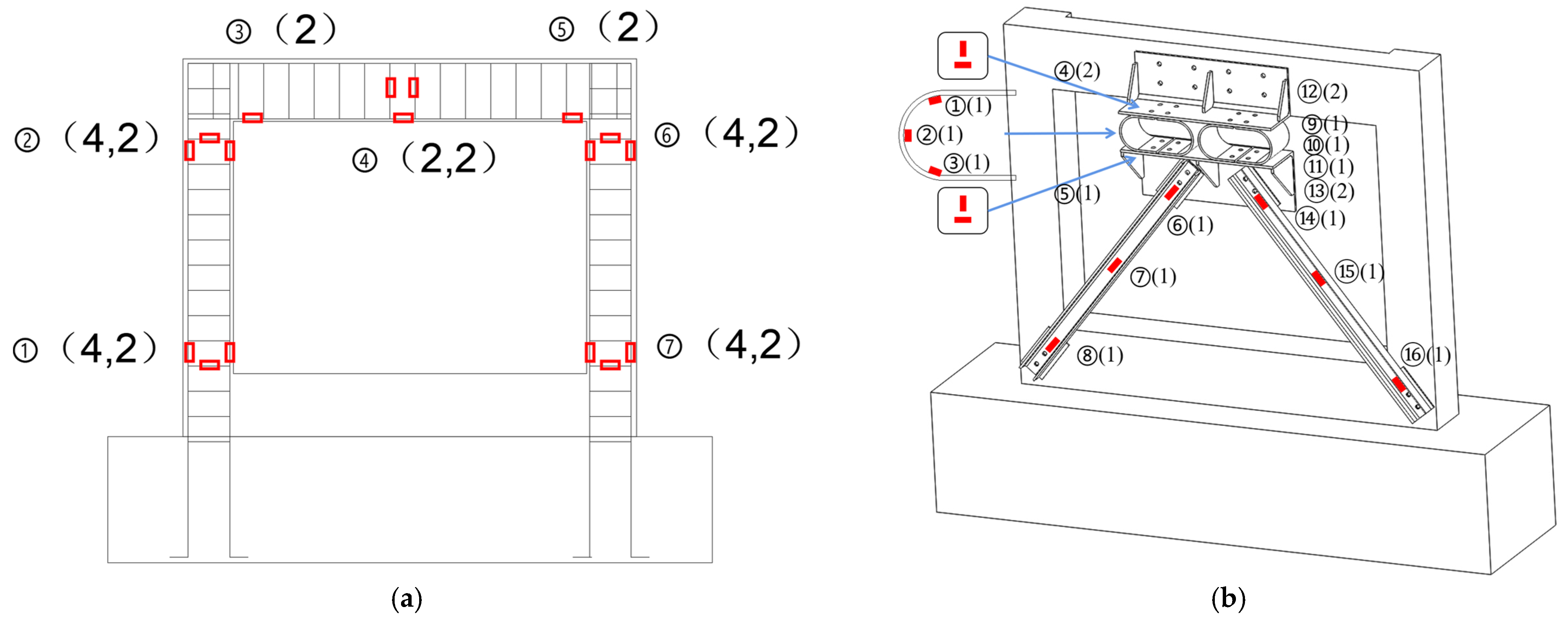
3.3.2. Measurement Scheme

The horizontal displacement of the frame was measured and documented using the built-in displacement sensor of the loading test system, and the accuracy of the data was verified by installing the displacement sensor at the end of the frame beam. The horizontal force acting on the frame was measured and recorded by the force sensor built into the loading test system. Strain gauges were arranged at the ends of the frame beams and columns, as well as within the internal rebar, the circular arc sections of the U-shaped steel plates, the angle steel, and the channel steel, and the strain of each component was measured and recorded using a static strain data collector. The specific strain gauge arrangement is shown in Figure 7.

4. Analysis of Pseudo-Static Test Phenomena and Results

According to the proposed test plan, in this phase of the study, we conducted pseudo-static tests under horizontal low-cycle load on four frame test specimens, observed and recorded the test phenomena of the frames and steel sub-structures, recorded and output the hysteresis curve and corresponding strain data of the frames, and analyzed the overall seismic performance and deformation energy dissipation capacity of the frames.

4.1. Test Phenomena

For unreinforced test specimen F0, when the displacement load was 4 mm, tiny cracks emerged at the base of the column, and the horizontal load was 17.1 kN. When the displacement load was 10 mm, the horizontal bearing capacity rose slowly. At this time, the horizontal load was 36 kN, and it was judged that the reinforcement in the frame model entered the yield stage. When the displacement reached 22 mm, the horizontal load tended to be stable, and the crack developed into a through crack. At this time, the horizontal load was 44 kN, which is close to the peak load. When the displacement load was 32 mm, the crack width at the end of the column was about 2 mm, the horizontal load dropped to less than 85% of the ultimate bearing capacity, the concrete at the end of the column became obviously damaged, and concrete spalling occurred.
For the three reinforced test specimens, the failure phenomena were basically the same; there were no obvious diagonal cracks in the middle of the frame beam, that is, there was no shear failure in the middle of the frame beam; the failure mode of the whole frame was clear; and the ultimate bearing capacity was significantly improved compared with that of F0. The overall substructure was stable, properly connected to the concrete, and able to coordinate deformation. Taking F1 as an example, the failure process and form of the strengthened specimen are introduced in this section. When the displacement load was 3 mm, the first crack appeared due to the loading effect of the horizontal actuating head, and the horizontal load at this time was 32.6 kN. When the displacement load was 9 mm, transverse cracks appeared outside the A-column of the frame, the width of the cracks was about 0.3 mm, and the horizontal load was 56.8 kN. When the displacement load was 18 mm, the concrete in the middle and lower parts of the frame beam was compressed and broken due to eccentricity, and the horizontal load was 62 kN, which is close to the peak load of the frame. After continuing to record until 32 mm, a large number of compression cracks appeared on the side away from the sub-structure, at which time the horizontal load had dropped to below 85% of the ultimate bearing capacity, and the test specimen had been damaged.

4.2. Analysis of Frame Test Results

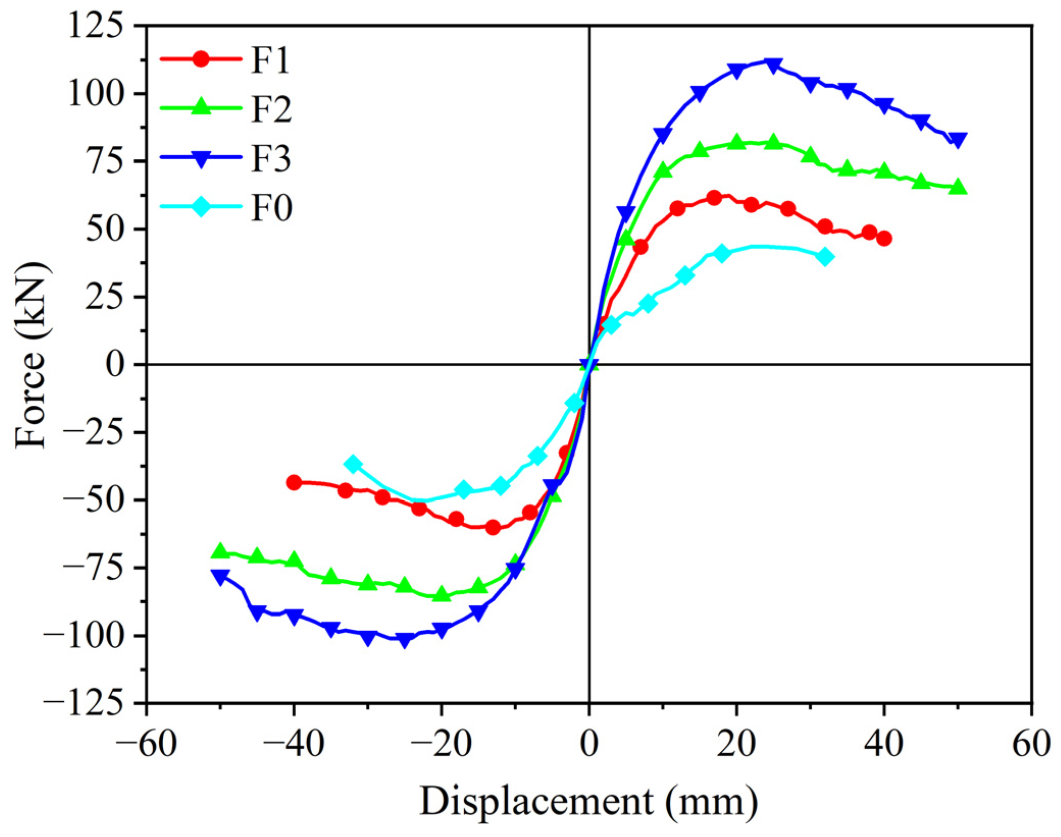
4.2.1. Comparative Analysis of Hysteresis Curve and Skeleton Curve

The hysteresis curve is the main basis for evaluating the seismic performance of structural components in seismic analysis. It can be effectively used to determine the stiffness degradation and energy consumption of a structure during the process of stress. The hysteresis curves of test specimens F0, F1, F2, and F3 are shown in Figure 8.
It can be seen from the figure that, compared with the unreinforced test specimen F0, the final bearing capacity of test specimens F1, F2, and F3 was significantly improved, and the yield point was more backward. The reinforcement method of installing an externally attached U-shaped steel plate sub-structure enhanced the yield displacement of the entire structural frame. Although the peak load, peak displacement, and ultimate displacement of test specimens F1, F2, and F3 are different due to the different specifications of the U-shaped steel plates, the shapes of the hysteresis loops are basically similar, and the hysteresis curves are full, which shows that the U-shaped steel plates had ideal deformation and energy dissipation capacity throughout the whole loading process of the frame. After reaching the peak load, F1, F2, and F3 exhibited obvious flat sections. From the analysis of the loading displacement degree, it can be gleaned that the U-shaped steel plate can provide greater resistance at this stage (that is, the U-shaped steel plate can still dissipate energy and store energy to a certain extent in the later stage of the test), and the seismic and shock absorption effects of the composite deformation shape are more ideal.
The skeleton curve is used as an important basis for determining the characteristic points in the restoring force model. The stiffness characteristics and the deformation capacity of the whole structure can be analyzed using and judged according to the trend and the approximate shape of the skeleton curve. The horizontal peak points of the hysteresis curve under the same direction of control displacement loading at all levels are connected in sequence, and the obtained curve is the skeleton curve of the test specimen. The skeleton curves of test specimens F0, F1, F2, and F3 are shown in Figure 8. The additional lateral resistance force of the U-shaped steel sheets, that is, the yield load, was determined using Formula (1); the difference ratios of test specimens F1, F2, and F3 are all within ±10%, the test values are close to the theoretical values, and the bearing capacity of the U-shaped steel plate satisfies the superposition relationship. Combined with the skeleton curve in Figure 9 and the bearing capacity comparison in Table 4, the peak load of F1, F2, and F3 increased with the improvement of the specifications of the U-shaped steel plates, and the peak bearing capacity of each test specimen was 1.31, 1.79, and 2.28 times that of F0, indicating that the seismic capacity of the original RC frame was significantly improved by the attached U-shaped steel plate sub-structure reinforcement. At the same time, the bearing capacity of reinforced frame models F1, F2, and F3 decreased slowly, which indicates that the failure mode of the reinforcement method is still plastic failure, and it still has good energy dissipation properties under large displacement deformation.

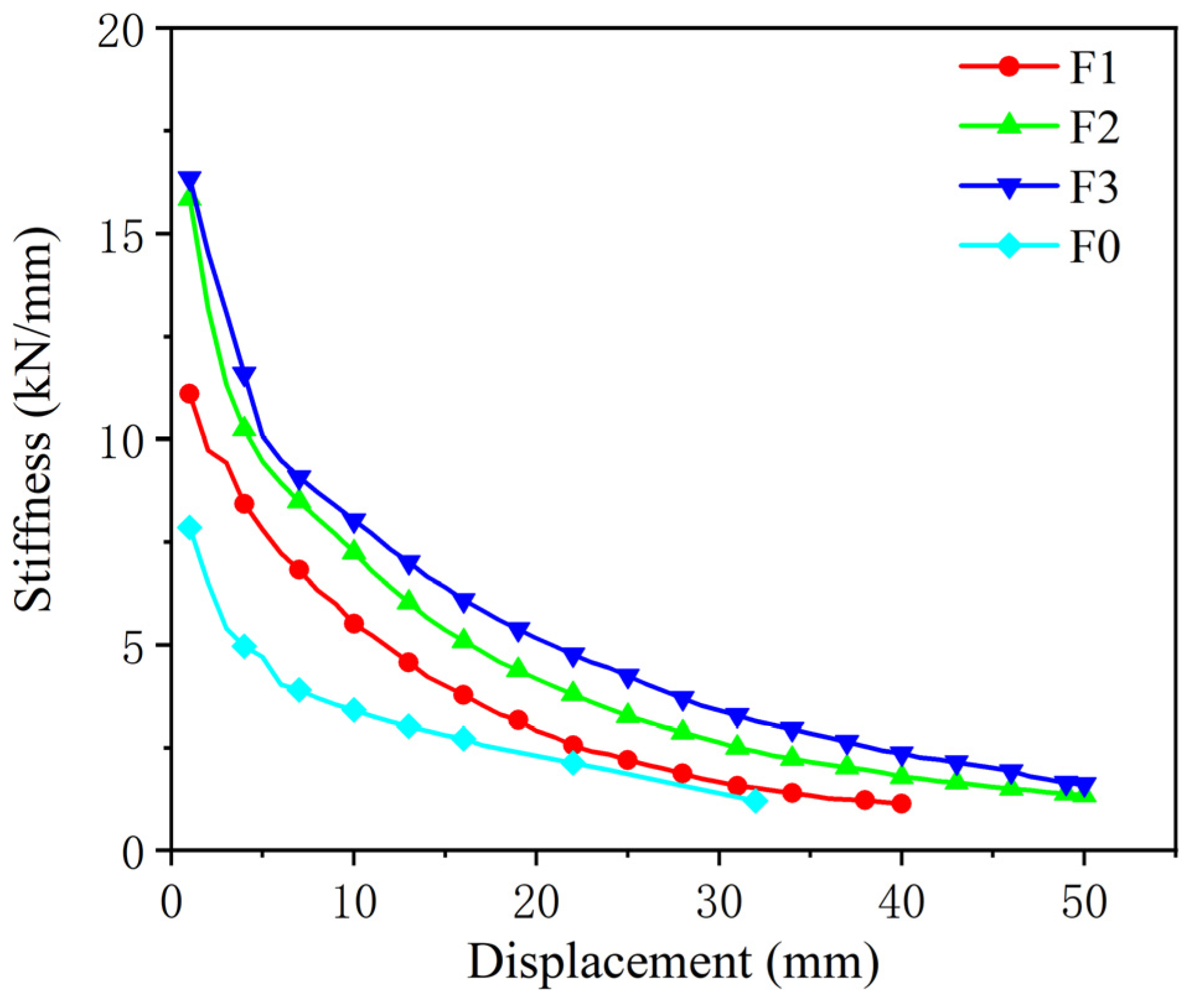
4.2.2. Analysis of Stiffness Degradation

The lateral stiffness of the RC frame decreased gradually with the increase in the loading displacement and the crack development of the frame. The stiffness degradation is represented by the secant stiffness K of the frame model. The change rule of the K value can reflect the change process of the seismic performance of the frame model. The calculation formula is as follows [26]:
K = F + + F + +
The formula:  F + F : The positive and negative peak loads under the same displacement cyclic load; + ,   : The positive and negative maximum displacements of the vertex under the same displacement cyclic load.
The stiffness degradation curves of each frame model are shown in Figure 10. Table 5 shows the calculated values and a comparison of the stiffness of each frame model and sub-structure. The initial stiffness of the U-shaped steel plate was determined using Formula (2). It can be seen from the table that the difference ratio of F1 to F3 in the test specimen is within 15%, that the test value is close to the theoretical value, and that the deviation of F2 is slightly higher, indicating that the bearing capacity of the U-shaped steel plate satisfies the superposition relationship. The stiffness degradation curves of F1, F2, and F3 in the test specimen decreased gently, indicating that the bending and tension of the U-shaped steel plates met the design requirements and could provide additional stiffness steadily and continuously during the whole loading process.

4.2.3. Ductility Factor

The ductility factor can effectively reflect the plastic deformation capacity of structural components, which indicates their seismic performance [27]. The larger the ductility factor, the better the overall ductility of the specimen, and the stronger the energy dissipation capacity, which is defined as the ratio μ of the ultimate deformation u of the specimen to its yield displacement y , as shown in Formula (4).
μ = u y
It can be seen from Table 6 that the overall ductility of frame models F1, F2, and F3 is good, and the ratio of the ductility coefficient to that of the control specimen, F0, is more than 1.28, which indicates that the reinforcement of the existing structure with the attached U-shaped steel plate sub-structure can improve the overall ductility of the frame and enhanced its deformation capacity. Additionally, the U-shaped steel plate can deform stably even after the frame reaches its peak load, providing resistance. As a result, this improves the limit displacement and overall ductility of the frame.

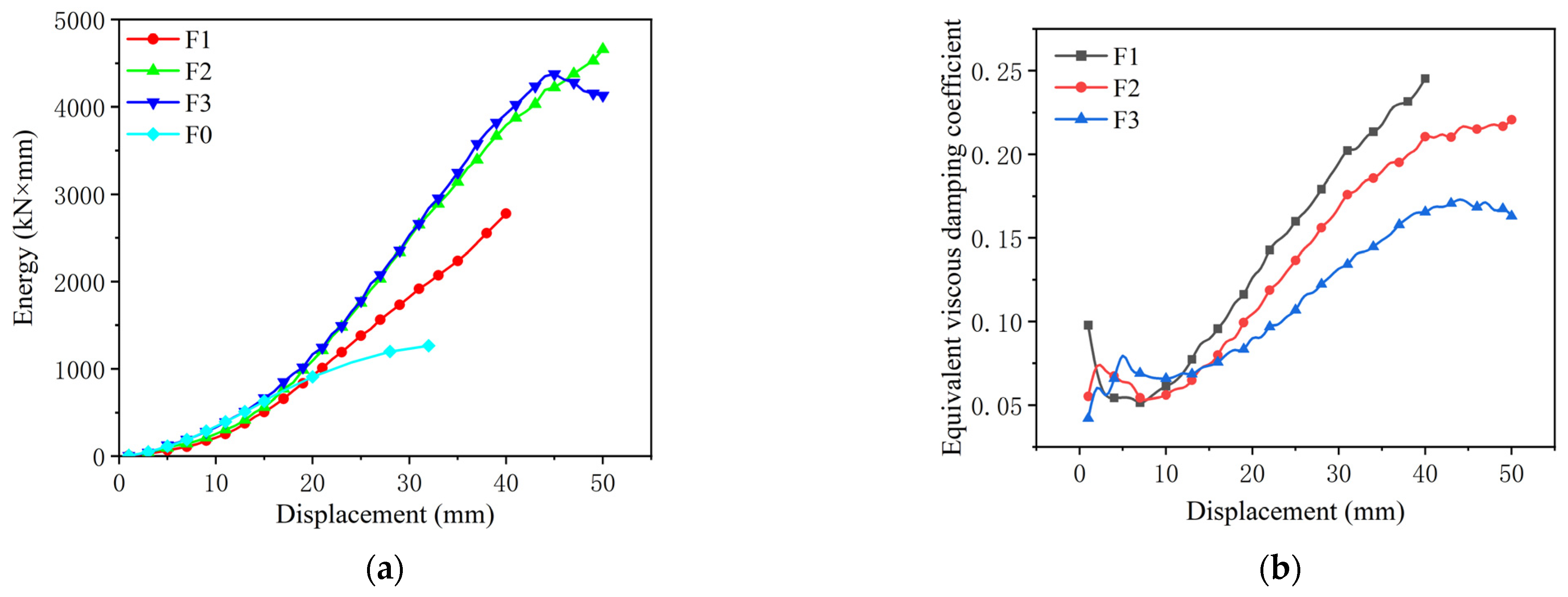
4.2.4. Analysis of Energy Dissipation

The energy dissipation capacity of the structure can be reflected by the hysteresis curve. The cumulative energy dissipation is measured according to the area enclosed by the load–displacement hysteresis curve of a specimen [26]. The larger the area of the hysteretic loop, the better the energy dissipation capacity of the specimen. Figure 11a shows the energy dissipation curves of test specimens F0, F1, F2, and F3. It can be seen from the figure that when each frame model is in the elastic stage, the loading and unloading paths in the early stage of the hysteresis curve are quite close, and each frame model is in the elastic stage, with low energy consumption, and no obvious differences can be seen. With the increase in displacement, the energy consumption of test specimens F1, F2, and F3 was significantly greater than that of the unreinforced test specimen F0, which indicates that the energy consumption capacity of the RC frame structure can be effectively improved via the reinforcement of the U-shaped steel plate sub-structure. For test specimens F1, F2, and F3, the U-shaped steel sub-structure was used for reinforcement, continuing to provide stable resistance to the existing frame, and the ultimate displacement of the frame was significantly increased, so its energy consumption curve could continue to increase in a stable increment. When the load applied to F3, with higher resistance, reached the ultimate displacement, the energy dissipation capacity decreased, while that of F2 continued to increase, which is due to the increase in concrete cracking in F2, resulting in a decline in its energy dissipation capacity in the later stage, indicating that energy dissipation capacity is related to the overall resistance and cracking of the frame. From the beginning of loading to the failure of the frame, the order of the total energy consumption of the frame is F2, F3, F1, and F0 from high to low.
In addition to cumulative energy dissipation, the equivalent viscous damping coefficient ξ e is also an important index for determining the energy dissipation capacity of a structure [28]. The equivalent viscous damping coefficient is the ratio of the envelope area of the hysteresis curve to the corresponding elastic potential energy, reflecting the full degree of the hysteresis curve and serving as a judgment index of energy dissipation efficiency. Its calculation formula is shown in Figure 12 and Formula (5), and the equivalent viscous damping coefficients of each test specimen are shown in Figure 11b.
ζ e = 1 2 π S A B C D S O B F + S O D E
Cumulative energy consumption is the total energy consumption of a research object, and the equivalent viscous damping coefficient is the energy consumption efficiency of the research object. The two concepts are different. The equivalent viscous damping coefficient of a structure with more cumulative energy dissipation is not necessarily large. On the contrary, the cumulative energy dissipation of a structure with a larger equivalent viscous damping coefficient is also not necessarily large. As shown in Figure 11, the total energy consumption of the frame from high to low corresponds to the order of F2, F3, and F1, while the equivalent viscous damping coefficient decreases with the increase in the thickness and number of U-shaped steel plates. Considering the cumulative energy consumption and energy consumption efficiency, test specimen F2 has better energy dissipation performance.

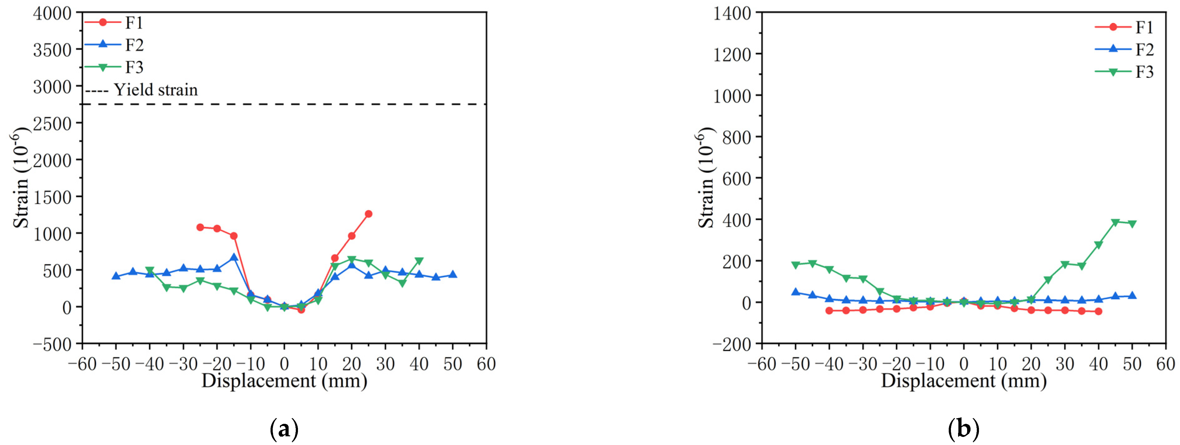
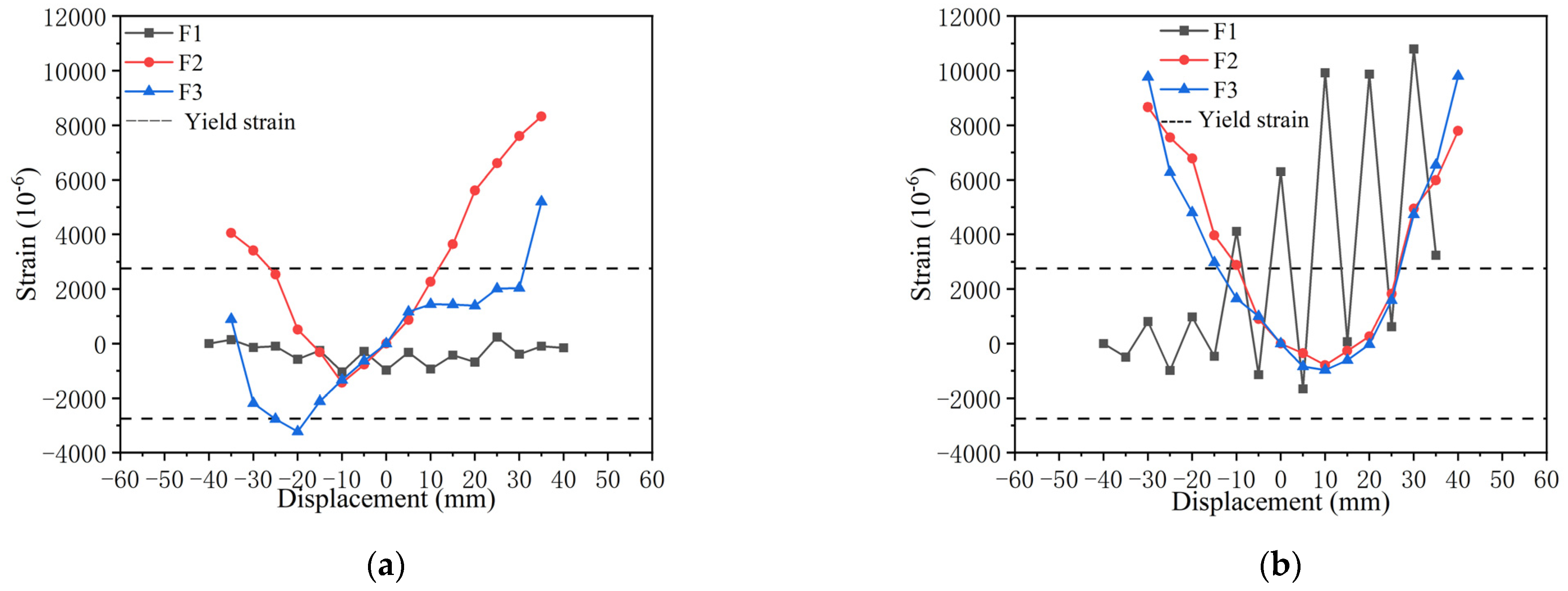
4.2.5. Analysis of Strain

Due to the symmetry of the frame, only strain data on one side are presented. The strain of longitudinal bars in the middle of the beam span is shown in Figure 13a. It can be seen from the figure that the longitudinal bar strains of F1, F2, and F3 are basically symmetric and positive. When the displacement load was ±20 mm, the strain of F2 and F3 tended to be gentle and the amplitude decreased slightly. Meanwhile, it can be seen from Figure 13b that the stirrup strain values of F1, F2, and F3 are stable, and the stirrup strain of F3 increases with the increase in displacement. The reinforcement strain of the frame beam is basically consistent with the experimental phenomenon, and the overall failure mode of the frame is reasonable.
Figure 13 shows the strain in the middle and the edge of the left U-bar. As shown in Figure 14a, the strain in the middle of the U-shaped steel plate of F1 changes smoothly, F2 basically shows positive strain with loading, and F3 shows positive strain with positive loading and negative strain with reverse loading. In the three test specimens, the middle part of the U-shaped steel plate yielded. As shown in Figure 14b, the strain at the edge of the U-shaped steel plate of F1 fluctuated greatly, and F2 and F3 developed symmetrically with the same trend, basically showing positive strain. In the three test specimens, the edges of the U-shaped steel sheets all yielded. Based on the strain of the U-shaped steel plate in Figure 13 and the test phenomenon, it can be seen that the U-shaped steel plate can effectively induce ideal deformation and energy consumption, which verifies the reinforcement effectiveness of the steel sub-structure. At the same time, the consistent strain trend of F2 and F3 shows that the mechanical characteristics of the U-shaped steel plates are clear and predictable, and this can provide effective guidance for the number of U-shaped steel plates to employ and their arrangement in sub-structure reinforcement.

5. Conclusions and Prospects

This paper proposes a seismic retrofit method for an externally attached U-shaped steel plate sub-structure, which follows the concept of ‘reinforcing while using’ and is composed of U-shaped steel plates and herringbone channel steel, allowing it to satisfy the needs of multiple retrofits. Four frames were designed and manufactured, and a horizontal cyclic load was applied in the pseudo-static test. According to the experimental phenomena observed over the course of the whole test process, including the development of cracks, the stress deformation and failure modes of the substructures, the hysteresis curves, and the strain data obtained from the tests, the results of the unreinforced test specimen and the three U-shaped-steel-plate-reinforced test specimens with different specifications were compared and analyzed, and the seismic indices such as stiffness, ductility, and energy consumption were compared and analyzed.
According to the analysis results, the following conclusions were drawn:
(1)
The test values of bearing capacity and lateral stiffness of test specimens F1, F2, and F3 are close to the theoretical predicted values, showing that the mechanical model of U-shaped steel plates can be effectively applied to the overall design of U-shaped steel plate sub-structures. The bearing capacity of the U-shaped steel plate presents an ideal superposition phenomenon, which makes the design idea clearer and more reliable.
(2)
The horizontal carrying capacity of test specimens F1, F2, and F3 strengthened by the external U-shaped steel plate sub-structures was greatly improved, and their maximum horizontal force was 1.43, 1.89, and 2.57 times of that of the unreinforced specimen F0. The initial lateral stiffness of the frame also increased significantly, being 1.41, 2.02, and 2.08 times that of the unreinforced specimen, and the stiffness degradation rate also decreased significantly. The higher the resistance level of the substructure, the lower the stiffness degradation rate.
(3)
Comparing the unreinforced test specimen and the reinforced test specimen, the externally attached U-shaped steel plate sub-structure reinforcement has ideal damping and reinforcement ability, which can effectively improve the seismic performance of the existing structure. The failure mode of the original structure did not change in test specimens F1, F2, and F3, and no obvious shear cracks appeared in the frame beam. The deformation of the substructure was concentrated in the U-shaped steel plate, and the sub-structure was stable overall. The failure mode consisted of concrete damage and a plastic hinge appearing at the lower end of the frame column. Failure patterns are also reflected in ductility. The ductility of test specimens F1, F2, and F3 was 1.28 times higher than that of F0, the unreinforced specimen. Due to the stable bending and stretching deformation of the U-shaped steel plates, the overall frame ductility and structural limit displacement were improved, and the hysteresis curves of test specimens F1, F2, and F3 were fuller and had higher energy dissipation capacity. The order of total energy consumption of the frame was F2, F3, and F1, ordered from highest to lowest, and the equivalent viscous damping coefficient decreased with the increase in the thickness and number of U-shaped steel plates. Concerning cumulative energy consumption and energy consumption efficiency, experimental specimen F2 has better energy dissipation performance.
(4)
The results of the strain analysis of the steel bars were consistent with the failure mode response of the four specimens of test frames: the U-shaped steel plates in test specimens F1, F2, and F3 yielded, while the other steel members did not show yielding, indicating that the U-shaped steel plate sub-structure design is reasonable and stable overall and that U-shaped steel plates can continue to deform and play a role and, at the same time, provide effective guidance for the enumeration and layout design of U-shaped steel plates.
(5)
The externally attached U-shaped steel plate sub-structure was connected to the existing frame through bolts, and the force transmission was clear, forming a lateral force resistance system. The mode of bolt connection reduces the number of wet operations, provides convenience for reinforcement construction, and meets the requirements of multiple reinforcement of in-service concrete structures throughout their life cycles.
(6)
At present, there is still insufficient research on the strengthening method applied to externally U-shaped steel plate sub-structures. The mechanical model of a U-shaped steel plate can be further studied to analyze the change in stiffness during the transition from flexural–tensile deformation to tensile deformation under the condition of large displacement and deepen the current two-fold mechanical model to a three-fold mechanical model. The damping potential of the reinforced U-shaped steel plate sub-structure under rare earthquakes in high-intensity areas was further studied.
(7)
In this study, we applied pseudo-static tests to scaled models, wherein the conditions are different from the actual situation to some extent. Subsequently, test studies on the reinforcement of external steel substructures of multi-story and multi-span full-scale reinforced concrete frames can be carried out, including pseudo-static tests and shaking table tests, so as to investigate the seismic performance of these two construction methods more comprehensively. The influence of the external steel substructure on the mechanical properties of the main frame has been summarized, and the popularization and application of this substructure in the seismic reinforcement of reinforced concrete frame structures are promoted.

Author Contributions

Methodology, Y.L.; formal analysis, X.W.; investigation, Z.L.; writing—original draft, Z.X.; writing—review and editing, W.W.; supervision, Z.L. and W.W. All authors have read and agreed to the published version of the manuscript.

Funding

The research was funded by Shenzhen Science and Technology Research and Development Foundation, grant number 20200812110216001.

Data Availability Statement

The data used to support the findings of this study are included within the article.

Conflicts of Interest

The authors declare no conflict of interest.

Nomenclature

F The yield load of the U-shaped steel plate.
k The initial stiffness of the U-shaped steel plate.
t The thickness of the U-shaped steel plate.
R The radius of the arc section of the U-shaped steel plate.
E The elastic modulus of the U-shaped steel plate.
α ,   β The correction coefficients, which are 1.6 and 0.45, respectively.
F + ,   F The positive and negative peak loads under the same displacement cyclic load
+ ,   The positive and negative maximum displacements of the vertex under the same displacement cyclic load
μ Ductility factor
u The ultimate deformation of the specimen
y The yield displacement of the specimen
ζ e Equivalent viscous damping coefficient

References

  1. Wang, J. Optimization Design and Reliability Analysis for Reinforced Concrete Frame Structural Member. Master’s Thesis, Xi‘an University of Architecture and Technology, Xi‘an, China, 2016. [Google Scholar]
  2. Quan, S. Study on Seismic Behavior of Reinforced Concrete Beams and Columns. Master’s Thesis, Tianjin University, Tianjin, China, 2017. [Google Scholar]
  3. Zhang, M. Research on Reliability and Residual Life of Reinforced Concrete Beam Strengthened by Steel Plate. Master’s Thesis, Tianjin University, Tianjin, China, 2017. [Google Scholar]
  4. Xun, L.; Shi, W.; Jin, W. Summary and comparison of traditional and innovative seismic strengthening technologies. Struct. Eng. 2012, 28, 101–105. [Google Scholar] [CrossRef]
  5. Qu, Z.; Zhang, L. State of the art and development tendency of seismic retrofit for reinforced concrete structures in Japan. Earthq. Eng. Eng. Dyn. 2013, 33, 61–74. [Google Scholar]
  6. Ji, X. Graphic Seismic Strengthening Technology of Reinforced Concrete Structure; China Architecture & Building Press: Beijing, China, 2010. [Google Scholar]
  7. Cao, X.-Y.; Feng, D.-C.; Wu, G. Seismic Performance Upgrade of RC Frame Buildings Using Precast Bolt-Connected Steel-Plate Reinforced Concrete Frame-Braces. Eng. Struct. 2019, 195, 382–399. [Google Scholar] [CrossRef]
  8. Yin, B.; Cheng, S.; Ji, F.; Yuan, D.; Lei, C.; Hong, X. Experimental study on seismic performance of frame structure strengthened with attached steel braces. Earthq. Resist. Eng. Retrofit. 2019, 41, 109–113. [Google Scholar] [CrossRef]
  9. Yongxuan, Z. Research on Seismic Reinforcement Technology of Existing RC Frame Structure Reinforced by Additional Diagonal Bracing. Master’s Thesis, Beijing University of Civil Engineering and Architecture, Beijing, China, 2023. [Google Scholar]
  10. Yulin, F. Study on Seismic Behaviors of Existing Reinforced Concrete Frame Strengthened with Self-Centering Members. Master’s Thesis, Beijing University of Civil Engineering and Architecture, Beijing, China, 2023. [Google Scholar]
  11. Jinsheng, S.; Liwei, L.; Shaozhuo, J.; Ningning, P. Experimental study on seismic performance of external energy dissipative swing steel frame structure. Build. Struct. 2022, 52, 92–97. [Google Scholar] [CrossRef]
  12. Fantao, M.; Xingqun, R.; Jianfeng, Z. Seismic performance of existing RC frame structure retrofitted with external energy dissipation substructure. Earthq. Resist. Eng. Retrofit. 2023, 45, 156–163. [Google Scholar] [CrossRef]
  13. Qu, B.; Dai, C.; Qiu, J.; Hou, H.; Qiu, C. Testing of Seismic Dampers with Replaceable U-Shaped Steel Plates. Eng. Struct. 2019, 179, 625–639. [Google Scholar] [CrossRef]
  14. Zhai, Z.; Guo, W.; Yu, Z.; He, C.; Zeng, Z. Experimental and Numerical Study of S-Shaped Steel Plate Damper for Seismic Resilient Application. Eng. Struct. 2020, 221, 111006. [Google Scholar] [CrossRef]
  15. Wang, H. Study on Seismic Performance and Fragility Analysis of Existing Concrete Frames Upgraded by Metallic Dampers. Master’s Thesis, Hefei University of Technology, Hefei, China, 2023. [Google Scholar]
  16. Guo, L.; Wang, J.; Wang, W.; Wang, H. Performance-based seismic design and vulnerability assessment of concrete frame retrofitted by metallic dampers. Structures 2023, 57, 105073. [Google Scholar] [CrossRef]
  17. Lee, C.-H.; Ryu, J.; Oh, J.; Yoo, C.-H.; Ju, Y.K. Friction between a New Low-Steel Composite Material and Milled Steel for SAFE Dampers. Eng. Struct. 2016, 122, 279–295. [Google Scholar] [CrossRef]
  18. Lee, C.-H.; Ryu, J.; Kim, D.-H.; Ju, Y.K. Improving Seismic Performance of Non-Ductile Reinforced Concrete Frames through the Combined Behavior of Friction and Metallic Dampers. Eng. Struct. 2018, 172, 304–320. [Google Scholar] [CrossRef]
  19. Hu, B.; Lv, H.; Kundu, T. Experimental study on seismic behavior of reinforced concrete frame in primary and middle schools with different strengthening methods. Constr. Build. Mater. 2019, 217, 473–486. [Google Scholar] [CrossRef]
  20. TahamouliRoudsari, M.; Entezari, A.; Hadidi, M.; Gandomian, O. Experimental Assessment of Retrofitted RC Frames with Different Steel Braces. Structures 2017, 11, 206–217. [Google Scholar] [CrossRef]
  21. TahamouliRoudsari, M.; Eslamimanesh, M.B.; Entezari, A.R.; Noori, O.; Torkaman, M. Experimental Assessment of Retrofitting RC Moment Resisting Frames with ADAS and TADAS Yielding Dampers. Structures 2018, 14, 75–87. [Google Scholar] [CrossRef]
  22. GB50011-2010; Code for Seismic Design of Buildings. China Architecture & Building Press: Beijing, China, 2010.
  23. Du, H.; Han, M.; Yan, W. Study on the calculation method of mechanical characteristics for constrained U-shaped steel plates. China Civ. Eng. J. 2014, 47, 158–163. [Google Scholar]
  24. GB 50017-2017; Code for Design of Steel Structures. China Architecture & Building Press: Beijing, China, 2016.
  25. JGJ/T 101-2015; Specification for Seismic Test of Buildings. China Architecture & Building Press: Beijing, China, 2015.
  26. Xiong, Z.; Wang, S. Structural Experiment of Civil Engineering; China Architecture & Building Press: Beijing, China, 2014. [Google Scholar]
  27. Luzhong, G.; Xiangyu, G.; Jianwei, X.; Chuheng, H.U.; Na, W.U. Experimental research on seismic performance of BRB concrete frames. J. Build. Struct. 2011, 32, 101–111. [Google Scholar] [CrossRef]
  28. Dan, Z.; Yuwen, X. Mechanical Properties and Parameter Analysis of U-shaped Metal Dampers. Pop. Stand. 2022, 372, 148–149. [Google Scholar]
Figure 1. Schematic diagram of the reinforcement method for externally attached U-shaped steel plate sub-structures.
Buildings 13 03058 g001
Figure 2. Research route and framework.
Buildings 13 03058 g002
Figure 3. Structural dimensions and reinforcement details (unit: mm).
Buildings 13 03058 g003
Figure 4. U-shape steel plate: (a) front view, (b) vertical view, and (c) 3-D view.
Buildings 13 03058 g004
Figure 5. (a) Test specimen F1; (b) test specimens F2 and F3.
Buildings 13 03058 g005
Figure 6. (a) Loading diagram; (b) horizontal loading system.
Buildings 13 03058 g006
Figure 7. Arrangement of strain gauge. (a) Arrangement of strain gauge of reinforcement. (b) Arrangement of strain gauge of steel substructure.
Buildings 13 03058 g007
Figure 8. Hysteresis curves of test specimens. (a) Test specimen F0, (b) test specimen F1, (c) test specimen F2, and (d) test specimen F3.
Buildings 13 03058 g008
Figure 9. Skeleton curve of test specimen.
Buildings 13 03058 g009
Figure 10. Stiffness degradation curve.
Buildings 13 03058 g010
Figure 11. (a) Energy consumption curve; (b) equivalent viscous damping coefficient.
Buildings 13 03058 g011
Figure 12. Calculation of ζ e .
Buildings 13 03058 g012
Figure 13. Rebar strain. (a) Beam midspan longitudinal bars. (b) Beam midspan stirrups.
Buildings 13 03058 g013
Figure 14. U-shape steel plate strain. (a) Middle part of left U-shape steel plate. (b) Left U-shape steel plate edge.
Buildings 13 03058 g014
Table 1. Reinforcement list.
ComponentSection Size/mmlongitudinal Bar (HRB400)Stirrup (HRB300)
The original model frame column400 × 4002C20; 2C20A8@100
The original model frame beam300 × 5002C16; 2C16A8@100
The scale model frame column200 × 2002C10; 2C10A6@100
The scale model frame beam150 × 2502C8; 2C8A6@100
Table 2. Specifications of U-shaped steel plate (unit: mm).
Specificationt/mmb/mmD/mmL/mmL1/mmr/mmb1/mmb2/mm
181601508040164080
281601505030164080
3101601505030164080
Table 3. Specifications and parameters of test specimens.
NumberQuantity of U-Shaped Steel PlatesSpecifications of U-Shaped Steel Plates/mmUpper-Angle Steel/mmLower-Angle Steel/mmChannel SteelYield Force/kN
F128200 × 180 × 10 × 550250 × 190 × 10 × 550No. 817.1
F248200 × 180 × 10 × 550250 × 190 × 10 × 600No. 834.2
F3410200 × 180 × 10 × 550250 × 192 × 12 × 660No. 853.5
Table 4. Comparison of bearing capacities.
NumberOriginal Lateral Force/kNAdditional lateral Force/kNTheoretical Lateral Force/kNPositive Peak Value/kNNegative Peak Value/kNPeak Mean Value/kNDifference RatioPositive F(X)/F0Negative F(X)/F0
F0---43.5−50.046.75-1.001.00
F15017.167.162.3−60.061.16−8.85%1.431.20
F25034.284.282.0−85.483.70−0.59%1.891.71
F35053.5103.5111.9−101106.452.85%2.572.02
Note: Original lateral resistance: lateral resistance of original concrete; additional lateral force resistance: lateral force resistance of U-shaped steel sheet or channel steel; theoretical lateral force: the sum of original lateral force and additional lateral force; peak mean: mean of the sum of the absolute values of the positive peak and the negative peak; difference ratio: (peak mean value-theoretical lateral resistance)/theoretical lateral resistance.
Table 5. Comparison of stiffnesses.
NumberOriginal Stiffness (kN/mm)Additional Stiffness (kN/mm)Theoretical Initial Stiffness (kN/mm)Initial Stiffness (kN/mm)Difference RatioF(x)/F0
F07.85--7.85-1.00
F17.851.959.8011.1013.27%1.41
F27.853.9011.7515.8534.89%2.02
F37.857.6015.4516.355.83%2.08
Note: Original stiffness: lateral stiffness of original concrete; additional stiffness: lateral stiffness of U-shaped steel sheet or channel steel; theoretical initial stiffness: the sum of original stiffness and additional stiffness; difference ratio: (initial stiffness-theoretical initial stiffness)/theoretical initial stiffness.
Table 6. Ductility factor.
NumberF0F1F2F3
Ultimate displacement/mm32314441
Yield displacement/mm8688
Ductility factor4.005.175.505.13
F(x)/F(0)1.001.291.381.28
Disclaimer/Publisher’s Note: The statements, opinions and data contained in all publications are solely those of the individual author(s) and contributor(s) and not of MDPI and/or the editor(s). MDPI and/or the editor(s) disclaim responsibility for any injury to people or property resulting from any ideas, methods, instructions or products referred to in the content.

