1. Introduction
In recent years, with the rapid development of the construction industry, more and more buildings are considered not only for their functional use but also their artistic effects. Modern, high-rise buildings often need to be arranged into a large space on one or several lower floors [
1]. The stiffness of the large structural layer is relatively small, while the stiffness of the upper structure is relatively large. The transfer layer is located in the middle of the building, transferring the upper load to the smaller stiffness of the large structural layer. At the beginning of the 20th century, the German scholar Maiter [
2] proposed the concept of a large, flexible ground floor. At the bottom of buildings with seismic walls, reinforced concrete frame columns are used to replace most of the seismic walls at the bottom of the building. In the late 1990s, Tongji University conducted experimental research on beam transfer structures and open-web truss transfer structures. The research showed that the truss transfer structure has clear force transmission and small self-weight.
At the present stage of development, the civil engineering society has been holding a steady trend of building large-span and high-rise buildings [
3]. Large-span, heavy-load transfer trusses are generally used to achieve large spatial spans in high-rise buildings and are commonly used in public buildings. Wang et al. [
4,
5] studied the design processes of large-span, heavy-load transfer structures based on the second phase of the National Convention Center Project and introduced the selection of transfer structures, key component design, complex node design, temperature effect analysis, etc., during the design stage. Cao et al. [
6] studied the structural system selection of large-span, heavy-load structures in high-rise buildings based on the background from the Guangzhou Rongchuang Snow World High Zone. Peng and Zhao [
7] compared and selected structural schemes for a large-span connected structure from the perspective of technical and economic feasibilities. The results showed that the large-span truss conversion scheme has a good resistance to continuous collapse. Li et al. [
8] conducted real-time monitoring of the displacement and stress of high-rise, large-span transfer trusses. Real-time monitoring and numerical simulation results were compared and validated. The upper part of the large-span, heavy-load transfer truss bore a huge vertical load. Therefore, the design of the large-span, heavy-load transfer truss with respect to stiffness and deflection is crucial.
This article proposes a design of diagonal pull rods connecting the large-span, heavy-load transfer truss based on actual engineering. This design scheme can reduce the influence of construction load on the deformation of the structure and reduce the deflection of large-span heavy-load transfer trusses in high-rise buildings.
2. Project Overview
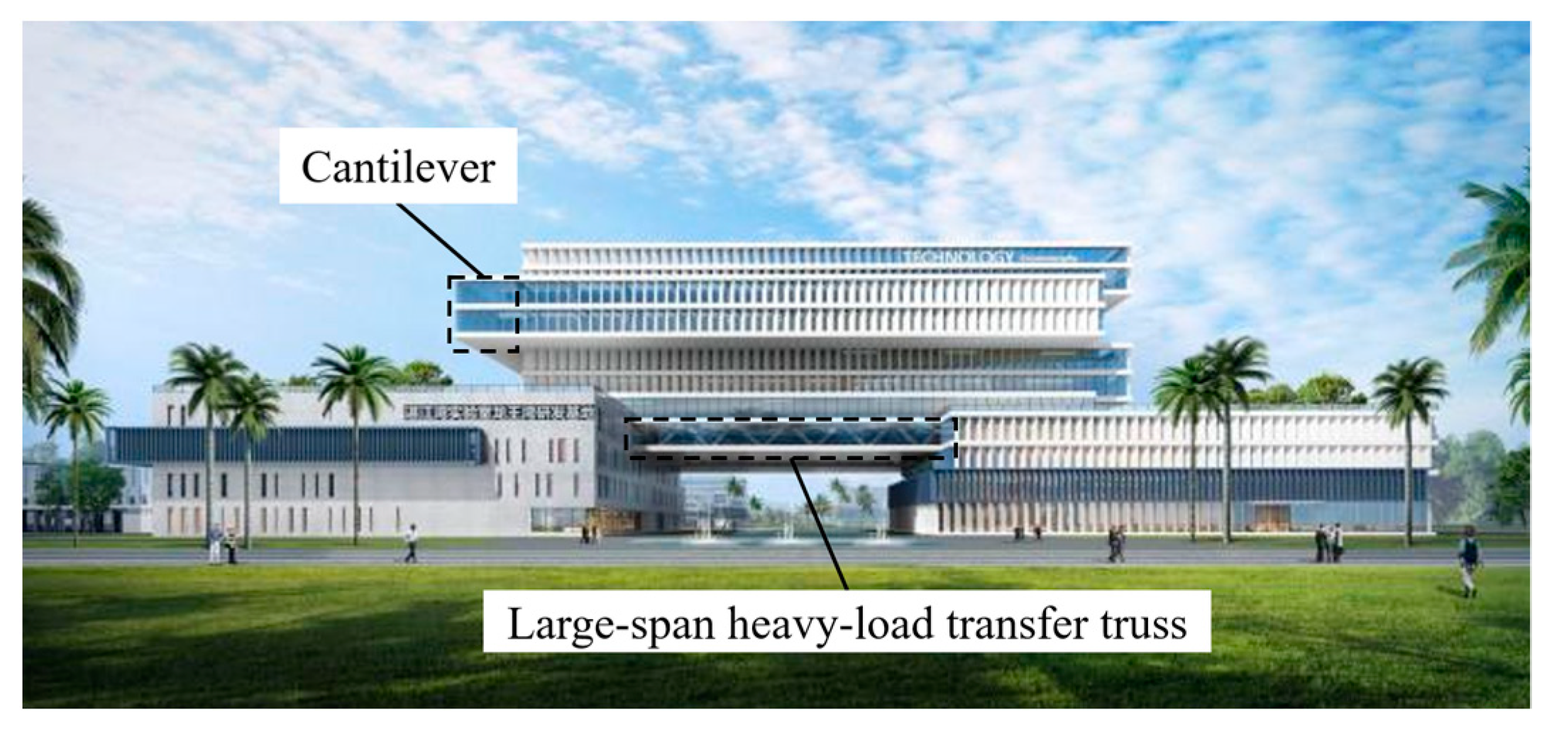
The R&D building project of the Zhanjiang Bay Laboratory is located in Potou District, Zhanjiang, Guangdong Province. The R&D building includes Zone I, Zone II, and Zone III, with a total floor area of about 67,000 m
2. Zone II is a high-rise main building structure, while Zone I and Zone III belong to podium buildings. The building area of Zone II of the R&D building is approximately 37,000 m
2. The architectural effect of the R&D building is shown in
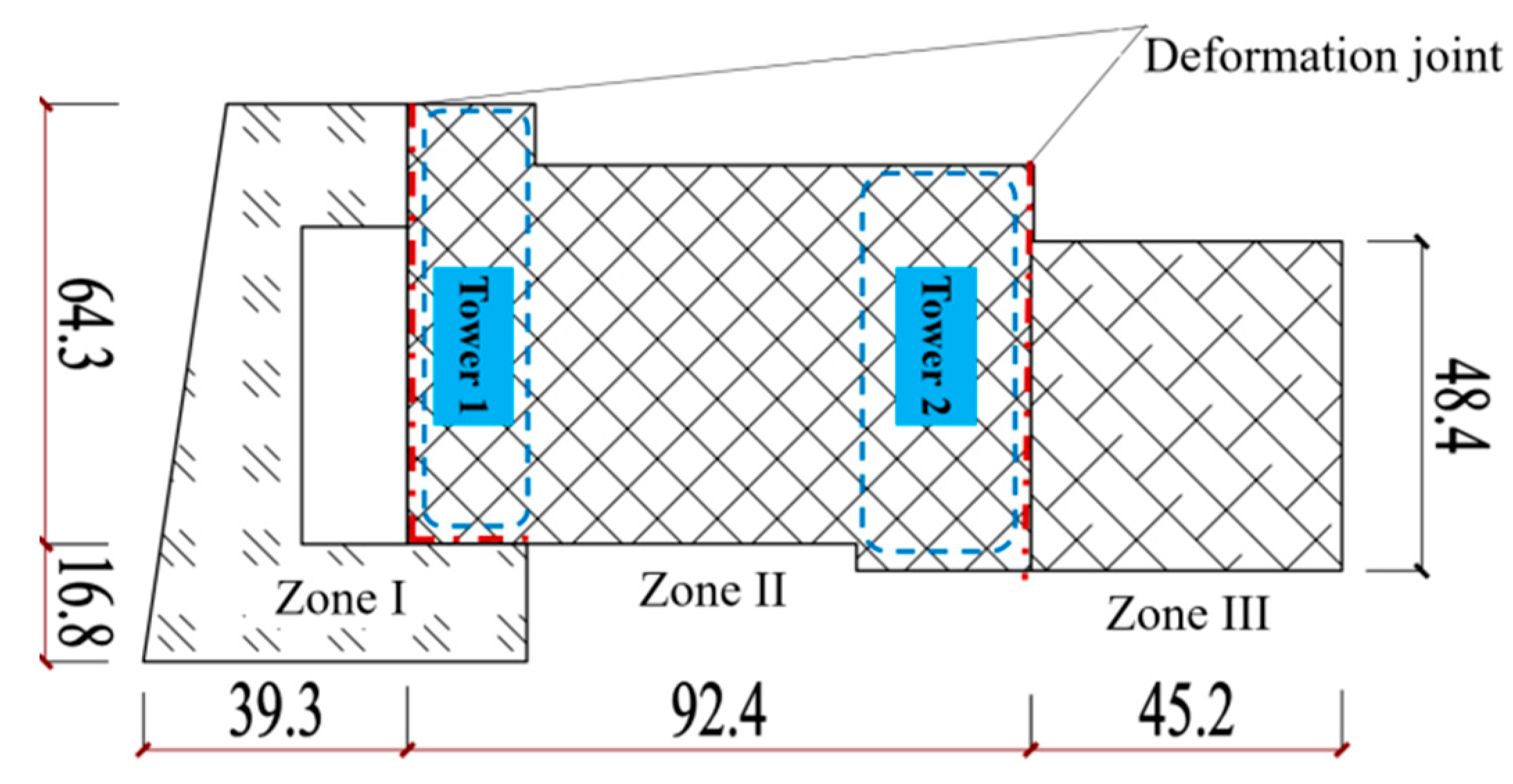
Figure 1. Zone II of the R&D building has 11 floors above the ground and one floor underground. The main structure of the core tube has 10 floors above the ground, with an overall height of 46.5 m. The 11th floor is the equipment floor. Tower 1 and Tower 2 are on either side of Zone II. The large-span, heavy-load transfer truss is located on the fourth floor, with a length of 53.4 m. Zone II is equipped with cantilevers above the sixth floor, with consistent structural characteristics for each of the two floors. The maximum overhang width of Zone II reaches 8.25 m. The plane partition of the R&D building is shown in
Figure 2.
Zone I and Zone III of the R&D Building have four floors above the ground and one floor underground, with a height of 19.45 m above ground. The floor heights of Zone I and Zone III are not high, and there is no special structure. Hence, a reinforced concrete frame structure was adopted. There are two reasons for the installation of deformation joints between Zone II and Zone I of the R&D Building, as well as between Zone II and Zone III. On the one hand, the height of Zone II is 2.4 times that of Zone I and Zone III. The height difference between the zones can cause an uneven settlement of the structure. By being separated by deformation joints, Zone I, Zone III, and Zone II can settle separately without affecting each other. On the other hand, the overall structure of the R&D Building is too long in the longitudinal direction. The structure is prone to torsional deformation. Therefore, setting deformation joints along Zone I, Zone III, and Zone II can avoid longitudinal torsional deformation of the structure.
3. System Comparison and Structural Design
3.1. Comparison and Selection of Structural Systems
Taking into account the overall building height, story height, column grid, load, and irregularities of Zone II, it is more suitable to choose steel structures. Compared with concrete structures, steel structures have a lower self-weight and better ductility. The use of steel structures is beneficial for the design of large-span transfer components. Steel, high-rise buildings generally adopt three structural systems: a steel frame structure, a braced steel frame structure, and a frame-core tube structure. In order to find the most suitable structural system for Zone II, it is necessary to analyze these three steel structure systems.
The steel frame structure relies solely on frame columns to resist lateral displacement. This results in weak lateral stiffness and contains a single line of defense against lateral loads. The frame columns would need to be enlarged to improve the structure’s lateral stiffness. This leads to a significant increase in steel usage and high costs. Therefore, this scheme is not recommended.
The braced steel frame structure includes frame columns and intercolumn bracings, providing two lines of defense against lateral loads. In the calculation model of the braced steel frame structure, a large-sized, cross-shaped bracing with a box section of 650 × 650 × 50 × 50 was arranged. However, the calculation results showed that the first mode of vibration still remained torsional. The stiffness ratio between the lower levels and the large-span, heavy-load truss floor is small. The shear capacity of the large-span, heavy-load truss floor is also limited. Increasing the size of the bracing sections to meet the requirements would not only be costly, but also reduce the usable space within the building. Hence, this scheme is not recommended.
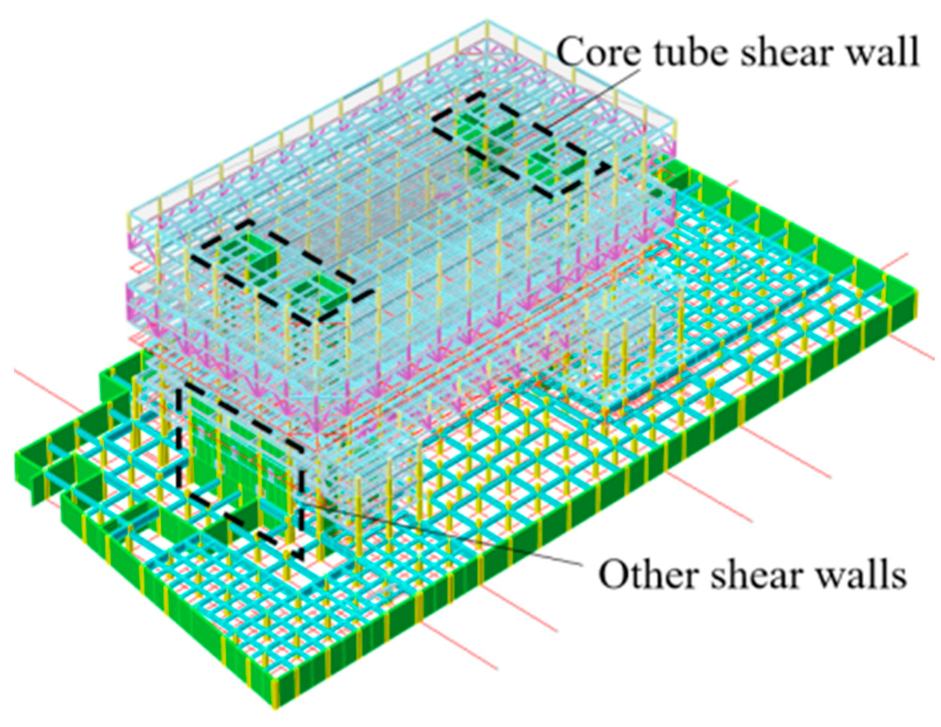
A frame-core tube structure system (see
Figure 3) is generally used in high-rise buildings. The periphery is a frame stress system composed of beams and columns, while the core tube is located in the middle of the structure. The frame-core tube structure system (see
Figure 3) features both frame columns and the core tubes as two lines of defense against lateral loads. The core tube supports the frame structure as the main load-bearing element. The core tube provides significant lateral stiffness and shear capacity to the entire structure. Therefore, only setting the core tube at the tower position is sufficient to meet the requirements. It not only improves the interlayer stiffness ratio, but also meets the requirements for shear bearing capacity. The frame-core tube structure system can not only reduce the amount of steel used, but also reduce the occupancy of building space.
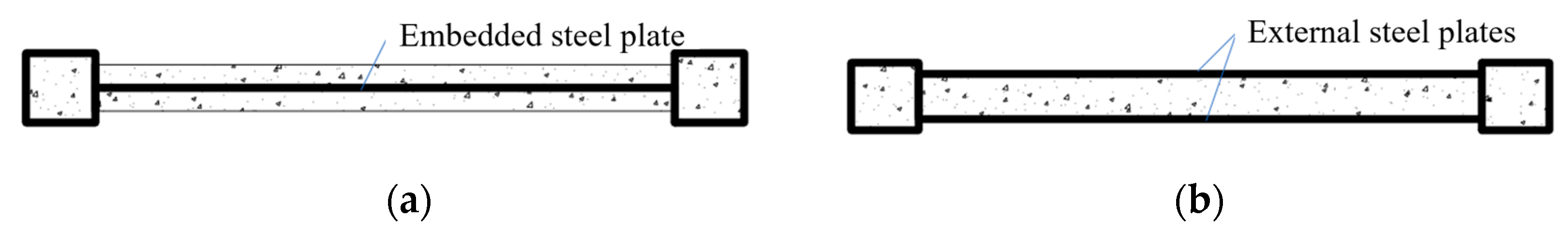
Two schemes were proposed for the design of the core tube shear wall structure: a concrete-embedded steel plate shear wall and double steel plate–concrete composite shear wall (see
Figure 4). The double steel plate–concrete composite shear wall [
9] refers to the wall structure formed by filling concrete between two steel plates. After calculating the two schemes, the lateral resistance of the double steel plate–concrete composite shear wall was better. Therefore, the core tube adopts a double steel plate–concrete composite shear wall structure.
In summary, considering the rationality of the structure, the satisfaction of functional requirements, and economic factors, the frame-core tube structure system is more suitable for the selected structural unit.
3.2. Performance Target Setting for Structures
According to the key technical points and implementation rules for the special review of the seismic fortification of high-rise building projects beyond the limit [
10,
11], the height of the R&D building project does not exceed the limit. However, there are multiple irregularities, such as stiffness mutations, torsional irregularities, size mutations, component discontinuities, complex connections, and multiple repetitions.
Based on the structural type and irregularity of this project, a performance-based seismic design method was adopted. Combining the reference indicators [
12] in the Code for Seismic Design of Buildings for achieving seismic performance requirements of structural components, the seismic performance target of this structure was based on level C. Due to the possibility of continuous structural damage caused by the failure of key components, the seismic performance target of key components was raised to level B. Level B indicates that the structure is basically intact during moderate earthquakes and slightly damaged during large earthquakes. Level C indicates that the structure is slightly damaged during moderate earthquakes and moderately damaged during large earthquakes. The limit value of the interstory displacement angle for a small earthquake is 1/800, and it is 1/100 for a large earthquake. The seismic performance design targets of components are shown in
Table 1.
3.3. Design of Diagonal Pull Rods
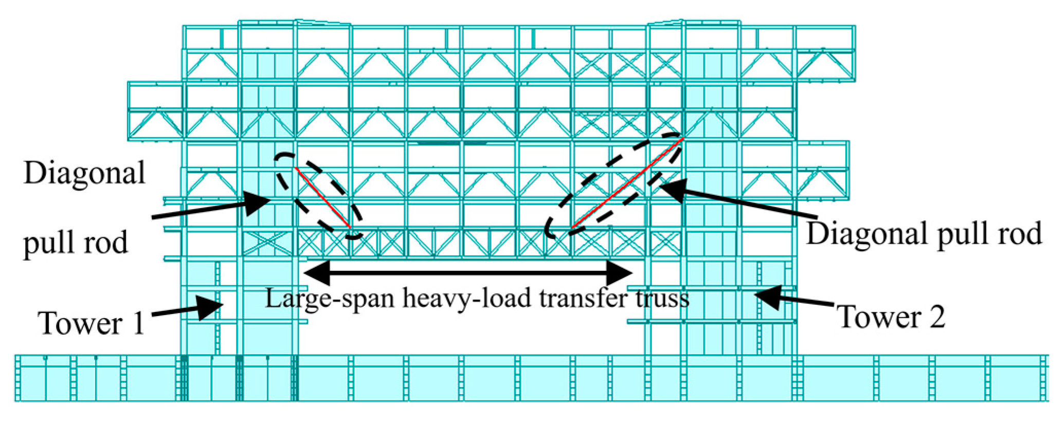
Due to the vertical discontinuity of the frame columns, it may lead to structural instability. Therefore, the 53.4 m long span heavy-load transfer truss is arranged on the four floors above the ground. The stiffness of the large-span, heavy-load transfer truss is very high. In addition, the large-span, heavy-load transfer truss is rigidly connected to the towers on both sides. The large-span, heavy-load transfer truss not only enhances the structural stiffness, but also controls the deflection of the truss layer. The core tube shear wall in the tower extends upwards to the 10th floor above ground (see
Figure 3), while other shear walls extend to the third floor above ground.
Eight diagonal pull rods are set horizontally between the shear wall of the core tube of the tower and the large-span, heavy-load transfer truss. Four diagonal pull rods are set on each side of the tower. The upper end of the diagonal pull rods on Tower 1 is connected to the end column of the sixth floor core tube shear wall. The upper end of the diagonal pull rods on Tower 2 is connected to the end column of the seventh floor core tube shear wall (see
Figure 5). All the lower ends of the diagonal pull rods are connected to the nodes of the frame column and the upper chord of the large-span, heavy-load transfer truss. The diagonal pull rods reduce the calculated length of the large-span, heavy-load transfer truss. Therefore, the diagonal pull rods improve the stability and robustness of the large-span, heavy-load transfer truss.
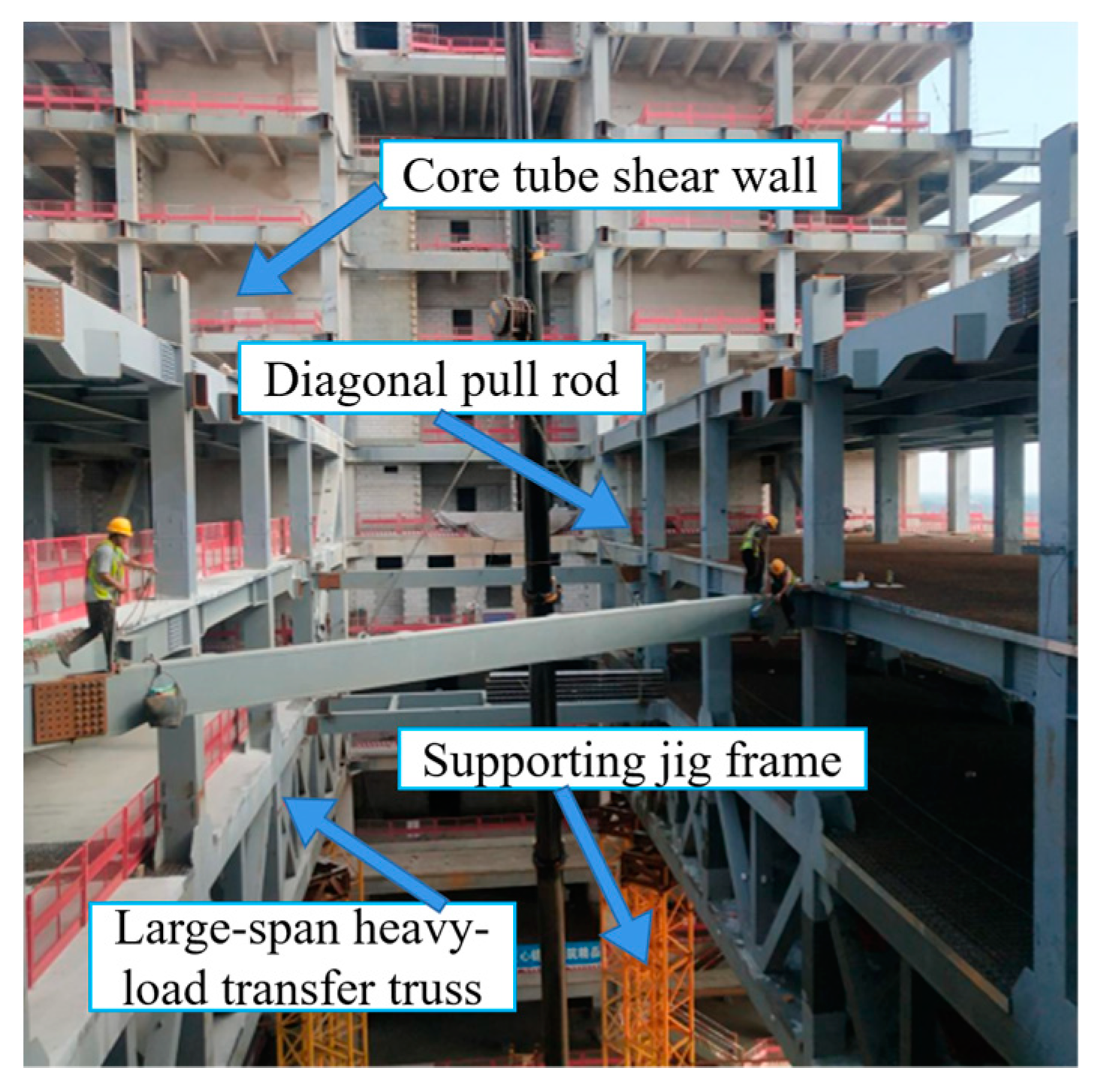
During the construction phase of the large-span, heavy-load transfer truss, a supporting jig frame (see
Figure 6) needs to be installed at the bottom of the large-span, heavy-load transfer truss. The supporting jig frame is a temporary support. The supporting jig frame will be removed after the completion of the large-span, heavy-load transfer truss. The supporting jig frame will transfer the load to the basement, causing certain damage to the basement floor. The diagonal pull rods connect the large-span, heavy-load transfer truss and the core tube shear walls. Therefore, the diagonal pull rods can transfer some of the load to the core tube shear walls, and then to the foundation, ultimately leading underground. In short, the diagonal pull rods can support the large-span, heavy-load transfer truss. Hence, the diagonal pull rods can reduce the deflection of the truss and also reduce the impact of construction loads on the basement floor.
An earthquake is a sudden and highly destructive natural disaster. Rare, large earthquakes can even cause irreparable damage to high-rise buildings, resulting in significant casualties and economic losses. Therefore, energy dissipation and a seismic reduction design for high-rise buildings are crucial for the seismic design. In this structure, the diagonal pull rods serve as metal dampers to consume seismic energy. During normal use, the diagonal pull rods use Q460 box sections with larger cross-sectional dimensions of 600 × 600 × 45 × 45. The diagonal pull rods have a higher strength grade and greater stiffness than the chord and web members of the truss. Under seismic loads, the diagonal pull rods can provide staged energy dissipation. When the structure is subjected to static loads, small earthquakes, and moderate earthquakes, the seismic energy is mainly dissipated by the less stiff chord and web members of the truss. The diagonal pull rods do not yield. When the structure is subjected to large earthquakes, most of the load is borne by the eight diagonal pull rods. The diagonal pull rods absorb most of the seismic energy and yield, thereby protecting the frame columns and beams.
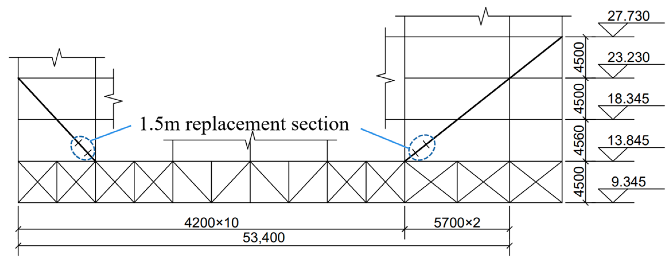
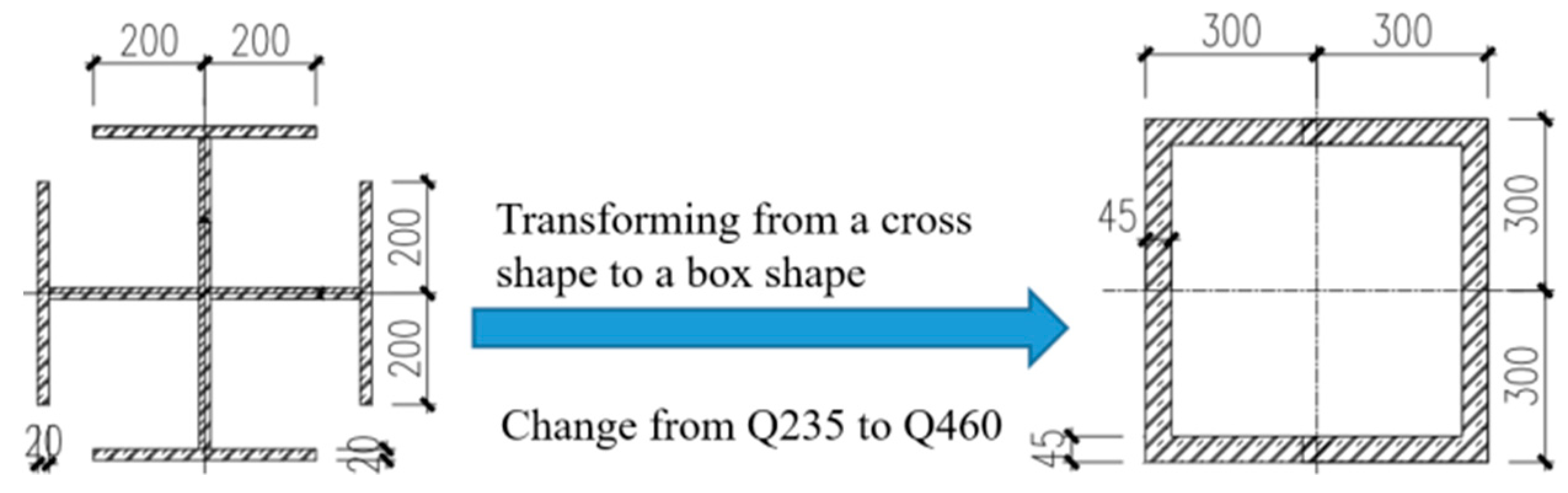
The length of the replacement section for the diagonal pull rod is 1.5 m. The replacement section is set at the bottom of the fifth floor (see
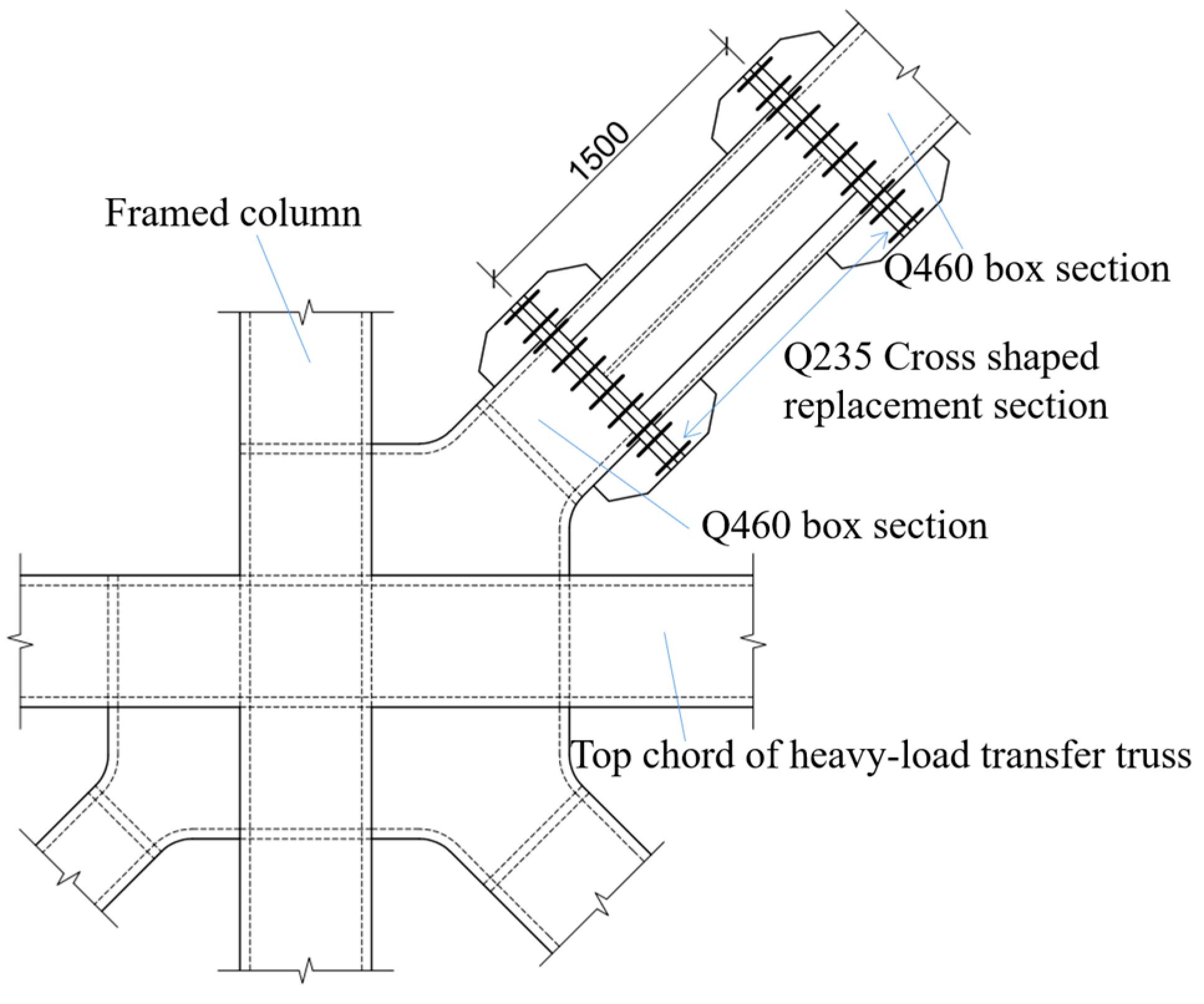
Figure 7) to facilitate manual disassembly and replacement. Before the replacement of the diagonal pull rod section, the diagonal pull rod consists of a Q460 box-shaped section and a Q235 cross-shaped replacement section (see
Figure 8). Compared with box-shaped, cross-sectional members, cross-shaped, cross-sectional members have poor torsional performance and deform faster under high axial compression ratios. Under the action of construction loads, the plastic deformation of diagonal pull rods mainly occurs in the cross-shaped section. The Q235 cross-shaped replacement section and the Q460 box-shaped section are connected by flanges. Multiple stiffeners are set at the connection nodes to meet the design requirements of “strong nodes, weak components”. In addition, this type of connection is easy to disassemble and replace diagonal pull rods. After the construction reaches the top layer, the diagonal pull rod is replaced with a new replacement section (see
Figure 9). The replaced diagonal pull rod consists of three Q460 box-shaped sections. Flange connections are still used between the box-shaped sections.
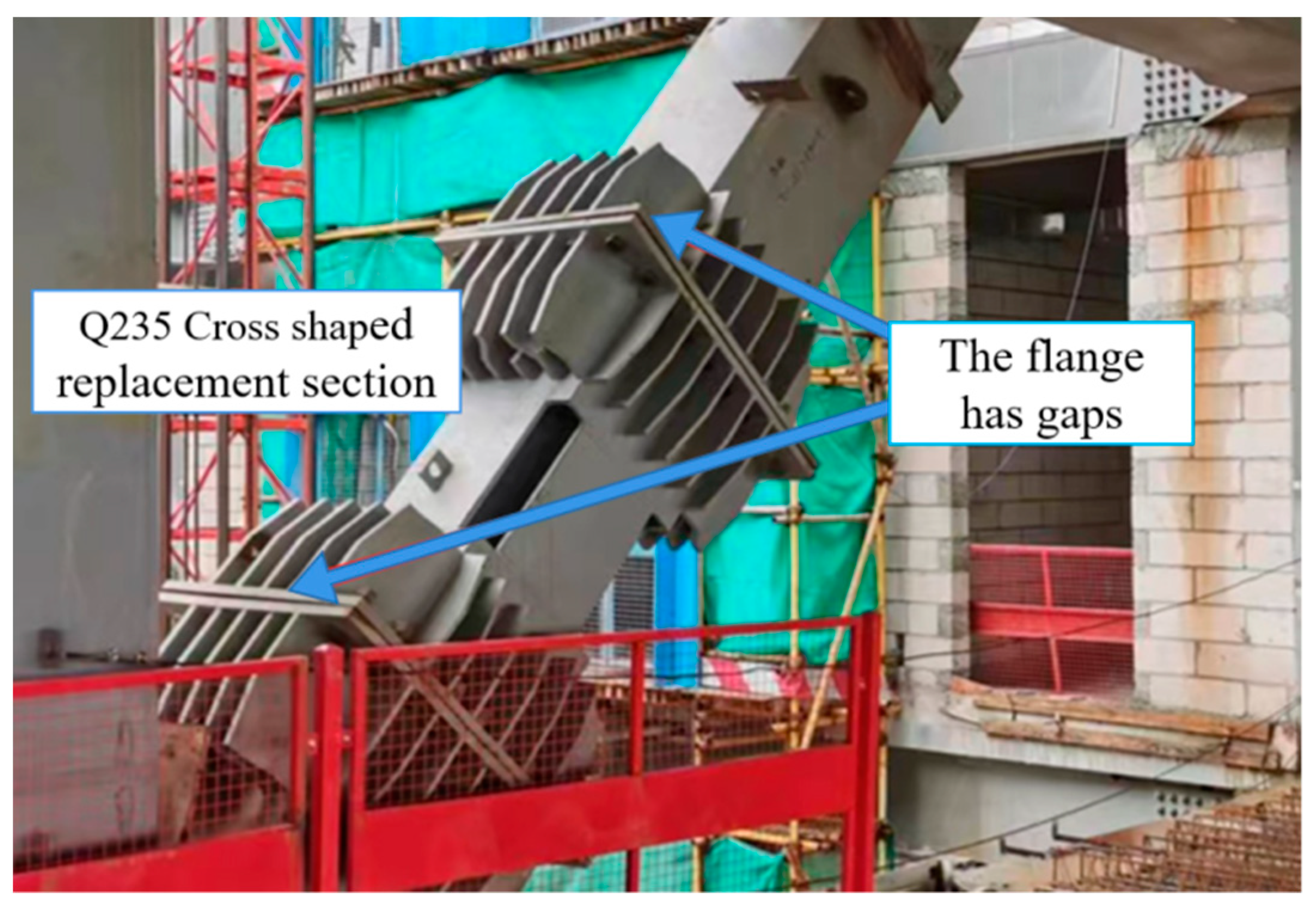
The traditional construction scheme of the step-by-step construction and dismantling is simulated using Midas Gen. During the construction phase, the load is taken as 1.0 times the self-weight. The stiffness of the floor slab is not considered. After completing the construction of the sixth floor above ground, the diagonal pull rod is installed. At this time, the axial force on the diagonal pull rods is relatively small. After dismantling the supporting jig frame at the bottom of the large-span, heavy-load transfer truss, construction began on floors 7–11. At the same time, the self-weight of the structure continues to increase, and the axial force on the diagonal pull rod is increasing. The Q235 cross-shaped replacement section yields first due to its yield strength being less than the Q460 box-shaped section. The Q235 cross-shaped replacement section undergoes deformation and elongation in length. There are large deformation gaps between the flange plates (see
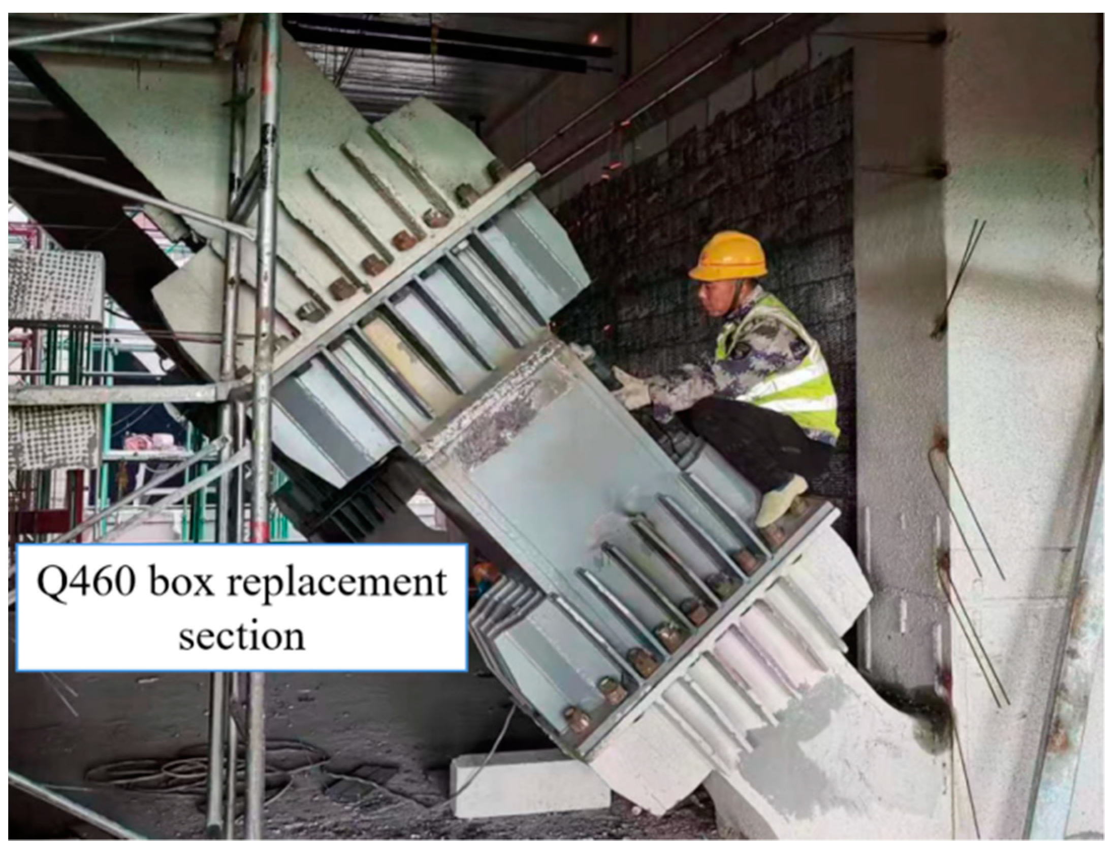
Figure 10). After the completion of the top layer of the structure, the Q235 cross-shaped replacement section that has already yielded and deformed is replaced with a suitable length Q460 box-shaped section (see
Figure 11). This replacement process releases the stress of the diagonal pull rod. At this time, the axial force of the diagonal pull rod is relatively small.
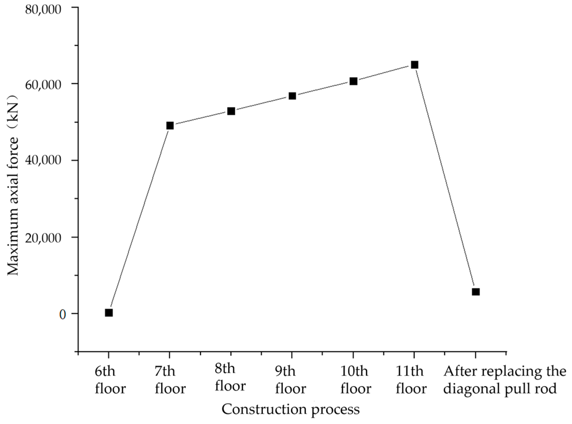
Figure 12 shows the maximum axial force of the diagonal pull rod during construction. The maximum axial force after installation and replacement of the diagonal pull rod is almost at the same level. It indicates that the degree of stress released from the diagonal pull rod is relatively high.
The installation of diagonal pull rods takes into account the impact of gravity load on the components during the construction process. The method of dismantling and replacing the Q235 cross-shaped replacement section can reduce the stress and damage caused by construction load on the diagonal pull rods. The robustness and safety redundancy of large-span, heavy-load transfer trusses also increase accordingly.
4. Seismic Calculation and Analysis of Structures
4.1. Elastic Analysis of Small Earthquakes
There are multiple irregularities in Zone II of the Zhanjiang Bay Laboratory R&D Building, such as sudden stiffness changes, torsional irregularities, size changes, component discontinuities, complex connections, and multiple repetitions. However, diagonal pull rods and large-span, heavy-load transfer trusses can mitigate these irregular effects. During small earthquakes, elastic analysis can ensure that these complex structural components are elastic.
4.1.1. Small Earthquake Response Spectrum Analysis
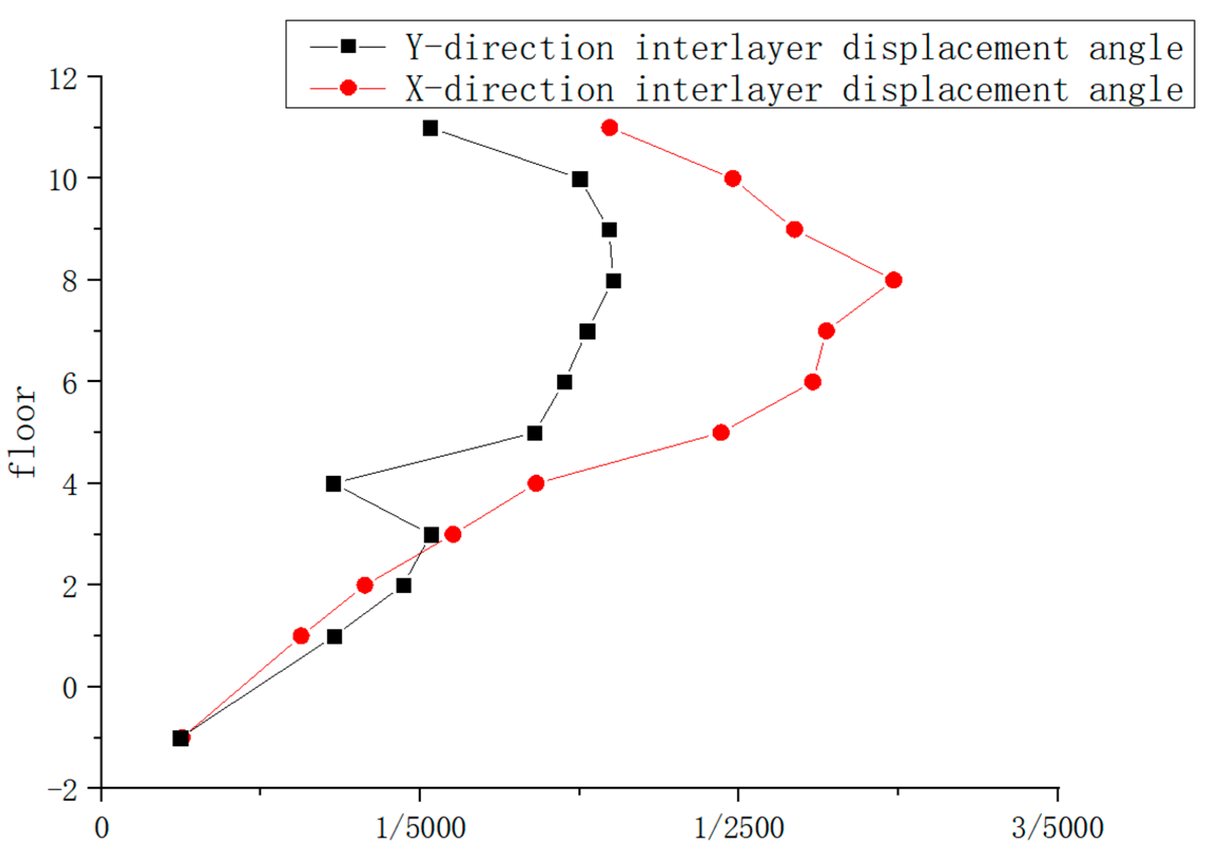
The structure is analyzed using vibration mode on the chemical decomposition spectrum during small earthquakes. The maximum interstory drift angle in the X direction is 1/3115, and in the Y direction, it is 1/2012 (see
Figure 13). The structure satisfies the elastic interstory drift angle limit of 1/800 [
12]. The maximum inter-story drift angles in both the X and Y directions occur on the eighth floor due to the larger area of staggered cantilever structures and resulting larger eccentricity. In addition, the Y-direction interstory drift angle on the fourth floor is small. It indicates that the large-span, heavy-load transfer truss has a high stiffness.
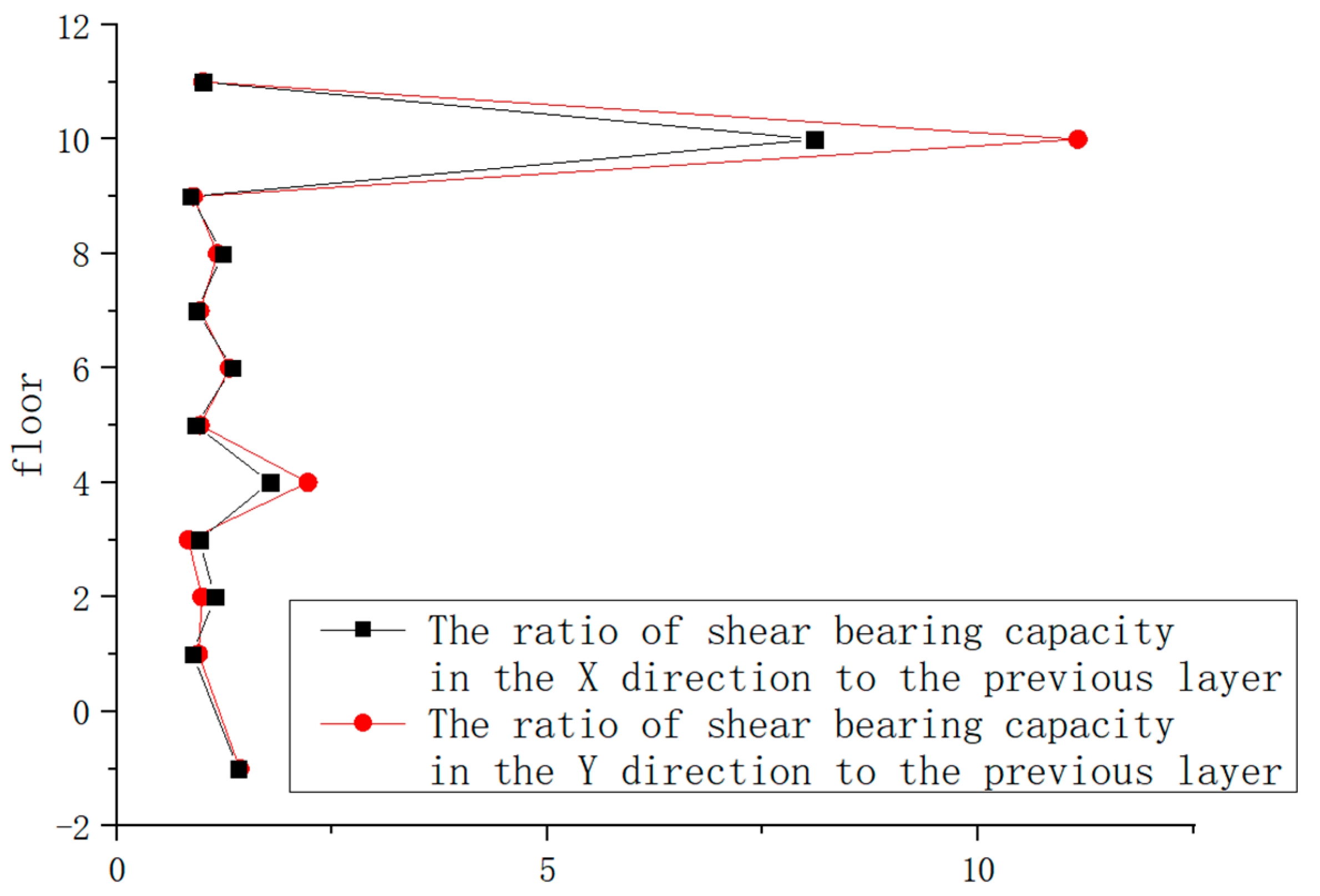
The ratios of the shear bearing capacity of each floor in the X and Y directions to the previous floor are above 0.8 (see
Figure 14). It meets the requirements [
13] of the Technical Specification for Steel Structure of Tall Building. It is thought that there is no sudden change in the floor bearing capacity of the structure. The ratios of the shear bearing capacity of the 4th and 10th floors to those of the previous floor are greater than those of the adjacent floors. All box section frame columns on the first to fourth floors are filled with concrete. Only the shear wall end columns above the fourth floor are filled with concrete. Therefore, the shear bearing capacity of the fourth floor is greater than that of the previous floor. The 11th floor is equipped with very few columns as the equipment layer. Due to the small number of frame columns, the shear bearing capacity of the 11th floor is relatively low. Therefore, the ratio of shear bearing capacity between the 10th layer and the previous layer is very large.
4.1.2. Elastic Time–History Analysis
YJK is used for small earthquake elastic time–history analysis, with five sets of natural waves and two sets of artificial waves as seismic inputs. Each wave met the requirements of the Code for Seismic Design of Buildings for effective peak value, duration, spectral characteristics, and base shear force [
12]. The elastic time–history analysis during small earthquakes is conducted based on a seven-degree earthquake and a Class III site. The maximum acceleration in the main direction is 35.000 cm/s
2, and the secondary direction is 29.750 cm/s
2. According to the analysis of seven sets of seismic waves, the interstory drift angle of the structure is the largest under the action of the Chi-Chi, Taiwan-06_NO_3278 earthquake wave. The maximum interstory drift angle in the X direction is 1/1801, and in the Y direction, it is 1/2072. Both meet the limit of 1/800 for elastic interstory drift angles.
4.1.3. Comparison between Response Spectrum Analysis and Time–History Analysis
Comparing the structural base shear force calculated by the response spectrum method and the time–history analysis method, the difference between the average bottom shear forces calculated by the response spectrum method and multiple time–history curves is less than 20% (see
Table 2). It conforms to the provisions [
13] on the elastic time–history analysis in the Technical Specification for Steel Structure of Tall Building, and it can be considered that the calculation results are relatively accurate.
Seven sets of time–history curves are input for the time–history analysis of the structure for calculation. The average value of the time–history calculation results and the larger values of the response spectrum calculation results can be used as the seismic effect of the structure. Therefore, designing the results of the response spectrum method as the seismic effect of the structure will tend towards safety. Using elastic analysis during small earthquakes, it was concluded that the structural stress is reasonable. All components can meet the seismic performance level design requirements.
4.2. Elastoplastic Analysis of Large Earthquakes
During a large earthquake, the stress–strain relationships of key components of the structure are no longer linear. Therefore, it is necessary to conduct a large earthquake elastic–plastic analysis of the structure. Dynamic elastic–plastic analysis is based on the dynamic equation of the structure [
14]. Using dynamic elastic–plastic analysis, the displacement and internal force of the structural components at each moment during the seismic action process can be obtained. At the same time, the order of yielding of the structural components and the location of stress concentration can be obtained. Finally, the weak parts of the structure and the damage level of the assessed structure can be obtained [
15].
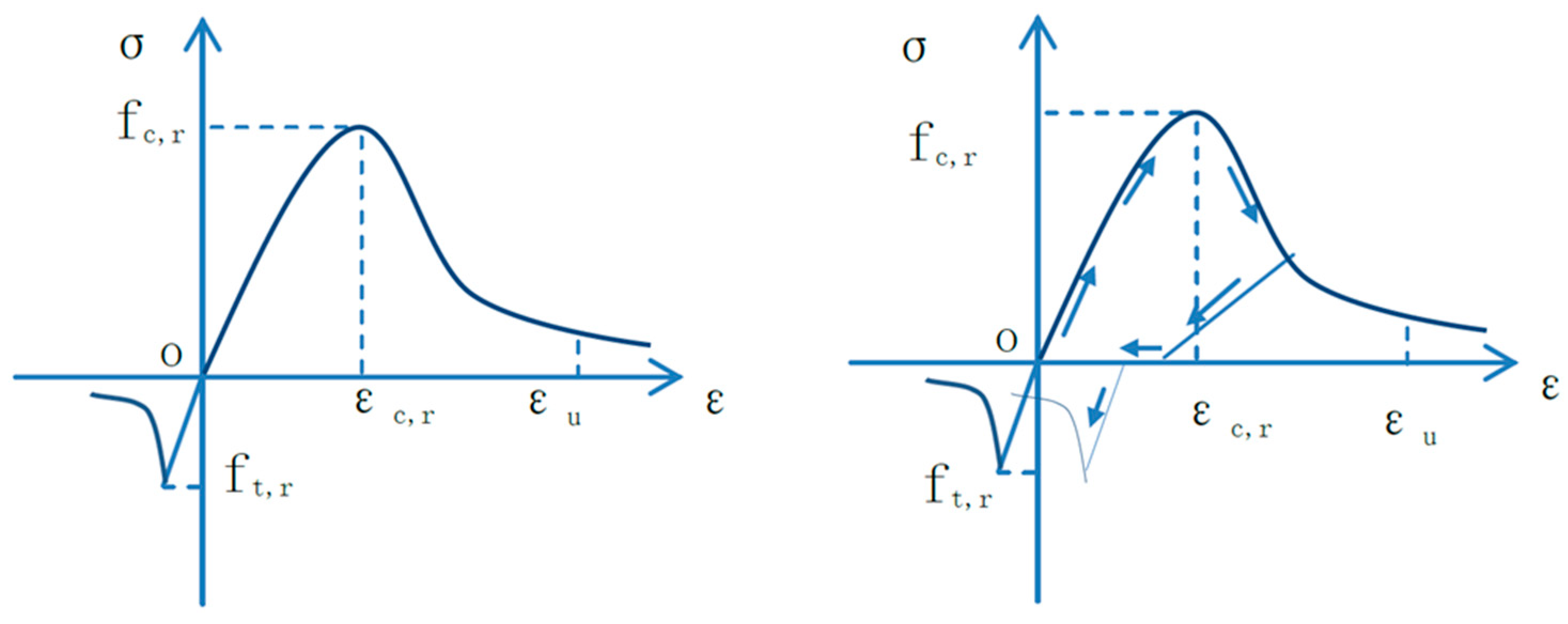
The structure adopts YJK to analyze the nonlinear response and seismic performance of the overall structure during large earthquakes. The fiber bundle model is used to simulate the members in the analysis model. The fiber bundle element can consider the coupling effects of axial force and the bending moment. The effect of each fiber is a combination of axial force and the bidirectional bending moment, and the wall elements are simulated using plate shell elements based on the concrete damage constitutive theory. Each unit uses nine Gaussian integration points for the numerical integration calculation. The concrete constitutive model uses the built-in concrete fiber uniaxial constitutive model in the program (see
Figure 15), while the steel material model uses the bilinear dynamic strengthening model (see
Figure 16). The damping adopts the classical Rayleigh damping. The damping matrix [C] is composed of a combination of the mass matrix [M] and the stiffness matrix [K]. The calculation formula is shown in Equation (1). The damping matrix remains constant throughout the entire solution process.
where ω
1 and ω
2 are the frequency values corresponding to the two periods used to calculate the damping coefficient, and ξ
1 and ξ
2 are the damping ratios for the corresponding periods.
According to the requirements of the Code for Seismic Design of Buildings [
12], the structure selects two natural waves, Big Bear-01_NO_908 and Chi-Chi, Taiwan-04_NO_2727, and an artificial wave, Artwave-RH3TG055, to conduct large earthquake elastic–plastic analysis. The effective peak acceleration is taken as 220.00 cm/s
2 in the main direction and 187.00 cm/s
2 in the minor direction, according to the code. The calculation results indicate that the dynamic response of the structure during the action of the natural wave, Chi-Chi, Taiwan-04_NO_2727, is relatively large. Therefore, the calculation results of natural waves Chi-Chi, Taiwan-04_NO_2727 are selected to carry out the bearing capacity analysis, damage level analysis, and energy consumption analysis of the structure during large earthquakes.
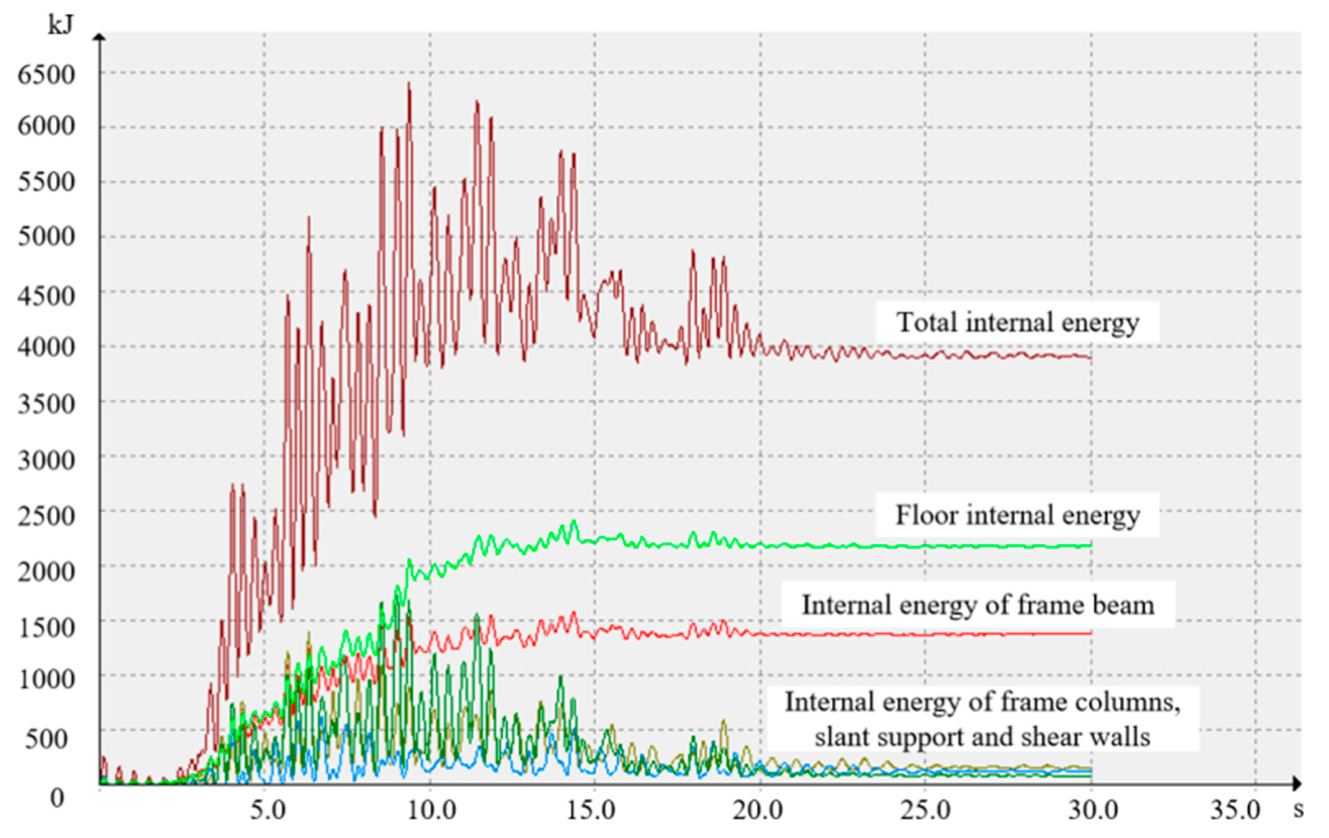
Figure 17 shows the tensile damage levels of individual components, and
Figure 18 shows the structural energy curves.
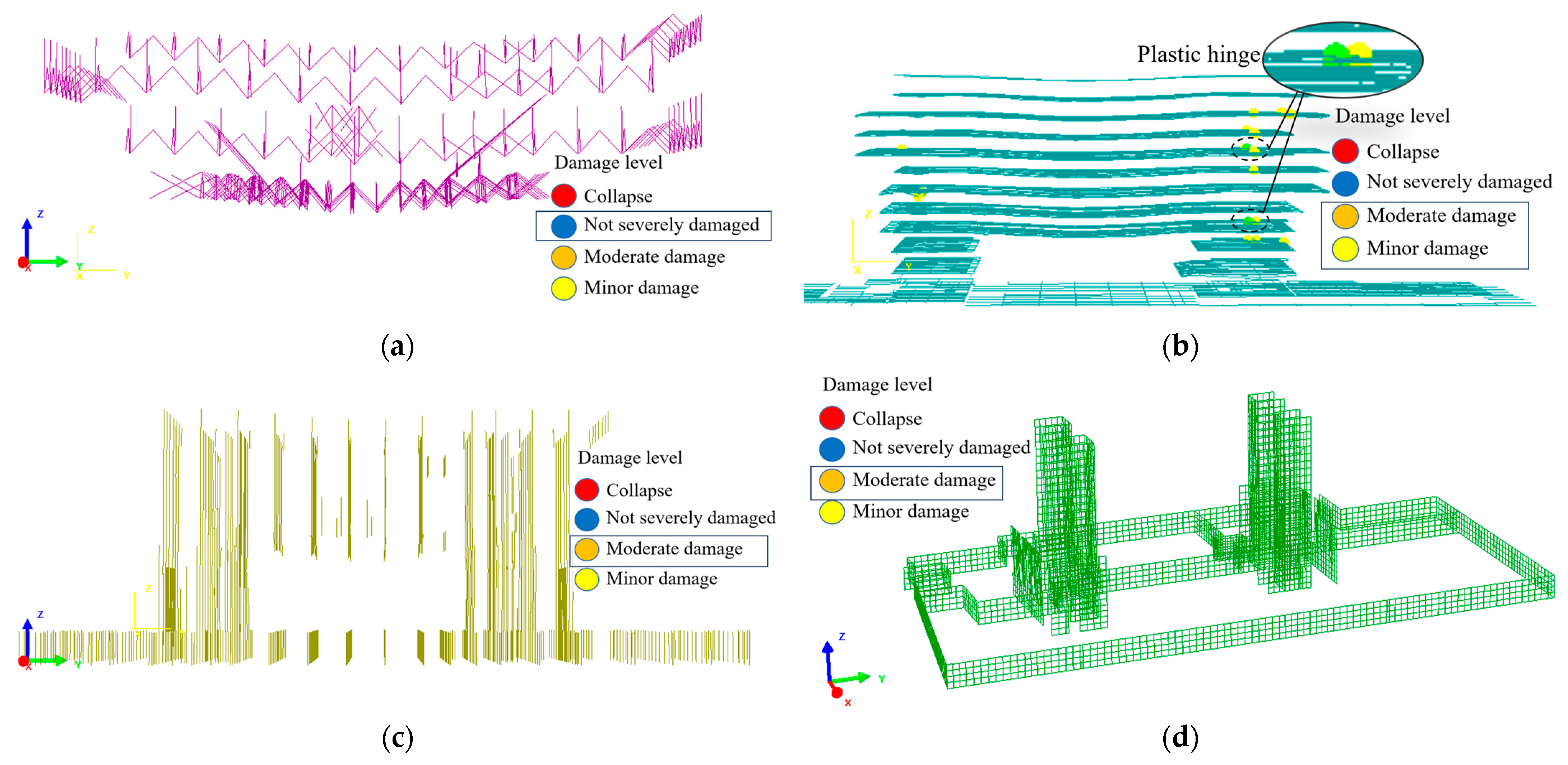
The criteria [
16] for determining the seismic damage levels of structural components refer to the Design Code for Collapse Resistance of Building Structures. The classification of earthquake damage levels is based on strains. Under the working condition of the seismic wave Chi-Chi, Taiwan-04_NO_2727, according to the tensile damage levels of individual components in
Figure 17c,d, the damage levels of column components and shear walls are moderate damages. During large earthquakes, the damages to the frame columns and shear walls as vertical components are minimal. Hence, the structure will not collapse under the support of vertical components. According to
Figure 17a, the damage levels of supporting components (including large-span, heavy-load transfer truss and cantilever trusses) are relatively high, but there are no plastic hinges. During large earthquakes, the displacements of large-span, heavy-load transfer trusses and cantilever trusses are relatively large, but the supporting components do not yield. From the tensile damage level of the beam components in
Figure 17b, plastic hinges appear at the position of the frame beams on both sides of the towers. The local damage levels of the frame beams reach moderate damages. Therefore, the frame beams as energy dissipation components yield earlier than key components, such as shear walls, large-span, heavy-load transfer trusses, and cantilever trusses.
From an energy perspective, the structural components with higher internal energy are the floor slabs as secondary components and the frame beams as energy dissipation components (see
Figure 18). During large earthquakes, concrete floor slabs and frame beams consume most of the seismic energy. It leads to cracking and failure of the concrete floor slabs. The frame beam yields before other components, which conforms to the principle of “strong columns and weak beams”. However, the internal energy of the shear wall, frame column, and slant support are very small. During large earthquakes, almost all members, such as the frame column, shear wall, cantilever truss, and large-span, heavy-load transfer truss have not yielded. The key components did not yield during a large earthquake. This ensures that the overall structure does not collapse during strong earthquakes. During large earthquakes, the order of energy consumption of structural members from high to low is the floor slab, frame beam, cantilever trusses, large-span, heavy-load transfer truss, frame column, and shear wall. The order of energy consumption of structural members is negatively correlated with the degree of importance. Consequently, the structure has a reasonable yield mechanism. This yield order allows the structure to consume more energy before its collapse. This yield mechanism is safer and more suitable for structural seismic resistance.
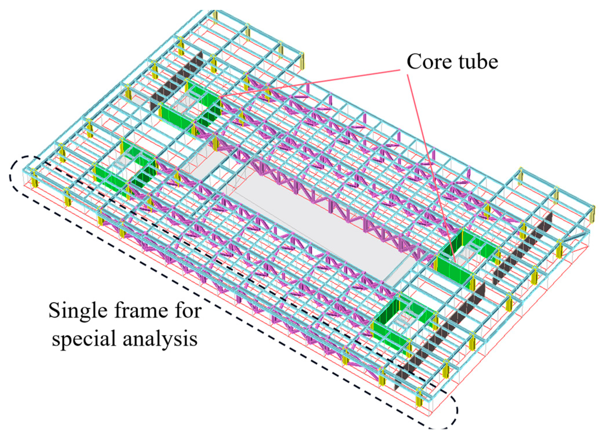
5. Special Analysis of Single Frame Structures
During large earthquakes, concrete floor slabs may experience cracking and failure. At this point, the out-of-plane constraint effect of the frame in the overall structure is reduced. In this special environment, the mutual supports between individual frames are very weak. Therefore, a special analysis of a single frame structure that ignores the out-of-plane constraint effect should be conducted. The calculation results of the single frame structure tend to be conservative, and the structural safety can be better ensured.
The outermost frame in the overall structure does not have the support of the core tube or the diagonal pull rod. The outermost frame of the overall structure has the lowest stiffness, while the outermost frame is the most prone to failure. Therefore, this frame was selected for the analysis of a single frame structure (see
Figure 19).
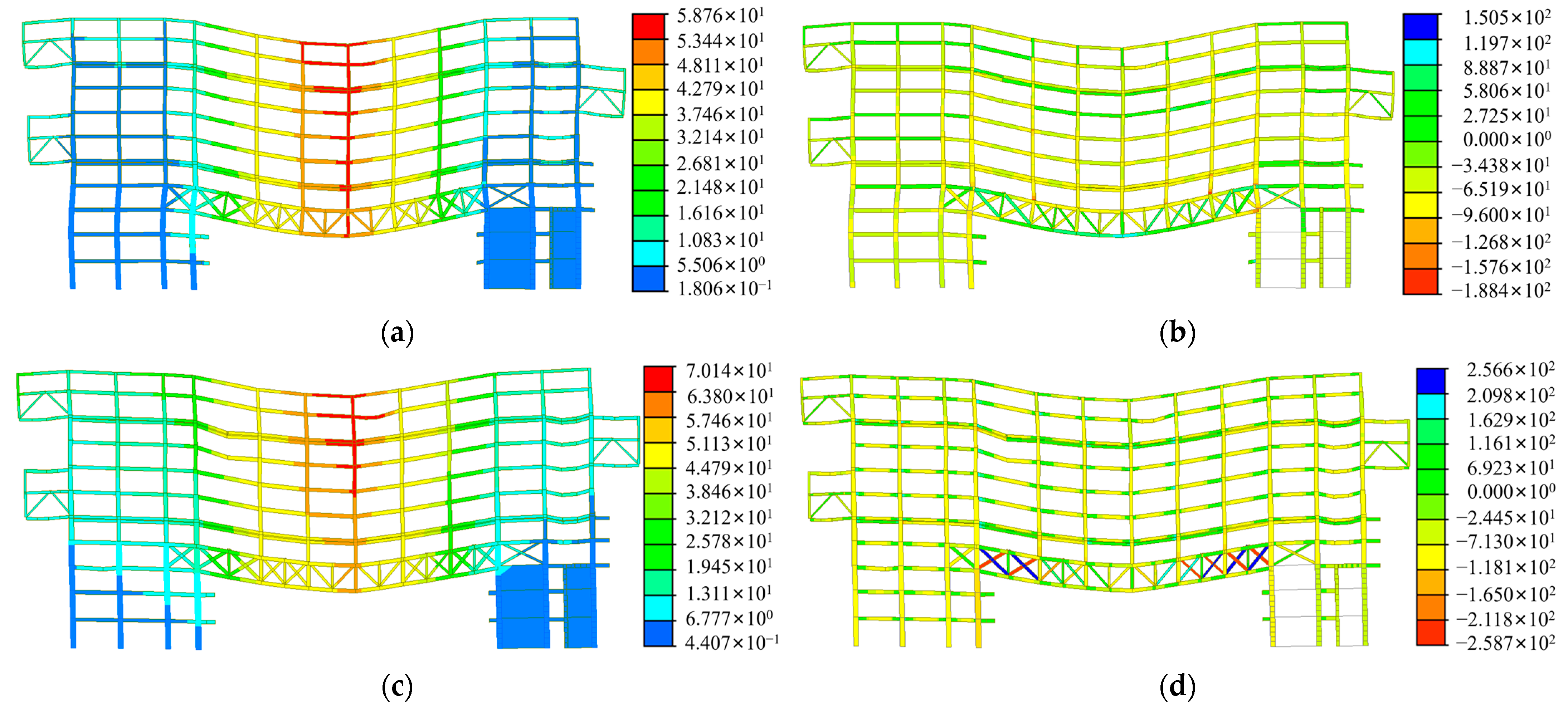
Figure 20a,b show the stress and displacement of the frame obtained from the overall structural analysis.
Figure 20c,d show the stress and displacement of the frame using a separate analysis. A single frame analysis is used to simulate the failure of floor slabs.
5.1. Load Conditions on the Frame
From previous research (see
Figure 18), it can be seen that the floor is the first to fail. After all the floors are removed from work, each frame is almost working independently. Therefore, it is necessary to study the response of a single frame under load combinations. According to relevant studies [
17,
18], steel frame beams are mainly subjected to torsion and shear forces. In a finite element simulation, steel frame structures are subjected to dead loads, live loads, wind loads, and vertical and horizontal seismic loads. The calculation of multiple load combinations for the structure has been completed. The maximum response of a single frame structure occurs under the standard combination of constant and live loads.
The bottom of the single frame structure is rigidly connected, and external constraints are ignored. The constant and live loads of the floor in the overall structure are distributed to the frame beams and shear walls of the single frame structure. The loads on the beams and walls are considered as the constant and live loads for the analysis of the single frame structure. Wind loads are calculated based on the wind loads on the single frame structure without considering the transfer of forces in the overall structure. The seismic load conditions remain unchanged.
5.2. Response of a Single Frame under Load Combinations
Under the standard combination of constant and live loads, the maximum displacement of the frame in the overall structure is 58.8 mm, the maximum stress is 180.6 MPa, and the maximum deflection-to-span ratio is 1/905. The maximum displacement of a single frame structure is 70.1 mm, the maximum stress is 258.7 MPa, and the maximum deflection-to-span ratio is 1/762. The limit value of deflection-to-span ratio refers to the maximum value of the deflection-to-span ratio under ensuring structural stability. The allowable deflection [
19] of the main beam or truss under permanent and variable load standards is L/400. Therefore, the outermost frame meets the deflection-to-span ratio limit of 1/400 in the Steel Structure Design Standard, both with and without considering out-of-plane constraints. Even without considering out-of-plane constraints, the structure can still meet the requirements. In fact, even if the floor slab is completely destroyed, the out-of-plane constraints do not all disappear. Hence, the safety redundancy of the structure is relatively high.
For the same frame, the maximum displacement and maximum stress of a single structure have increased by 19.2% and 43.2%, respectively, compared to the overall structure. Compared with the overall structure, a single frame structure has no out-of-plane constraint effect. Therefore, in standard combination loads, the stress and displacement are both greater.
In summary, the displacement, bearing capacity, and member stress ratio of a single structure can still meet the requirements without external support and with a complete degradation of floor stiffness. Therefore, the structure has good mechanical performance and high safety.
6. Conclusions
The seismic design of the large-span, heavy-load transfer truss of the Zhanjiang Bay R&D Building has been carried out, and the following conclusions can be drawn.
(1) The frame-core tube structure system had a strong resistance to lateral deformation. This structure was beneficial for resisting horizontal seismic loads.
(2) The installation process of the diagonal pull rods took into account the impact of construction loads on the components. This consideration was closer to the actual situation. The method for replacing the Q235 cross section can reduce the stress and damage of the diagonal pull rods caused by construction load.
(3) The structure adopted a performance-based seismic design method, and seismic analysis was conducted using the Midas Gen 2022 and YJK 5.0 software. During small earthquakes, all structural components were in the elastic stage. The structural stiffness was sufficient to prevent damage during small earthquakes. The loads of small earthquakes were not large, but the frequency was high. Therefore, maintaining the elasticity of the structure during small earthquakes was necessary for the long-term use of buildings. During large earthquakes, frame beams, such as energy dissipation components, yielded first, but vertical components, such as frame columns and core tubes, did not yield. Hence, the structure did not collapse under the support of vertical components.
(4) The deflection and member stress of the single structure met the requirements without considering the external constraints and the transmission of force in the overall structure. In addition, the calculation results of the single structure were more conservative and had a higher safety redundancy than the overall structure.
7. Possible Directions for Future Studies
Taking the research and development building project of the Zhanjiang Bay Laboratory as the engineering background, this article studied the seismic performance under the combined actions of diagonal pull rods and large-span, heavy-load transfer truss. Due to the limitations of Midas modeling, the flange plate for the replacement section of the diagonal pull rod was not established. Therefore, the impact of replacing segment nodes on structural seismic resistance cannot be considered.
In the future, more in-depth research can be conducted on the impact of diagonal pull rod details on seismic performance. The local model of the diagonal pull rods should be established. Replacing segment nodes, flange plates, and bolts should all be considered. These details will affect the performance of diagonal pull rods during earthquakes. Therefore, this direction is worth exploring and researching.
Author Contributions
Writing—original draft, T.L.; software, M.L.; investigation, C.X. and D.L.; methodology, R.L.; All authors have read and agreed to the published version of the manuscript.
Funding
This study was supported by the CSSC International Engineering Co., Ltd. Technological Innovation and research and development project (CN), Award Number: 20MT01J and the CSSC International Engineering Co., Ltd. Technological Innovation and research and development project (CN), Award Number: 20MT07J.
Data Availability Statement
The data presented in this study are available in the article.
Conflicts of Interest
Authors Tao Lan, Ran Li, Chen Xue and Dongmei Liu were employed by the company CSSC International Engineering Co., Ltd. The remaining authors declare that the research was conducted in the absence of any commercial or financial relationships that could be construed as a potential conflict of interest. The authors declare that this study received funding from CSSC International Engineering Co., Ltd. The funder had no role in the design of the study; in the collection, analysis, or interpretation of data, in the writing of the manuscript, or in the decision to publish the results.
References
- Li, B. Research on the Influences of Transfer Truss on Seismic Behavior of High-Rise Building Structures; Tsinghua University: Beijing, China, 2016. [Google Scholar]
- Maclead, I.A. Shear Wall-Frame Interaction—A Design Aid; Portland Cement Association: Washington DC, USA, 1970. [Google Scholar]
- Gamayunova, O.; Vatin, N.I. Education in the field of construction of unique, high-rise and long-span buildings and constructions. Adv. Mater. Res. 2015, 1065–1069, 2459–2462. [Google Scholar] [CrossRef]
- Wang, X.; Yu, D.; Hand, W.; Chang, T. Key points on large-span and heavy-load transfer structure design of Project of China National Convention Center Phase Two. Build. Struct. 2021, 51, 7–12. [Google Scholar]
- Wand, X.; Yu, D.; Hand, W. Structural design of second-phase project of National Convention Center. Build. Struct. 2019, 49, 65–71. [Google Scholar]
- Cao, C.; Liao, Y.; Wu, J.; Li, H.; Chang, L. Design of large-span and heavy-load structure in high position zone of Sunac Snow Park in Guangzhou. Build. Struct. 2020, 50, 51–56. [Google Scholar]
- Peng, S.; Zhao, S. Comparison and selection of a conjoined structure scheme based on continuous collapse resistance analysis. Build. Struct. 2023, 53. (In Chinese) [Google Scholar] [CrossRef]
- Li, Z.; Guo, M.; Li, Y. Analysis of construction mechanical properties of novel large-span steel-concrete transfer truss of high-rise building during construction stage. Struct. Eng. 2020, 38, 152–160. [Google Scholar]
- Lan, T.; Wang, X. Analysis and application of double steel plate concrete composite shear wall in the R&D Building of Zhanjiang Bay Laboratory. Buildings 2023, accept. [Google Scholar]
- Technical Key Points of Special Review on Seismic Fortification of Out of Gauge High-Rise Buildings; JZ No. 67; Ministry of Housing and Urban-Rural Development: Beijing, China, 2015.
- Implementation Rules for the Special Review of Seismic Fortification of High-Rise Buildings Beyond Limits in Guangdong Province; Document No. 20; The Guangdong Provincial Department of Housing and Urban Rural Development: Guangzhou, China, 2016.
- GB 50011; Code for Seismic Design of Buildings. China Architecture & Building Press: Beijing, China, 2010.
- JGJ 99; Technical Specification for Steel Structure of Tall Building. China Architecture & Building Press: Beijing, China, 2015.
- Liu, H. The Static and Dynamic Elastic-Plastic Analysis of a High Building Structure; Southwest Jiaotong University: Chengdu, China, 2016. [Google Scholar]
- Wang, X.; Sun, Y.; Zhao, Y. Seismic design of Dunhuang Grand Theatre. Build. Struct. 2020, 50, 73–80. [Google Scholar]
- CECS 392; Design Code for Collapse Resistance of Building Structures. China Planning Press: Beijing, China, 2014.
- Pishro, A.A.; Zhang, Z.; Pishro, M.A.; Liu, W.; Zhang, L.; Yang, Q. Structural performance of EB-FRP-strengthened RC T-beams subjected to combined torsion and shear using ANN. Materials 2022, 15, 4852. [Google Scholar] [CrossRef] [PubMed]
- Pishro, A.A.; Zhang, S.; Zhang, Z.; Zhao, Y.; Pishro, M.A.; Zhang, L.; Yang, Q.; Postel, V. Structural behavior of FRP-retrofitted RC beams under combined torsion and bending. Materials 2022, 15, 3213. [Google Scholar] [CrossRef] [PubMed]
- GB 50017; Steel Structure Design Standard. China Architecture & Building Press: Beijing, China, 2017.
Figure 1.
Architectural rendering of the R&D building.
Figure 1.
Architectural rendering of the R&D building.
Figure 2.
Schematic diagram of the R&D building plane zoning (unit: m).
Figure 2.
Schematic diagram of the R&D building plane zoning (unit: m).
Figure 3.
Frame-core tube structure.
Figure 3.
Frame-core tube structure.
Figure 4.
The design of the core tube shear wall structure. (a) Concrete-embedded steel plate shear wall. (b) Double steel plate–concrete composite shear wall.
Figure 4.
The design of the core tube shear wall structure. (a) Concrete-embedded steel plate shear wall. (b) Double steel plate–concrete composite shear wall.
Figure 5.
Layout of diagonal pull rods.
Figure 5.
Layout of diagonal pull rods.
Figure 6.
Field view of diagonal pull rod.
Figure 6.
Field view of diagonal pull rod.
Figure 7.
Composition of diagonal pull rods.
Figure 7.
Composition of diagonal pull rods.
Figure 8.
Detailed drawing of diagonal pull rods.
Figure 8.
Detailed drawing of diagonal pull rods.
Figure 9.
Cross-sectional changes of the replacement section.
Figure 9.
Cross-sectional changes of the replacement section.
Figure 10.
Site view before replacing diagonal pull rods.
Figure 10.
Site view before replacing diagonal pull rods.
Figure 11.
Field diagram after replacing diagonal pull rods.
Figure 11.
Field diagram after replacing diagonal pull rods.
Figure 12.
The maximum axial force of the diagonal pull rod during construction.
Figure 12.
The maximum axial force of the diagonal pull rod during construction.
Figure 13.
Displacement angles between lower layers under earthquake actions.
Figure 13.
Displacement angles between lower layers under earthquake actions.
Figure 14.
Shear bearing capacity ratios of floors.
Figure 14.
Shear bearing capacity ratios of floors.
Figure 15.
Concrete skeleton curve and hysteresis curve.
Figure 15.
Concrete skeleton curve and hysteresis curve.
Figure 16.
Steel skeleton curve and hysteresis curve.
Figure 16.
Steel skeleton curve and hysteresis curve.
Figure 17.
Tensile damage levels of individual components. (a) Tensile damage levels of supporting components. (b) Tensile damage levels of beam components. (c) Tensile damage levels of column components. (d) Shear wall tensile damage levels.
Figure 17.
Tensile damage levels of individual components. (a) Tensile damage levels of supporting components. (b) Tensile damage levels of beam components. (c) Tensile damage levels of column components. (d) Shear wall tensile damage levels.
Figure 18.
Seismic wave internal energy curves.
Figure 18.
Seismic wave internal energy curves.
Figure 19.
Single frame for special analysis.
Figure 19.
Single frame for special analysis.
Figure 20.
Displacements and stresses of the same frame under the overall structure and single structure. (a) Maximum displacement of the overall structure. (b) Maximum stress of the overall structure. (c) Maximum displacement of a single structure. (d) Maximum stress of a single structure.
Figure 20.
Displacements and stresses of the same frame under the overall structure and single structure. (a) Maximum displacement of the overall structure. (b) Maximum stress of the overall structure. (c) Maximum displacement of a single structure. (d) Maximum stress of a single structure.
Table 1.
Seismic performance objectives of components.
Table 1.
Seismic performance objectives of components.
| Component Type | Seismic Performance Targets | Small Earthquakes | Moderate Earthquakes | Large Earthquakes |
|---|
| Key components | Core tube shear wall and end column | Level B | Elasticity | Elasticity | Shear resistance without yielding
Bending resistance without yielding |
| Large-span, heavy-load transfer truss |
| Cantilever truss |
| Diagonal pull rod |
| Key nodes |
| Ordinary components | Other shear walls | Level C | Elasticity | Shear elasticity
Bending resistance without yielding | Shear resistance without yielding
Partial bending yield allowed |
| Outer ring truss |
| Other frame columns and their connecting columns |
| Energy consuming components | Frame beam | Level C | Elasticity | Shear resistance without yielding
Partial bending yield allowed | Non yielding of shear section
Allow for most bending yielding |
Table 2.
Comparison of Base Shears between Response Spectrum Analysis and Time–History Analysis.
Table 2.
Comparison of Base Shears between Response Spectrum Analysis and Time–History Analysis.
| Calculator Program | Response Spectrum Analysis | Mean Value of Time–History Analysis | Difference |
|---|
| Base shear force (kN) | X-direction | 23,770.24 | 19,763.22 | 16.86% |
| Y-direction | 30,163.33 | 25,867.59 | 14.24% |
| Disclaimer/Publisher’s Note: The statements, opinions and data contained in all publications are solely those of the individual author(s) and contributor(s) and not of MDPI and/or the editor(s). MDPI and/or the editor(s) disclaim responsibility for any injury to people or property resulting from any ideas, methods, instructions or products referred to in the content. |
© 2023 by the authors. Licensee MDPI, Basel, Switzerland. This article is an open access article distributed under the terms and conditions of the Creative Commons Attribution (CC BY) license (https://creativecommons.org/licenses/by/4.0/).


