Article

Assessment of Safety of Masonry Buildings near Deep Excavations: Ultimate Limit States

by
Radosław Jasiński
1,
Slavka Harabinova
2,
Kamila Kotrasova
2 and
Izabela Skrzypczak
3,*
1
Department of Building Structures and Laboratory of Civil Engineering Faculty, Silesian University of Technology, Akademicka 5, 44-100 Gliwice, Poland
2
Faculty of Civil Engineering, Technical University of Kosice, Vysokoskolska 4, 042 00 Kosice, Slovakia
3
Faculty of Civil and Environmental Engineering and Architecture, Rzeszow University of Technology, Powstańców Warszawy 12 Av., 35-959 Rzeszow, Poland
*
Author to whom correspondence should be addressed.
Buildings 2023, 13(11), 2803; https://doi.org/10.3390/buildings13112803
Submission received: 3 October 2023 / Revised: 27 October 2023 / Accepted: 3 November 2023 / Published: 8 November 2023
(This article belongs to the Special Issue Constructions in Europe: Current Issues and Future Challenges)

Abstract

:
It is a common practice to construct new buildings in the close vicinity of existing buildings. New buildings require deep excavations, which cause non-uniform displacement of the ground, causing a negative impact on the safety and technical conditions of adjacent buildings, including masonry buildings. The fundamental condition to verify structural safety is the knowledge of impacts and the load-bearing capacity of non-strengthened or strengthened structures. Safety is provided via strengthening the structure against deformations related to the ground displacement or by reducing non-uniform displacements of the building structure. This paper focuses on strengthening the ground and underground parts of masonry buildings. It also describes general requirements for providing safety of buildings according to the standard Eurokode 0 and the simplified method for protecting building structures with the use of steel tie rods. Based on the design methods for masonry structures specified in Eurocode 6 and the know-how of the authors in the field of protecting buildings in mining areas, the original method was proposed to determine the required area of reinforcement in the form of steel rods. Also, the original methods were introduced to verify ULS for inclined walls primarily under vertical load and shearing of pillars between openings. In addition to these analytical methods, this paper also illustrates methods for strengthening the ground and underground parts of masonry buildings. Presented in this paper, original solutions used to determine the strengthening of masonry structures and original models used to verify ULS for deflected walls primarily under vertical load can be directly employed in the design practice. The standard criteria were applied and the effects of building deflections, which are not specified in Eurocode 6, were considered.

1. Introduction

The development density, especially in the urban environment, is constantly increasing. However, construction activities affect not only the soil in the construction zone and its immediate vicinity, but also the neighboring buildings located there. Tests on the relationships between the structure, geometry and size of a building, ground deformation, shear deformation of a wall, and the degree of damage were conducted and presented in the paper [1].
Deep excavations often require the drainage of ground water [2,3], which multiplies permanent deformations of the surrounding ground, and consequently increases the risk of damaging adjacent buildings. The magnitude of such deformations is expressed as a function of several variables, and a detailed evaluation of the effects of construction activities is important and should be performed, for example, as an analysis of the interaction between the soil and the structure [4,5]. Information on geological and engineering conditions, methods of constructing buildings, and information on conditions and structures of adjacent buildings and infrastructure are among the factors which are in most cases taken into account during the construction of deep excavations. Adjacent building structures are exposed to a great risk related to the impact of ground deformation, especially during deep excavations [6].
The problem of deep excavations in the vicinity of existing buildings (especially in the inner city) is complex as the excavations cause significant changes in the stresses and deformations of the Earth, resulting in displacements and deformations of adjacent structures. The safety issue of structures near deep excavations, in a research context, has been addressed by several authors. The information derived from the damage survey of more than 700 masonry buildings in the Netherlands [7] seems to be very interesting. Based on this information, a multi-parameter probabilistic analysis method for damage analysis of masonry buildings with different types of foundations was proposed.
Tests on the relationships between a structure, geometry and size of a building, ground deformation, shear deformation of a wall, and the degree of damage were conducted and presented in the paper [8]. Domestic and international scientists have done a lot of research work using theoretical analysis, numerical simulation, and field measurements to evaluate damage to buildings caused by surface deformation [9,10,11,12]. Experimental and numerical tests were conducted on deep excavations and their impact on structural damage [11,12,13,14,15,16]. Aspects of protecting built structures and their impact on the surrounding infrastructure were discussed in, among others, the papers [17,18,19,20,21]; however, the main focus was on predicting ground displacement and protecting the underground parts of buildings. Only a few papers [22,23] contained information on the impacts on masonry buildings and traditional methods of protecting them. However, there are only a few papers on this topic and currently there are no:
Design methods for determining the required area and forces in temporary rods protecting the ground part of the masonry building;
Procedures parallel to current design standards for verifying ULS and SLS for masonry walls subjected to non-uniform displacements of the ground.
The current design trends [24,25,26,27] connected with designing masonry buildings in the vicinity of other masonry buildings are based on FEM modelling of building (valuable historic buildings) reactions using the advanced material models of the wall and the ground. However, there are no simplified methods for relatively rapid and safe verification of ULS for masonry walls.
Our previous paper [28] contains fundamental information on deep excavation technology, types of support systems, and the impact of deep excavations on nearby civil structures. This type of project was demonstrated to be always connected with minimizing the impact of construction work on adjacent infrastructure and buildings. It also presented how displacements caused by performing deep excavations affected the nearby ground, and which parameters had a devastating impact on masonry buildings. The discussed factors were classified in terms of their priority, and then the AHP (Analytic Hierarchy Process) multi-criteria analysis method was used to determine their impact on the safety of masonry buildings in the area of deep excavations. In addition to the previous paper by the authors […], the focus was placed on methods of protecting the ground and underground parts of buildings. Traditional methods were described and examples of strengthening, being the professional specialty of the authors, were presented. The main objectives of this paper and the main highlights of this investigation are the presentation of concise procedures for calculating the strengthening of masonry walls with steel rods and procedures for verifying inclined walls under vertical load and the shearing of pillars between openings. In contrast to other papers on deep excavations [12,29,30], the operational algorithm was developed and was consistent with assumptions of the current design standard for masonry structures according to Eurocode 6 [31].

2. Conventional Methods for Protecting Buildings

Deep excavations always cause displacement of the ground, the effect of which on buildings can vary. Therefore, existing buildings should be repaired and strengthened. Structure safety is determined with a certain probability of ultimate limit states (ULS) and serviceability limit states (SLS), which should not be exceeded in either any element or the whole structure during its service life. Ultimate limit states (ULS) are determined based on design internal forces and design material strength. The ultimate limit state according to PN-EN 1997-1-1:2004 and PN-EN 1990:2004 [32,33] is expressed by the following equation:
S d R d ,
where Sd represents the design internal forces in analysed structural elements determined from design values of loads, and Rd represents the design resistance of analysed sections or elements determined from the design material strength.
Serviceability limit states are expressed in a similar way:
E d C d ,
where Ed represents deformations, bending, width of cracks, vibrations of structures, or other serviceability parameters specified for characteristic values of impact, strength of applied materials, their moduli of elasticity, parameters of noise, heat, health, fire-protection, etc. Cd represents the values of acceptable serviceability limit states of a structure, usually specified in relevant regulatory documents (standards, instructions, technical approvals, and regulations).
Characteristic and design values, apart from strength parameters of materials used during construction and then repair or strengthening works, also include strength parameters of the wall components (mortar, brick), steel and ceramic floors, timber floors, and the arrangement and size of steel bars in reinforced concrete elements. The characteristic strength of materials in the structure in use should be taken in accordance with in situ tests. Limit states of protected and strengthened structures should be defined in accordance with the rules valid in the period of designing protections or reinforcement.
The most crucial factor affecting the safety of buildings located near construction sites of buildings with a great foundation depth is ground displacement, which can be accompanied by changes in geotechnical parameters. The non-uniform settlement creates additional actions (forces) in elements and additional deformation of existing facilities, which deteriorates ultimate and serviceability limit states. Limit values of non-uniform settlement for both ultimate and serviceability limit states are specified in the instructions [34] or the standard [35] express limit states of buildings near excavations. Two basic methods for protecting buildings are used to satisfy formal requirements for limit states for buildings. They consist in (a) strengthening the structure against deformations related to the ground displacement, and (b) restraining non-uniform settlements of the building structure.
Ground deformation is described by curvature radius and horizontal deformations. In the engineering practice, each of the mentioned impacts is analysed separately, and different measures of protection are used. Due to the curvature of the ground surface, the ground parts of buildings are strengthened, and horizontal deformations of the ground are absorbed by the underground parts of buildings—strip and wall foundations.

2.1. Protection of the Ground Parts of Buildings

The common method for increasing resistance of a structure is to use steel tie rods, anchors, scattered ring beams, superficial reinforcement, or reinforced concrete members in the form of ring beams, aprons, or diaphragms. Tie rods and scattered ring beams are used when predicted displacements of the building are likely to disturb the structural stability of walls, usually poorly connected with the building structure, or when there is a risk of gap formation between timber floor beams or steel beams in arched floors, Klein floors, or header beams.

2.1.1. Simplified Method for Verifying ULS

According to the instructions [34], the structure of tie rods should be designed to ensure the absorption of tensile forces and their safe transmission to the structure. Tie rods should be used as the active type of strengthening, that is, to ensure prestressing and to introduce compressive forces to the structure. Therefore, the monitoring system should ensure the control of prestress force of tie rods and the methodology of possible adjustment. The total cross-section reinforcement of tie rods Fa protecting the structure against excessive deformations of the structure should be calculated from the following relationship:
F a = 0.0007 max s k [ s k ] u Q L 0 H 0 ,
where Fa is the total cross-section area of tie rods cm2, L0 is the design length of a building perpendicular to the excavation, L0 = L (or B) ≤ 20 m, H0 is the design height of a building perpendicular to the excavation, H0 = H ≤ L0, kN, Q represent total load on a building over a length L0, and max sk − [sk]u represent maximum difference in settlement of foundations.
The best method to discuss values from the equation is a simple example of a building with a rectangular floor plan with a length L and a width B, whose longitudinal axis is not perpendicular to the shoring, but sloped at an angle α. Ground displacements beyond the shoring are known and equal to max v 0 ( ) , the zone of direct settlement SI, and the total length of the impact zone of the excavation S. According to the instructions [34], the settlement curve is approximated with two straight lines intersecting at the boundary of zone SI, where settlements (excavation and settlement) are equal to 50% of settlements at the shoring edge, and equal to zero at the end of zone S. In the first place, distances between the building corners and the excavation shoring are analytically or geometrically determined (obtained from the master map). Knowing the deformation shape of the ground and location of the building, settlements of individual corners of the building (A, B, C, D), and points located on its sides, whose distance to the building corner that is closest to the excavation shoring is L0 (E,F) is necessary. Then, analysis is limited to a trapezoid fragment of the building (colored in grey in Figure 1) with vertices at points ACEF. Obtained or calculated values of displacements of the building corners are:
In corners of the building: ν A , ν B , ν C , ν D ;
At points within a distance L0 from the building corner C, which is closest to the excavation shoring: ν E , ν F .
Differences in settlement between individual vertices of the trapezoid are:
Side AF: s k A F = ν A ν F ;
Side CE: s k C E = ν C ν E ;
Side AC: s k A C = ν A ν C ;
Side EF: s k E F = ν E ν F .
Figure 1. Illustrated example of determining non-uniform settlements and determining reinforcement of the ground part of the building according to [34]: (a) location of the excavation shoring and building in the plan, (b) shape of deformed ground in the section perpendicular to the excavation, (c) a view of the building in the section perpendicular to the excavation, (d) a view of the excavation in the section perpendicular to the building length L, (e) a view of the excavation in the section perpendicular to the building width L, 1—excavation shoring.
Buildings 13 02803 g001
The maximum difference in settlement values for individual sides of the trapezoid is used in calculations:
max s k = max s k A F ; s k A F ; s k A C ; s k E F .
Then, permanent and variable loads, as well as environmental loads per 1 m2 are compared, and the total load Q applied on the trapezoid fragment of the building is calculated. Taking into account that the total cross-sectional area of tie rods was calculated using Equation (3) as the area perpendicular to the side EF, this total cross-sectional area should be resolved into components parallel to the length L and width B of the building according to the following relationship:
F a x = F a sin α ,
F a y = F a cos α .
Reinforcement distributed towards directions should be divided along the building height H0 and arranged over the whole length L and width B.
The method, which was specified in the instructions, can be troublesome in cases of buildings having irregular shapes or having a complex floor plan with a length L0 measured perpendicularly to the building. Then, it is much better to determine the cross-sectional area of reinforcement of tie rods in the system of coordinates Cxy, which is taken for the building corner that is closest to the excavation with axes parallel to the building sides. This is the method for determining reinforcement perpendicular to a length Fay or a width Fax of the building. This procedure is rather similar to the previous ones; however, it is required to determine the settlement of additional points H and I within a distance L0y from the beginning of the coordinate system, and points E and G within a distance L0x from the beginning of the coordinate system. These displacements are:
At points within a distance L0y from the nearest to the excavation shoring corner C of the building: ν H , ν I ;
At points within a distance L0x from the nearest to the excavation shoring corner C of the building: ν E , ν G .
When determining reinforcement Fay, differences in settlement of individual vertices of the trapezoid fragment of the building are as follows:
Side CH: s k C H = ν C ν H ;
Side DI: s k D I = ν D ν I .
The maximum difference in the settlement values for individual sides of the rectangle is used in calculations. For reinforcement perpendicular to a length, L0y is obtained:
max s k x = max s k C H ; s k D I .
When calculating reinforcement Fax, differences in settlement between individual vertices of the building part with a rectangular floor plan are:
Side AG: s k A G = ν A ν G ;
Side CE: s k C E = ν C ν E .
The maximum difference in the settlement values for individual sides of the rectangle is used in calculations. For reinforcement perpendicular to a length, L0y is obtained:
max s k y = max s k A G ; s k C E .
Then, permanent and variable loads, as well as environmental loads per 1 m2 are compared. The total loads Qx and Qy applied on the building are determined and reinforcement Fax and Fay are calculated, taking into account vertical displacements (7) and (8), from the following relationship:
F a x = 0.0007 max s k x [ s k ] u Q x L 0 x H 0 ,
F a y = 0.0007 max s k y [ s k ] u Q y L 0 y H 0 .
The determined reinforcement according to Equations (9) and (10) is distributed proportionally along the building height H0 over its whole length or width.
The method specified in the instructions [34] can be used to determine the total area of tie rods excluding initial compressive forces. This is a very serious drawback of the simplified method because the initial tensile force should be known and controlled to provide the interaction between steel rods and walls. Another drawback is the unknown distribution of normal stresses in the compressed (underground) part of the building and pillars between windows, which are generated as a result of relationships between the building, the settling ground, and the presence of steel rods (tie rods). These nuisances can significantly restrict the process of controlling the structure safety during the construction of deep excavations.

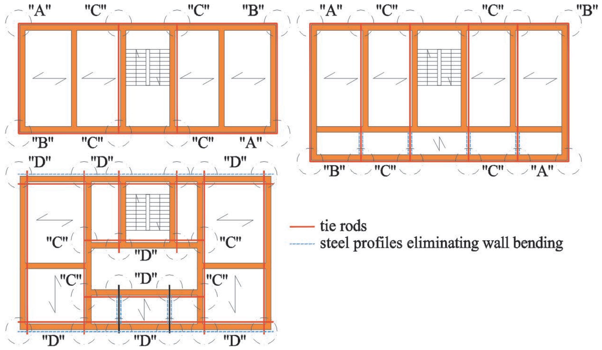
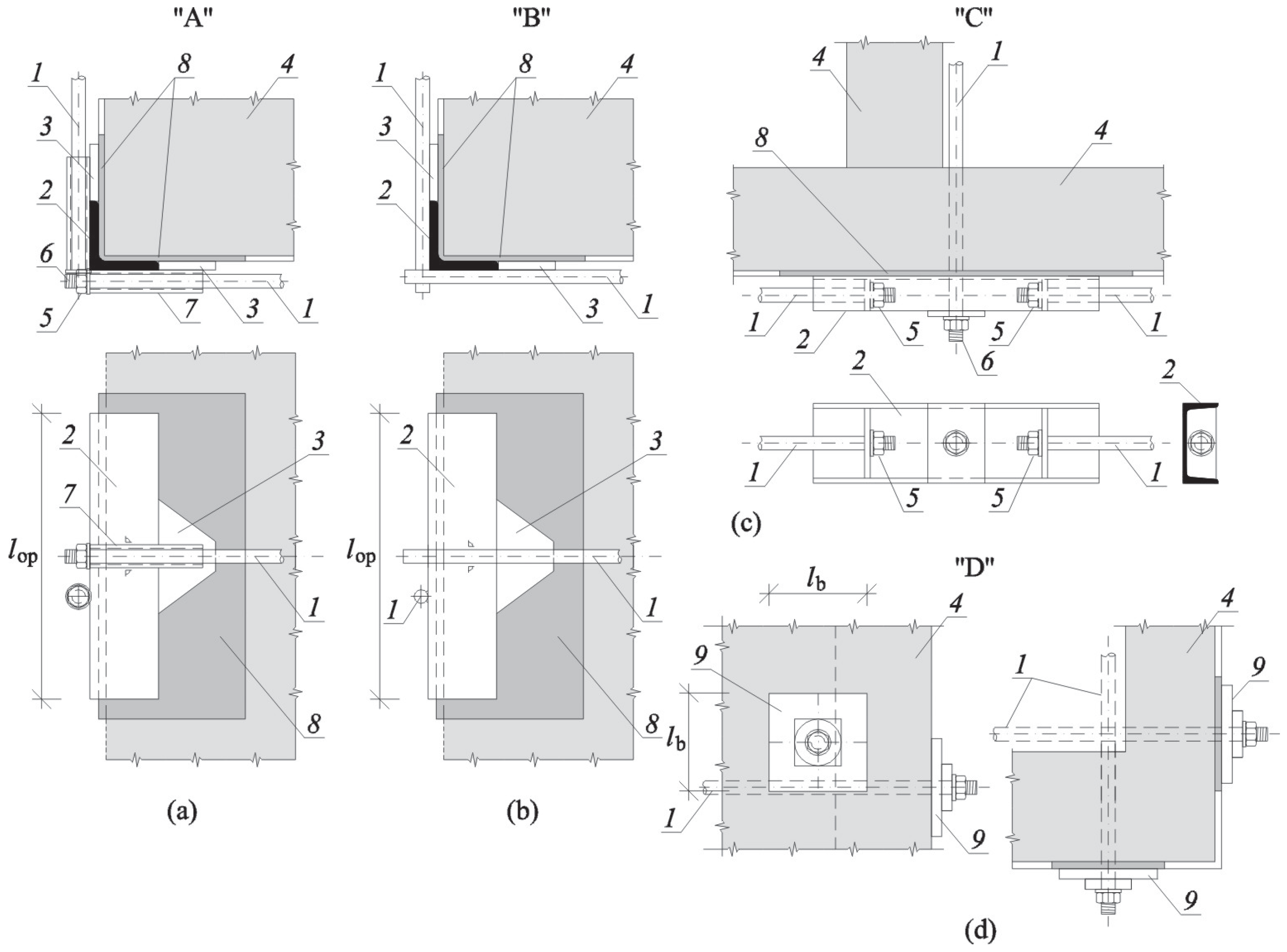
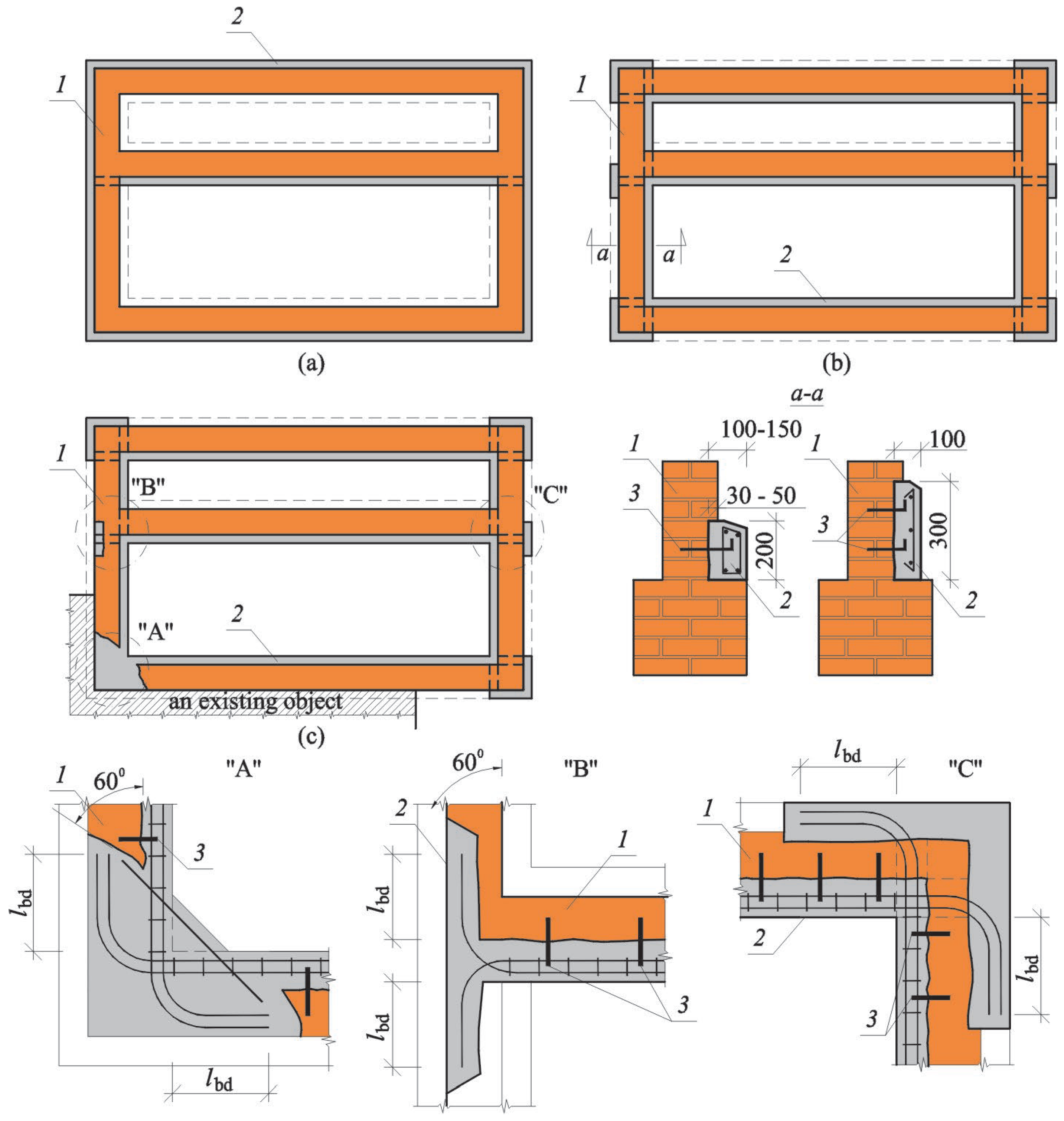
2.1.2. Examples of the Strengthening of Ground Parts of Buildings

Tie rods are placed along load-bearing or shear walls, close to the bottom surface of the floor (or between wood beams) and anchored into external surfaces of walls. The transfer of forces from tie rods is beneficial when this mechanism occurs through rolled profiles placed along the whole length of walls, restraining the impact of tie rods on the top edge of the wall, which leads to its bending. The issue of the settlement of tie rods in chases, whose breaking out is very time consuming, is disputable. The principle can be applied that the momentary settlement of tie rods is necessary if the construction work cause damage to and removal of tie rods, as the immediate protection can be dangerous. If the non-uniform settlement does not cause serious damage, then tie rods can be eliminated or, after consultation with the building owner, left as the permanent protection. Examples of calculated strengthening are presented in paper [36], an example arrangement of tie rods in buildings having various shapes is illustrated in Figure 2, details of the anchorage of tie rods are shown in Figure 3, and a view of buildings strengthened with tie rods is shown in Figure 4.

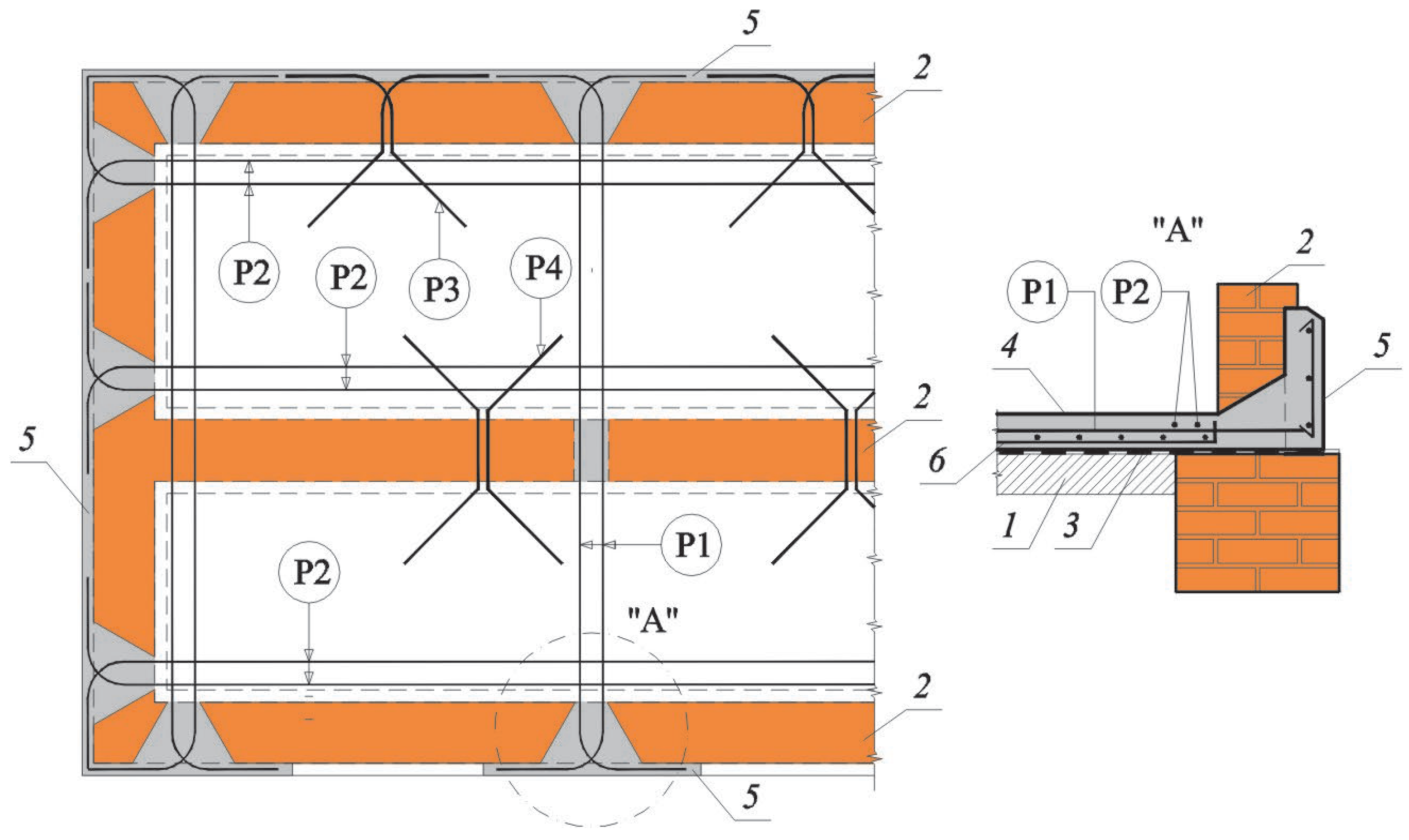
2.2. Protection of Underground Parts of Buildings

During the process of performing a deep excavation, the building is simultaneously subjected to horizontal deformations (ε) and the radius of the ground curvature (R). When restraints are calculated, each of these effects is analysed individually assuming that internal forces caused by horizontal deformations of the ground ε are completely absorbed by the foundations or the underground part of the building [37,38].

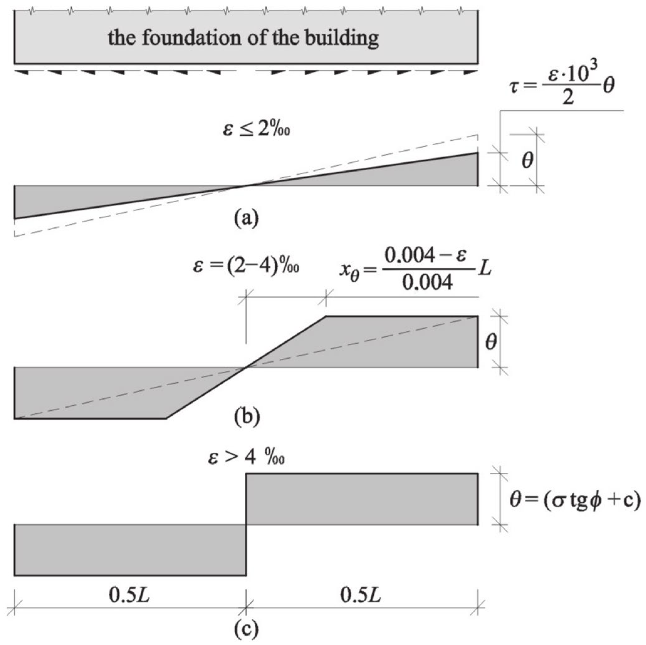
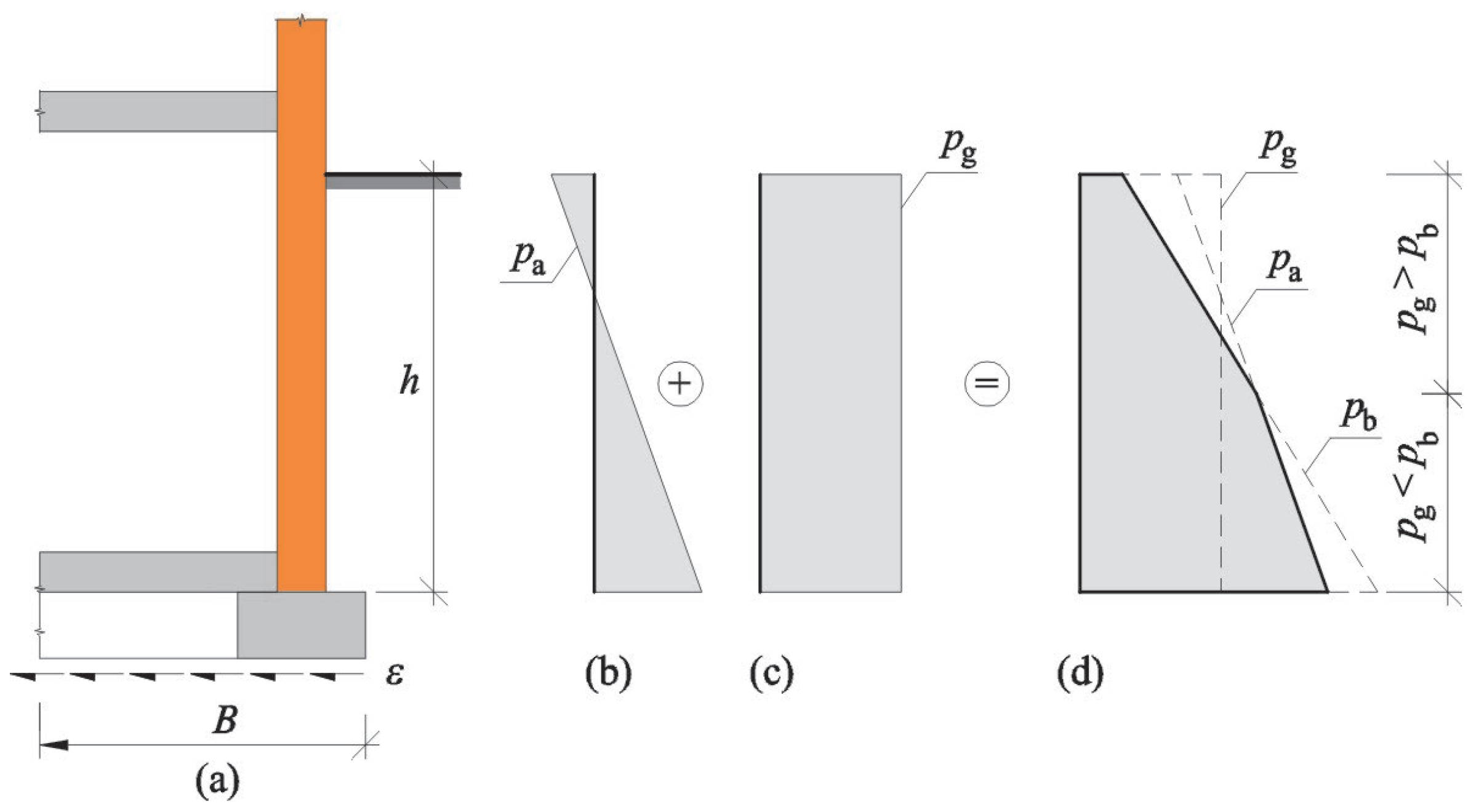
2.2.1. Determining Internal Forces in Foundations

Maximum tension forces in the foundations are observed at a hogging basin, that is, in the phase after performing the deep excavation and erecting a new building. Forces can be calculated on the basis of general rules specified in the instructions [39]; however, it is recommended to take the modified distribution of shear stresses τ in the foundation base [29] according to Figure 5. This modification included the variation of stress distribution which depends on values of horizontal deformations of the ground ε, which is particularly important at their low intensity.
The instructions [34] do not specify the method used to determine horizontal deformations of the ground, which cause serious stresses even at relatively small values. If horizontal displacements of the ground are known, then horizontal deformations can be determined. Assuming that horizontal displacements of the ground change linearly as in case of vertical displacements, and take the maximum value uk = max uk at the excavation shoring, at the end of the zone of direct impacts (SI) they are equal to uk = 0.5 max uk, and at the end of the zone S they are uk = 0. Hence, a function can be specified that describes horizontal displacements of the ground depending on the distance x from the excavation shoring expressed as:
u I x = max u k 0.5 max u k S I x   for   0   x     S I ,
u I I x = 0.5 max u k S S I S x   for   S I < x S .
Horizontal displacements are calculated as a derivative of the function of horizontal displacements. The following relationships are obtained for individual ranges:
ε I = d d x u I x = 0.5 max u k S I   for   0   x     S I ,
ε I I = d d x u I I x = 0.5 max u k S S I   for   S I < x S .
Deformations that lead to tension in foundations change their character at a point within a distance SI from the excavation shoring, and they are calculated from the following relationship:
ε = ± 0.5 max u k 2 S I 0.5 max u k 2 S S I .
Excluding emergencies, displacements during the works on deep excavations do not exceed 50 mm. Therefore, horizontal displacements of the ground causing tension in the foundations are equal to ε = 2 ‰, and the distribution of shear stresses can be taken in accordance with Figure 5a. The maximum longitudinal force in the foundation can be expressed as:
F ε f = 1 4 τ L b = ε 10 3 8 σ t g ϕ + c L b ,
where σ is the normal stress at the foundation level, ϕ is an angle of internal friction, c is cohesion, l is the length of foundation, and b is the width of foundation.
In addition to forces acting in the plane of foundations, forces acting on their side surfaces should also be considered in accordance with principles specified in the instructions [16]. Depending on the size proportions of a part of the foundation set below the grade, such forces are equal to:
F ε fb = 0.75 h b F ε f   for   h / b     1 / 3 , F ε fb = h b D θ F ε f   for   h / b   >   1 / 3 ,
D = γ h s t g ϕ t g 2 π 2 ϕ 2 + c 1 2 t g ϕ t g π 2 ϕ 2 ,
where γ–is weight density of soil and hs is distance between the mid-height of the foundation and the surface area.
At the sagging basin, the density of soil increases which generates the additional pressure pg put on parts of outer walls set below the grade. The general scheme of wall loading is shown in Figure 6: active earth pressure pa—this diagram sum with the additional pressure pg. The total soil pressure on the basement wall p cannot be greater than the passive pressure pb.

2.2.2. Examples of the Strengthening of Underground Parts of Buildings

There are many brick buildings in high-density housing which were generally built until the post-war period, and they are often in poor condition. Underground parts of such buildings are not completely adapted to resist forces generated by horizontal deformations of the ground. To avoid or restrain damage to these buildings, their underground parts require strengthening.
Depending on the effects caused by horizontal displacement of the ground, the following types of protection are applied:
For tensile deformations: reinforced concrete aprons, anchored diaphragms;
For compressive deformations: anchored diaphragms, treatments that restrain ground pressure on foundations.
The most common method used to strengthen buildings against horizontal movements of the ground is the application of reinforced concrete aprons (tie rods) within the area of foundation walls or at the level of foundations. The aprons are placed on the external circumference of the building and if required, along internal walls (Figure 7). The circumferential reinforced concrete aprons placed on the external surface of the wall are the most effective (Figure 7a). However, soil around the building has to be uncovered down to the level of the foundations. In case of buildings with strongly corroded and weakened basement walls, this can lead to structural instability. Therefore, before the decision on placing aprons along the external circumference is made, technical conditions of basement walls and the type of soil should be thoroughly analysed. In some cases, it can be reasonable to perform aprons that will run through internal surfaces of the external walls (Figure 7b). Then, uncovering of the building is required only at places of anchoring these aprons. The aprons can be also required on the internal sides of walls at the movement joints and walls adhered to the adjacent building (Figure 7c).
To improve interactions between reinforced concrete aprons and basement walls or foundations, the wall should be broken up at the height of the apron to a depth no smaller than 3 ÷ 5 cm, and steel hooks on ribbed bars should be installed. It is best to install reinforced concrete aprons at the level of the basement floor. Then, a type of shield is developed that stiffens the building. The usual cross-section of the apron is 100 − 150 ÷ 200 mm, but its height cans be increased even up to 300 mm if the building’s resistance to the ground curvature has to be improved. Then, bending stiffness of the wall also increases.
The aprons should be constructed as reinforced concrete elements, paying particular attention to maintain the required embedded length of rebars (lbd), and the required length of laps (ls) at connecting rebars. In case of no access to the wall front (footing), the aprons can be anchored by dovetailing—detail ”A” in Figure 7. For very serious damage to the foundation walls (Figure 8a), the aprons can be placed on both sides of the strengthened wall.
In addition to aprons adjusted to resist tensile forces, anchored diaphragms can also be employed. They can also resist compressive forces and ensure geometrical invariability of the horizontal plan of the building. The diaphragms are constructed (Figure 9) as a reinforced concrete slab placed on one level, with a thickness of ca. 10 cm, with two-way reinforcement. The diaphragm is placed on the existing floor at the lowest level (in buildings with the basement, on its floor) through the sliding layer. The diaphragm should be fitted as a continuous structural element connected with the walls, mainly with circumferential walls. In addition to the orthogonal reinforcement, the diaphragm should also have concealed tie rods running along external circumferential walls of a building (a block) and internal load-bearing walls (P2). Additional concealed intermediate tie rods (P1) are placed when required due to static calculations or difficulties with effective anchorage of tie rods running along the walls. Depending on the arrangement of internal walls in the building and the results from static calculations, the distance between tie rods should range from 3 to 6 m
Each tie rod has to be anchored in circumferential walls to resist the force obtained from calculations. The simplest method to anchor tie rods is to break out pockets in the wall in a dovetailing shape and set in concrete rebars ended with loops and hooks. If anchorage through dovetailing does not provide the transfer of required forces, then the rebars should be anchored on external sides of the wall, e.g., in reinforced concrete aprons. When additional strengthening of the external wall footing is necessary against horizontal forces, then additional anchor rods P3 and P4 which are installed inside the diaphragm slab and outside the reinforced concrete apron can be used.
The general rules for calculating and constructing anchored diaphragms in existing buildings are the same as in designed buildings. However, due to some difficulties and high costs, diaphragms are installed in existing buildings in exceptional cases. This type of strengthening is regarded as reasonable when horizontal displacements of the ground are significant and equal to ε = 12 ÷ 15 ‰ [30].

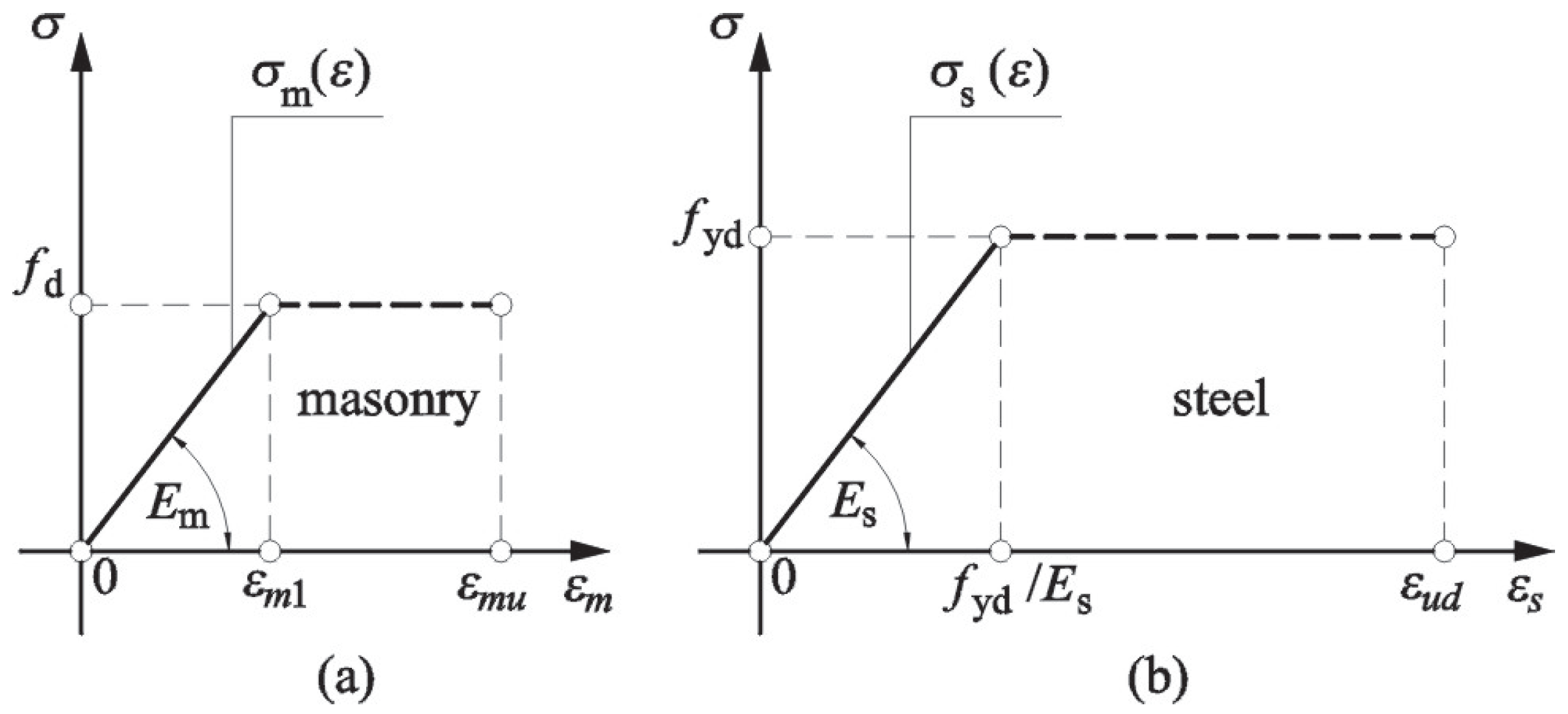
3. Original Proposals to Verify ULS for Masonry Buildings

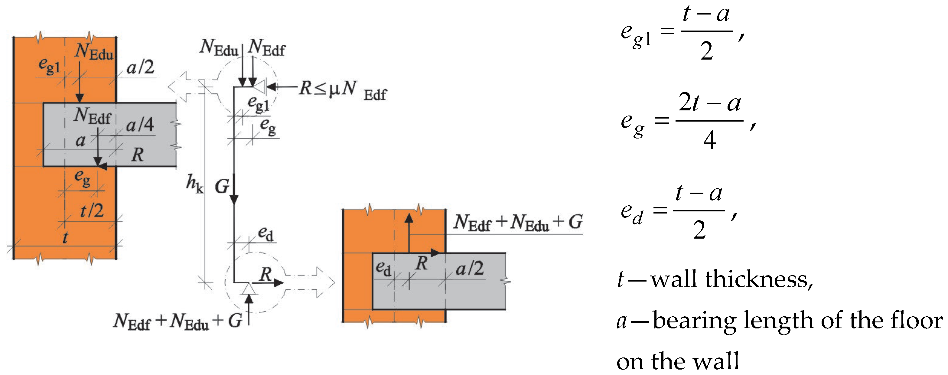
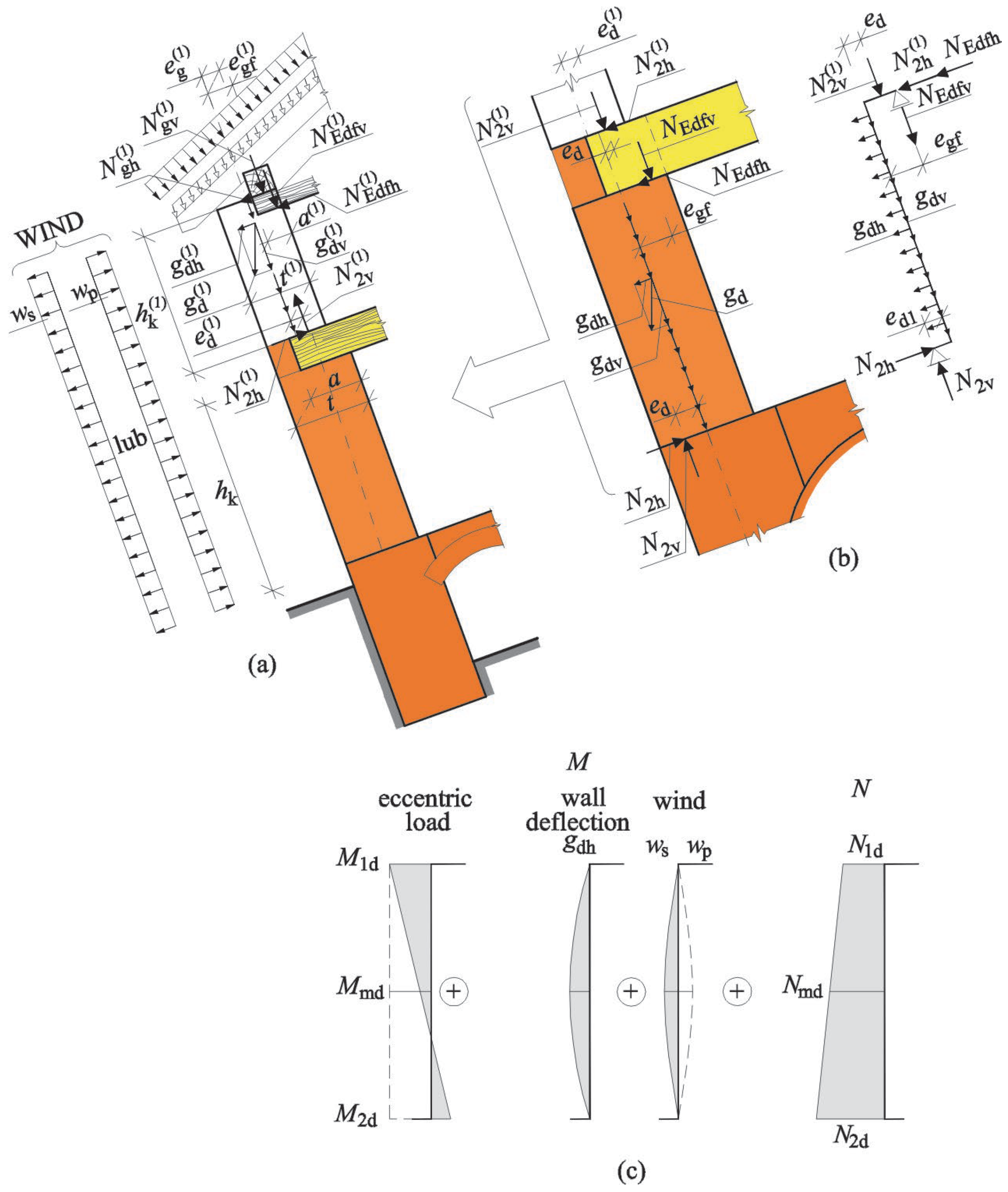
3.1. Detailed Method for Calculating the Strengthening of Walls–Original Proposal

This detailed method used to calculate the strengthening required for the ground part of the building subjected to non-uniform settlement assumes that steel tie rods resist resultant tension forces and the wall resists the resultant compressive force. If the non-uniform settlement of the building part is lower than the limit value, taking into account the serviceability limit state [sk]u, no cracking is observed in the building which means that the building settles in the elastic state. Assumptions of possible formation of cracks taken in calculations are parallel to conventional computational methods for such structures [38] and are definitely simpler in application when compared to linear and elastic solutions for multi-layered systems described in many papers, e.g., papers [40,41,42]. Cracks develop after exceeding limit values of non-uniform settlement, and the angle of building deflection after cracking is determined using the equation:
T 1 = max s k s k u L 0 .
Due to deflection of the building, pressure implied on the ground changes from the rectangular characteristic for the pre-deflection state to the trapezoid, in which the greatest values of load are found in the place of the greatest displacement of the building. The resultant ground reaction is balanced by the resultant pressure exerted on the ground. Assuming the linear path of ground settlement, the ground reaction will be also linear, and due to this settlement, the reaction is minimal at the most displaced edge. The superposition of pressure and ground reaction results in the linearly variable path of resultant loads acting on a fragment of the building. Stress values at opposite edges have to be the same and they are equal to σ 3 :
σ 3 = σ 1 σ 2 = 12 M L 0 2 t z = 6 Q x x H o L 0 2 t z ,
where tz is total wall thickness.
The resultant force acting on the bottom edge of the building is:
P = 1 2 σ 3 t z L 0 = 3 Q x x H o L 0 .
The component of horizontal force Qxx of the total weight of the building Q depends on the increment in the angle of building deflection and is equal to:
Q x x = Q sin T 1 = Q max s k s k u L 0 .
The bending moment causing rotation of a part of the building is:
M o = 2 3 P L 0 + W H 0 2 bending   moment due   to   wind   action = 2 Q max s k s k u H 0 L 0 + W H 0 2 .
Equation (23) includes the additional bending moment caused by the action of the resultant force of the wind W.
To restrain potential damage, it is assumed that the wall in the compressed zone and tension steel of tie rods react in the linear and elastic range, and consequently plastic properties of both materials are neglected—Figure 10a,b.
Additionally, tie rods can be considered to be initially prestressed and able to resist the force ΔF. The analysed material models of the wall and steel, and the system of forces acting on a fragment of the building are shown in Figure 11.
To determine internal forces in tie rods and compressed parts of the wall, conditions of balancing horizontal forces and bending moments are analysed in relation to the neutral axis of the section. The static equations are expressed as:
F x = 0 Q x x W 1 2 σ m t x e f f + i = 1 n σ s i A s i + Δ F i = 0 ,
M = 0 M o + 1 2 σ m t x e f f 2 3 x e f f + i = 1 n σ s i A s i + Δ F i h i = 0 ,
where σ m represent normal stresses in outer fibres of the wall (parallel to the plane of bed joints), σ s i is normal stress in steel, and Δ F i represents initial jacking forces in tie rods.
Geometrical conditions for deformations in the section can be expressed as:
ε m x e f f = ε s 1 h 1 ,   ε m x e f f = ε s 2 h 2 ,   ε m x e f f = ε s n h n ,
where ε m represents deformations of outer fibres of the wall (parallel to the plane of bed joints and ε s 1 , ε s 2 , ε s n ĺs are deformations of steel.
The connection between stresses and deformations is described by the following relationships:
σ m = ε m E m ,   σ s 1 = ε s 1 E s ,   σ s 2 = ε s 2 E s ,   σ s n = ε s n E s ,
where Em is the modulus of elasticity in a direction parallel to the plane of bed joints and Es is the modulus of steel elasticity.
Taking into account the relationships (26) and (27) and assuming that the area of tie rods at each level is the same and equal to As (the sum of cross-section area of tie rods is equal to Fa), the system of equations is obtained, in which deformations in the compressed zone of the wall ε m and a height of the compressed zone of section x e f f are unknown:
Q x x W 1 2 ε m E m t z x e f f + ε m A s x e f f i = 1 n h i + i = 1 n Δ F i = 0 M 0 + 1 3 ε m E m t z x x e f f 2 + ε m A s x e f f i = 1 n h i 2 + i = 1 n Δ F i h i = 0 ,
where:
  • Qxx—component of horizontal force acc. to (22);
  • W—the resultant force caused by wind action (acc. to Figure 11);
  • As—the area of reinforcement at a given level hi;
  • hi—distance between reinforcement and the neutral axis of wall section;
  • Δ F i —jacking forces in tie rods;
  • M0—bending moment causing rotation of a part of the building acc. to (23).
To avoid potential damage in the lowest parts of the wall, the height of the compressed zone of the wall section should not be smaller than the height of the floor xeffhp.
When deformations of the wall are known, compressive stresses can be easily calculated, and their value should not exceed the design compressive strength of the wall fd in a direction parallel to the plane of bed joints:
σ m = ε m E m f d .
Stresses at individual levels can be determined similarly from the following relationships:
σ s 1 = σ m h 1 x e f f E s E m ,   σ s 2 = σ m h 2 x e f f E s E m ,   σ s n = σ m h n x e f f E s E m .
The material parameters of the wall Em and fd should be determined with in situ tests during diagnostics tests conducted on the structure, using analysed fragments of the walls, or from tests performed on component elements of mortar and masonry units. Literature data on historic buildings can be also helpful. Extensive information on compressive strength of the wall is presented in paper [11].
If the strengthening plan does not include initial tensioning of tie rods, after their installation, the tie rods should be prestressed so that no clearance is detectable. If tensioning is necessary, then a relevant force should be applied using a torque wrench. When tie rods are outside the building, then changes in pulling tension in tie rods that are caused by diversified properties of the wall and steel should be included. Additional forces generated by a difference in temperature are determined from the following equation:
F t = α t s α t m Δ t E A s ,
where αts and αtm are coefficients of thermal expansions of steel and the wall, Δt is a difference in temperature, E is the modulus of steel elasticity, and Ft represents the cross-section area of the tie rod.
The difference in temperature in Equation (31) is specified with reference to the temperature of installing tie rods. In practice, the descending of tie rods leads to a beneficial increase in compressive stresses, and then the control over tension is not required. However, heating tie rods is a dangerous situation. An increase in the temperature of tie rods by Δt = +20 °C necessitates controlling their tension. For temporary strengthening of buildings, it is rational to place tie rods inside the building, where temperature variations are subtle, and the control of stress using bottle screws is not troublesome. When tie rods are placed outside the building, both the installation and the control of stress, particularly at higher levels, are troublesome, and thus often neglected.

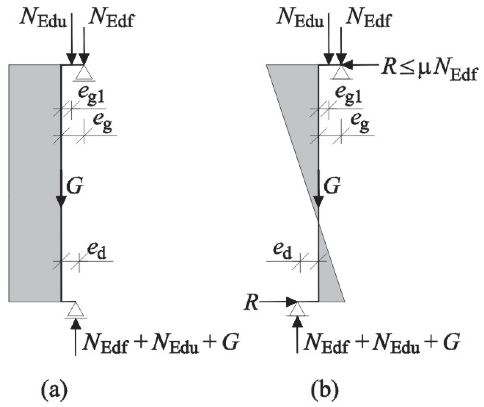
3.2. Adaptation of the Method for Verifying ULS of Walls Subjected to Vertical Loading

During the whole period of performing deep excavation and after completing the project and the occurrence of permanent deflections, ultimate limit states should be met for walls subjected to vertical loading. Deflection of a building generates components of horizontal loads in walls and forces acting from the floors. The simplified frame model can be used for the model of a building wall primarily under vertical load—Figure 12a, according to PN-EN 1996-1-1 [31]. The lack of possibility of including components of vertical load caused by deflection is a serious drawback of this solution—Figure 12b. This problem can be solved using information presented in point 5.5.1 of the standard [31]: “(2) The bending moments may be calculated from the material properties given in Section 3, the joint behaviour, and from the principles of structural mechanics. NOTE A simplified method for calculating the bending moments in walls due to vertical loading is given in Annex C. Annex C(4) and C(5) may be used with any calculation, including linear elastic theory”.
According to the above sentences, values of internal forces in representative sections of a wall can be determined using a bar/frame model of the building. Each vertical load applied to the computational model of the wall should be distributed onto a component that is perpendicular and parallel to the surface of the inclined ground. Hence, in addition to bending moments and axial loads calculated as for the vertical model (Figure 12c), additional values of internal forces of horizontal components (Figure 12d) are obtained.
The combination of loads should take into account the variable deflection of the building that is caused by various curvatures of the ground basin, and values of internal forces generating the most unfavourable conditions should be used in calculations to verify ULS. It is more troublesome to verify the load-bearing capacity of deflected masonry walls with possible cracks in floors or timber woods, which suggests the use of the hinged model. Information in Annex C to the standard, which specifies the simplified method for determining internal forces in the vertical wall, is not sufficient for verifying ULS. Generally, the wall model is represented by a bar, the top end of which is subjected to longitudinal forces acting from higher levels NEdu at the eccentricity eg1, and the force acting from the level NEdf at the eccentricity eg.
The resultant vertical force at the eccentricity ed is acting on the bottom end of the bar. For arbitrarily imposed eccentricities of vertical forces in the top and bottom edges of the wall, it is easy to demonstrate that the equilibrium states are not met. Therefore, a couple of horizontal forces R are required in the junction between the walls and the floors to ensure the equilibrium state of the bar. In a real structure, horizontal forces in the top and bottom ends of a wall are a result of friction (cohesion is neglected) between the beams and the wall, which depends on the load from the floor. The maximum value can reach RμNEdf (μ–coefficient of friction between wood beams and the wall), Figure 13.
This simplified standard model based on, inter alia, transferring loads from higher levels in the middle bearing length of the floor can be used to verify the load-bearing capacity of any wall while ignoring the eccentricity of load transfer from the walls placed above. This assumption can be considered as true if the floors are continuously supported (tie rods) on the wall at a bearing length a. For timber floors with a relatively large spacing of beams and no ring beams, the assumption that load is transferred in the middle of the bearing length of the floor is a risky simplification that underestimates values of bending moment in the wall. It is correct to assume that the top edge of the analysed wall is subjected to loads imposed from walls at higher levels, not in the middle of the bearing length of the floor on the wall, but at a certain eccentricity resulting from the equilibrium states of the wall. In the first case, no horizontal forces are assumed to occur at a junction of the floor. Then, the analysis can be conducted for a model of the rebar, whose top end is subjected to vertical load from higher levels, and to vertical force from the floor, and the bottom end is subjected to vertical load at unknown eccentricity ed, Figure 14a. The model is in the equilibrium state only due to vertical forces (R = 0); hence, the eccentricity of the force in the bottom edge of the wall is equal to
e d = N E d u e g 1 + N E d f e g N E d u + N E d f + G ,   e d 0.45 t .
In the second case, the floors can be assumed to be a horizontal support of the wall, and horizontal forces R act on the top and bottom end of the wall. This solution is reached when the wall is regarded as the bar supported at the base of the eccentricity (quasi-restraint) and is supported with the roller supports at the top (statistically indeterminate), Figure 14b. Then, the value of horizontal force R is calculated from the following equation:
R = 3 2 N E d u e g 1 + N E d f e g h k μ N E d f ,   e g 1 0.45 t .
At maximum eccentricities of forces acting on the top edge of the wall of 0.45t and the average ratio of the floor height to the wall thickness hk/t = 10, the horizontal force at the junction between the wall and the floor does not exceed 5–8% of the total load imposed on the wall. Eccentricity at the bottom edge of the wall is calculated from the following relationship:
e d N E d u + N E d f + G + N E d u e g 1 + N E d f e g R h k = 0 , e d = 1 2 N E d u e g 1 + N E d f e g N E d u + N E d f + G ,   e d 0 , 45 t .
In both cases, the eccentricity eg1 of loads from higher levels NEdu at the top edge of the wall is determined with analysis of each wall at a higher position and determining the eccentricity. Ignoring or including horizontal forces at the junction results in a clearly diversified arrangement of bending moments in the wall. Taking into account the ULS specified in the standard [31], according to which the absolute value of bending moments in the end sections and at a mid-height of the wall is significant, the most unfavourable is the model ignoring forces at a junction between the floor and the wall, with a bending moment caused by vertical loads that is constant along the whole height of the bar. If forces at the junction are ignored, then horizontal loads imposed by wind or wall deflection cannot be taken into account. The model that includes forces at the junction is characterized by greater load-bearing capacity, but this junction should be rigid, and junctions are often considerably loose due to the effect of biological corrosion of wood or damage to the wall.
The model with horizontal forces at a junction between the floor and the walls can be used for a deflected building. In this case, vertical forces from higher levels and the self-weight of the wall are accompanied by horizontal forces that change the values of bending moments in the wall.
Due to the asymmetry of impacts, and the required determination of eccentricities of vertical loads from walls at higher levels, the outer wall in a two-storey building with a basement, which is deflected at an angle T, shown in Figure 15, is the best illustration of calculations for a deflected wall.
The height and thickness of the wall at the highest level are h k 1 , t 1 , respectively. The bearing length of the timber floor at the highest level is a 1 . The wall at the analysed level has a height and a thickness equal to hk, t. Vertical loads transferred to walls from the roof and the floor at the highest level are resolved into components that are parallel and perpendicular to the longitudinal axis of the wall with the general relationships:
N g h 1 = N g 1 sin T ,   N g v 1 = N g 1 cos T , N E d f h 1 = N E d f 1 sin T ,   N E d f v 1 = N E d f 1 cos T ,
where N g 1 is the vertical load imposed by the roof on the wall, kN, N E d f 1 is the vertical load imposed by the attic floor on the wall, N g h 1 , N g v 1 are perpendicular and parallel components of the vertical load from the roof, and N E d f h 1 , N E d f v 1 are perpendicular and parallel components of the vertical load from the attic floor.
Loads from the roof and the attic floor are imposed at eccentricities equal to e g 1 , e g f 1 . Consequently, the wall weight is resolved into components that are parallel and perpendicular to the wall axis:
g d h 1 = g d 1 sin T ,   g d v 1 = g d 1 cos T ,
where g d 1 is weight of a wall (kN/m), and g d h 1 , g d v 1 are perpendicular and parallel components of the wall weight (kN/m).
The condition for a sum of floor plans is used to determine vertical and horizontal forces transferred to a lower level:
N 2 v 1 = N g v   1 + N E d f v   1 + g dv 1 h k 1 ,   N 2 h 1 = N g h   1 + N E d f h   1 + g dh 1 h k 1 .
And the conditions for force equilibrium against the wall base are used to determine the eccentricity of vertical force from the following relationship:
e d 1 = 1 2 N g v   1 e g 1 + N E d f v   1 e g f 1 N g v   1 + N E d f v   1 + g dv 1 h k 1 N g h   1 h k 1 + N E d f h   1 h k 1 N g v   1 + N E d f v   1 + g dv 1 h k 1 .
The horizontal component of the self-weight of the wall can be ignored as it only generates a wall bending in the plane. As the hinge support was taken for wall ends on the supports, there are only horizontal components that provide equilibrium. The resultant at the bottom edge should be within the wall section, which means that the condition e d 1 0 , 45 t 1 should be satisfied otherwise the structural instability of the wall can be observed. For various values of wall thickness, the eccentricity should be transformed against the axis of the analysed wall based on the following relationship:
e d = t 1 2 t 2 + e d 1 .
The same procedure should be applied to the wall at the analysed level. At first, loads from the floor and the wall weight are resolved into components that are perpendicular and parallel to the wall axis (acting at an eccentricity of egf):
N E d f h = N E d f sin T ,   N E d f v = N E d f cos T ,
where NEdf is the vertical load imposed by the floor on the wall, and NEdfh and NEdfv are perpendicular and parallel components of the vertical load from the floor.
The wall weight is resolved into components that are parallel and perpendicular to the wall axis:
g d h = g d sin T ,   g d v = g d cos T ,
where gd is weight of the wall (kN/m), and gdh and gdv are perpendicular and parallel components of the wall weight (kN/m).
The condition for a sum of floor plans is used to determine vertical and horizontal forces in the top and bottom sections of the wall:
Top edge of the wall
N 1 v = N 1 d = N 2 v   1 + N E d f v   , N 1 h = N 2 h   1 + N E d f h   ;
Bottom edge of the wall
N 2 v = N 2 d = N 1 v   + g d v h k , N 2 h = N 2 h   + g d h h k .
Bending moments in the top and bottom edges of the wall are as follows:
Top edge of the wall
M 1 d = N 2 v   1 e d + N E d f v   e g f ;
Bottom edge of the wall
M 2 d = 1 2 M 1 d   N 2 h 1 + N E d f h h k .
At the mid-height of the wall, axial forces can be calculated as the mean arithmetic value of forces in the ends of the wall, and the bending moment should be increased by the effect of the in-plane bending of the wall caused by the horizontal component of the self-weight and the effect of wind using the following relationships:
N m d = 0.5 N 1 d + N 2 d .
M m d = 1 2 M 1 d   + M 2 d eccentric   and   horizontal   load + g dh h k 2 8 deflection ± w s h k 2 8   or   w p h k 2 8 wind .
The load-bearing capacity of the wall mainly subjected to vertical load is verified in the top and bottom sections and at its mid-height. Reduction factors for load-bearing capacity in sections above and below the floor [31] should be determined with the following relationships:
ϕ 1 = 1 2 e 1 t = 1 2 M 1 d / N 1 d + e i n i t t ,
ϕ 2 = 1 2 e 2 t = 1 2 M 2 d / N 2 d + e i n i t t ,
where hinit = hef/450 − initial eccentricity according to point 5.1 of the standard [31].
At the mid-height of the wall, the reduction factor for load-bearing capacity ϕ m is a function of the eccentricity of vertical load em, which can be determined according to Annex G to the standard [31].

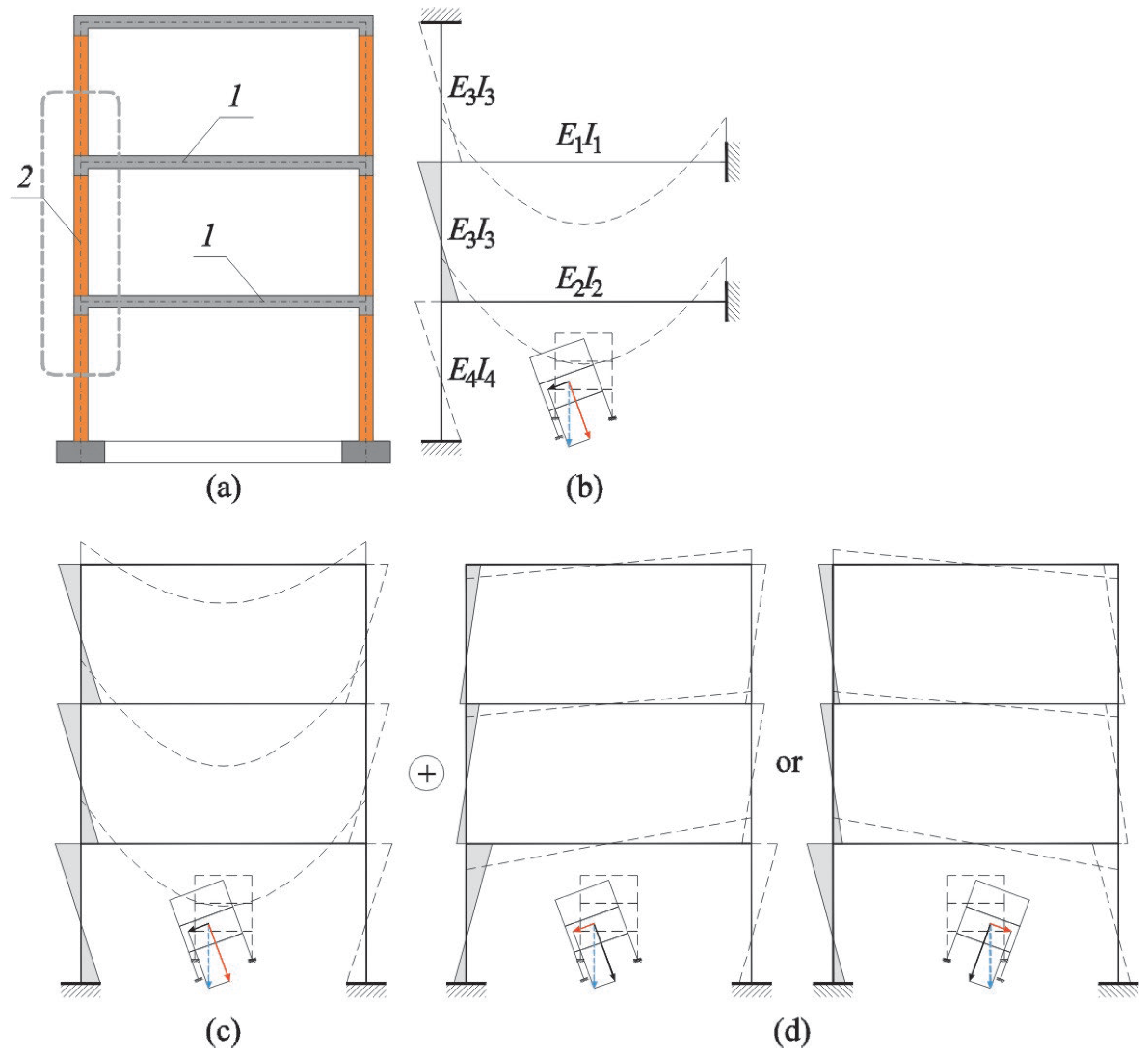
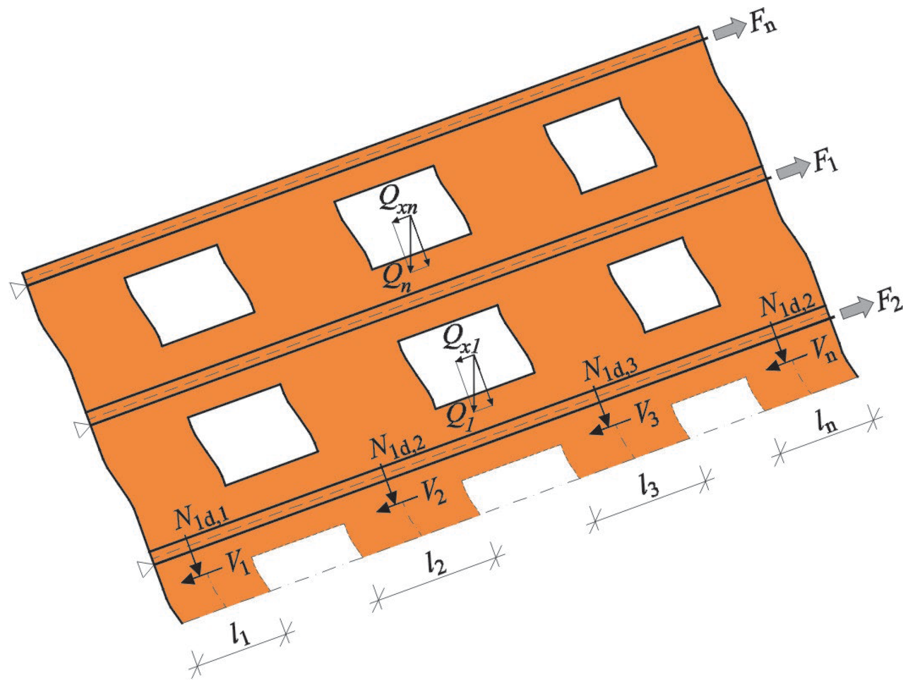
3.3. Adaptation of the Method for Verifying the Shear ULS of Pillars between Openings

The horizontal components generated during the deflection of the building are transferred to load-bearing walls and cause their in-plane bending. The horizontal component in stiffening walls causes shearing that develops inclined cracking. Pillars between windows are the most vulnerable elements in the building structure, Figure 16.
The cumulative horizontal force generated by the deflection of the building and the presence of tie rods in the floor at the analysed level should be distributed proportionally to stiffness of the pillars according to the following relationship:
V n = Q x F J n J n ,
where Vn is the horizontal shearing force acting on the analysed pillar, Jn is the moment of inertia of the analysed pillar, Q x is the sum of components of force parallel to the ground surface above the analysed stiffening wall, F is the sum of force in the tie rods, which is above the analysed stiffening wall, and J n is the sum of inertia moments of the cross-sectional area of pillars between windows.
Shear resistance of the individual pillar should be verified in accordance with point 6.2 of Eurocode 6 [31] from the general relationship:
V E d V R d ,
V R d = f v d t l c = f v k 0 + 0.4 σ d γ M t l c = f v k 0 + 0.4 N / t l c σ d γ M t l c ,
where VEd = Vn is the design load acting on the pillar, V Rd = f vd t l c is the calculated shear resistance of the pillar, lc is the length of the compressed zone of the pillar. If precise calculations are not performed, then lc = ln can be taken (cf. Figure 16). fvd is the design shear resistance of the wall at mean vertical stresses calculated for forces N, fvk0 is the initial shear resistance of the wall, determined in accordance with point 2.4.1 and point 3.6.2 of Eurocode [31], and t is the thickness of the pillar.

4. Results

The non-uniform settlement of the building induced by deep excavation creates additional actions (forces) in the elements and additional deformations and displacement, which deteriorates ultimate limit states (ULS) and serviceability limit states (SLS). As a matter of ULS and SLS, limit values of non-uniform settlements are determined with national know-how related to deep excavations or mining impacts. In Poland, the impacts of deep excavations are evaluated on the basis of know-how in the field of mining impacts and the current, not so extensive know-how about deep excavations. The safety of buildings in the impact zones of deep excavations is provided using two basic methods for protecting buildings, which consist in strengthening the structures against deformations related to ground displacements and reducing non-uniform settlements of buildings. While constructing deep excavations, buildings are simultaneously exposed to horizontal deformations (ε) and curvature (R), which are then completely taken by the foundations or the underground part of the building. Protection of a building against non-uniform displacements refers to the ground and underground parts of the building.
In the underground parts of a building, maximum tension forces in the foundations are observed at a hogging basin, that is, in the phase after constructing a deep excavation and erecting a new building. Forces can be calculated on the basis of general rules specified in the instructions [39]; however, it is recommended to consider the modified distribution of shear stresses τ in the foundation base [29] (cf. Figure 16). This modification includes a change in the stress distribution according to values of horizontal deformations of the ground ε, which is particularly important at their low intensity. Depending on the effects of horizontal displacement of the ground, the following is applied for tensile strengths: circumferential aprons, anchored diaphragms; and for compressive strains: anchored diaphragms and other treatments reducing ground stress on the foundations. The most common method used to strengthen buildings against horizontal movements of the ground is the application of reinforced concrete aprons (tie rods) within the area of foundation walls or at the level of foundations. The aprons are placed on the external circumference of a building and if required, along internal walls. The most effective reinforced concrete aprons are placed on the outer surface of the wall. Aprons running through the internal surface of external walls seem to be reasonable in some cases. Then, uncovering the building is required only at places of anchoring these aprons. The aprons can also be applied on the internal sides of walls at the movement joints and on walls adhered to the adjacent building. In addition to aprons adjusted to resist tensile forces, anchored diaphragms can also be employed. The general rules for calculating and constructing anchored diaphragms in existing buildings are the same as those in designed buildings. Due to some difficulties and high costs, sheaths are installed in existing buildings in exceptional cases.
The ground parts of a building are strengthened with steel tie rods, which can absorb horizontal forces produced by interactions between the building and the ground. In Poland, ULS and SLS for buildings near deep excavations are verified according to the instructions [34], the standard PN-B-03002:2007 [35], and Eurocode 6 [31]. Instructions [18] can be used to determine the total area of steel tie rods Fa depending on the maximum difference in the foundation settlement (max sk − [sk]u). Unfortunately, there is no information on the method of placing reinforcement at the building height and on the value of initial jacking force. Forces in tie rods can be changed during the construction of deep excavations, which affects the stress state of masonry walls. These parameters cannot be verified according to instructions [34]. This standard [35] can be used to determine the limit values of shear strains of walls which determine the serviceability limit state SLS. Eurocode 6 [31], considered as the basic standard for designing masonry structures, does not specify any methods for verifying ULS for inclined masonry walls and ULS for shear masonry pillars as a result of deflection or initial tensioning of steel tie rods. This paper presents original procedural algorithms, which include assumptions from the instructions [34] and the standard Eurocode 6 [31]. In case of inclined walls, the developed algorithm includes an increase in eccentricities of actions caused by deflection and the presence of horizontal components of loads. The proposed algorithm for verifying shear resistance offers individual analysis of each pillar after separating horizontal loads proportionally to stiffness. Each pillar can be analysed individually, taking into account the length of the compressed zone of the wall.

5. Conclusions

Parties of the construction process should be aware that all objects located in the direct vicinity of the excavation will require additional strengthening during the construction work. There are treatments for reducing displacement (non-uniform settlement) and strengthening the ground and underground parts of a building.
Conventional solutions, such as steel tie rods or scattered ring beams are applicable for the ground parts of a building. Calculations for these elements can be made with the simplified method without monitoring values of forces in rods and stresses in the compressed zones of the walls. These clear deficiencies were eliminated with the introduction of the detailed method for calculating such strengthening, which can:
Determine the area of steel tie rods in any location along the building height;
Determine the additional prestressing forces in the rods depending on the process of building settlement;
Determine values of compressive stresses in the compressed zones of the building section.
The proposed method is based on standard assumptions and can compete with commonly applied FEM methods for analysing such issues. The second significant highlight of this paper is the development of a method for verifying ULS for masonry walls primarily under vertical load. This method was developed following recommendations of Eurocode 6 and can be used to:
Determine internal forces and eccentricities of inclined masonry walls;
Determine reduction factors for the load-bearing capacity of walls in representative cross-sections and to verify ULS for walls with different types of floors.
If a building’s resistance to non-uniform settlement and deflection is so low that strengthening the ground parts of the building is not economically reasonable, then foundations (the underground part of the building) should be strengthened. The effect of soil creeping can be reduced with the use of aprons or diaphragms. In the design practice, such strengthening should be computationally verified. This paper described, among other things, the following aspects:
Changes in distributions of shear stresses below foundations depending on ground deformations;
Ready formulas for calculating deformations depending on the impact zones of deep excavation.
Each type of strengthening was presented with practical examples of structures based on the know-how of the authors. These examples can be treated as indicative. The methods described in this paper obviously do not exhaust the topic of protecting buildings near deep excavations. Analyses on the effects of non-uniform settlements more and more often involve the FEM, which can be used for precise determination of internal forces and the stress–strain of a structure. However, such an approach is time consuming and requires a thorough analysis of the structure. The methods proposed in this paper can be considered as an alternative to more advanced methods.

Author Contributions

R.J.: methodology, writing—original draft preparation, data curation, investigation, writing—review and editing; S.H.: conceptualization, writing—review and editing, formal analysis, resources; K.K.: conceptualization, review, visualization; I.S.: investigation, data curation, review and editing, funding acquisition. All authors have read and agreed to the published version of the manuscript.

Funding

The research presented in this paper was partly funded by the Ministry of Science and Higher Education within the statutory research at the Rzeszow University of Technology (Grant nos. PB26.BG.23.001) and from own resources. Part of the publication costs comes from the funds of the Laboratory of Civil Engineering Faculty and Department of Building Structures of the Silesian University of Technology.

Data Availability Statement

The raw data from the authors’ experiments cannot be shared at this time because they are also part of ongoing numerical analyses.

Acknowledgments

This work was supported by the Project VEGA 1/0307/23.

Conflicts of Interest

The authors declare no conflict of interest.

References

  1. Liu, B.; Shao, C.; Xu, W. Influenced Zone of Deep Excavation on Adjacent Tunnel Displacement and Control Effect of Ground Improvement in Soft Soil. Appl. Sci. 2022, 12, 9047. [Google Scholar] [CrossRef]
  2. Sun, W.; Zhou, W.; Jiao, J. Hydrogeological Classification and Water Inrush Accidents in China’s Coal Mines. Mine Water Environ. 2015, 35, 214–220. [Google Scholar] [CrossRef]
  3. Jiao, J.J.; Wang, X.S.; Nandy, S. Preliminary assessment of the impacts of deep foundations and land reclamation on groundwater flow in a coastal area in Hong Kong, China. Hydrogeol. J. 2004, 14, 100–114. [Google Scholar] [CrossRef]
  4. De Luca, A.; Kim, M. Evaluation and Mitigation of Risks from Adjacent Construction. In Construction Issues, Structure Magazine; National Council of Structural Engineers Associations (NCSEA)—ASCE’s Structural Engineering Institute (SEI), and the Council of American Structural Engineers (CASE), 50–54. Available online: https://www.structuremag.org/?p=20172 (accessed on 8 May 2023).
  5. Liu, B.; Shao, C.; Wang, N.; Zhang, D. Influenced Zone of Deep Excavation and a Simplified Prediction Method for Adjacent Tunnel Displacement in Thick Soft Soil. Appl. Sci. 2023, 13, 4647. [Google Scholar] [CrossRef]
  6. Ritter, S.; Frauenfelder, R. InSAR monitoring data to assess building response to deep excavations. IOP Conf. Ser. Earth Environ. Sci. 2021, 710, 012036. [Google Scholar] [CrossRef]
  7. Peduto, D.; Korff, M.; Nicodemo, G.; Marchese, A.; Ferlisi, S. Empirical fragility curves for settlement-affected buildings: Analysis of different intensity parameters for seven hundred masonry buildings in The Netherlands. Soils Found. 2019, 59, 380–397. [Google Scholar] [CrossRef]
  8. Wu, F.B. Deformation controlling indices of buildings and structures. Rock Soil Mech. 2010, 31, 308–316. [Google Scholar]
  9. Malinowska, A. Classification and regression tree theory application for assessment of building damage caused by surface deformation. Nat Hazards 2014, 73, 317–334. [Google Scholar] [CrossRef]
  10. Zhang, X.; Zhan, Z. Evaluation of Risk of Building Damage due to Deep Excavations via Numerical Modelling. Adv. Civ. Eng. 2021, 2021, 6646094. [Google Scholar] [CrossRef]
  11. Matysek, P. Methods for determining the strength of walls in existing structures. In XXX National Workshops of the Work of a Structural Designer Szczyrk—Beskidy; Polish Association of Civil Engineers and Technicians: Bielsko-Biała, Poland, 2015; Volume II, pp. 435–461. (In Polish) [Google Scholar]
  12. Runkiewicz, L. Strengthening and securing existing facilities in the vicinity of infill buildings being constructed. Przegląd Bud. 2008, 4, 28–38. (In Polish) [Google Scholar]
  13. Wang, Z.W.; Ng, C.W.W.; Liu, G.B. Characteristics of wall deflections and ground surf surface settlements in Shanghai. Can. Geotech. J. 2005, 42, 1243–1254. [Google Scholar] [CrossRef]
  14. Li, S.; Ge, C.; Li, P.; Yang, M. Ground Deformation Associated with Deep Excavations in Beijing, China. Appl. Sci. 2023, 13, 9579. [Google Scholar] [CrossRef]
  15. Schweiger, H.F. Influence of constitutive model and EC7 design approach in fem analysis of deep excavations. In Proceedings of the 2009 ISSMGE International Seminar on Deep Excavations and Retaining Structures, Budapest, Hungary, 23–28 May 2009; pp. 99–114. [Google Scholar]
  16. Castaldo, P.; Calvello, M.; Palazzo, B. Structural safety of existing buildings near deep excavations. Int. J. Struct. Eng. 2014, 5, 163–187. [Google Scholar] [CrossRef]
  17. Siwik, D.; Miedzianowski, C. Wpływ głębokiego posadowienia budynku na zabudowę sąsiednią. Bud. I Inżynieria Sr. 2013, 4, 61–68. (In Polish) [Google Scholar]
  18. Ilichev, V.A.; Nikiforova, N.S.; Koreneva, E.B. Method for calculating bed deformations of buildings near deep excavations. Soil Mech. Found. Eng. 2006, 43, 189–196. [Google Scholar] [CrossRef]
  19. Boscardin, M.D.; Gording, E.J. Building response to excavation-included settlement. J. Geotech. Engineering. ASCE 1989, 115, 1. [Google Scholar] [CrossRef]
  20. Hsieh, P.G.; Ou, C.Y. Shape of Grodnu surfach settlement profiles by excavation. Can. Geotech. J. 1998, 35, 1004–1017. [Google Scholar] [CrossRef]
  21. Yang, K.; Xu, C.; Chi, M.; Wang, P. Analytical Analysis of the Groundwater Drawdown Difference Induced by Foundation Pit Dewatering with a Suspended Waterproof Curtain. Appl. Sci. 2022, 12, 10301. [Google Scholar] [CrossRef]
  22. Siemińska-Lewandowska, A. Głębokie wykopy w miastach. 60 Konferencja Naukowa KILiW i KN PZITB, Krynica 2014. Nowocz. Bud. Inżynieryjne 2014, 6, 82–88. (In Polish) [Google Scholar]
  23. Popieliski, P. Metody oceny oddziaływania głębokiego posadowienia na otoczenie. In XXVIII National Workshops of the Work of a Structural Designer Wisła—Beskidy; Polish Association of Civil Engineers and Technicians: Kraków, Poland, 2013; Volume II, pp. 69–102. (In Polish) [Google Scholar]
  24. Matos Fernandes, M. Deep Urban Excavations in Portugal: Practice, Design, Research and Perspectives. Soils Rocks 2010, 33, 115–142. [Google Scholar] [CrossRef]
  25. Pinto, A.; Ferreira, S.; Barros, V.; Costa, R.; Lopes, P.; Dias, J. Sotto Mayor Palace—Design and performance of a deep excavation. In Proceedings of the International Conference on Soil Mechanics and Geotechnical Engineering, Istanbul, Turkey, 27–21 August 2001; Volume 2, pp. 1237–1240. [Google Scholar]
  26. Topa Gomes, A.; Cardoso, A.; Almeida e Sousa, J.C.; Andrade, J.; Campanhã, C. Design and behavior of Salgueiros Station for Porto Metro. In Proceedings of the 6th Conference of the International Conference on Case Histories in Geotechnical Engineering, Arlington, VA, USA, 14 August 2008. [Google Scholar]
  27. Wu, C.-Y.; Hsu, C.-F. Establishment of Localized Utilization Parameters for Numerical Simulation Analysis Applied to Deep Excavations. Appl. Sci. 2023, 13, 10127. [Google Scholar] [CrossRef]
  28. Jasiński, R.; Skrzypczak, I.; Leśniak, A.; Natividade, E. Assessment of safety of masonry buildings near deep excavations: Impact of excavations on structures. Bull. Pol. Acad. Sci. Tech. Sci. 2023, in press. [Google Scholar]
  29. Kawulok, M. Selected problems of designing buildings in mining areas. In Materials of the Scientific and Technical Conference of the 5th Days of Mining Surveying and Protection of Mountain Areas. Works of Science; Central Mining Institute: Katowice, Poland, 1999; Volume 30. (In Polish) [Google Scholar]
  30. Wachniewski, W. Preventive protection of existing masonry residential and public buildings located in mining areas. In Studies of the Commission for Surface Protection against Mining Damage at the State Mining Office; Higher Mining Office: Warsaw, Poland, 1964. (In Polish) [Google Scholar]
  31. PN-EN 1996-1-1:2010/AC; Eurocode 6. Desing of Masonry Structures, Part 1.1 Common Rules for Reinforced and Unreinforced Masonry Structures. PKN: Warszawa, Poland, 2009. (In Polish)
  32. PN-EN 1997-1-1:2004; Eurocode 7. Geotechnical Design, Part 1.1 General Rules. PKN: Warszawa, Poland, 2004. (In Polish)
  33. PN-EN 1990:2004/Ap1:2004/Ap2:2010/A1:2008/AC:2010/NA:2010 Eurocode; Basis of Structural Design. PKN: Warszawa, Poland, 1990. (In Polish)
  34. Instruction ITB nr 376/2002; Protection of Buildings in the Vicinity of Deep Excavations. Building Research Institute: Warsaw, Poland, 2002. (In Polish)
  35. PN-B-03002:2007; Unreinforced Masonry Structures. Design and Calculation. PKN: Warszawa, Poland, 2007. (In Polish)
  36. Jasiński, R. Problems of securing masonry buildings in the area of deep excavations. In XXX National Workshops of the Work of a Structural Designer Szczyrk—Beskidy; Polish Association of Civil Engineers and Technicians: Bielsko-Biała, Poland, 2015; Volume II, pp. 113–212. (In Polish) [Google Scholar]
  37. Lewandowska, A.; Mitew, M.; Kazmierczak, J.; Wosnarowicz, M.; Skwarlinski, B. Varsovie: La Tour Telekomunikacja Polska S.A. Travaux 1999, 759, 18–22. [Google Scholar]
  38. Royuela Mesa, B. Collective work under the supervision of J. Kwiatek. In Protection of Buildings in Mining Areas. Ed. Central Mining Institute; Universitat Politècnica de València: Valencia, Spain, 1997. (In Polish) [Google Scholar]
  39. Instruction ITB nr 416/2006; Design of Buildings in Mining Areas. Building Research Institute: Warsaw, Poland, 2006. (In Polish)
  40. Phung, M.V.; Nguyen, D.T.; Doan, L.T.; Nguyen, D.V.; Duong, T.V. Numerical Investigation on Static Bending and Free Vibration Responses of Two-Layer Variable Thickness Plates with Shear Connectors. Iran J. Sci. Technol. Trans. Mech. Eng. 2022, 46, 1047–1065. [Google Scholar] [CrossRef]
  41. Nguyen Thai, D.; Minh, P.V.; Phan Hoang, C.; Ta Duc, T.; Nguyen Thi Cam, N.; Nguyen Thi, D. Bending of Symmetric Sandwich FGM Beams with Shear Connectors. Math. Probl. Eng. 2021, 2021, 7596300. [Google Scholar] [CrossRef]
  42. Ta, D.T.; Tran, V.K. Static bending analysis of symmetrical three-layer FGM beam with shear connectors under static load. J. Sci. Tech. 2020, 15, 68–78. [Google Scholar] [CrossRef]
Figure 2. An example arrangement of tie rods in buildings having various systems of load-bearing and shear walls (detailed anchoring “A”, “B”, “C”, “D” in accordance with Figure 3).
Buildings 13 02803 g002
Figure 3. Details of supports of tie rods acc. to [12]: (a) structure of nodes in a corner of the building, (b) retaining part for prestressing tie rods, (c) detail of support for mutually perpendicular tie rods, (d) anchorage structure of tie rods beyond the corner: 1—tie rod, 2—retaining profile, 3—spacer, 4—wall, 5—nut, 6—screw, 7—sleeve, 8—cement mortar, 9—anchoring plate.
Buildings 13 02803 g003
Figure 4. A building strengthened with tie rods: (a) anchorage of tie rods at different levels using rolled profiles, (b) combined anchorage with profiles and anchoring plates, anchorage of tie rods on external surfaces of walls, (c) a building with tie rods placed in chases (photo by: R. Jasiński).
Buildings 13 02803 g004
Figure 5. Distribution of shear stresses at the level of foundations at various values of ground deformation: (a) ε ≤ 2‰; (b) ε = (2 ÷ 4) ‰; (c) ε > 4‰.
Buildings 13 02803 g005
Figure 6. Changes in soil pressure applied to walls set below the grade at the sagging deformation basin of the ground: (a) geometry of the wall and foundation, (b) active earth pressure diagram pa, (c) additional pressure pg, (d) total soil pressure.
Buildings 13 02803 g006
Figure 7. Structure of aprons strengthening foundations of the building: (a) reinforced concrete aprons placed around the outer perimeter of the walls, (b) reinforced concrete aprons placed around the inner perimeter of the walls, (c) reinforced concrete aprons placed around the inner perimeter of the walls at the expansion joints; 1—existing walls, 2—reinforced concrete aprons, 3—connecting rods, lbd—anchorage length.
Buildings 13 02803 g007
Figure 8. Double-sided strengthening of seriously damaged foundation walls with reinforced concrete aprons: (a) the wall before strengthening, (b) reinforcement of internal corner of the apron (photo by R. Jasiński).
Buildings 13 02803 g008
Figure 9. Structure of anchored diaphragms with external aprons: 1—existing floor, 2—foundation walls, 3—sliding layer, 4—reinforced concrete anchored diaphragm, 5—apron, 6—orthogonal reinforcement of the slab.
Buildings 13 02803 g009
Figure 10. Applied material models: (a) material models of the masonry; (b) material model of steel.
Buildings 13 02803 g010
Figure 11. Illustrated assumption included in calculations of strengthening the building subjected to non-uniform settlement: (a) basic symbols, (b) internal forces in theoretically separated part of the building.
Buildings 13 02803 g011
Figure 12. Frame models of walls primarily under vertical load: (a) cross-section of the building; (b) frame model specified in Eurocode 6; (c) bending moments from vertical components of loads; (d) bending moments from horizontal components of loads; 1—floors, 2—analysed wall primarily under vertical load.
Buildings 13 02803 g012
Figure 13. Hinged model of the wall according to PN-EN 1996-1-1:2010 [31].
Buildings 13 02803 g013
Figure 14. Possible wall models in a building with timber floors: (a) the model neglecting the effect of horizontal forces at a junction between the floors and the wall; (b) the model including the presence of horizontal forces.
Buildings 13 02803 g014
Figure 15. A model of the deflected wall: (a) loads imposed on walls; (b) the wall model; (c) internal forces in the wall.
Buildings 13 02803 g015
Figure 16. Internal forces in pillars between window openings.
Buildings 13 02803 g016
Disclaimer/Publisher’s Note: The statements, opinions and data contained in all publications are solely those of the individual author(s) and contributor(s) and not of MDPI and/or the editor(s). MDPI and/or the editor(s) disclaim responsibility for any injury to people or property resulting from any ideas, methods, instructions or products referred to in the content.

