1. Introduction
In the past 30 years, Fiber-Reinforced Polymer (FRP) has been widely studied by many scholars because of advantages such as light weight, high strength, fatigue resistance, corrosion resistance, and easy processing. FRP bars are frequently employed as a substitute for conventional steel reinforcement in extreme service environments. This measure not only extends the service life of concrete structures but also reduces structural maintenance costs [
1,
2,
3,
4,
5,
6].
In concrete structures, various types of FRP materials are utilized as reinforcement materials to withstand shear and flexural stresses. Glass-Fiber-Reinforced Polymer (GFRP), Carbon-Fiber-Reinforced Polymer (CFRP), and Aramid-Fiber-Reinforced Polymer (AFRP) are the most common composite reinforcement materials. In recent years, Basalt-Fiber-Reinforced Polymer (BFRP) has gained significant attention from manufacturers and researchers due to its excellent performance characteristics [
7,
8,
9]. Basalt fiber is derived from natural basalt rock ore through reprocessing and is an environmentally friendly fiber material. BFRP (Basalt FRP) reinforcement, made from basalt fibers, exhibits superior corrosion resistance compared to glass fiber reinforcement and is significantly more cost effective than carbon fiber reinforcement [
10,
11]. Research conducted by Sim et al. has shown that, even after exposure to high-temperature conditions (600 °C) for 2 h, basalt fiber retains approximately 90% of its ambient-temperature strength, whereas carbon fiber and glass fiber fail to maintain their structural integrity. This demonstrates the superior high-temperature resistance of BFRP reinforcements [
12].
The investigation of bond slip between steel reinforcement and concrete is of paramount importance for ensuring structural safety, load-bearing capacity, durability, and performance enhancement. Scholars have conducted extensive research on the bond slip between different types of FRP reinforcements and concrete. Due to the utilization of various types of fibers, resins, fiber volume fractions, solution concentrations, and aging temperatures in these studies, the conclusions were varied, and no unified conclusion could be reached yet. However, in general, when not considering extreme environmental conditions, the type and diameter of FRP reinforcements do not appear to have a significant impact on bond strength. However, the bond strength of FRP rods with sand-coated or ribbed surfaces is approximately 140% higher than that of smooth bars [
13,
14,
15]. In terms of durability, after six months of exposure to alkaline environmental conditions, the bond strength of BFRP bars to concrete decreased by 16 percent, 7 percent, and 5 percent at 40 °C, 50 °C, and 60 °C, respectively. Moreover, the computational model predicted that the bond strength would remain between 71 and 92 percent after 50 years of service life in dry, humid, and wet-saturated environments with average annual temperatures between 5 and 35 °C [
16,
17].
Compared with conventional steel bars, BFRP bars have greater corrosion resistance, high-temperature resistance, and lightweight properties. Its tensile strength exceeds two times that of ordinary steel bars, but its density is only about 25% of that of steel bars, and its coefficient of thermal expansion is close to that of concrete [
18,
19,
20,
21]. When subjected to fire, high temperatures (500 °C) have less effect on the load-carrying capacity of BFRP beams, with a failure load reduction factor of only 6.17%, compared to 22.32% for steel-reinforced beams [
20]. The above study concludes that ribbed BFRP bars have the advantages of good durability and high-temperature resistance when reinforcing reinforced concrete elements, especially in acidic environments where they show better corrosion resistance than GFRP bars. However, the alkaline environment has a negative impact on the bond between BFRP bars and concrete, which needs to be further improved. The basic mechanical properties of FRP bars and rebar are detailed in
Table 1.
However, the most prominent issue with BFRP bar reinforcement in flexural members is its lack of yielding, which can lead to catastrophic brittle failure of the strengthened members without any preventive measures. Scholars have conducted numerous studies to explore suitable solutions for enhancing the ductility of BFRP-bar-reinforced concrete members [
22,
23]. Research has found that incorporating fibers into the concrete matrix to form Fiber-Reinforced Concrete is a viable solution to address the issue of brittle failure in BFRP bar beams [
24]. This phenomenon can be attributed to the judicious inclusion of fibers, which effectively mitigates concrete shrinkage, augments concrete ductility and tensile strength, and restrains crack propagation. Numerous scholars have found that the length and the dosage of the basalt fibers are two key factors influencing the improvement in concrete performance. Some of the research on basalt-fiber-reinforced concrete is summarized in
Table 2 [
25,
26,
27,
28,
29]. In summary, the optimal performance of basalt-fiber-reinforced concrete in terms of tensile and compressive strength is achieved when the length of the basalt fibers falls within the range of 6 mm to 15 mm and the fiber dosage is between 0.1% and 0.2%.
Given the prior emphasis on the performance evaluation of fiber-reinforced concrete in extant research, it becomes imperative to delineate the translational utility of these research findings for tangible structural elements. Within this framework, a multitude of scholars have conducted empirical investigations focusing on the application of basalt-fiber-reinforced concrete in the reinforcement of beam members, aimed at discerning their efficacy in enhancing real-world engineering applications. Liu [
19] conducted experiments on short-cut basalt-fiber-reinforced concrete beams. The experimental findings led to the conclusion that the incorporation of basalt fibers effectively enhances the cracking load-bearing capacity of the initial concrete beams, albeit with a comparatively marginal influence on the ultimate load-bearing capacity. Alnahhal [
30] found that the addition of basalt fibers improved the ultimate flexural capacity of the tested beams. Furthermore, basalt-fiber-reinforced beams exhibited fewer cracks compared to beams without fibers, which can enhance the overall serviceability of the structure. Liu and Alnahhal exclusively investigated the influence of fibers on the flexural performance of RC (Reinforced Concrete) beams and did not explore the affirmative effects of fibers on FRP (Fiber-Reinforced Polymer)-reinforced concrete beams. Consequently, Abed [
31] discovered that introducing basalt fibers into concrete can lead to higher ultimate strength for BFRP reinforcement and significantly improved flexural capacity. Previous studies primarily focused on experimental aspects and lacked the derivation and validation of theoretical formulae for calculations. Then, Elgabbas compared the experimental values of BFRP bar beams with relevant theoretical calculations. The CSA S806-12 standard [
32] provides conservative deflection values for BFRP bar beams [
32]. Haido introduced the constitutive relationship and models for BFRC to predict its performance under tensile and compressive stresses, as well as its stiffness modulus after cracking [
33]. Currently, research has primarily focused on reinforced concrete beams with either steel fibers or FRP reinforcement. There is a relative scarcity of studies concerning BFRP bar reinforcement in combination with BFRC beams.
The primary objective of this study is to investigate the impact of incorporating basalt microfibers into BFRC beams on their flexural performance and to mitigate and delay the brittle failure associated with BFRC beams by introducing basalt fibers into the concrete. The experiments vary the amount of basalt fiber content and the type of longitudinal reinforcement to explore the influence of these factors on the failure mode, cracking load, and ultimate load-carrying capacity of BFRP bar BFRC beams. Additionally, based on the results of this study and previous research, a formula for calculating the cracking moment of BFRC beams is derived.
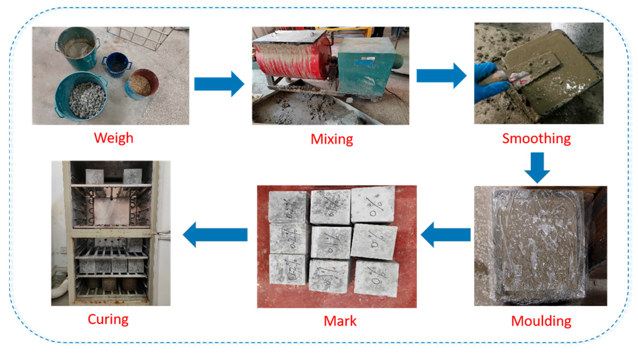
3. Beam Design and Fabrication
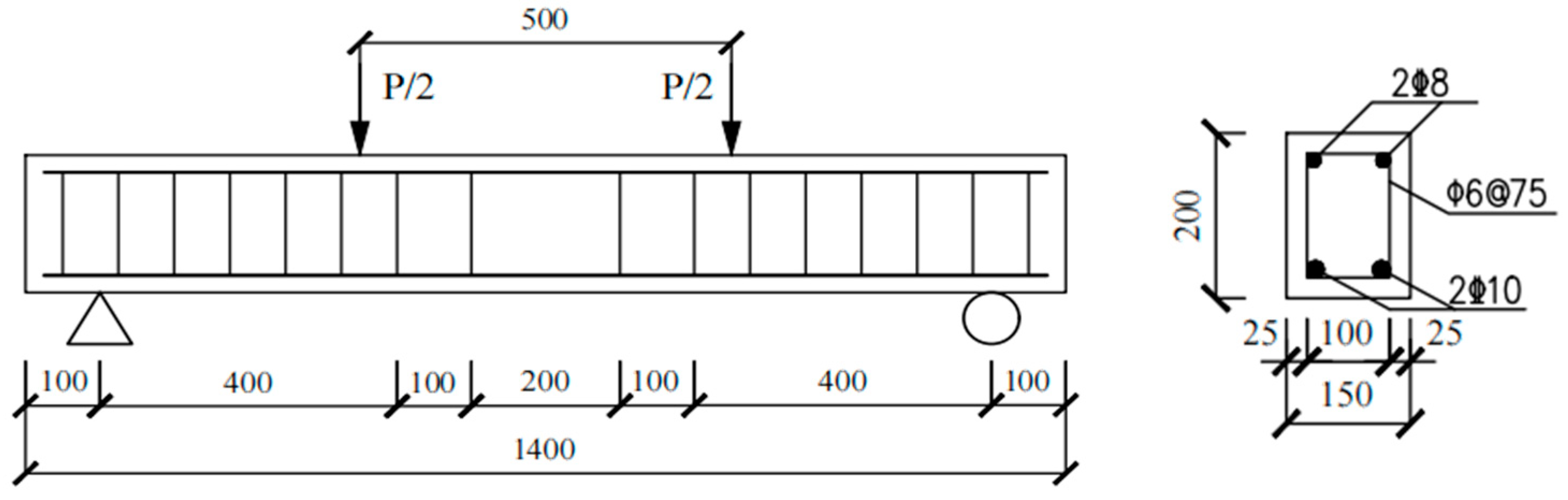
The cross-sectional dimensions of the specimen were b × h = 150 mm × 200 mm, and the total length of the concrete beam was 1400 mm. The support distance from the edge of the test beam was 100 mm. The pure bending length of the beam was 500 mm, and the effective height of the beam was 159 mm, see
Figure 4, on the left. The experiment included one RC beam and three BFRP bar beams. According to the GB 50010-2010 [
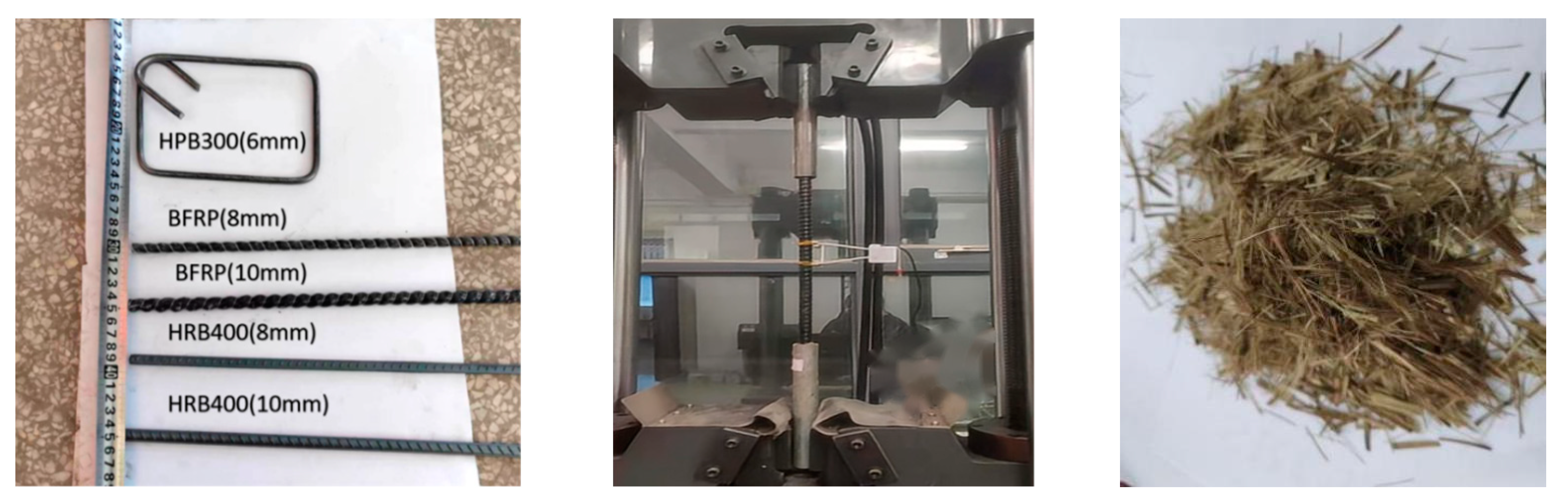
34] standards, the beam type is designated as suitable for reinforcement, with a longitudinal reinforcement ratio of 0.66%. The tension longitudinal bars at the bottom of the specimen were 10 mm in diameter. The stirrups for the specimen were made of HPB300 steel bars with a diameter of 6 mm and spaced at 75 mm intervals. The concrete cover thickness was 25 mm, see
Figure 4, on the right.
The naming convention for each specimen can be represented as MX-k, where the letter “M” indicates the type of longitudinal reinforcement, and the subsequent number “X-k” represents the fiber content. For example, “BX-0.2” means the longitudinal reinforcement is BFRP and the fiber content in the concrete beam is 0.2%. “PX-0.2” indicates that the longitudinal reinforcement is ordinary steel bars, and the fiber content in the concrete beam is 0.2%. The specific specimen parameters are shown in
Table 6.
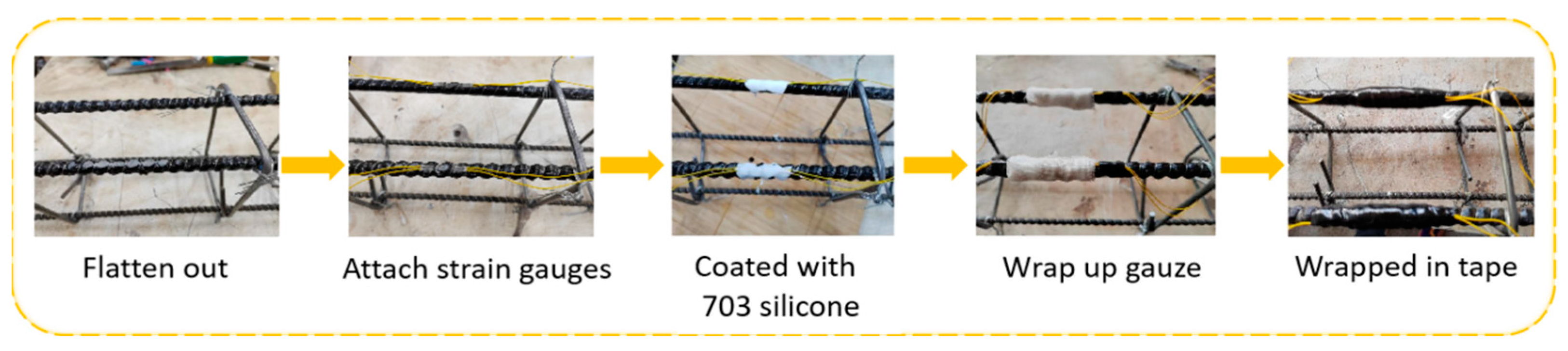
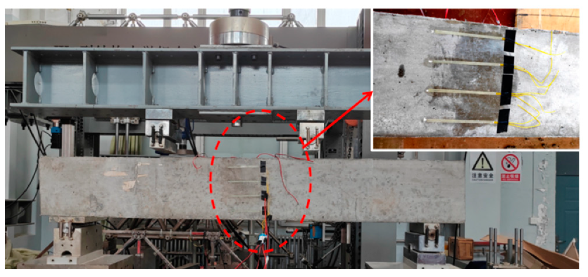
The arrangement of strain gauges (for both steel and concrete) in the beam specimen is shown in
Figure 5. The numbering scheme for measuring the strains in concrete and steel was as follows: Concrete strain gauges were denoted by “Cx,” where the letter “C” represents concrete, and the digit “x” represents the different positions of the concrete strain gauges. The letter “S” stands for steel, followed by the numbers “1 to 4,” indicating the strain gauges on the steel bars near the midspan, symmetrically positioned in pairs. In this test, the strain gauges used for steel reinforcement had the model number BMB120-5AA, with a grid length of 5 mm and a grid width of 3 mm. The specific attachment steps are illustrated in
Figure 6. For the strain gauges on the concrete surface, the model used was BMB120-100AA, with a grid length of 100 mm and a grid width of 3 mm, as shown in
Figure 7.
5. Experimental Result Analysis
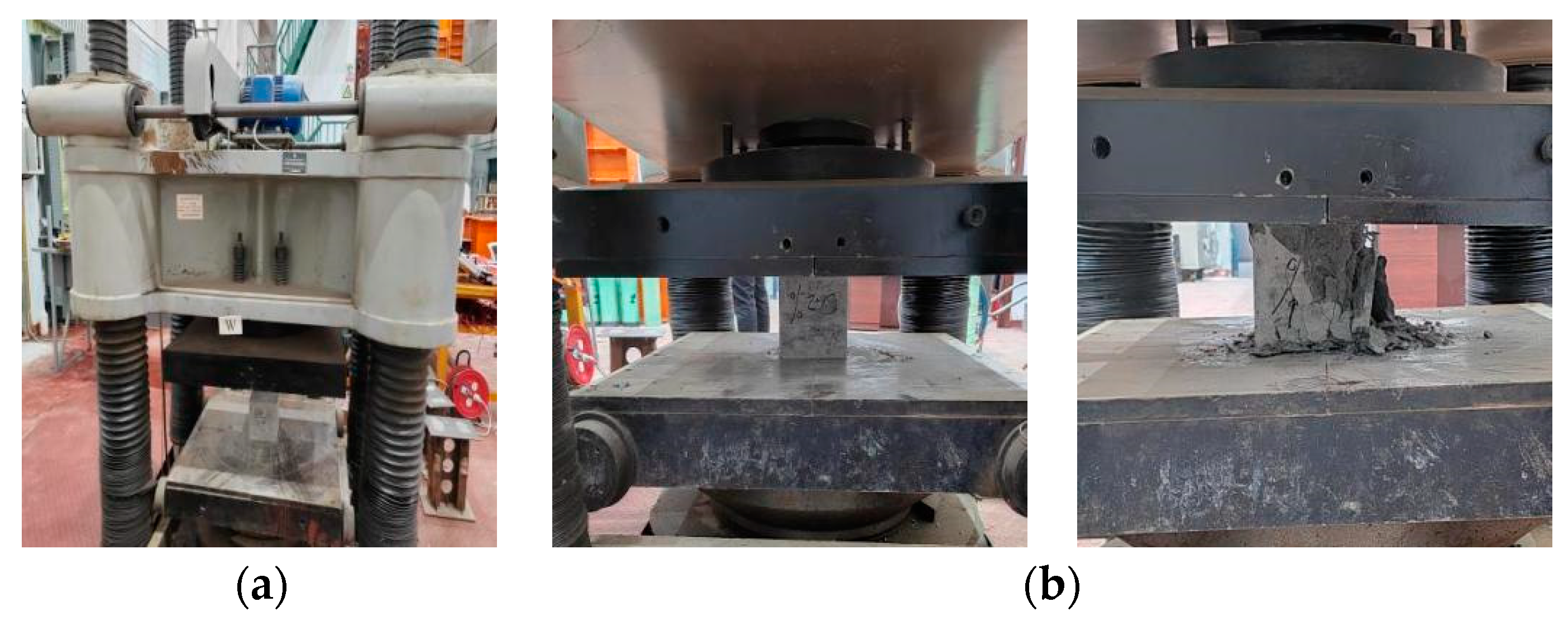
5.1. Failure Mode
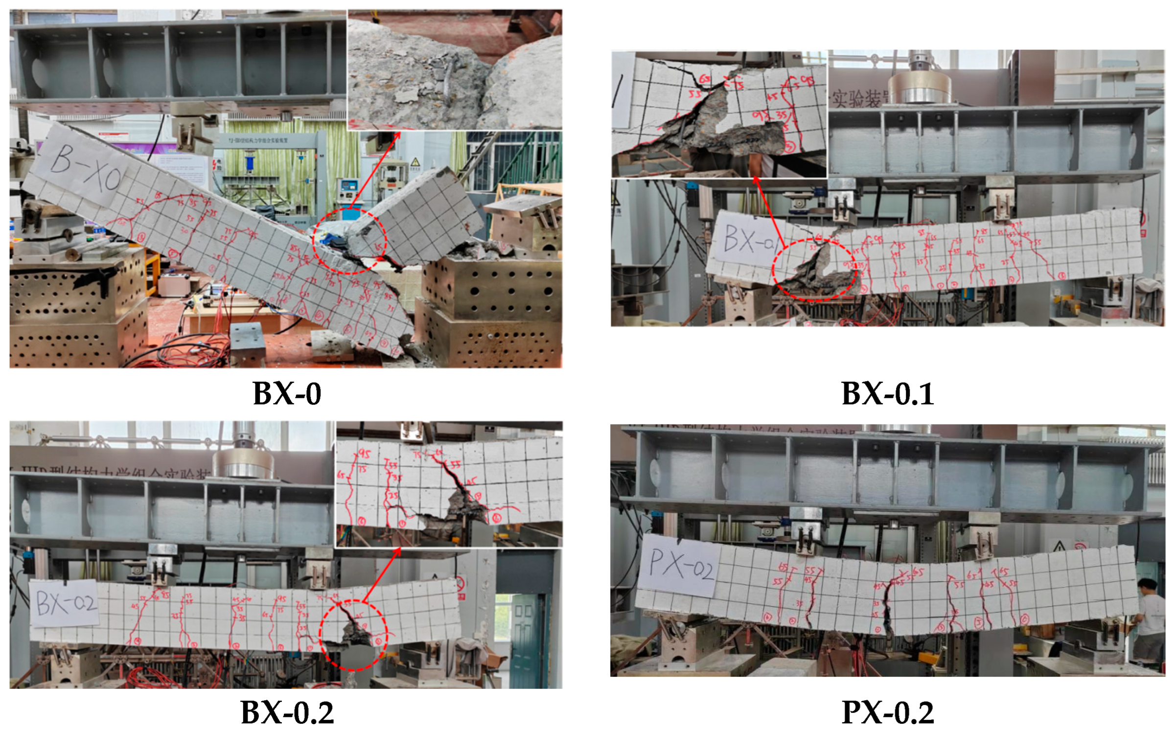
During the experimental loading process, observations were made on the failure process and failure modes of each specimen. The results indicate that the failure mode of BFRP bar beams is characterized by shear brittle failure. Specifically, specimen BX-0 experienced direct fracture failure, while specimen PX-0.2 exhibited flexural failure, as shown in
Figure 10. Further details can be found in
Table 7. Although the design of the experimental beams complies with the relevant standards (GB 50010-2010) [
34] and (GB 50608-2010) [
35], the tensile strength of BFRP bars was two to three times that of HRB400 steel bars, notably increasing the flexural capacity of the specimens. As the load continued to increase, the diagonal shear carrying capacity of the beams gradually approached its limit, leading to shear failure.
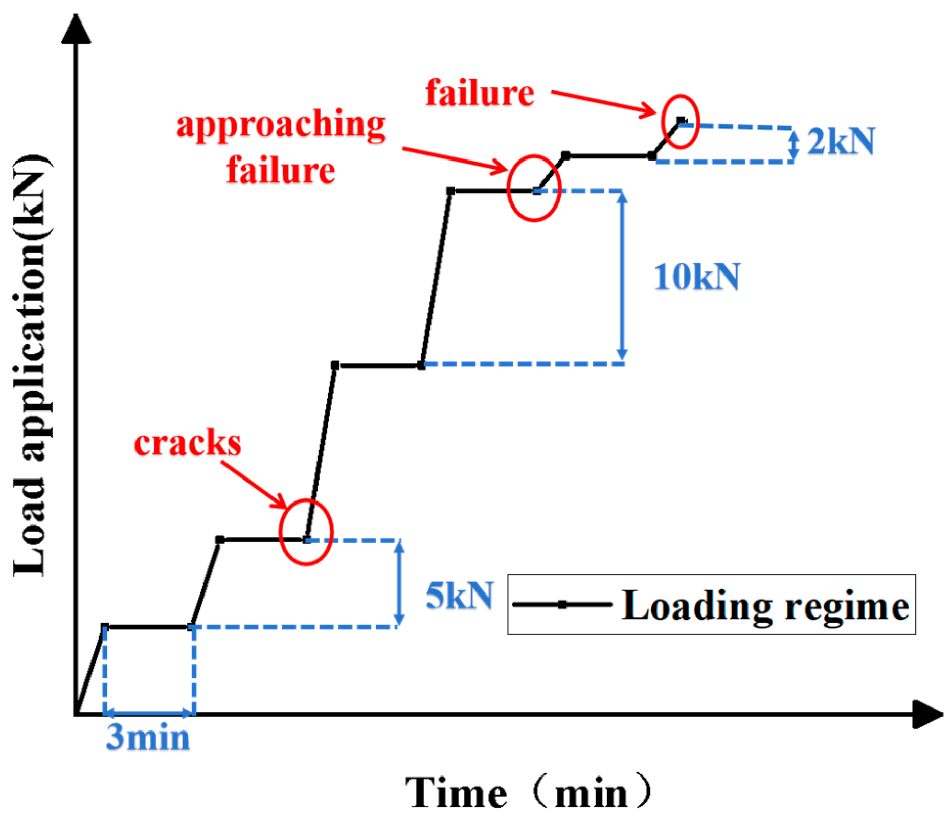
It is noteworthy that the incorporation of fibers yielded a favorable effect in mitigating the extent of damage to the specimens. For instance, specimen BX-0 experienced direct fracture, while specimens BX-0.1 and BX-0.2 exhibited bottom fiber reinforcement fracture. With an increase in the amount of fiber inclusion, the extent of concrete damage gradually decreased. During the loading process, when the load increased to 25 kN, four cracks appeared in BX-0 and three cracks appeared in BX-0.1, while BX-0.2 and PX-0.2 only developed one crack. This indicates that, as the amount of fiber reinforcement increased, the formation and the propagation of cracks in the test beams were delayed. As the load gradually increased to 55 kN to 65 kN, the BFRP bar beams began to exhibit diagonal cracks. When the load was further increased to 95 kN (equivalent to 86% of the ultimate load), continuous faint cracking sounds could be heard from the BFRP bars.
In summary, for the specimen BX-0 without fiber reinforcement, initial vertical cracks emerged, ultimately causing the beam to fracture into two sections upon failure. In contrast, when 0.2% of fiber was incorporated in specimen BX-0.2, the cracking load capacity increased by 18.42% compared to BX-0. During the failure process, the fibers in the lower portion of the beam underwent rupture, but the beam itself remained structurally intact. Consequently, the inclusion of fibers resulted in a delayed initiation of vertical cracks and a reduction in the severity of beam failure, thereby enhancing structural safety and reliability. Furthermore, different types of longitudinal reinforcement yielded distinct failure modes for the beams, with BFRP bar beams exhibiting a brittle failure mode. Nonetheless, when compared to traditional steel reinforcement, the utilization of BFRP bars significantly boosted the beams’ ultimate load-carrying capacity.
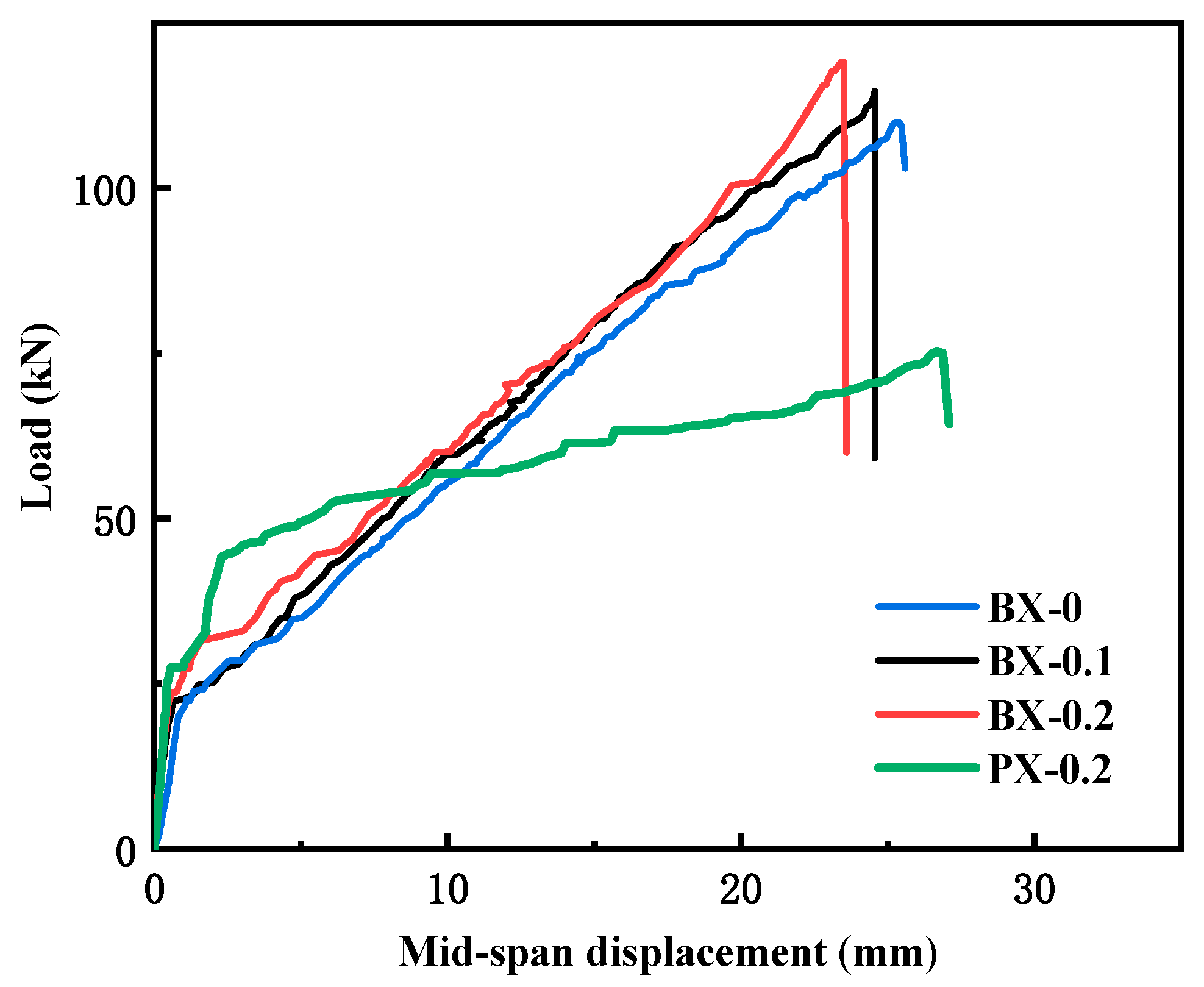
5.2. Load–Deflection Curve at Midspan
The load–deflection curves of four test beams are shown in
Figure 11. Comparing different types of longitudinal reinforcement, it was found that, unlike specimen PX-0.2, the turning points of BFRP bar beams occurred earlier and did not exhibit a clear yield stage. Subsequent to the turning point, it is evident that, when subjected to equivalent displacement, the rate of load increment in the BFRP bar beams significantly surpasses that observed in RC beams. This phenomenon is attributed to the fact that the elastic modulus of BFRP bars is approximately one-fourth that of conventional steel reinforcement, and they manifest a distinct linear elastic behavior under tensile loading, as opposed to traditional steel reinforcement, which exhibits a well-defined yield point. Therefore, with the same amount of fiber reinforcement added, the overall stiffness of steel-reinforced concrete beams is higher than that of BFRP bar beams. However, the use of BFRP bars increases the ultimate load-carrying capacity of the beams. Specimen BX-0.2 exhibited a 58.27% increase in ultimate load-carrying capacity compared to specimen PX-0.2.
The impact of different fiber contents on the beam: Compared to specimens BX-0 and BX-0.1, specimen BX-0.2 exhibited a later turning point. Consequently, augmenting the quantity of fiber reinforcement contributes to the enhancement of the beam’s stiffness, consequently mitigating beam deflection. The maximum midspan displacement of the specimens decreases with an increase in fiber reinforcement content. Therefore, the basalt fibers distributed within the concrete beams can more effectively enhance the overall performance of the beams, thereby reducing beam deformations. The influence of basalt fiber content on the ultimate load-carrying capacity of the beams is not very pronounced. Compared to specimen BX-0 without Basalt Fiber, the ultimate load-carrying capacity increased by 4.24% and 8.27% for specimens BX-0.1 and BX-0.2. However, the impact on the cracking load of the beams was more significant. Compared to specimen BX-0, specimens BX-0.1, BX-0.2, and PX-0.2 exhibited increases in cracking load of 4.77%, 14.29%, and 16.67%.
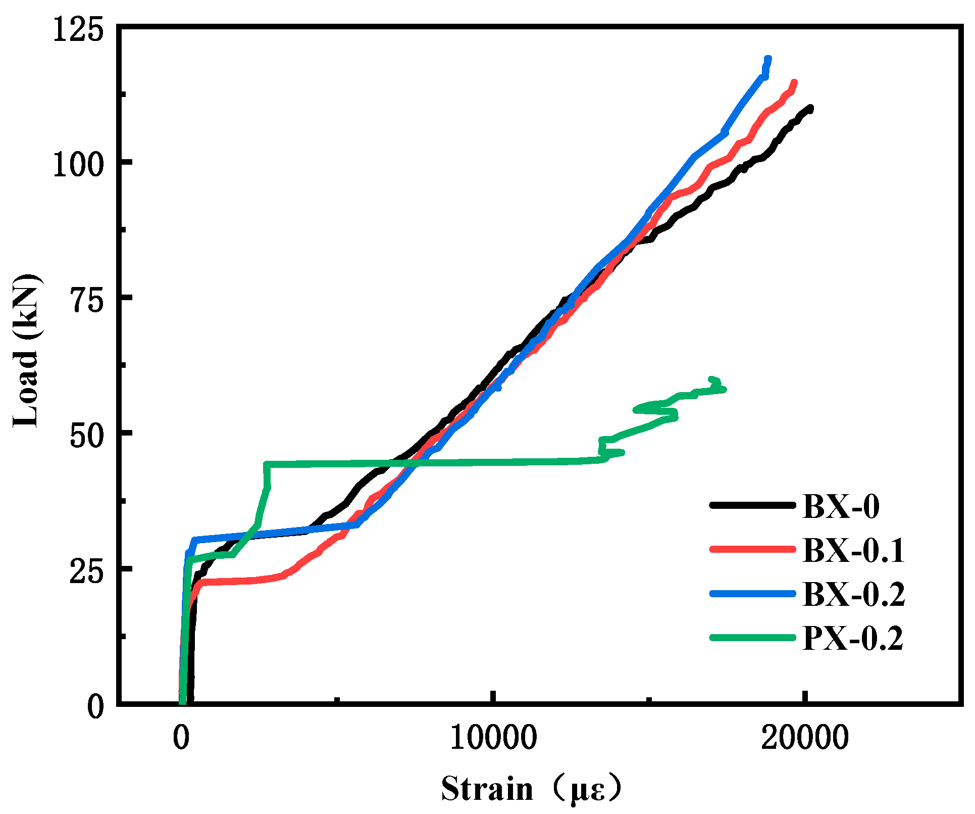
5.3. Load–Strain Curve
Figure 12 presents the load–strain curve for all test beams with longitudinal tensile reinforcement at midspan. This curve undergoes three significant stages of change, with the first stage occurring before concrete cracking: During this phase, the strain exhibited by BFRP bars experiences an increment rate roughly akin to that observed in conventional steel reinforcement. Additionally, with the progressive augmentation of the external load, the longitudinal reinforcement strain remains relatively constant. The second stage is from concrete cracking to just before the steel reinforcement yields: During this stage, the strain in BFRP bars increases significantly more than that in steel reinforcement because the elastic modulus of BFRP reinforcement is smaller than that of steel. Therefore, when subjected to the same load, the strain in the BFRP bars increases at a higher rate than in steel reinforcement. The third stage is from steel reinforcement yielding to beam failure: Steel reinforcement yields and continues to carry the load, resulting in a rapid increase in strain without a significant increase in stress. However, during this time, the strain in a BFRP bar increases with the increase in stress until it ultimately fractures.
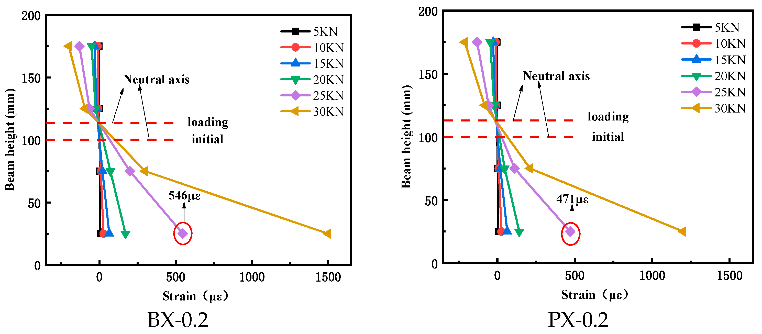
Figure 13 illustrates the strain distribution curves recorded at various measurement points along the midspan cross-section of the test beam. Prior to the occurrence of concrete cracking, these curves displayed a characteristic linear pattern. Subsequent to the initiation of concrete cracking, driven by crack expansion, there was an upward shift in the neutral axis of the beam, accompanied by a marginal reduction in the height of the compressed concrete region. This empirical observation substantiates the validity of assuming a planar cross-sectional behavior. For instance, when subjected to a load of 25 kN, it was noted that, as the fiber content increased, the rate of strain growth at the measurement point located 25 cm above the beam’s base decelerated, signifying a significant decrease in the beam’s cracking rate.
5.4. Calculation of Cracking Moment in a Section
In engineering design and experimental research, it is necessary to determine the value of the cracking load. The calculation method for the cracking moment of fiber-reinforced beams is similar to that of ordinary reinforced concrete beams. When a test beam is subjected to an increasing load, upon reaching the cracking load, the tensile region of the concrete undergoes strain deformation, attaining the ultimate tensile strain, whereas the compressive section of the concrete retains its elastic behavior. Regarding the calculation of the cracking moment, previous researchers have compared different methods for calculating the cracking load. After conducting research, this section selects the cracking moment calculation formula for RC beams provided in the “Code for Design of Hydraulic Concrete Structures” (SL 191—2008) [
36] and combines it with the strength design formula for steel-fiber-reinforced concrete (SFRC) from the (JGJ/T 465—2019) “Standard for Design of Steel Fiber-Reinforced Concrete Structures” [
37]. This combination allows for the determination of the influence coefficient of BFRC beams on the cracking moment.
Referring to the hydraulic engineering code, the cracking moment for reinforced concrete members without the addition of fibers is given by
In the equation, —fundamental value of the plastic moment factor for the cross-section; for a rectangular cross-section, = 1.55;
—standard value of the concrete’s axial tensile strength;
—distance from the centroidal axis of the cross-section to the tensile edge of the test beam;
—longitudinal reinforcement ratio for tensile steel bars;
—ratio of the elastic modulus of steel reinforcement to the elastic modulus of concrete, = /.
In this context, because both steel reinforcement and FRP bars remain in the elastic phase before concrete cracking, the value of can also be effectively replaced by the elastic modulus of the FRP bars.
While JGJ/T 465—2019 may not provide specific provisions for basalt-fiber-reinforced concrete, it is possible to use the tensile strength formula for steel-fiber-reinforced concrete because the reinforcing principle of fibers in concrete remains the same. This allows for the redefinition of the fiber influence coefficient for basalt fiber.
In the equation, —cracking moment of basalt concrete beam;
—basalt fiber characteristics;
—fiber volume fraction;
—fiber length;
—fiber diameter;
—influence coefficient of basalt fiber on concrete cracking moment.
Substituting Equation (5) into Equation (2) yields
wherein define
,
—the impact function of basalt fiber on the cracking moment. After regression calculation,
= 0.089. For basalt-fiber-reinforced beams, it should be noted that, due to the limited enhancement effect of fibers on concrete beams, in accordance with the studies cited in references [
38,
39], it should satisfy
< 1.4.
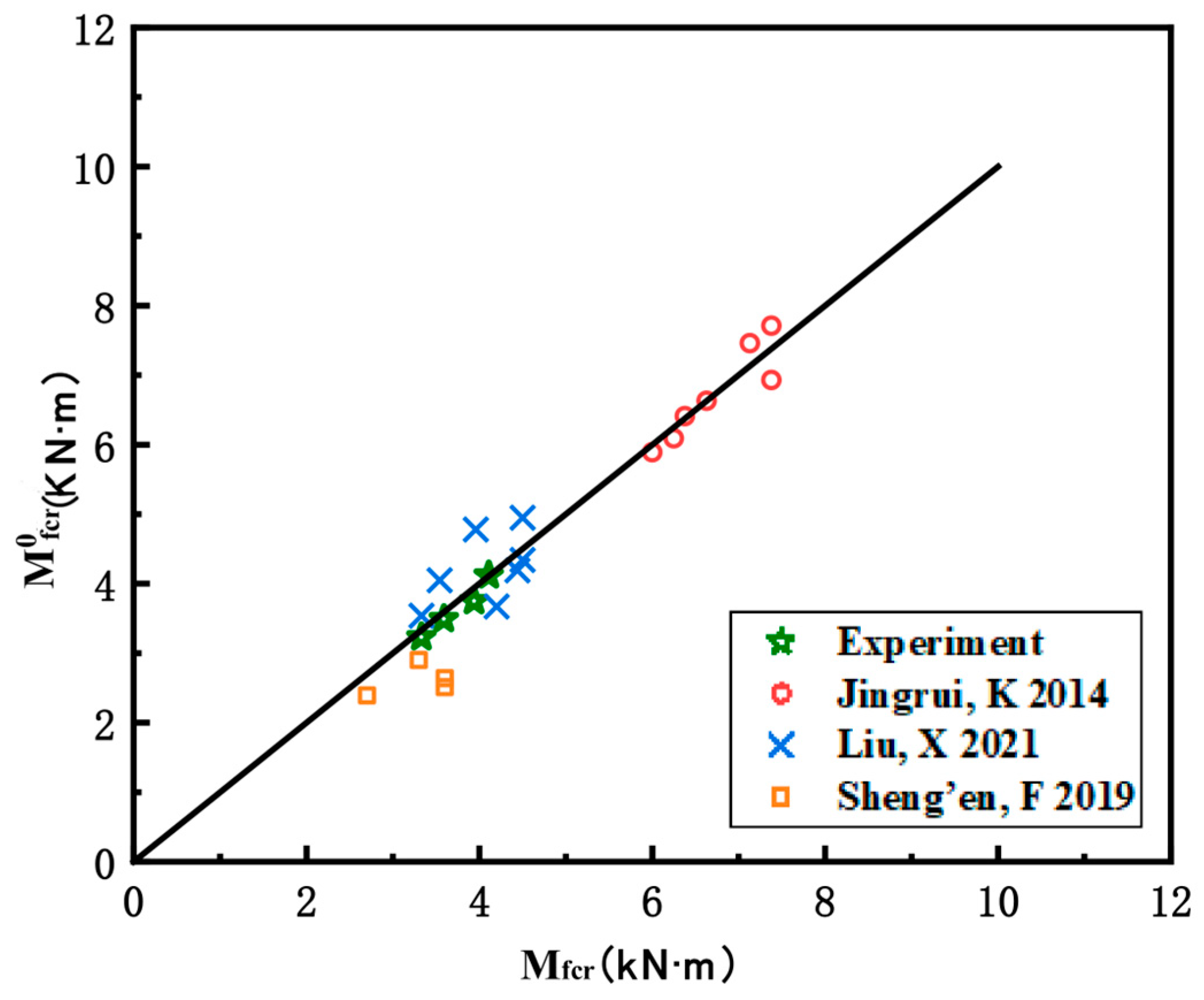
To validate the applicability of Equation (7), a total of 22 sets of experimental data for fiber-reinforced concrete beams were collected, including 18 sets from references [
23,
39,
40] and the additional 4 sets of experimental results presented in this paper. Using Equations (2) and (7), the calculated values M
0fcr of cracking moments for each specimen were obtained and compared with the corresponding experimental values M
fc, as shown in
Table A1 and
Figure 14. After calculations, the average ratio of M
0fcr to M
fc was 0.97, with a standard deviation of 0.53. It can be observed that Equation (7) fits the experimental results well and exhibits relatively low variability.
5.5. Calculation of Ultimate Load Capacity
In accordance with the calculation method specified in ACI 1440.1R-15 [
42], when a beam fails in tension, the concrete does not reach its compressive strength and the strain in the concrete is rather complex, tending toward a conservative consideration. ACI 1440.1R-15 approximates the height of the concrete in the compressed region to the height at which the beam reaches its equilibrium failure, thus resulting in a conservatively estimated ultimate load for the beam. The specific calculation formula is as follows:
where
—ultimate compressive strain of concrete;
—FRP bars’ area;
b—cross-sectional width;
d—effective depth of the cross-section;
—tensile strength of FRP reinforcement;
—correction factor.
When the compressive strength of concrete is not greater than 27.58 MPa, the correction factor is taken as 0.85. When the compressive strength exceeds 27.58 MPa, for each increase of 6.895 MPa in strength, the factor decreases by 0.05.
Equation (9) is used to calculate the ultimate load of the PX-0.2 specimen, as BX-0, BX-0.1, and BX-0.2 experienced shear failure, and therefore, the flexural capacity calculation cannot be applied. In this case, the calculation is performed using the shear capacity calculation for inclined sections of flexural members as specified in GB 50010-2010 [
34]. The calculation formula is as follows:
where
—design value of concrete axial tensile strength;
—shear span-to-depth ratio,
—cross-sectional width,
—effective depth of the cross-section;
—design value of tensile strength of stirrups;
—total cross-sectional area of all stirrups within the same section.
The calculated ultimate load closely matched the experimental results, indicating that Equations (9) and (10) can predict the ultimate load of the beam with reasonable accuracy and provide a certain level of safety assurance. The results are presented in
Table 8.
6. Conclusions
This article presents a four-point bending test on BFRP bar BFRC beams. This study investigates the effects of variables such as the dosage of basalt fiber (0%, 0.1%, and 0.2%) and the type of longitudinal reinforcement (steel bars and BFRP bars) on the failure mode, cracking moment, and ultimate load-carrying capacity of the tested beams. Based on the experimental results, the following conclusions are drawn:
- (1)
Compared to specimens BX-0, which had no basalt fiber reinforcement, specimens BX-0.1 and BX-0.2 exhibited an increase in ultimate load-carrying capacity of 4.24% and 8.27%, respectively. Additionally, their cracking loads increased by 7.89% and 18.42%, respectively. Therefore, it can be concluded that the addition of basalt fiber in these BFRP bar BFRC beams does not significantly enhance the ultimate load-carrying capacity but has a more noticeable effect on increasing the cracking load.
- (2)
When the dosage of basalt fiber remained below 0.2%, augmenting the fiber dosage resulted in a progressive diminishment of the extent of beam failure. This indicates that the basalt fibers, uniformly dispersed within the concrete, effectively enhance crack resistance, thereby improving the overall integrity of the beam and reducing the extent of damage.
- (3)
Under the same dosage of basalt fiber, specimen BX-0.2 exhibited a 58.27% increase in ultimate load-carrying capacity compared to specimen PX-0.2. However, the cracking load decreased by 4%, which suggests that the incorporation of BFRP (Basalt-Fiber-Reinforced Polymer) bars in the beams exerts a notable influence on augmenting the ultimate load-carrying capacity, whereas it exerts minimal influence on the cracking load.
- (4)
A cracking moment calculation formula for BFRC beams was proposed through regression analysis. When the influence coefficient of basalt fiber, denoted as “” was set to 0.089, the model’s calculated values exhibited a satisfactory concordance with experimental data. Furthermore, the ultimate load-carrying capacity of four beams was calculated according to relevant standards, and the calculated values matched the experimental results.
The main focus of this study was to investigate the influence of basalt fiber content on BFRP bar beam behavior. The research findings indicated that the addition of fibers effectively increased the ductility and tensile strength of concrete, restrained crack propagation, and improved the ultimate failure mode of BFRP-reinforced beams. While this study conducted partial experimental research and theoretical analysis, there are still many aspects that require further in-depth investigation and refinement.
The parameters considered in this study, such as concrete strength grade, reinforcement ratio, and beam dimensions, were relatively limited in scope. Therefore, the applicability of the conclusions to other types of fiber-reinforced concrete beams, such as over-reinforced beams, under-reinforced beams, high-strength concrete beams, T-shaped beams, and so forth, still necessitates further research.


