Article

Effect of Shield-Tunnel Construction on the Horizontal Response of Adjacent Piles in a Silty Layer

1
Zhengzhou Metro Group Co., Ltd., Zhengzhou 450000, China
2
Zhongzhou Water Holding Co., Ltd., Zhengzhou 450000, China
3
Zhengzhou Engineering Quality Supervision Station, Zhengzhou 450000, China
4
China Railway No. 5 Engineering Group Co., Ltd., Zhengzhou 450000, China
5
College of Civil Engineering, Henan University of Technology, Zhengzhou 450001, China
*
Author to whom correspondence should be addressed.
Buildings 2023, 13(10), 2455; https://doi.org/10.3390/buildings13102455
Submission received: 6 June 2023 / Revised: 4 August 2023 / Accepted: 1 September 2023 / Published: 27 September 2023
(This article belongs to the Section Building Structures)

Abstract

:
This paper studies the problem of shield tunnels laterally passing through piles based on in situ tests and numerical methods. The effects of vertical load, pile–tunnel distance, and tunnel-cover depth on the horizontal displacement and the bending moment of adjacent piles were investigated. The results show that the shield tunnel induced adjacent pile displacement toward the tunnel side near the tunnel axis, and the soil below and above the tunnel axis constrained the pile, displacing toward the tunnel side. The maximum values of the horizontal displacement and bending moment were at the tunnel axis. The vertical load on the cap had little influence on the horizontal response of the pile. The main influence area induced by shield construction was located within 1.5 times the tunnel diameter. The maximum horizontal displacement and maximum bending moment were reduced by 36–45% and 45–78% on the far pile due to the shading effect induced by the near pile. The tunnel-cover depth had a significant influence on the distribution patterns of the horizontal displacement and the bending moment. The positions of the maximum horizontal displacement and the maximum bending moment moved downward with increases in tunnel-cover depth. The maximum horizontal displacement and bending moment increased with increases in tunnel-cover depth.

1. Introduction

With the boom in urban-subway construction, tunnels often have to pass through pile foundations. Shield construction displaces the soil around tunnels, subsequently inducing horizontal displacement and bending moments on the adjacent pile foundations, affecting the bearing capacity of the pile foundation. Therefore, it is vital to study the influence of shield construction on the horizontal response of adjacent pile foundations.
The effects of shield tunnels on the responses of adjacent piles have been studied through the use of theoretical analyses, model tests, and numerical methods. In the field of theoretical analysis, Sagaseta proposed analytical solutions for the strain field in initially isotropic and homogeneous incompressible soil induced by near-surface ground loss [1]. Park assumed oval-shaped ground deformation in the tunnel section and proposed elastic solutions to predict tunnel-induced ground-surface deformation in soft ground [2]. Pinto determined ground mass displacement based on uniform convergence and the ovalization displacement mode of a tunnel’s cavity wall and then put forward simplified analytical solutions to predict ground displacement induced by the presence of shallow tunnels in soft soil [3]. Loganathan introduced gap parameters into the prediction of ground movements to redefine equivalent ground-loss parameters, estimated the displacement around a tunnel, and then applied it to the pile, proposing a two-stage method [4,5]. Chen studied the lateral and axial responses of piles caused by tunneling using a two-stage method, first by assessing free-field soil movements based on the analytical method, and then by estimating pile responses through the boundary-element method [6]. Huang assumed no slippage at the soil–pile interface, adopted the Winkler model to simulate pile–soil interaction, and investigated the impact of tunnel construction on adjacent piled buildings through a simple two-stage method [7]. Zhang took pile–pile interaction and the coupling of longitudinal–lateral deformation into consideration and proposed the two-stage method to investigate the behavior of pile groups with rigid elevated caps subjected to tunnel-induced ground movements [8]. Cheng introduced the BoxLucas1 exponent model into a two-stage method to describe the nonlinear interaction between pile and soil and studied the skin friction and axial force on the adjacent pile [9]. Zhang considered the effects of the lateral displacement of soil, proposed a simplified solution based on Pasternak’s foundation model, and estimated the lateral displacements and internal forces of single pile and group piles induced by tunnel construction [10]. Franza considered the stiffness of superstructure and pile–soil interactions and studied the effects of the vertical load and tunnel on adjacent pile groups through a two-stage method [11]. Liu tuned a U-shaped tunnel into the circle tunnel using the conformal mapping method, studied the response of the pile influenced by the U-shaped tunnel, and determined the displacement and stress of the soil and pile through the complex-variable-function method [12]. Chen took the loss of pile–soil interaction due to the tunnel-induced exposure of a pile and studied the vertical response of the pile adjacent to the tunnel [13].
In the field of model tests, Loganathan modeled the tunnel-excavation procedure using equivalent ground-loss values, which were achieved by reducing the diameter of the model tunnel, studied tunnel-induced ground displacement in clays and the effects on adjacent piles through a centrifuge model test, and then investigated the influence of tunnel depth on ground movements, the axial force of the pile, the settlement, and the lateral deformation of the pile [14]. Jacobsz studied the effect of a tunnel on an adjacent single pile in dense sand through the use of a centrifuge model test and investigated the ground-surface-settlement profile and large settlement zone [15]. Lee studied the ground movements induced by tunnel construction and the influence on adjacent structures through a two-dimensional model test and analyzed the pile-tip settlement and influence zone [16]. Chiang studied the skin friction, end-bearing capacity, and bending moment of piles adjacent to a tunnel under various working loads in sand [17]. Ng studied the effect of a twin-tunnel-construction sequence on an existing single pile in sand and investigated the settlement and capacity loss in terms of the pile induced by the tunnel construction [18,19]. Lu investigated twin tunnel passes in an existing 2 × 2 piled raft in sand, using a centrifuge test [20]. He simulated tunnel construction through the use of a micro-shield machine, investigated shield tunnels on 2 × 2 pile groups, and determined the internal force and displacement properties of piles [21].
In the field of numerical simulation, Mroueh studied the influence of tunnel construction on adjacent piles through the elastoplastic three-dimensional finite-element method and investigated the position of the pile tip and the influence of the distance of the pile axis from the tunnel center on the internal force of the pile [22]. Lee studied the influence of advancing open-face tunnel excavation on existing piles through the use of a three-dimensional elastoplastic-coupled consolidation numerical method, suggested the influence zone near the excavation face, and obtained a relative subsurface settlement, the side shear stresses, and pore pressure on the foundation [23]. Liu studied the effects of slurry pressure, grouting pressure, grouting material hardening, and soil–pile interaction on the movement of pile groups induced by the shield-construction process via the nonlinear finite-element method [24]. Based on the three-dimensional coupled-consolidation finite-element method, Soomro investigated the load-transfer mechanism between piles in a group and analyzed the settlement and tilt of the pile group related to the adjacent shield-tunnel excavation [25]. Cheng simulated the tunnel-shield-construction process by applying displacements to a tunnel cavity wall and applied the displacement-controlled finite-element method to assess the effects of tunnel excavation on adjacent piles [26]. Xu studied the responses of vertically loaded piles subjected to passive loads via the three-dimensional coupled-boundary -element method and proposed theoretical expressions for soil movement [27]. Kitiyodom treated piles as elastic beams and soils as interactive springs, modeled pile–soil–raft interactions based on Mindlin’s solutions, developed a simplified numerical method, incorporated these findings into a computer program, PRAB, and then assessed the deformation and load distribution of a piled raft subjected to ground displacements induced by tunneling [28]. Soomro took the stress path and strain-dependent soil stiffness into consideration when investigating the construction sequence of a twin-stacked tunnel in response to a single pile [29]. Li simulated the anisotropic properties of clay through the use of the NGI-ADP model, studying the passive response of a pile adjacent to a tunnel [30]. Li studied the passive response of a pile adjacent to an excavation using the p-y-curve method [31]. Gu investigated pile response caused by tunnel construction considering the effect of the spatially variable property of clay [32]. Zheng studied the load-transfer mechanism of a pile in soft clay induced by tunneling on the pile side and below the pile tip [33]. Sazid simulated rock with a generalized Hoek-and-Brown failure criterion when studying the behavior of tunneling in weak rock with a shallow burial depth, indicating that the stress and strain around the tunnel were redistributed during construction, severely affecting the floor of the lining [34,35,36].
In the present study, the research on the response of an adjacent pile foundation caused by tunnel construction mainly focused on sand and soft soil and seldom considered the effects of vertical loads on pile caps. In this study, we simulated the supports of the excavation face, segment construction, and grouting-condensation processes in tunnel construction through the use of a numerical method and studied the problem of lateral tunnel passes through a pile foundation in a silt layer. The effect of the vertical load on the cap, the pile–tunnel distance, and the tunnel-cover depth on the horizontal displacement and bending moment of the adjacent pile were investigated. This research provides a basis for the engineering design and construction of piles and shield tunnels.

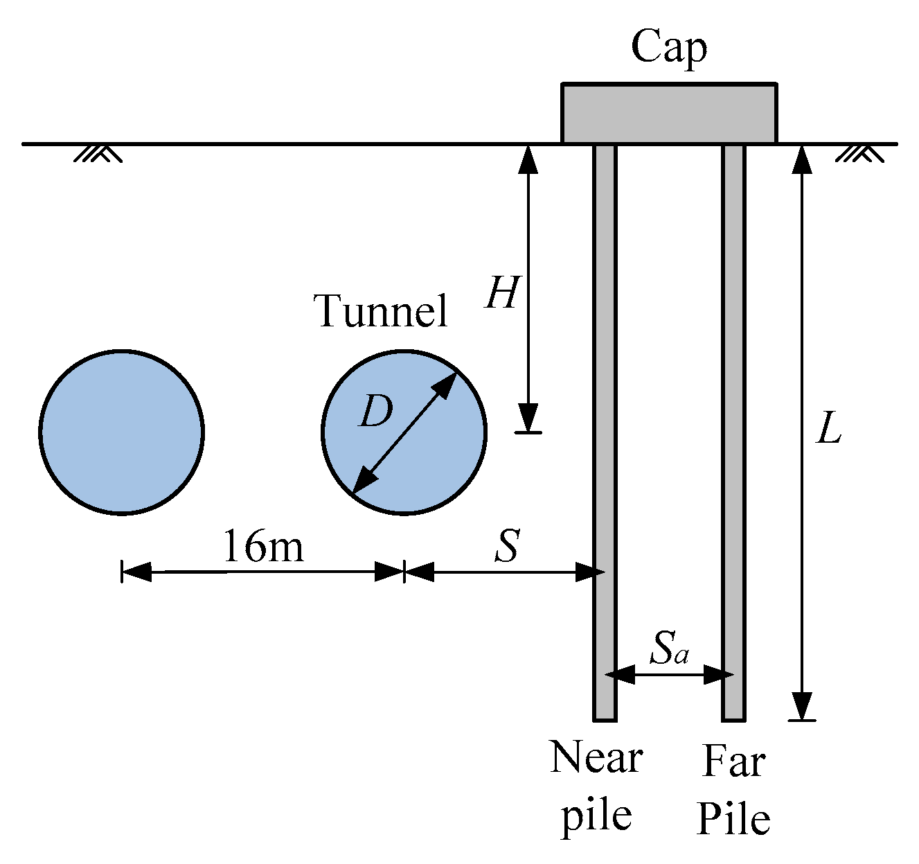
2. Overview of Project

The tunnel in Zhengzhou Metro Line 4 laterally passes through the Jialu River’s bridge pile. The outer diameter of the tunnel is 6 m, the distance between the centers of the twin tunnels is 16 m, the tunnel-cover depth is 12 m, and the side length and height of the cap are 4.8 m and 2 m, respectively. Four piles are uniformly spaced and arranged under the cap; the pile diameter is 0.8 m, the pile spacing is 3.2 m, the pile length is 24 m, and the pile–tunnel-center distance is 7.5 m. The Jialu River bridge was constructed in advance, and shield-tunnel construction was carried out after the designed strength of the pile concrete was achieved. An illustration of the tunnel adjacent to the bridge pile is shown in Figure 1. In this paper, the effect of shield construction on the horizontal response of the adjacent pile under the influence of the vertical load on the cap, pile–tunnel distance, and tunnel-cover depth is studied.

3. Numerical Simulation

3.1. Material Parameters of Soil and Structure

According to a geological survey conducted as part of the project, the foundation soil mainly comprises miscellaneous fill soil, clayey silt, silt, and fine sand. The pile foundation is embedded in miscellaneous fill soil and clayey silt layers, and the tunnel is embedded in clayey silt. The Mohr–Coulomb elastoplastic constitutive model was used to simulate the mechanical properties of the soil. The physical and elasto–plastic mechanical parameters of the soil are shown in Table 1. The cap and pile foundations are made of cast-in-place concrete material; the elastic modulus is 32 GPa and the Poisson’s ratio is 0.2. The tunnel segments were constructed using precast concrete; the elastic modulus is 34.5 GPa and the Poisson’s ratio is 0.24. After the soil was excavated, tunnel segments were assembled in the foundation, and then grouting material was injected between the tunnel segments and the soil. In the numerical simulation, the setting process of the grouting material was simulated using the stiffness-migration method: at the early stage after the grouting, the modulus of the grouting material was low, and it was taken as 0.1% of the modulus of the surrounding soil. After the initial set, the modulus of the grouting material was taken as 1.8 MPa; after the set was completed, the modulus of the grouting material was taken as 400 MPa [37,38].

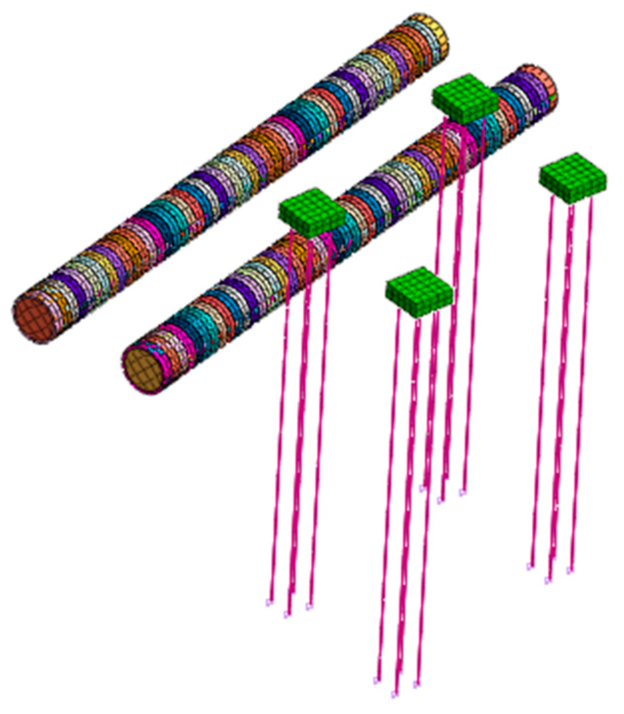
3.2. Numerical Modeling

The MIDAS program is applied in finite-element calculations. A numerical model of the Zhengzhou Metro Line 4 tunnel passing through the Jialu River’s bridge-pile foundation was developed. The dimensions of the numerical model are as follows: the length of the tunnel was 75 m (i.e., 50 pieces of tunnel ring), and the distances between the model boundary and the structures were more than 5 times greater than the tunnel diameter, based on Mair’s theory [39]. The length of the pile was 24 m, and the height of the model was 85 m. Out-of-plane displacement boundary conditions were assumed on the four sides of the model, and a pinned boundary condition was assumed at the bottom of the model. The numerical model of the shield tunnel adjacent to the pile foundation is shown in Figure 2.
According to the construction procedure of the project, the following steps were taken in the numerical simulation: (1) balancing of the ground stress to obtain a stratum with consolidation stress and no displacement; (2) construction of the bridge pile and cap in the foundation; (3) excavation of the soil and construction of the tunnel using the progress-softening method, and supporting the excavation face using in situ earth pressure; (4) simulation of the setting process of the grouting material between the tunnel segment and the soil using the stiffness-migration method; (5) and the application of a vertical load on the cap to simulate the weight of the pier, bridge, and traffic load.

3.3. Numerical Calculation Scheme

Through the proposed numerical model, the influence of the vertical load, the pile–tunnel distance, and the tunnel-cover depth on the horizontal displacement and bending moment of the piles was studied. The vertical loads N applied to the cap were 100, 500, 1000, 1500, and 2000 kN. The pile–tunnel distances S were 6, 7.5, 9, and 12 m, i.e., the ratios of the pile–tunnel distance to the tunnel diameter S/D were 1, 1.25, 1.5, and 2, respectively. Since the tunnel-cover depth H is usually more than twice the tunnel diameter in a subway project, the paper focused on a case in which a tunnel laterally passes through piles; therefore, the tunnel axis is located at a depth that is twice as large as the tunnel diameter and, 12, 16, 20, and 24 m above the pile tip, respectively.

4. Results and Discussion

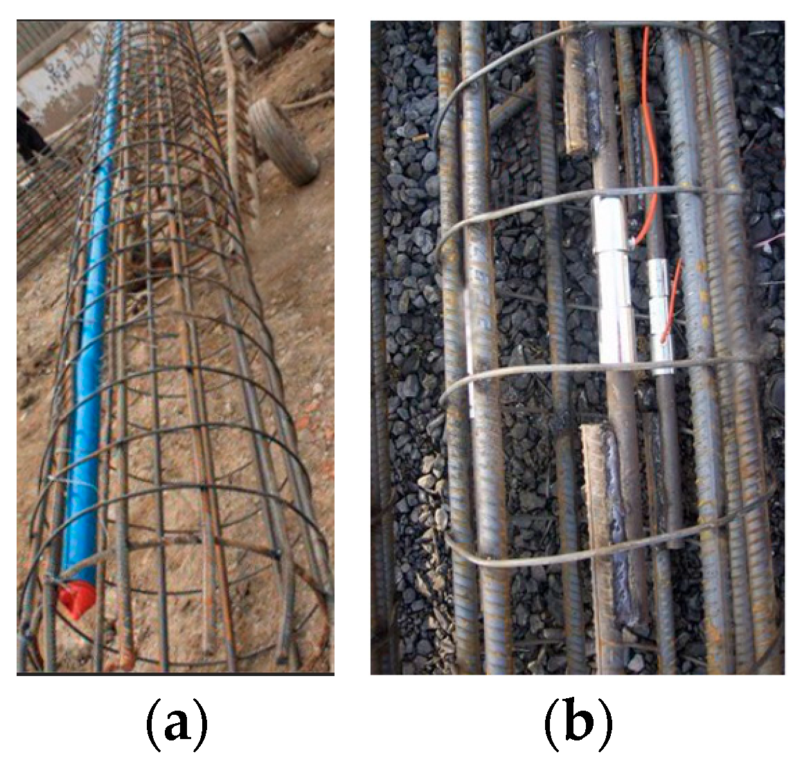
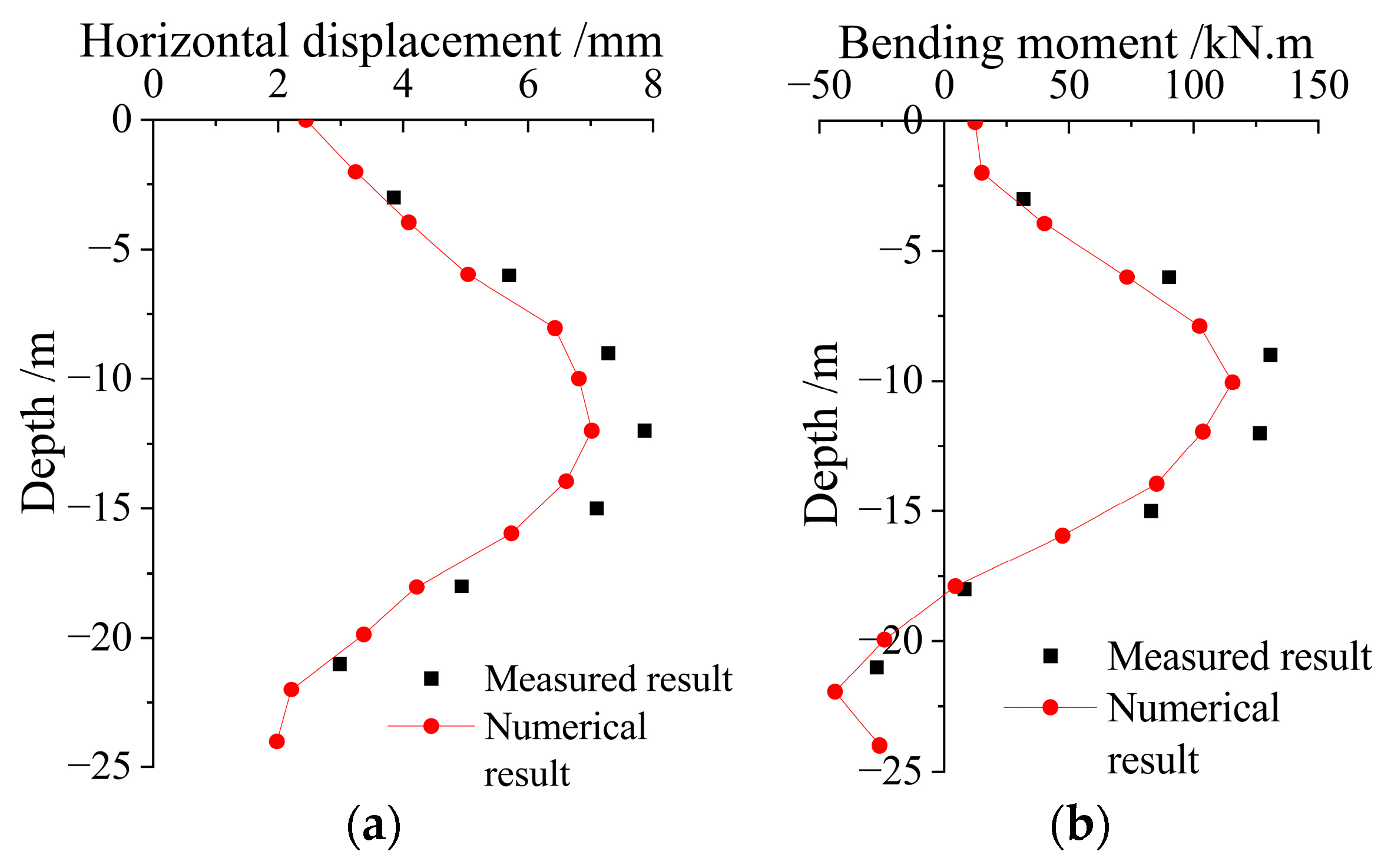
4.1. Field-Test Results

In order to verify the proposed numerical model, an in situ test was conducted on the Jialu River’s bridge pile under the guidance of the customer-relationship management (CRM) method [40]. Before construction of the pile, lateral inclinometer gauges and reinforcement stress gauges were fixed to the piles, as shown in Figure 3. The horizontal displacement on the pile was measured using an inclinometer, the axial strain on the rebar during the shield construction was measured using stress gauges, and the bending moment of the pile was obtained based on elastic theory [41,42]:
M = E c I 0 E s d σ s , o σ s , i
where Ec and Es are the elastic modulus of the concrete and rebar, respectively, d is the diameter of the pile, I0 is the inertia moment of the pile, and σs,o and σs,i are the axial stress on the outside and inside of the pile, respectively, as measured using the stress gauges on the rebar.
After the tunnel construction was completed and the deformation reached stabilization, the in situ test started. The measured and calculated horizontal displacement and bending moment of the pile near the tunnel side (hereafter referred to as near pile) are shown in Figure 4. It can be seen from the figure that due to the construction of the shield tunnel, there is evidence of the generation of large horizontal displacement and bending moment on the pile near the tunnel axis, and the numerical result is in good agreement with the measured result.

4.2. Numerical Results of Horizontal Displacement on Adjacent Pile

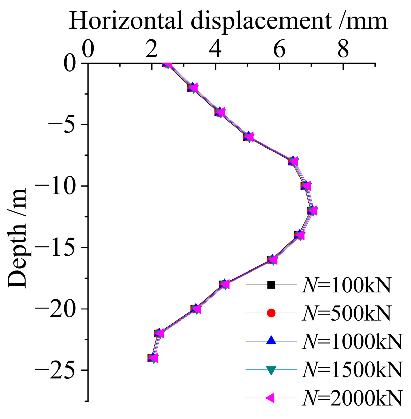
4.2.1. Effect of Vertical Load on Cap

Vertical loads of 100, 500, 1000, 1500, and 2000 kN were applied to the pile cap with a tunnel-cover depth of 12 m and a pile–tunnel distance of 7.5 m. Figure 5 shows the horizontal displacement near the pile caused by the shield tunnel under different vertical loads. It can be seen from the results that the shield-tunnel construction caused pile displacement toward the tunnel side, and the vertical load on the cap had little influence on the horizontal displacement of the pile. The horizontal displacement on the top of the near pile was about 2.5 mm, and it subsequently increased with the increase in depth; the maximum horizontal displacement was about 7.1 mm, located at the tunnel axis, while below the tunnel axis, the horizontal displacement decreased sharply with the increase in depth, and the horizontal displacement at the pile tip was about 2 mm.

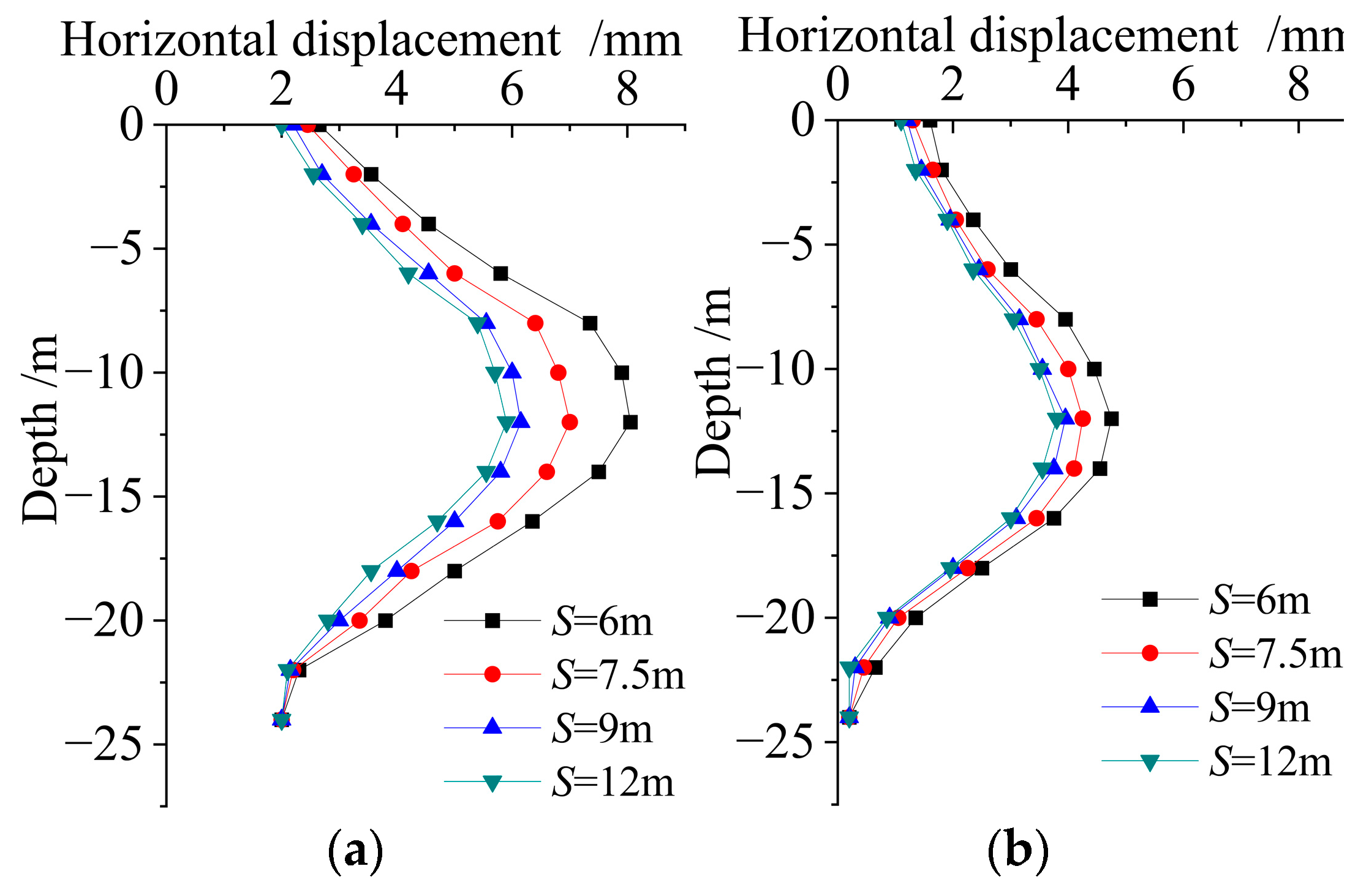
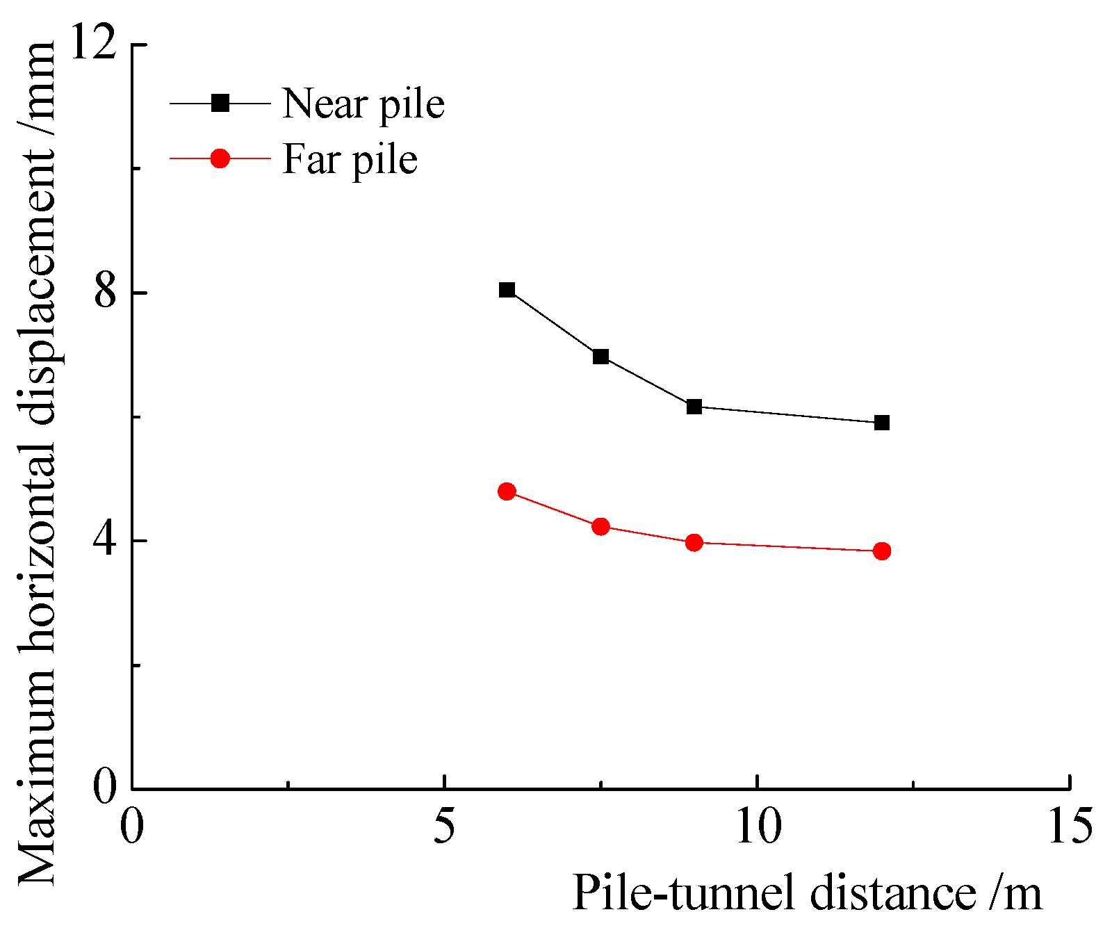
4.2.2. Effect of Pile–Tunnel Distance

Pile–tunnel distances of 6, 7.5, 9, and 12 m were studied under conditions in which the tunnel-cover depth was 12 m and the vertical load was 500 kN. The influence of the pile–tunnel distance on the horizontal displacements of the near pile and far pile are illustrated in Figure 6. The results show that the near pile and far pile moved toward the tunnel side, and the horizontal-displacement curve had similar features at different pile–tunnel distances. The maximum value of the horizontal displacement was on the tunnel axis, while it is small on the top and tip of the pile. When the pile–tunnel distance varied, the horizontal displacement varied significantly on the near pile, while it varied slightly on the far pile. The horizontal displacement of the far pile was significantly smaller than that of the near pile, indicating that the near pile had a shading effect on the far pile.
The influence of the pile–tunnel distance on the maximum horizontal displacement of the pile is shown in Figure 7. It can be seen from the figure that when the pile–tunnel distance ranged between 6 and 9 m (1–1.5 D), the maximum horizontal displacement on the near pile decreased significantly with the increase in the pile–tunnel distance. When the pile–tunnel distance was greater than 9 m (1.5 D), the maximum horizontal displacement on the near pile changed slightly, indicating that the main influence area on the adjacent pile was within 1.5 times that of the tunnel diameter. The maximum horizontal displacement on the far pile varied slightly due to the shading effect induced by the near pile. The maximum horizontal displacements on the near pile and far pile were 8.1 and 4.8 mm, respectively, when the pile–tunnel distance was 6 m, indicating that the maximum horizontal displacement on the far pile was reduced by 41% due to the shading effect. As the pile–tunnel distance increased to 12 m, the maximum horizontal displacements on the near pile and far pile were 5.9 and 3.8 mm, respectively, and the maximum horizontal displacement was reduced by 36% on the far pile.

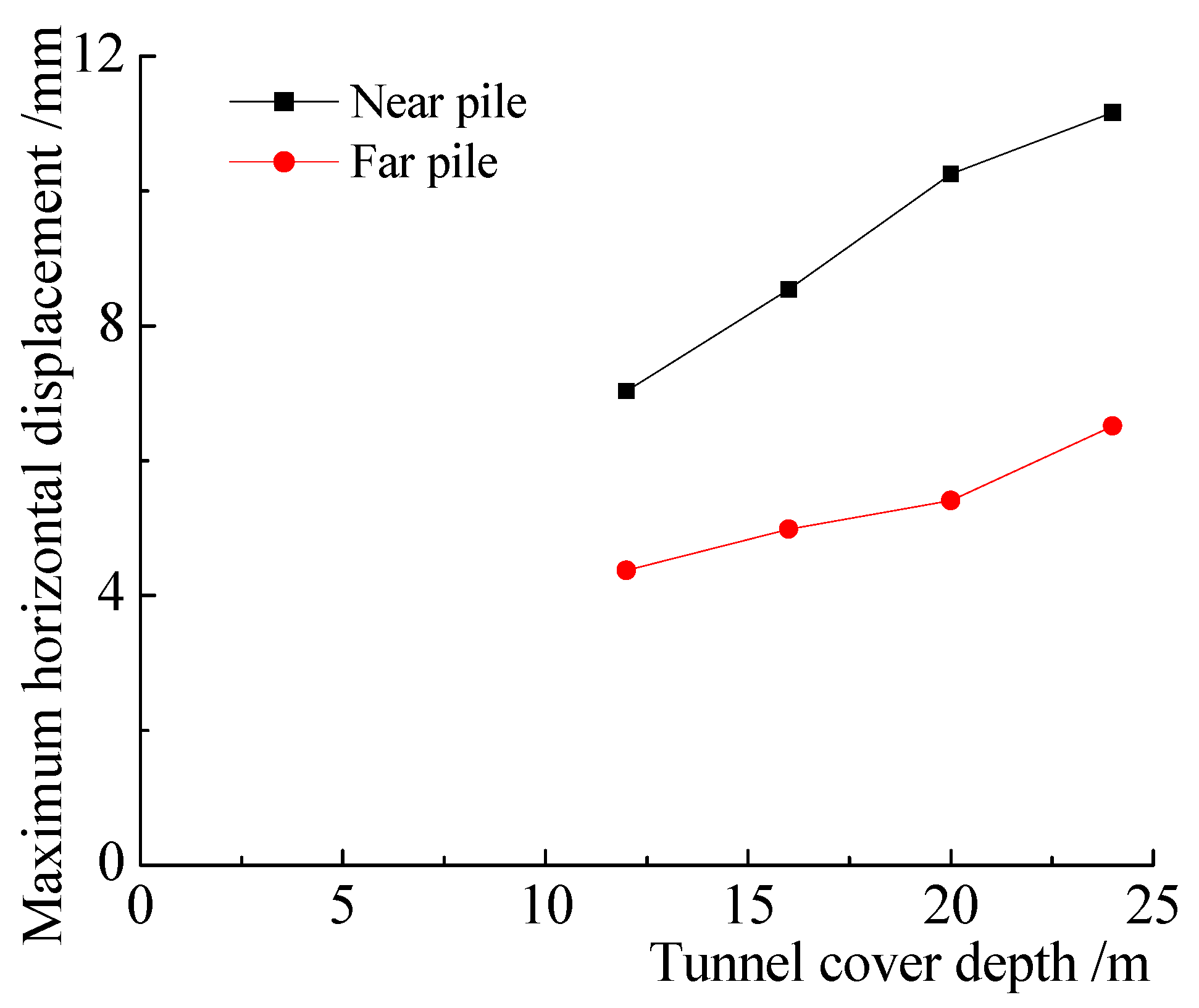
4.2.3. Effect of Tunnel-Cover Depth

Tunnel-cover depths of 12, 16, 20, and 24 m were investigated with a pile–tunnel distance of 7.5 m and a vertical load of 500 kN. The influence of the tunnel-cover depth on the horizontal displacement of the pile is shown in Figure 8. It can be seen from the results that the maximum horizontal displacement on the pile was located at the tunnel axis. With the increase in tunnel-cover depth, the maximum horizontal-displacement position moved downward continuously.
The influence of the tunnel-cover depth on the maximum horizontal displacement of the pile is shown in Figure 9. It can be seen from the figure that the maximum horizontal displacement on the near pile and far pile generally increased linearly with the increase in the tunnel-cover depth. When the tunnel-cover depth was 12 m, the maximum horizontal displacements on the near pile and the far pile were 6.8 mm and 4.1 mm, respectively, and the maximum horizontal displacements on the far pile was reduced by 40% compared with the near pile, due to the shading effect. As the tunnel-cover depth increased to 24 m, the maximum horizontal displacements on the near pile and the far pile were 11.1 m and 6.1 mm, respectively; the maximum horizontal displacement on the far pile is reduced by 45% due to the shading effect.

4.3. Numerical Results of Bending Moment on Adjacent Pile

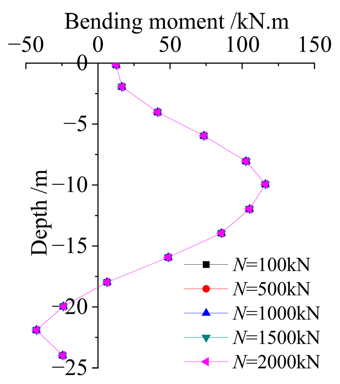
4.3.1. Effect of Vertical Load on Cap

Vertical loads of 100, 500, 1000, 1500, and 2000 kN were applied on the pile cap with a tunnel-cover depth of 12 m and a pile–tunnel distance of 7.5 m. Figure 10 shows the bending moment of the near pile under different vertical loads; positive values denote the tensile strain generated on the tunnel side. It can be seen from the results that the vertical load had little influence on the bending moment of the pile. The bending moment on the top of the near pile was 12 kN∙m; it increased to a maximum value of 115 kN∙m at the tunnel axis. Below the tunnel axis, the bending moment decreased to 0 at a depth of about 18 m and then decreased to a negative value below this depth. Therefore, the soil below 18 m (1 D below the tunnel axis) constrained the pile displacement toward the tunnel side and had a resistant effect on the adjacent pile.

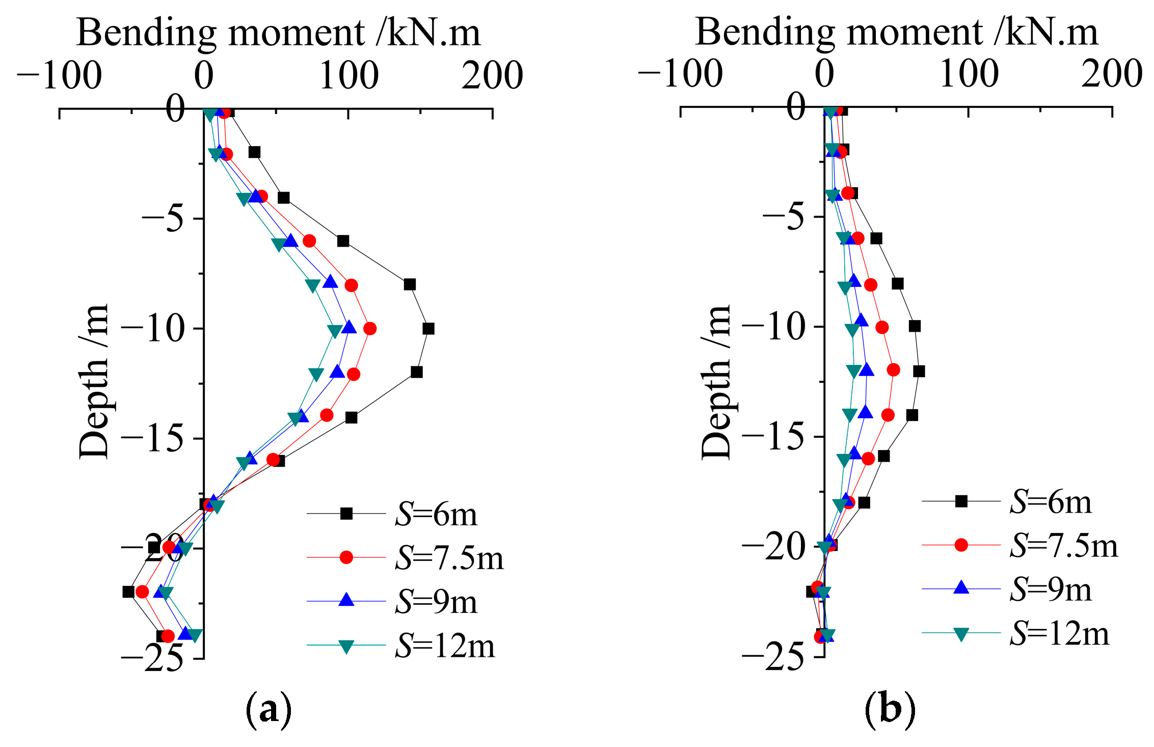
4.3.2. Effect of Pile–Tunnel Distance

Pile–tunnel distances of 6, 7.5, 9, and 12 m were studied with a tunnel-cover depth of 12 m and a vertical load of 500 kN. The influence of the pile–tunnel distance on the bending moment of the pile is shown in Figure 11. It can be seen from the results that the bending moment on the pile had similar distribution patterns at different pile–tunnel distances. The bending moment was small at the pile top and increased to its maximum value at the tunnel axis; below this value, it decreased to zero at depths of 18–20 m and then turned negative below 18–20 m; therefore, the deep soil had a resistant effect on the adjacent pile.
The influence of the pile–tunnel distance on the maximum bending moment of the pile is illustrated in Figure 12. It can be seen that when the pile–tunnel distance ranged between 6 m and 9 m (1–1.5 D), the maximum bending moment decreased significantly with the increase in the pile–tunnel distance. When the pile–tunnel distance was larger than 9 m (1.5 D), the change in the maximum bending moment on the pile was small, indicating that the main influence area on the pile bending moment was within 1.5 times that of the tunnel diameter. The maximum bending moment on the near pile and the far pile were 155 kN∙m and 65 kN∙m, respectively; when the pile–tunnel distance was 6 m, the maximum bending moment was reduced by 58% on the far pile induced by the shading effect. When the pile–tunnel distance was 12 m, the maximum bending moment on the near pile and far pile were 91 kN∙m and 20 kN∙m, respectively, and the maximum bending moment on the far pile was reduced by 78%.

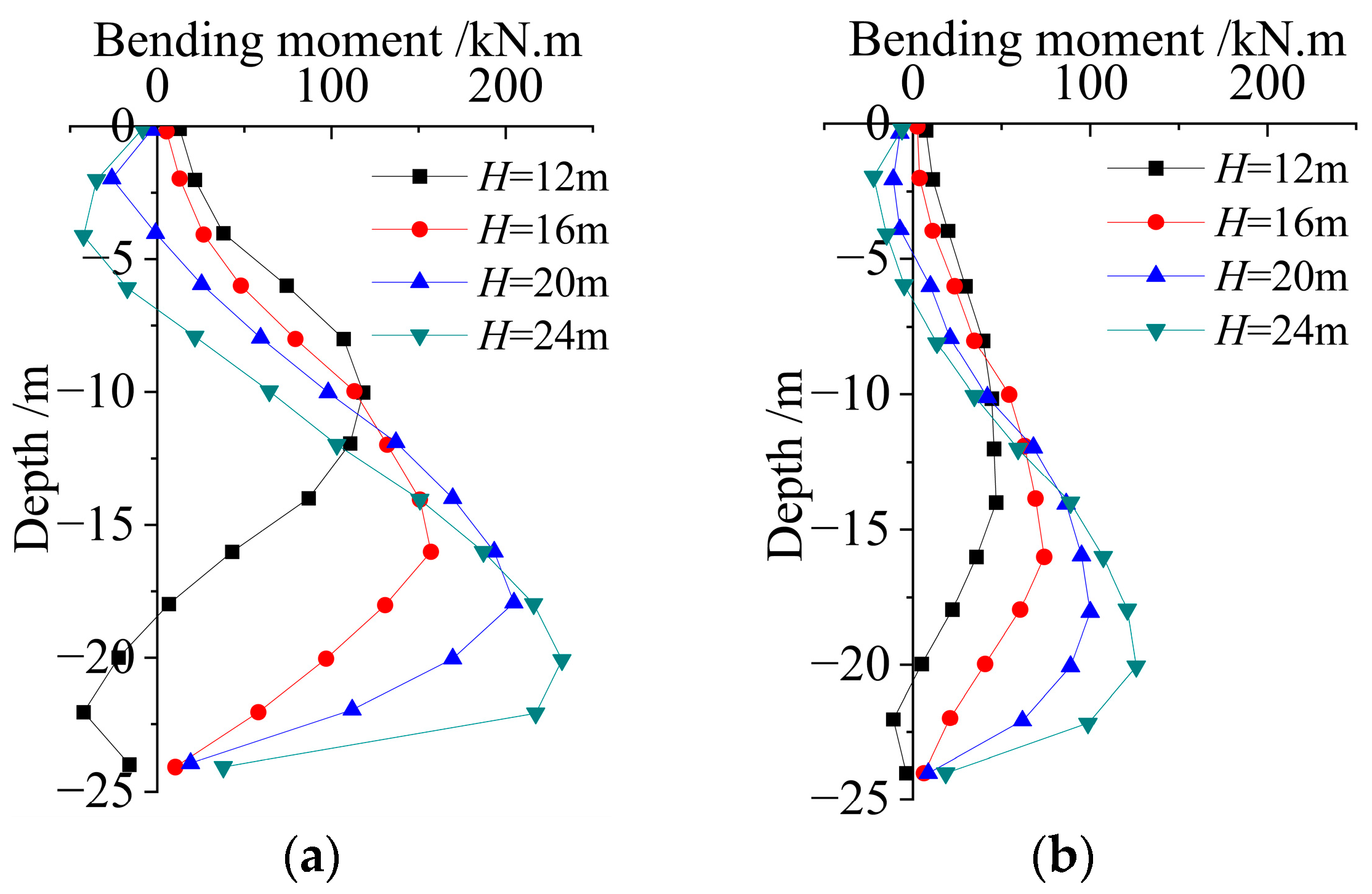
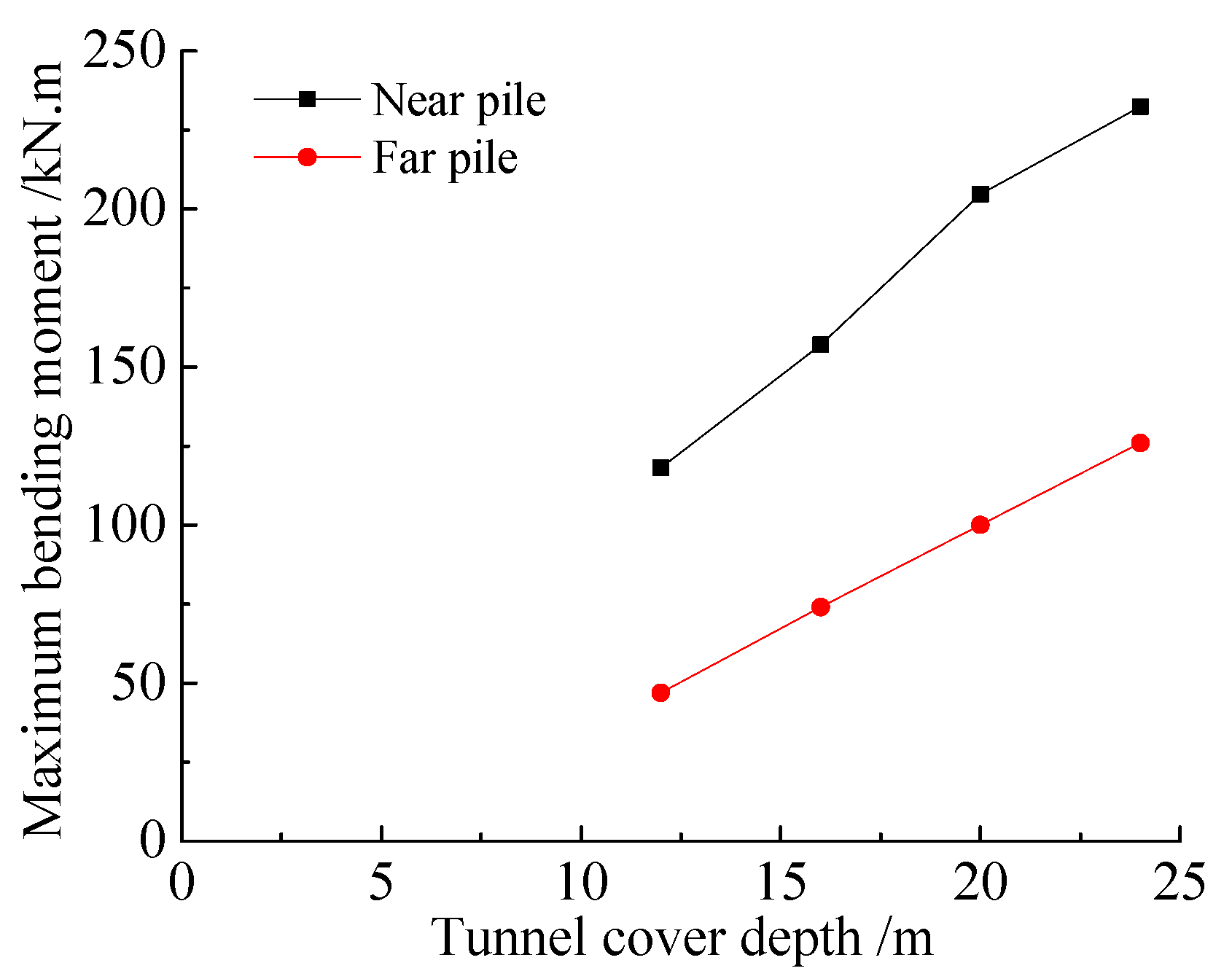
4.3.3. Effect of Tunnel-Cover Depth

Tunnel-cover depths of 12, 16, 20, and 24 m were investigated under conditions in which the pile–tunnel distance was 7.5 m and the vertical load on the cap was 500 kN. The influence of the tunnel-cover depth on the bending moment is shown in Figure 13. It can be seen from the results that the tunnel-cover depth had a strong influence on the distribution pattern of the pile bending moment; when tunnel-cover depth was 12 m, the bending moment on the upper part of the pile was positive, and it became negative below 18 m. As the tunnel-cover depth increased to 16 m, a positive bending moment was generated along the entire length of the pile; as the tunnel-cover depth increased to 20–24 m, a negative bending moment was generated on the upper part of the pile, while positive values were generated on the lower part of the pile. The maximum positive bending moment generated by the horizontal displacement of the pile was generally located at the tunnel axis. The maximum value increased with the increase in tunnel-cover depth, and the position of the maximum value moved downward simultaneously. A negative bending moment was caused by the soil far from the tunnel axis, which resisted the pile’s movement towards the tunnel. The bending moment of the far pile was much smaller than that of the near pile due to the shading effect.
Figure 14 shows the influence of the tunnel-cover depth on the maximum bending moment of the pile. It can be seen from the results that the maximum bending moment on the near pile and far pile increased roughly linearly with the tunnel-cover depth. When the tunnel-cover depth was 12 m, the maximum bending moments of the near pile and far pile were 112 and 49 kN∙m, respectively; the bending moment on the far pile was reduced by 56% due to the shading effect induced by the near pile. As the tunnel-cover depth increased to 24 m, the maximum bending moments on the near pile and far pile were 224 and 123 kN∙m, respectively; the bending moment on the far pile was reduced by 45%.

5. Conclusions

This paper studied the problem of shield-tunnel construction laterally passing through a pile foundation using an in situ test and a numerical method. The effect of the vertical load on the cap, pile–tunnel distance, and tunnel-cover depth, and, consequently, the effects of these factors on the horizontal displacement and bending moment of the adjacent pile were investigated, and the main conclusions are as follows.
(1) The results of the in situ tests of the displacement and bending moment matched the numerical results well. The shield construction induced adjacent pile displacement toward the tunnel side. The maximum values of the horizontal displacement and bending moment were at the tunnel axis. The positive bending moment generated around the tunnel axis (i.e., tensile on tunnel side), the negative bending moment generated on the pile far from the tunnel axis (i.e., compress on tunnel side), and the soil far from the tunnel axis had resistant effects on the pile, which constrained the pile’s displacement toward the tunnel side. Furthermore, the vertical load on the cap had little influence on the horizontal displacement and bending moment of the adjacent pile.
(2) The horizontal displacement and bending moment on the pile had similar distribution patterns at different pile–tunnel distances. As the pile–tunnel distance increased from 6 m to 12 m, the maximum horizontal displacement on the near pile decreased from 8.1 mm to 5.9 mm, and the maximum bending moment decreased from 155 kN∙m to 90 kN∙m. The main influence induced by the shield construction on the adjacent pile was located within an area 1.5 times greater than the tunnel diameter around the pile. The horizontal displacement and bending moment of the far pile were significantly reduced due to the shading effect induced by the near pile. When the pile–tunnel distance was 6 m, the maximum horizontal displacement of the far pile was reduced by 41%, and the maximum bending moment was reduced by 58%, compared with the near pile. As the pile–tunnel distance increased to 12 m, the maximum horizontal displacement of the far pile was reduced by 36%, and the maximum bending moment was reduced by 78%.
(3) The tunnel-cover depth had a significant influence on the distribution pattern of the horizontal displacement and bending moment on the pile. The positions of the peak values of the horizontal displacement and bending moment moved downward with increases in the tunnel-cover depth. When the tunnel-cover depth was 12 m, the positive bending moment generated on the upper part of the pile reached a negative value below 18 m. As the tunnel-cover depth increased to 16 m, a positive bending moment was generated along the entire length of the pile, and as the tunnel-cover depth increased to 20–24 m, a negative bending moment was generated on the upper part of the pile, while a positive value was generated on the lower part of the pile. The maximum horizontal displacement and bending moment increased with increases in the tunnel depth, the maximum horizontal displacement on the near pile increased from 6.8 mm to 11.1 mm, and the maximum bending moment on the near pile increased from 112 kN∙m to 224 kN∙m as the tunnel-cover depth increased from 12 m to 24 m.

Author Contributions

Conceptualization, S.Z. and X.N.; methodology, M.J.; software, S.W.; validation, S.Z., X.Z. and S.W.; formal analysis, S.W.; investigation, X.Z.; writing—original draft preparation, S.Z., S.W. and X.X.; writing—review and editing, M.J.; visualization, X.Z.; supervision, M.J.; project administration, X.Z. and H.L.; funding acquisition, X.N. All authors have read and agreed to the published version of the manuscript.

Funding

This research was funded by the National Natural Science Foundation of China (grant number: 51408197), Henan Key Laboratory of Grain and Oil Storage Facility & Safety, HAUT, Zhengzhou, 450001, China (grant number: 2021KF-B03), and the Key Project of Science and Technology Research of Henan Education Department (grant number: 23B560002).

Data Availability Statement

Not applicable.

Conflicts of Interest

The authors declare no conflict of interest.

References

  1. Sagaseta, C. Analysis of undrained soil deformation due to ground loss. Geotechnique 1987, 37, 301–320. [Google Scholar] [CrossRef]
  2. Park, K.H. Elastic solution for tunneling-induced ground movements in clays. Int. J. Geomech. 2004, 4, 310–318. [Google Scholar] [CrossRef]
  3. Pinto, F.; Whittle, A.J. Ground movements due to shallow tunnels in soft ground. I: Analytical solutions. J. Geotech. Geoenviron. 2013, 140, 04013040. [Google Scholar] [CrossRef]
  4. Loganathan, N.; Poulos, H.G. Analytical prediction for tunneling-induced ground movements in clays. J. Geotech. Geoenviron. 1998, 124, 846–856. [Google Scholar] [CrossRef]
  5. Loganathan, N.; Poulos, H.G.; Xu, K.J. Ground and pile-group response due to tunneling. Soils Found. 2001, 41, 57–67. [Google Scholar] [CrossRef]
  6. Chen, L.; Poulos, H.G.; Loganathan, N. Pile responses caused by tunneling. J. Geotech. Geoenviron. 1999, 125, 207–215. [Google Scholar] [CrossRef]
  7. Huang, M.; Zhang, C.; Li, Z. A simplified analysis method for the influence of tunneling on grouped piles. Tunn. Undergr. Space Technol. 2009, 24, 410–422. [Google Scholar] [CrossRef]
  8. Zhang, R.J.; Zheng, J.J.; Zhang, L.M. An analysis method for the influence of tunneling on adjacent loaded pile groups with rigid elevated caps. Int. J. Numer. Anal. Meth. Geomech. 2011, 35, 1949–1971. [Google Scholar] [CrossRef]
  9. Cheng, K.; Xia, T.; Liang, R. Vertical response analysis of adjacent existing single pile under tunneling. Chin. J. Geotech. Eng. 2018, 40, 42–46. [Google Scholar]
  10. Zhang, Z.G.; Huang, M.S.; Xu, C. Simplified solution for tunnel-soil-pile interaction in Pasternak’s foundation model. Tunn. Undergr. Space Technol. 2018, 78, 146–158. [Google Scholar] [CrossRef]
  11. Franza, A.; Zheng, C.; Marshall, A.M.; Jimenez, R. Investigation of soil–pile–structure interaction induced by vertical loads and tunneling. Comput. Geotech. 2021, 139, 104386. [Google Scholar] [CrossRef]
  12. Liu, B.; Yu, Z.; Yao, B.; Han, Y.; Liu, H.; Wang, S. Responses of the ground and adjacent pile to excavation of U-shaped tunnel. Comput. Geotech. 2021, 130, 103919. [Google Scholar] [CrossRef]
  13. Chen, X.; Zhang, X.; Zhou, X.; Ou, X.; Liu, J.; Liu, H.; Yu, W. Vertical mechanical response of axial loaded pile to tunneling-induced pile exposure. Comput. Geotech. 2023, 159, 105416. [Google Scholar] [CrossRef]
  14. Loganathan, N.; Poulos, H.G.; Stewart, D.P. Centrifuge model testing of tunnelling-induced ground and pile deformations. Geotechnique 2000, 50, 283–294. [Google Scholar] [CrossRef]
  15. Jacobsz, S.W.; Standing, J.R.; Mair, R. Centrifuge modelling of tunneling near driven piles. Soils Found. 2004, 44, 49–56. [Google Scholar] [CrossRef]
  16. Lee, Y.J.; Richard, H.B. Influence zones for 2D pile-soil-tunnelling interaction based on model test and numerical analysis. Tunn. Undergr. Space Technol. 2007, 22, 325–342. [Google Scholar] [CrossRef]
  17. Chiang, K.H.; Lee, C.J. Responses of single piles to tunneling-induced soil movements in sandy ground. Can. Geotech. J. 2007, 44, 1224–1241. [Google Scholar] [CrossRef]
  18. Ng, C.W.W.; Lu, H.; Peng, S.Y. Three-dimensional centrifuge modelling of the effects of twin tunneling on an existing pile. Tunn. Undergr. Space Technol. 2013, 35, 189–199. [Google Scholar] [CrossRef]
  19. Ng, C.W.W.; Lu, H. Effects of the construction sequence of twin tunnels at different depths on an existing pile. Can. Geotech. J. 2014, 51, 173–183. [Google Scholar] [CrossRef]
  20. Lu, H.; Shi, J.; Ng, C.W.W.; Lv, Y. Three-dimensional centrifuge modeling of the influence of side-by-side twin tunneling on a piled raft. Tunn. Undergr. Space Technol. 2020, 103, 103486. [Google Scholar] [CrossRef]
  21. He, S.; Lai, J.; Li, Y.; Wang, K.; Wang, L.; Zhang, W. Pile group response induced by adjacent shield tunnelling in clay: Scale model test and numerical simulation. Tunn. Undergr. Space Technol. 2022, 120, 104039. [Google Scholar] [CrossRef]
  22. Mroueh, H.; Shahour, I. Three-dimensional finite element analysis of the interaction between tunneling and pile foundations. Int. J. Numer. Anal. Meth. Geomech. 2002, 26, 217–230. [Google Scholar] [CrossRef]
  23. Lee, G.T.K.; Ng, C.W.W. Effects of advancing open face tunneling on an existing loaded pile. J. Geotech. Geoenviron. 2005, 132, 193–201. [Google Scholar] [CrossRef]
  24. Liu, C.; Zhang, Z.X.; Regueiro, R.A. Pile and pile group response to tunnelling using a large diameter slurry shield—Case study in Shanghai. Comput. Geotech. 2014, 59, 21–43. [Google Scholar] [CrossRef]
  25. Soomro, M.A.; Hong, Y.; Ng, C.W.W. Load transfer mechanism in pile group due to single tunnel advancement in stiff clay. Tunn. Undergr. Space Technol. 2015, 45, 63–72. [Google Scholar] [CrossRef]
  26. Cheng, C.Y.; Dasari, G.R.; Chow, Y.K. Finite element analysis of tunnel-soil-pile interaction using displacement controlled model. Tunn. Undergr. Space Technol. 2007, 22, 450–466. [Google Scholar] [CrossRef]
  27. Xu, K.J.; Poulos, H.G. 3-D elastic analysis of vertical piles subjected to “passive” loadings. Comput. Geotech. 2001, 28, 349–375. [Google Scholar] [CrossRef]
  28. Kitiyodom, P.; Matsumoto, T.; Kawaguchi, K. A simplified analysis method for piled raft foundations subjected to ground movements induced by tunneling. Int. J. Numer. Anal. Meth. Geomech. 2005, 29, 1485–1507. [Google Scholar] [CrossRef]
  29. Soomro, M.A.; Kumar, M.; Xiong, H.; Mangnejo, D.A.; Mangi, N. Investigation of effects of different construction sequences on settlement and load transfer mechanism of single pile due to twin stacked tunneling. Tunn. Undergr. Space Technol. 2020, 96, 1032171. [Google Scholar] [CrossRef]
  30. Li, Y.; Zhang, W. Investigation on passive pile responses subject to adjacent tunnelling in anisotropic clay. Comput. Geotech. 2020, 127, 103782. [Google Scholar] [CrossRef]
  31. Li, H.; Liu, S.; Tong, L. A numerical interpretation of the soil-pile interaction for the pile adjacent to an excavation in clay. Tunn. Undergr. Space Technol. 2022, 121, 104344. [Google Scholar] [CrossRef]
  32. Gu, X.; Chen, F.; Zhang, W.; Wang, Q.; Liu, H. Numerical investigation of pile responses induced by adjacent tunnel excavation in spatially variable clays. Undergr. Space. 2022, 7, 911–927. [Google Scholar] [CrossRef]
  33. Zheng, G.; Wang, R.; Lei, H.; Zhang, T.; Fan, Q. Load-transfer-associated settlements of a piled building during shield tunnelling in soft ground. Tunn. Undergr. Space Technol. 2023, 133, 104964. [Google Scholar] [CrossRef]
  34. Sazid, M.; Ahmed, H.A. Stability analysis of shallow depth tunnel in weak rock mass: 3d numerical modeling approach. J. City Dev. 2019, 1, 18–22. [Google Scholar]
  35. Kainthola, A.; Singh, P.K.; Wasnik, A.B.; Sazid, M.; Singh, T.N. Finite element analysis of road cut slopes using hoek & brown failure criterion. Int. J. Earth Sci. Eng. 2012, 5, 1100–1109. [Google Scholar]
  36. Saharan, M.R.; Jha, B.K.; Sazid, M.; Kumar, R. Designing cut-out distance for continuous miners’ operations using numerical modelling and rock mechanics instrumentation. In Proceedings of the Workshop on Application of Rock Mechanics-Tools & Techniques, New Delhi, India, 1 January 2010. [Google Scholar]
  37. Zhang, Y.; Yin, Z.; Xu, Y. Analysis on three-dimensional ground surface deformations due to shield tunnel. Chin. J. Rock Mech. Eng. 2002, 21, 388–392. [Google Scholar]
  38. Franzius, J.N.; Potts, D.M. Influence of mesh geometry on three-dimensional finite-element analysis of tunnel excavation. Int. J. Geomech. 2005, 5, 256–266. [Google Scholar] [CrossRef]
  39. Mair, R.J.; Taylor, R.N.; Bracegirdle, A. Subsurface settlement profiles above tunnels in clays. Geotechnique 1993, 43, 315–320. [Google Scholar] [CrossRef]
  40. Guerola-Navarro, V.; Gil-Gomez, H.; Oltra-Badenes, R.; Soto-Acosta, P. Customer relationship management and its impact on entrepreneurial marketing: A literature review. Int. Entrep. Manag. J. 2022, 18, 256–266. [Google Scholar] [CrossRef]
  41. Jiao, Z.; Liu, Y. Calculation methods of bending moment in diaphragm wall tests. Chin. J. Geotech. Eng. 2006, 28, 1485–1488. [Google Scholar]
  42. Ooi, P.S.K.; Ramsey, T.L. Curvature and bending moments from inclinometer data. Int. J. Geomech. 2003, 3, 64–74. [Google Scholar] [CrossRef]
Figure 1. Schematic of tunnel adjacent to bridge piles.
Buildings 13 02455 g001
Figure 2. Numerical model of shield tunnel adjacent to pile foundation (pink is the pile, green is the cap, and multiple colors represent the different rings of the tunnel segments).
Buildings 13 02455 g002
Figure 3. In situ test of bridge-pile foundation. (a) Horizontal displacement. (b) Rebar stress.
Buildings 13 02455 g003
Figure 4. Comparison of measured and numerical results of pile foundation near the tunnel side (near pile). (a) Horizontal displacement. (b) Bending moment.
Buildings 13 02455 g004
Figure 5. Influence of vertical load on horizontal displacement of near pile.
Buildings 13 02455 g005
Figure 6. Influence of pile–tunnel distance on horizontal displacement of pile. (a) Near pile. (b) Far pile.
Buildings 13 02455 g006
Figure 7. Influence of pile–tunnel distance on maximum horizontal displacement of pile.
Buildings 13 02455 g007
Figure 8. Influence of tunnel-cover depth on horizontal displacement of pile. (a) Near pile. (b) Far pile.
Buildings 13 02455 g008
Figure 9. Influence of tunnel-cover depth on maximum horizontal displacement of the pile.
Buildings 13 02455 g009
Figure 10. Influence of the vertical load on bending moment of pile.
Buildings 13 02455 g010
Figure 11. Influence of pile–tunnel distance on bending moment of pile. (a) Near pile. (b) Far pile.
Buildings 13 02455 g011
Figure 12. Influence of pile–tunnel distance on maximum bending moment of pile.
Buildings 13 02455 g012
Figure 13. Influence of tunnel-cover depth on bending moment of pile. (a) Near pile. (b) Far pile.
Buildings 13 02455 g013
Figure 14. Influence of tunnel-cover depth on maximum bending moment of pile.
Buildings 13 02455 g014
Table 1. The physical and mechanical parameters of soil.
Soil TypeThickness of Soil
/m
Unit Weight
/kN∙m−3
Elastic Modulus
/MPa
Poisson’s RatioCohesion
/kPa
Internal Friction
Miscellaneous fill1.518.63.90.3195
Clayey silt36.519.27.20.2715.522.7
Silt2019.614.30.25326.2
Fine sand2719.918.80.23028
Disclaimer/Publisher’s Note: The statements, opinions and data contained in all publications are solely those of the individual author(s) and contributor(s) and not of MDPI and/or the editor(s). MDPI and/or the editor(s) disclaim responsibility for any injury to people or property resulting from any ideas, methods, instructions or products referred to in the content.

