Article

Study on the Effect of Radiant Insulation Panel in Cavity on the Thermal Performance of Broken-Bridge Aluminum Window Frame

1
College of Architecture and Environment, Sichuan University, Chengdu 610065, China
2
China Southwest Architecture Design and Research Institute Co., Ltd., Chengdu 610041, China
3
College of Architecture, Southwest Minzu University, Chengdu 610225, China
4
School of Building Services Science and Engineering, Xi’an University of Architecture and Technology, Xi’an 710055, China
5
College of Energy and Power Engineering, Xi’an Jiaotong University, Xi’an 710049, China
*
Author to whom correspondence should be addressed.
Buildings 2023, 13(1), 58; https://doi.org/10.3390/buildings13010058
Submission received: 6 December 2022 / Revised: 22 December 2022 / Accepted: 23 December 2022 / Published: 27 December 2022
(This article belongs to the Section Building Energy, Physics, Environment, and Systems)

Abstract

:
Windows have a great impact on building energy consumption, and the thermal performance of window frames directly affects its energy-saving potential. In this paper, a novel method is proposed to optimize the thermal performance of commercially available broken-bridge aluminum window frames, by incorporating radiant insulation panels (RIPs) into the window frame cavity. A typical aluminum alloy window frame heat transfer model is theoretically analyzed and validated, and the effects of key design parameters on the equivalent thermal conductivity (ETC) of the cavity radiation heat transfer and the heat transfer coefficient (U-factor) of window frames are quantitatively analyzed by a finite element simulation method using the THERM software. Moreover, the RIP, the insulation material filling, and low surface emissivity on the thermal performance of the window frame are compared and analyzed. The results show that the RIP is better placed in the middle, the width and quantity of RIPs are negatively correlated with the U-factor, while the surface emissivity of RIPs is positively correlated with the U-factor. Adding RIPs in the cavity can reduce the U-factor of the window frame by more than 7.43%, slightly lower than 8.97% for the filling type, but significantly higher than 0.81% for the low-emissivity type. Inserting RIPs is a simple and effective way to reduce the U-factor of the window frame and have a great potential of use.

1. Introduction

The building industry consumes 50% of the world’s electricity and accounts for 38% of the total global carbon emissions [1,2]. Normally, windows account for only a 1/8~1/6 portion of the building envelope area; however, its heat loss can reach about 40–50% of the total amount of the building envelope [3]. In recent years, the window-to-wall area ratio of buildings has gradually increased, owing to aesthetic ascension; thus, the improving of the thermal insulation performance of windows has been paid more attention [4].
The glass and window frame are the main parts of the window, and their thermal properties directly determine the energy-saving abilities of the whole window system. At present, with the continuous optimization of window glass, from single-layer glass to double-layer glass to the current new energy-saving glass, such as insulating glass, vacuum glass, color-changing glass [5], photovoltaic integrated glass [6], etc., the U-factor of glass is getting lower and lower, and has been as low as below 1 W/(m2·K), or even below 0.5 W/(m2·K). While the U-factor of traditional window frames is higher than 1.0 W/(m2·K), the U-factor of aluminum window frames is generally 1.4~2.8 W/(m2·K) [7]. Therefore, window frames have greater energy-saving potential.
The most used frame materials are PVC, wood, and aluminum [8]. The aluminum window frame is the more widely used among them due to its light weight, high safety, and good mechanical performance. However, the thermal conductivity of aluminum is large. Typically, putting a thermal break made of polyamide between an external and an internal aluminum profile is required to create some resistance to the heat transfer between the aluminum profiles [9]. This kind of window frame is called a broken-bridge aluminum window frame, and how to further reduce the U-factor of it has been a hot spot of research.
The heat transfer of window frames is mainly through the thermal conductivity of solids, and convective and radiative heat transfer in cavities [10]. The optimization of window frame geometry, material modification, and upgrading of molding technology can effectively improve the thermal performance of window frames [11,12,13]. Zajaset et al. [11] conducted a parametric study on window frame geometry and identified the factors that have the greatest impact on the thermal performance of window frames through sensitivity analysis: the optimal frame shape can reduce the U-factor to 0.71 W/(m2·K). Moreover, weakening the heat transfer inside the window frame cavity will be one of the directions for future window-frame improvement. Reducing the emissivity of its inner surface decreases the heat transfer in the cavity. Mao Huijun et al. [14] simulated the effect of the emissivity of the inner surface of the cavity on the thermal performance of the window frame; the results showed that, as the emissivity of the inner surface of the cavity decreases, the U-factor of the broken-bridge aluminum alloy window frame and the whole window decreases, and the descent ranges are 12.39% to 30.38%, and 2.72% to 9.69%, respectively. Paulos et al. [15] investigated the improvement of the thermal performance of 48 commercial high-performance aluminum, fiberglass, polyvinyl chloride (PVC), and wood composite window frames with aerogel-filled cavities by using a two-dimensional numerical simulation software; the result showed that filling the cavities of the window frames with aerogel can reduce the U-factor by 4% to 29%, and completely filling the cavities with aerogel can further reduce the U-factor by 35%. Agnieszka et al. [16] proposed a method to reduce the U-factor of PVC window frames without considering the change of frame geometry and material—filling the cavity with polyurethane foam and conducting two-dimensional numerical simulations of heat transfer. It was found that filling the cavity with polyurethane foam reduced the U-factor of the window frame by about 27%.
For broken-bridge aluminum window frames, the material has been determined and the thermal conductivity cannot be changed. The emissivity of the aluminum alloy is 0.2, which is already low enough among common materials, so it is difficult to reduce the emissivity of its inner surface. Filling the window frame cavities is an effective way, but with more materials consumed and the heavy mass, it is not energy-saving and environmentally friendly enough.
To solve the above problems, a method is proposed to reduce the U-factor of the cavity of the broken-bridge aluminum alloy window frame, by adding a thin layer of RIPs in the cavity, which can save material and have good thermal performance at the same time. In order to quantitatively analyze the influence of RIPs on the heat transfer of the window frame, this paper takes the commonly used broken-bridge aluminum alloy window on the market as the research object, simulates the influence of the properties of placement position, width, surface emissivity, and quantity of RIPs on the thermal performance of the window frame, and compares the thermal performance with that of filled and low-radiation window frames. This paper provides a new idea and solution for improving the thermal performance of window frames, which is important for further improving the thermal performance of windows and achieving the goal of energy saving and carbon neutrality.

2. Research Methodology

For the study of the thermal performance of windows, there are two main research methods: experimental testing and computer simulation. The common measurement methods for the U-factor include the heat flow meter method, the simple hot box-heat flow meter method, the thermometric method, and the quantitative infrared thermography method [17]. However, most of these measurements must satisfy the approximate steady-state heat-transfer conditions for large temperature differences and take at least 72 h in specific seasons [18]. Compared with experimental tests, computer simulation is more economical, repeatable, not limited by time and place, and are generally adopted by scholars. Numerical simulation has become an essential research method in the field of window heat transfer, such as THERM developed by Lawrence Berkeley National Laboratory (LBNL) in the United States, Flixo software by Informind Ltd. in Switzerland, Bisco by Physibel Laboratory in Belgium, and MQMC developed by Guangdong Academy of Construction Sciences in China. THERM is a finite element simulation software [19] with the advantages of being practical and efficient, with a rich library of materials. THERM is used by many scholars to study the thermal properties of window frames and studies show that the results of this software are accurate [20,21]. Gustavsen Arild et al. [22] carried out a 3D CFD simulation of natural convection in the internal cavity of a window frame. PVC and broken aluminum alloy window frames were selected for the study and the results showed that CFD is a good tool for analyzing the heat transfer in the internal cavity of a window frame, but THERM software is also a good choice when considering radiation and convection effects.
Figure 1 shows the research methodology adopted to achieve the study objectives. First, parameters such as dimensional information of the model and physical properties of the material were collected, and then the equivalent heat transfer coefficient of the model was calculated by mathematical equations. Then, the THERM software was used to perform the calculations, and the simulation results of the THERM software were verified with the mathematical calculations. After verifying that the THERM calculation results were correct, the THERM software was used in the subsequent study to simulate the effect law of RIP key design parameters on the U-factor of the window frame, and the difference between different methods of reducing the U-factor of the window frame was compared and analyzed.

2.1. Mathematical Model

Several codes define methods for experimental and numerical simulations of window frames, the most commonly used and accepted of which are ISO 15099 [23] and ISO 10077–2 [24]. The assumptions and calculations of the window frame model vary from code to code, but all consistently recommend the use of computer software simulations for calculations. Dariush et al [25]. used a two-dimensional heat transfer model to simulate the heat transfer inside a horizontal window frame and verified the correctness of ISO 15099 for heat conduction, convection, and simplified radiation models for window frame cavities.
The heat transfer inside the cavity includes radiation and convection heat transfer, and the insulation effect depends on the geometry of the cavity, its position (vertical, horizontal, inclined), the emissivity of the solid surface, and the thermophysical properties of the filling gas. To simplify the study, the concept of equivalent thermal conductivity is introduced in the calculation of heat transfer in the cavity of the window frame. If the heat transfer effect of an opaque material is assumed to be the same as that of a cavity, then the thermal conductivity of this opaque material is the ETC of the cavity. When calculating the ETC of a cavity, the radiation heat transfer and convection heat transfer of the cavity should both be considered. According to ISO 15099, the ETC of the cavity should be calculated according to the following equation [23]:
λ e q = ( h c + h r ) × d   ,
where
λeq is the equivalent thermal conductivity of the cavity, W/(m·K);
hc is the convective heat transfer coefficientof the air in the cavity, W/(m2·K), which shall be calculated based on the Nusselt number, and the Nusselt numbers of the three different cases shall be considered according to whether the heat flow direction is upward, downward or horizontal, respectively;
hr is the radiant heat transfer coefficient in closed cavity, W/(m2·K);
d is the width of the cavity in the direction of heat flow, m.

2.1.1. Convective Heat Transfer Coefficient

The hc should be calculated based on the Nusselt number, according to the following equation:
h c = N u λ a i d ,
where
Nu is Nusselt number;
λai is thermal conductivity of air, W/(m·K).
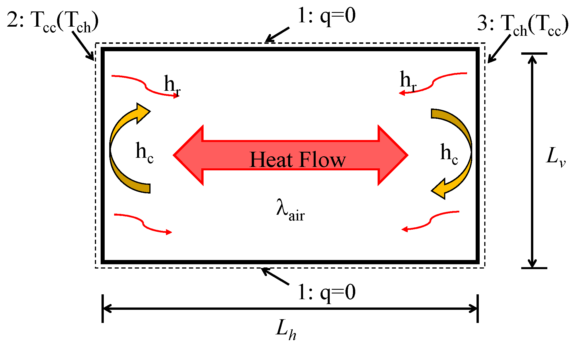
The Nusselt number is related to the aspect ratio of the cavity and the direction of heat flow. As shown in Figure 2, for a cavity with horizontal heat flow, the heat flow rate of surface 1 is equal to 0, and the temperatures of surface 2 and surface 3 are Tcc (or Tch) and Tch (or Tcc), respectively. The Nusselt number should be calculated as follows:
(a)
For Lv/Lh ≤ 0.5, the Nusselt number is:
u = 1 + { [ 2.756 × 10 6 R a 2 ( L v L h ) 8 ] 0.386 + [ 0.623 R a 1 / 5 ( L v L h ) 2 / 5 ] 0.386 } 2.59
N u = 1 + { [ 2.756 × 10 6 R a 2 ( L v L h ) 8 ] 0.386 + [ 0.623 R a 1 / 5 ( L v L h ) 2 / 5 ] 0.386 } 2.59
R a = ρ a i 2 L h 3 g c p , a i ( T c h T c c ) μ a i λ a i
where
ρai is the density of air, kg/m3;
Lh is the width of the cavity, m;
g is the acceleration of gravity, 9.8 m/s2;
cp,ai is the specific heat capacity of air at atmospheric pressure, J/(kg·K);
μai is the kinematic viscosity of air at atmospheric pressure, kg/(m·s);
Tch is the hot side temperature of air, K;
Tcc is the cold side temperature of air, K;
Ra is the Rayleigh number of the cavity.
  • (b) For Lv /Lh≥5, the Nusselt number is:
N u = m a x ( N u 1 , N u 2 , N u 3 )   ,
N u 1 = { 1 + ( 0.104 R a 0.293 [ 1 + ( 6310 R a ) 1.36 ] ) 3 } 1 / 3 ,
N u 2 = 0.242 ( R a L h L v ) 0.273 ,
N u 3 = 0.0605 R a 1 / 3  
  • (c) For 0.5 < Lv/Lh < 5, the Nusselt number is found using a linear interpolation between the endpoints of (a) and (b) above.
When air temperature is 10 °C, six different sets of aspect ratios are selected to show the relationship between width and hc of cavity in Figure 3. The hc of cavity is not a simple linear relationship with the width, but decreases first and then increases with the cavity width. When the cavity width is less than 0.027 m, the larger the aspect ratio is, the larger the hc is; while when the width is larger than 0.027 m, the larger the aspect ratio is, the smaller the hc is; and when the cavity width is 0.027 m, no matter what the aspect ratio is, the hc is equal to 2.77 W/(m2·K).

2.1.2. Radiant Heat Transfer

When the heat flow is in the horizontal direction, the hr of the cavity should be calculated according to the following equations:
h r = 4 σ T m 3 1 E + 1 F 1   ,
E = ( 1 ε 1 + 1 ε 2 1 ) 1  
F = 1 2 ( 1 + 1 + ( L h / L v ) 2 L h / L v )  
where
σ is Stephen–Boltzmann constant equal to 5.67 × 10⁻⁸ W/m2·K4;
ε1 and ε2 are the emissivities of surface 2 and surface 3, respectively.
When the air temperature is 10 °C and ε1 = ε2 = ε, the relationship between hr and aspect ratio of the cavity is shown in Figure 4. It can be seen from the figure that the larger the surface emissivity of the cavity and the smaller the aspect ratio, the smaller the hr.

2.1.3. Principle of RIP

Both lowering the surface emissivity or placing a RIP between the two surfaces can weaken the radiation heat transfer of the two surfaces. RIP is a thin plate with lower surface emissivity that is placed between radiating surfaces to weaken radiative heat transfer [26]. Adding the RIP can reduce the emissivity of the system, thereby reducing the radiation heat transfer. As shown in Figure 5a, a RIP is inserted between the parallel plates, and the surface temperatures of the two flat plates are T1 and T3 (T1 > T3). The radiation heat transfer without RIP is:
q 1 , 2 = σ ( T 1 4 T 2 4 ) 1 ε 1 + 1 ε 2 1   ,
Adding RIP3 between the plates increases the resistance to the radiation heat transfer process and reduces the amount of radiation heat transfer. At this time, the heat is not transferred directly from surface 1 directly to surface 2, but from surface 1 radiation first to the RIP plate 3, and then from the RIP plate 2 radiation to surface 2. When plate 3 is very thin, the thermal conductivity is relatively large. It can be considered that the temperature on both sides of plate 3 is equal for T3, and can get the surface 1,3 and surface 3,2 radiation heat transfer q1,3 and q3,2, respectively.
q 1 , 3 = σ ( T 1 4 T 3 4 ) 1 ε 1 + 1 ε 3 1   ,
q 3 , 2 = σ ( T 3 4 T 2 4 ) 1 ε 3 + 1 ε 2 1  
Under steady state heat transfer conditions, q1,3 = q3,2 = q’1,2. For ease of comparison, it can be assumed that the emissivity of each surface is equal, i.e., ε1 = ε2 = ε3 = ε. Therefore, it can be deduced from Equations (14) and (15):
T 3 4 = 1 2 ( T 1 4 T 2 4 )   ,
Substitute T3 into Equations (14) and (15) to get:
q 1 , 2 = 1 2 σ ( T 1 4 T 2 4 ) 1 ε 3 + 1 ε 2 1   ,
Comparing Equation (13) with Equation (17), it is found that the radiant heat transfer from the surface will be reduced to one-half of the original one after adding a RIP with the same emissivity as the surface. It can be inferred that the more the number of RIPs, the less the amount of radiative heat transfer. In fact, when a material with lower emissivity is chosen as the RIP, ε3 is much smaller than ε1 and ε2, and the thermal insulation effect is much more significant than the above analysis.
After adding the RIP, the ETC of the cavity as shown in Figure 4b should be calculated according to the following equation:
λ e q = L h L h l λ e q l + d λ + L h r λ e q r   ,
where
Lhl is the equivalent width of the left cavity, m;
d is the width of the RIP, m;
Lhr is the equivalent width of the right cavity, m.

2.2. Thermal Model

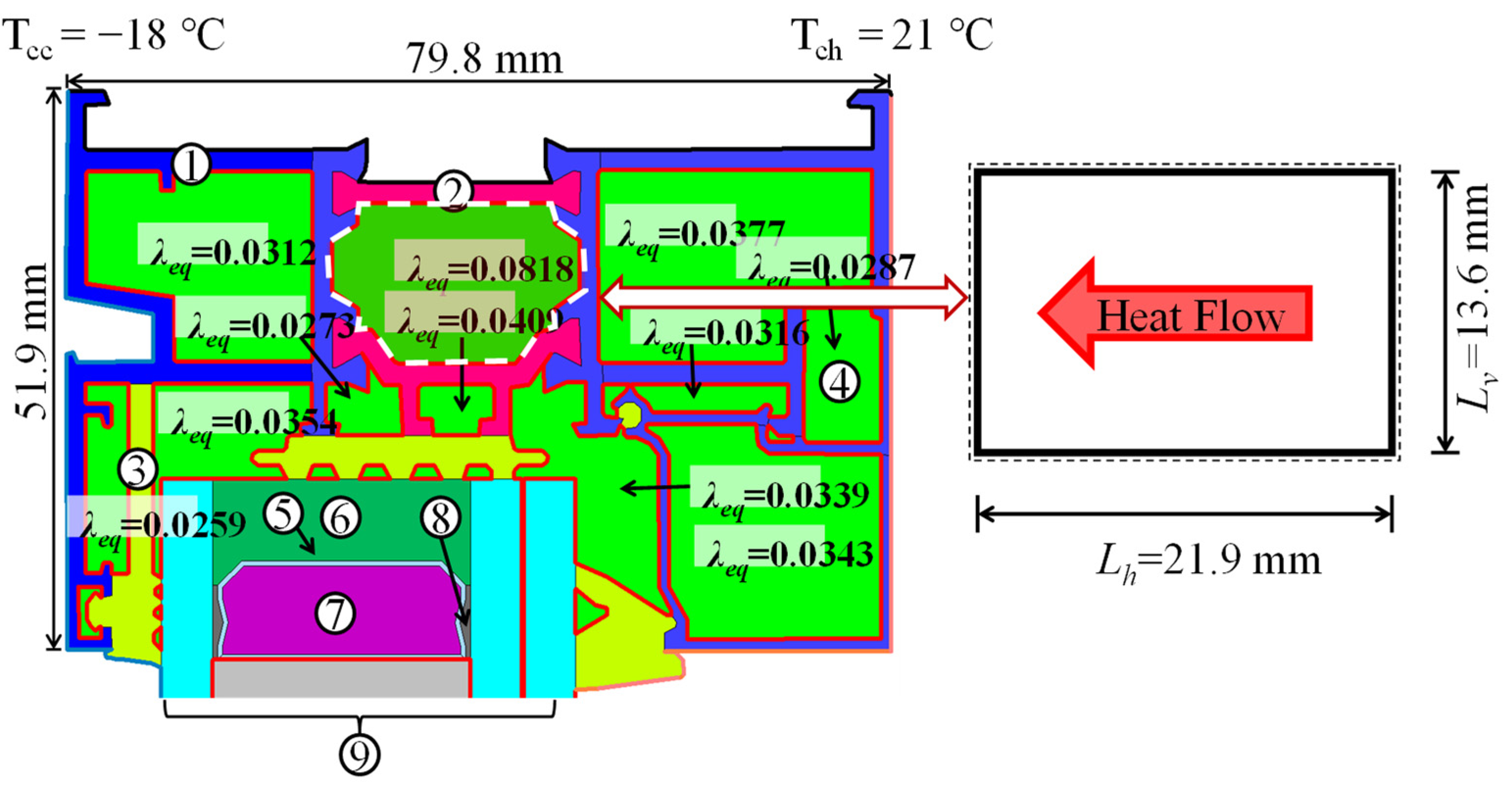
Aluminum window frames can be divided into 60, 70, 80, and other series according to their widths. The cross-sections of different series of window frames are different, and the cross-sections of the same series of window frames produced by different manufacturers also vary widely. Thus, it is not an easy task to investigate them in detail on a case-by-case basis. To simplify the study, as shown in Figure 6, a common commercially available 80 series aluminum window frame was used as the simulation object. This window frame uses triple sealing treatment on the cross section, so the sealing performance and heat insulation of the window frame itself is better in the same series. Therefore, if our method can have a good effect on reducing the U-factor of this kind of window frame, then the effect may be better for other window frames as well. This typical model of a broken-bridge aluminum window frame with a width of 51.9 mm and a thickness of 79.8 mm is established, and the material of each part of the frame and its thermal conductivity and surface emissivity are shown in Table 1. Usually, the shape of the cavity in the window frame is irregular and not easy to calculate, so the cavity is equated to a rectangle when calculating the ETC of the cavity, and the specific equivalence method is shown in the specification ISO 15099 [23]. The cavity in the dashed box can be equated to a rectangular cavity, with an equivalent width Lh of 21.9 mm and an equivalent height Lv of 13.6 mm. According to NFRC 100–2010 [27], the boundary conditions for simulation are shown in Table 2. In order to verify the correctness of the THERM software, the ETC of the cavity of the selected model was calculated using the mathematical equations mentioned in Section 2.1. The calculated results are shown in Figure 6 and are equal to the simulation results of THERM. The detailed calculation results of the heat transfer coefficient of the cavity closed by the broken bridge are shown in Appendix A. After verifying that the THERM calculation is accurate, the subsequent studies and calculations are done with the THERM.

3. Results

Firstly, the overall U-factor and the ETC of each cavity of a typical broken-bridge aluminum window frame are simulated and calculated: the U-factor of the window frame is 2.7575 W/(m2·k), and the ETC of each cavity is marked in Figure 6. As shown in Figure 6, the ETC of the cavity where the thermal break is located is the largest, 0.0818 W/m·K, which is the weakest link in the cavity of the window frame, and so the study is conducted for this cavity. The preliminary analysis shows that the U-factor of the cavity should be related to the position of the RIP, the width of the RIP, the number of RIPs, the surface emissivity of the RIP, etc. Therefore, the simulation analysis was conducted for these aspects.

3.1. Analysis of the Influence of the Main Design Parameters of RIP

3.1.1. Position of RIP

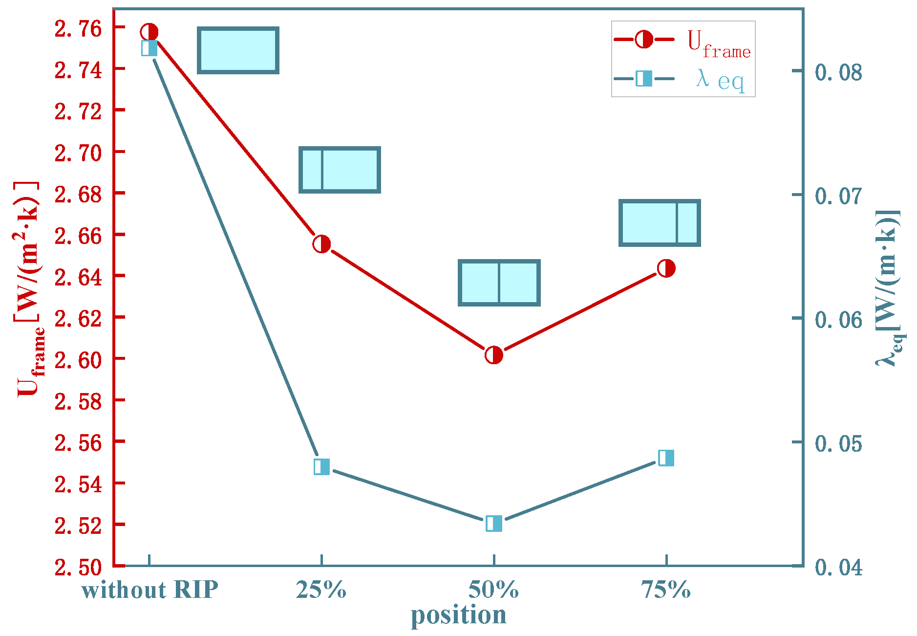
The width-to-height ratio of the cavity is different for different positions of the RIP, and the hc and hr are both related to the width-to-height ratio of the cavity. The width of the RIP is 1 mm, the material is polyamide (nylon), and the thermal conductivity is 0.25 W/m·K, and the surface emissivity is 0.9. The RIP is set at 25% Lh, 50% Lh, and 75% Lh from the left surface, and the simulation results are shown in Figure 7 and Table 3, where λeql is the ETC of the cavity on the left side of the RIP, and λeqr is the ETC of the right side of the RIP.
From Figure 7 and Table 3, the ETC of the cavity when the RIP is at 50% Lh is minimum 0.0434 W/(m2·k), and the overall U-factor of the window frame is minimum 2.6016 W/(m2·k). The ETC of the cavity decreased by 46.94% and the overall U-factor of the window frame decreased by 5.56% when the RIP was added at 50% Lh compared with the window frame without the RIP. The difference between the RIP at 25% Lh and 75% Lh on the heat transfer between the cavity and the frame is not significant, and this difference is most likely due to the error caused by the window frame modeling.

3.1.2. Width of RIP

The width of the RIP increases the thermal resistance of the RIP and reduces the width of the cavity on both sides of the RIP, and the effect on the heat transfer of the whole cavity is a multivariate coupling relationship. To investigate the effect law of the width of the RIP on the heat transfer of the window frame, the position of the RIP is set to be centered, and the width varies from 0.5 mm to 2.5 mm (interval of 0.5 mm), and the material is polyamide (nylon) with a surface emissivity of 0.9. The simulation results are shown in Figure 8 and Table 4.
As shown in Figure 8 and Table 4, the larger the width of the RIP, the larger the ETC of the cavity and the larger the U-factor of the window frame. The ETC of the cavity increased from 0.431 W/(m2·k) to 0.0444 W/(m2·k), an increase of 3.02%, and the U-factor of the window frame increased from 2.5980 W/(m2·k) to 2.6146 W/(m2·k), an increase of 0.64%, as the width of the RIP panel increased from 0.5 mm to 2.5 mm.

3.1.3. Surface Emissivity of RIP

From the above equations, it is known that the surface emissivity of the RIP mainly affects the radiation heat transfer in the cavity. The influence of the surface emissivity of the RIP on the heat transfer performance of the window frame is explored by setting the surface emissivity of the RIP to vary from 0.1 to 0.9 (interval of 0.1). The width of the RIP was 1 mm, 2 mm, and 3 mm, the material was polyamide (nylon), the surface emissivity was 0.9, and the position of the RIP was centered. The simulation results are shown in Figure 9.
As can be seen from Figure 9, for different widths of the RIP, the effect of the surface emissivity of the RIP on the U-factor of the window frame is similar, the surface emissivity of the RIP increases from 0.1 to 0.9, and the U-factor of the window frame with different widths of the RIP increases by about 0.06 W/(m2·k). As the surface emissivity of the RIP increases, the U-factor of the window frame increases, and the rate of increase gradually slows down. The surface emission of the RIP decreased from 0.9 to 0.1, a decrease of 2.11~2.20%.

3.1.4. Quantity of RIP

According to the principle of RIP, the more the number of RIPs, the smaller the hr will be, while the hc may increase, so in order to understand the effect of the number of RIPs on the U-factor of the window frame, we set the number of RIPs at 0~6, the width of the RIP is set to 1 mm, the spacing between the RIPs is 2 mm, the surface emissivity is 0.2, 0.5, and 0.9, respectively, and the material of the RIP is still polyamide (nylon). The simulation results are shown in Figure 10.
From Figure 10, it can be seen that for the RIPs with different surface emissivity, the effect of the number of RIPs on the U-factor of the window frame is similar: the more the number of RIPs, the smaller the U-factor of the window frame, but the rate of reduction slows down. The U-factor of the window frame decreases from 2.7575 W/(m2·k) to 2.5527 W/(m2·k) with the addition of one RIP with surface emissivity of 0.2, which decreases by 7.43%. Adding six RIPs with surface emissivity of 0.2 reduced the U-factor of the window frame by only 0.97% compared to one RIP.

3.2. Comparative Analysis of Methods to Reduce Heat Transfer in the Cavity

Filling with insulation is currently the main way of improve the thermal performance of the window frame cavity, and another way of improving the window frame cavity is to lower the emissivity of the inner surfaces. In order to compare the effect of cavity modification by adding RIP with these two methods, the effect of a different cavity filled with polyurethane and reducing the emissivity of the inner surface of different cavities on the thermal performance of window frames were simulated. As shown in the Table 5, window frame A is the control group, window frames B is the window frame filled with polyurethane, the cavities of the window frames filled with polyurethane are indicated in white, and the thermal conductivity of polyurethane is 0.024 W/m·k.

4. Discussions

Adding RIP to the cavity of the broken aluminum window frame can reduce the ETC of the cavity and then reduce the U-factor of the window frame. However, since there are three types of heat transfer in the cavity, namely conduction, convection and radiation, the heat transfer situation is complicated, and so the finite element simulation software is used to help the analysis. The simulation analysis shows that the placement, width, number, and surface emissivity of the RIP have an effect on the equivalent heat transfer coefficient of the cavity. Among them are:
  • The RIP placed in the middle of the cavity can reduce the U-factor of the window frame by 5.56%, which is more conducive to reducing the heat transfer of the window frame.
  • The wider the RIP, the greater the U-factor of the window frame, although the U-factor of the window frame increases 0.64% only while the width increases from 0.5 mm to 2.5 mm. The width of the RIP should be as small as possible considering the material cost and the weight of the window frame.
  • The smaller the surface emissivity of the RIP, the smaller the U-factor of the window frame. The surface emissivity of the RIP is reduced from 0.9 to 0.1, resulting in a reduction of 2.11%~2.20% of the U-factor. Therefore, the surface emissivity of RIP should be reduced as much as possible.
  • The more the amount of RIP, the smaller the U-factor of the window frame. However, increasing the amount of RIP does not have a significant impact on the reduction of the coefficient but increases the cost, while using one RIP can achieve the effect of reducing the U-factor of the window frame by 7.43%. Therefore, it is recommended to use one RIP.
  • Compared with the filling and low-emissivity window frames, the U-factor of the RIP type window frame is slightly higher than that of the filling type window frame, but significantly lower than that of the low-emissivity type window frame. The comparison of the RIP type window frame and low-emissivity type window frame shows that the RIP type window frame requires lower surface emissivity of material and functions better than the low-emissivity type window frame. At the same time, the RIP type window frame is less consumable and lighter than the filled type window frame, but the energy-saving effect is comparable to that of the filled type window frame. Filling type and low-emissivity type are more limited by the material, the heat transfer coefficient of the filled material should be lower than the equivalent heat transfer coefficient of the cavity in order to be useful, low-emissivity materials are often expensive, and ultra-low-emissivity materials still need more experimental studies, while RIP type can be made of common materials from a wide range of sources. In summary, the RIP type window frame is a better choice when considering the economy and energy-saving capability simultaneously.

5. Conclusions

Research has shown that RIP is a simple and effective method for reducing the U-factor of window frames. This method saves raw materials and the RIP window frame is simple to produce. The RIP window frame is highly cost-effective and has potential for commercial application. It is recommended that when producing the RIP window frame, since the RIP is fixed to the thermal break, the RIP should be the same material as the thermal break, such as the commonly used polyamide, so as to avoid the instability of bonding between different materials. The RIP should be placed in the middle of the window frame cavity, the RIP should be as thin as it can be, and the surface radiation coefficient of the RIP can be reduced appropriately when the conditions allow. This study has certain limitations, and subsequent studies should be conducted to experimentally test the practical application of RIP, optimize the calculation equation of cavity heat transfer, and quantify the energy-saving effect on buildings with this RIP window frame.

Author Contributions

Conceptualization, Y.Z. (Yanhong Zheng), Y.Z. (Yin Zhang) and P.S.; methodology, Y.Z. (Yanhong Zheng), Y.Z. (Yin Zhang) and P.S.; software, Y.Z. (Yanhong Zheng), D.H., and L.S.; validation, C.H. and L.S.; formal analysis Y.Z. (Yanhong Zheng), C.H. and L.S.; writing—original draft preparation, Y.Z. (Yanhong Zheng) and C.H.; writing—review and editing, Y.Z. (Yin Zhang); visualization, Z.J.; Resources, D.H. and Z.J.; supervision, Y.Z. (Yin Zhang). All authors have read and agreed to the published version of the manuscript.

Funding

This research received no external funding.

Data Availability Statement

The data presented in this study are available upon request from the corresponding author.

Conflicts of Interest

The authors declare no conflict of interest.

Appendix A

ParameterValueUnit
d0.02186m
hc2.71778W/(m2 × K)
Nu2.50000-
λai0.02377W/(m·K)
a0.00287-
b0.00008-
Lh0.02186m
Lv0.01360m
Lh/Lv1.60731-
Lv/Lh0.62216-
Nu(Lv/Lh = 0.5)2.85571-
Nu1(Lv/Lh = 5)2.09503-
Nu2(Lv/Lh = 5)2.69874-
Nu3(Lv/Lh = 5)1.96587-
Nu(Lv/Lh = 5)2.69874-
Ra34,308.39951-
ρai1.31015kg/m3
cp,ai1006.05501J/(kg·K)
a1002.73700-
b0.01232-
Tch6.65100°C
Tcc−14.48800°C
μai0.00002Pa·s
a0.00000-
b0.00000-
Tav−3.91850°C
g9.80000m/s2
β0.00371K−1
hr1.02439W/(m2·K)
εcc0.41000-
εch0.43000-
σ0.00000W/(m2·K4)
λeq0.08181W/(m·K)

References

  1. Wang, F.; Harindintwali, J.D.; Yuan, Z.; Chen, J.M. Technologies and Perspectives for Achieving Carbon Neutrality. Innovation 2021, 2, 100180. [Google Scholar] [CrossRef] [PubMed]
  2. Al-Sakkaf, A.; Bagchi, A.; Zayed, T. Evaluating Life-Cycle Energy Costs of Heritage Buildings. Buildings 2022, 12, 1271. [Google Scholar] [CrossRef]
  3. Yang, F.; Yang, B.; Guo, X.Z.; Yang, T.G. Energy-saving doors and windows and current technology research status. New Build. Mater. 2012, 1056, 84–89. [Google Scholar]
  4. Bienvenido-Huertas, D.; Oliveira, M.; Rubio-Bellido, C.; Marín, D. A Comparative Analysis of the International Regulation of Thermal Properties in Building Envelope. Sustainability 2019, 11, 5574. [Google Scholar] [CrossRef] [Green Version]
  5. Ke, Y.; Tan, Y.; Feng, C.; Chen, C.; Lu, Q.; Xu, Q.; Wang, T.; Liu, H.; Liu, X.; Peng, J.; et al. Tetra-Fish-Inspired Aesthetic Thermochromic Windows toward Energy-Saving Buildings. Appl. Energy 2022, 315, 119053. [Google Scholar] [CrossRef]
  6. Uddin, M.M.; Wang, C.; Zhang, C.; Ji, J. Investigating the Energy-Saving Performance of a CdTe-Based Semi-Transparent Photovoltaic Combined Hybrid Vacuum Glazing Window System. Energy 2022, 253, 124019. [Google Scholar] [CrossRef]
  7. Gustavsen, A.; Jelle, B.P.; Arasteh, D.; Kohler, C. State-of-the-Art Highly Insulating Window Frames—Research and Market Review; SINTEF: Trondheim, Norway, 2007; p. 941673. [Google Scholar]
  8. Saadatian, S.; Freire, F.; Simões, N. Embodied Impacts of Window Systems: A Comparative Assessment of Framing and Glazing Alternatives. J. Build. Eng. 2021, 35, 102042. [Google Scholar] [CrossRef]
  9. Lugaresi, F.; Kotsovinos, P.; Lenk, P.; Rein, G. Review of the Mechanical Failure of Non-Combustible Facade Systems in Fire. Constr. Build. Mater. 2022, 361, 129506. [Google Scholar] [CrossRef]
  10. Zajas, J.; Heiselberg, P. Analysis of energy saving potential and optimization of thermally broken fiberglass window frames. In Proceedings of the Building Simulation 2011 12th Conference of International Building Performance Simulation Association, Sydney, Australia, 14–16 November 2011; p. 8. [Google Scholar]
  11. Zajas, J.; Heiselberg, P. Parametric Study and Multi Objective Optimization of Window Frame Geometry. Build. Simul. 2014, 7, 579–593. [Google Scholar] [CrossRef]
  12. Appelfeld, D.; Hansen, C.S.; Svendsen, S. Development of a Slim Window Frame Made of Glass Fibre Reinforced Polyester. Energy Build. 2010, 42, 1918–1925. [Google Scholar] [CrossRef]
  13. Cardinale, N.; Rospi, G.; Cardinale, T. Numerical and Experimental Thermal Analysis for the Improvement of Various Types of Windows Frames and Rolling-Shutter Boxes. Int. J. Energy Environ. Eng. 2015, 6, 101–110. [Google Scholar] [CrossRef]
  14. Huijun, M.; Qinglin, M.; Shan, L.; Kai, W.; Peng, R. Influence of Cavities’Interior Surface Emissivity on Thermal Performance of Window Frame and Building Energy Consumption. J. Build. Energy Effic. 2022, 8, 31–37. [Google Scholar]
  15. Paulos, J.; Berardi, U. Optimizing the Thermal Performance of Window Frames through Aerogel-Enhancements. Appl. Energy 2020, 266, 114776. [Google Scholar] [CrossRef]
  16. Lechowska, A.A.; Schnotale, J.A.; Baldinelli, G. Window Frame Thermal Transmittance Improvements without Frame Geometry Variations: An Experimentally Validated CFD Analysis. Energy Build. 2017, 145, 188–199. [Google Scholar] [CrossRef]
  17. Bienvenido-Huertas, D.; Moyano, J.; Marín, D.; Fresco-Contreras, R. Review of in Situ Methods for Assessing the Thermal Transmittance of Walls. Renew. Sustain. Energy Rev. 2019, 102, 356–371. [Google Scholar] [CrossRef]
  18. Li, Y.; Teramoto, A.; Ohkubo, T.; Sugiyama, A. Estimation of Indoor Temperature Increments in Summers Using Heat-Flow Sensors to Assess the Impact of Roof Slab Insulation Methods. Sustainability 2022, 14, 15127. [Google Scholar] [CrossRef]
  19. Finlayson, E.; Mitchell, R.; Arasteh, D.; Huizenga, C.; Curcija, D. THERM 2.0: Program Description; Department of Energy: Wahington, DC, USA, 1998; p. 201. [Google Scholar]
  20. Blanusa, P.; Goss, W.P.; Roth, H.; Weitzmannn, P.; Jensen, C.F.; Svendsen, S.; Elmahdy, H. Comparison between ASHRAE and ISO Thermal Transmittance Calculation Methods. Energy Build. 2007, 39, 374–384. [Google Scholar] [CrossRef]
  21. Gustavsen, A.; Grynning, S.; Arasteh, D.; Jelle, B.P.; Goudey, H. Key Elements of and Material Performance Targets for Highly Insulating Window Frames. Energy Build. 2011, 43, 2583–2594. [Google Scholar] [CrossRef]
  22. Gustavsen, A.; Griffith, B.T.; Arasteh, D. Natural Convection Effects in Three-Dimensional Window Frames with Internal Cavities. Trans. Am. Soc. Heat. Refrig. Air Cond. Eng. 2001, 107, 527–537. [Google Scholar]
  23. ISO 15099-2003; Thermal Performance of Windows, Doors and Shading Devices: Detailed Calculations. International Organization for Standardization: Geneva, Switzerland, 2001.
  24. ISO 10077-2; Thermal Performance of Windows, Doors and Shutters–Calculation of Thermal Transmittance–Part 2: Numerical Method for Frames. International Organization for Standardization: Geneva, Switzerland, 2003.
  25. Gustavsen, A.; Arasteh, D.; Kohler, C.; Curcija, D. Two-Dimensional Conduction and CFD Simulations of Heat Transfer in Horizontal Window Frame Cavities. ASHRAE Trans. 2005, 111, 587–598. [Google Scholar]
  26. Zhang, X.; Ren, Z.; Mei, F. Heat Transfer; China Architecture & Building Press: Beijing, China, 2007. [Google Scholar]
  27. NFRC 100: 2010; Procedures for Determining Fenestration Product U-Factors. National Fenestration Rating Council: Greenbelt, MA, USA, 2010.
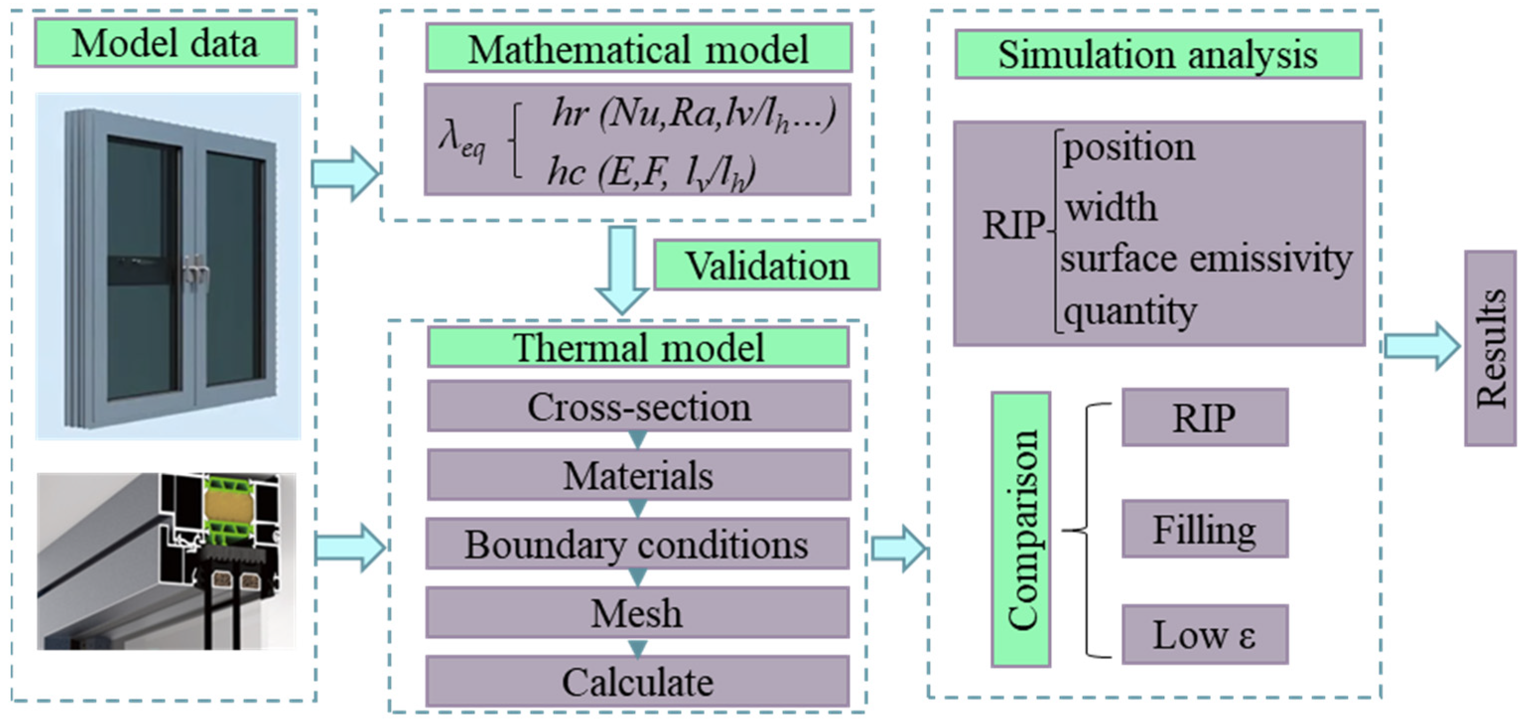
Figure 1. An outline of the research methodology.
Buildings 13 00058 g001
Figure 2. Schematic diagram of cavity heat transfer model.
Buildings 13 00058 g002
Figure 3. Relationship between cavity hc and width.
Buildings 13 00058 g003
Figure 4. Relationship between cavity hr and emissivity.
Buildings 13 00058 g004
Figure 5. (a): Schematic of RIP; (b): Model of the RIP.
Buildings 13 00058 g005
Figure 6. Typical thermal model of broken-bridge aluminum window frame.
Buildings 13 00058 g006
Figure 7. Effect of RIP position on heat transfer from window frame.
Buildings 13 00058 g007
Figure 8. Effect of RIP width on window frame.
Buildings 13 00058 g008
Figure 9. Effect of surface emissivity of RIP on U-factor of window frame.
Buildings 13 00058 g009
Figure 10. Effect of the number of RIP on the U-factor of the window frame.
Buildings 13 00058 g010
Table 1. Window frame materials.
NameMaterialThermal Conductivity [W/m·k]Surface Emissivity
Window FrameAluminum alloy1600.2
Thermal BreakPolyamide (Nylon)0.250.9
Sealing StripEPDM (Ternary ethylene propylene)0.250.9
CavityAir--
-Stainless Steel170.8
Sealing StripFlexible PVC0.140.9
DesiccantSilicone0.030.9
SealantSolid/hot melt isobutylene0.240.9
Glass Systems---
Table 2. NFRC simulation condition.
ParameterValue
ToutExterior ambient temperature of −18 °C
TinInterior ambient temperature of 21 °C
VWind speed of 5.5 m/s
Trm,outMean exterior radiation temperature of Tout
Trm,inMean interior radiation temperature of Tin
hcv,outExterior surface coefficient of heat transfer of 26 W/m2 °C
hcv,inInterior surface coefficient of heat transfer of 3.29 W/m2 °C
IsTotal density of heat flow rate of incident solar radiation of 0 W/m2
Table 3. Effect of RIP position on heat transfer from window frame.
PositionBuildings 13 00058 i001Buildings 13 00058 i002Buildings 13 00058 i003Buildings 13 00058 i004
λeql/λeqr [W/(m·k)]-0.0314/0.05560.0418/0.04160.0566/0.0335
λ′eq [W/(m·k)]0.08180.04800.04340.0487
Uframe [W/(m2·k)]2.75752.65522.60162.6435
Table 4. Effect of RIP width on heat transfer from window frames.
Width(mm)0.51.01.52.02.5
λeqleqr
[W/(m·k)]
0.0412/0.04310.0407/0.04260.0403/0.04210.0396/0.04160.0391/0.041
λ′eq
[W/(m·k)]
0.04310.04340.04380.04410.0444
Uframe
[W/(m2·k)]
2.59802.60132.60512.60992.6146
Table 5. Comparative analysis of methods for reducing heat transfer in the cavity.
ConditionCavity TypeInner EmissivityUframeRelative Error
A-0.22.7575-
BPolyurethane foam filling-2.5102−8.97%
CLow radiation surface0.12.7425−0.54%
DUltra low radiation surface0.052.7351−0.81%
Disclaimer/Publisher’s Note: The statements, opinions and data contained in all publications are solely those of the individual author(s) and contributor(s) and not of MDPI and/or the editor(s). MDPI and/or the editor(s) disclaim responsibility for any injury to people or property resulting from any ideas, methods, instructions or products referred to in the content.