Abstract
Freeze–thaw damage is one of the primary causes deteriorating the seismic resistance of reinforced concrete (RC) structures. This paper proposed a freeze–thaw damage deterioration model for C30 concrete, and it can be employed to study the time-varying seismic performance of aging RC columns. Next, this study developed a seismic fragility analysis framework for deteriorating RC columns considering the effect of freeze–thaw damage. Considering the geometric parameters of the case-study bridge, the deterioration characteristics of material, and the uncertainties involved in structural modeling and ground motions, a probabilistic seismic fragility analysis on aging RC columns was conducted. The results indicate that the influence of freeze–thaw damage cannot be ignored in studying the seismic performance of aging RC structures. The seismic fragilities of deteriorating RC columns shown a nonlinear increase trend as the increased of freeze–thaw cycles and severity of the damage state. In the early stage of freeze–thaw cycles, the seismic fragilities of RC columns increased slowly. However, the closer to the later stage of freeze–thaw cycles, the more significant of the increase in the seismic fragilities of the columns.
1. Introduction
Effect of freeze–thaw damage on the seismic behavior of RC structures has attracted an increasing attention. In the northern coastal regions of China, there are numerous cross-sea bridges with RC structures. These regions have long and cold winters, with average temperature below minus 6 degrees, relatively heavy snowfall, and deep snow. Therefore, these bridges are prone to freeze–thaw cycles, which greatly aggravates the damage to RC piers in seawater [1]. A large amount of seismic damage data [2,3,4] shows that the structures after freeze–thaw damage are more prone to damage from the earthquake excitations, which seriously affects their long-term performance and safe operations. Therefore, it is of great importance to explore the deterioration law of the seismic performances of RC structures subjected to freeze–thaw cycling in the northern coastal regions.
Numerous scholars have conducted many studies regarding the reduction in the mechanical properties of concrete and deterioration of the seismic behavior of structures under freeze–thaw cycles. For example, Yu et al. [5] recommended a concrete deterioration model through the rapid freeze–thaw tests. Si et al. [6] have experimentally and numerically investigated the freeze–thaw damage on the mechanical properties of concrete. In addition, Li et al. [7] studied the impacts of different air contents and water–cement ratios on concrete members through a series of freeze–thaw cycle tests. Xu et al. [8] proposed a bond stress–slip constitutive model of concrete in the marine environments through the freeze–thaw tests and numerical simulations. Moreover, Wang and Petru [9] studied the bonding properties of concrete after the rapid freeze–thaw cycles in the fresh and salt water through the pull-out tests, and they also established a simplified trilinear constitutive model. Gong et al. [10] explored the utilization of a multi-scale macroscopic mechanical damage simulation method regarding the performance of concrete via many freeze–thaw cycling and the silicic acid reaction tests.
Furthermore, Liu et al. [11] studied the seismic vulnerabilities of bridge piers and established a probabilistic seismic demand model through freeze–thaw tests and monitoring data. Yu et al. [12] modified the Drucker-Prager (DP) constitutive model and established a constitutive model for concrete via the freeze–thaw tests. Niu et al. [13] explored the variations in the compressive strength, flexural strength, and the relative dynamic elastic modulus of concrete through the extreme freeze–thaw tests. Although many scholars have experimentally explored the effect of freeze–thaw cycling process on the mechanical properties of concrete and seismic performance of RC structures [1,3,14,15,16,17], the constructed freeze–thaw deterioration models are only obtained through several given test results, which may have certain contingency limitations. In addition, dimensions of the specimens are different, and the testing methods are also varied. These factors would lead to the significant variations of the test results reported in the literature. Therefore, to establish a general freeze–thaw deterioration model is crucial, which is of great importance to the investigations on the seismic performance of deteriorating RC structures.
In this paper, a review of the test results of freeze–thaw damage to concrete by several previous researchers was conducted. Analyses regarding the variation laws of concrete constitutive parameters with different freeze–thaw cycles were performed. Combined with the traditional Mander model, a freeze–thaw damage deterioration model of C30 concrete was suggested, which could be used to investigate freeze–thaw cycling on the seismic performance of RC structures. Moreover, by incorporating both the uncertainties in ground motions and the structural-related parameters, this paper proposed a seismic fragility analysis framework for RC columns exposed to freeze–thaw damage, and the seismic fragility curves were developed.
2. The Proposed Deterioration Model of RC Columns
Freeze–thaw cycling could not only deteriorate the performance of concrete, but also affect the seismic resistance of RC columns. At present, the seismic investigations of RC columns are often carried out via nonlinear time history analysis (NTHA), which is often based on a nonlinear fiber-element model. When establishing the nonlinear finite element (FE) models, it is crucial to construct the constitutive models of the cover concrete, confined concrete, and steel bars, respectively. The test results in [1,18,19] indicated that freeze–thaw cycles have little effect on the mechanical properties of steel bars. Therefore, in this paper, freeze–thaw cycling on the material properties of concrete was mainly investigated, whereas that on the properties of steel bars was ignored.
For those bridges in the northern coastal regions, RC columns are generally located in the fluctuation zone of sea-water level, which is in direct contact with the seawater. Therefore, freeze–thaw cycles mainly affect RC columns and it usually has little impact on the bridge superstructure [20]. In addition, C30 concrete is generally used as the main material in the constructions of the columns of the cross-sea bridges in the northern coastal regions China. Therefore, this paper proposed a deterioration model for C30 concrete under different freeze–thaw cycles. This deterioration model includes the traditional Mander constitutive model of the plain and confined concrete. Finally, the established model is used to explore the deterioration effects on the constitutive properties of concrete caused by freeze–thaw damage on the probabilistic seismic demand and seismic capacity, and seismic fragility estimates of RC columns.
2.1. Review of the Experimental Data
In order to fully consider the influence of the uncertainties of raw materials, specimen size, test process, and other factors on the freeze–thaw test results, this paper selected the representative test results from [10,14,21,22,23] to establish the deterioration model of C30 concrete. The basic parameters of different specimens are given in Table 1.

Table 1.
The design parameters of the specimens.
As seen from Table 1, the freeze–thaw tests were mainly applied to plain concrete, while the freeze–thaw tests applied to RC specimens were relatively less. Meanwhile, there are some differences in the material parameters, specimen size, and test process used by different scholars, which would inevitably lead to the variations in the freeze–thaw test results. As a consequence, it is significant to study the variations of these test results in constructing a more accurate deterioration model for RC columns. Thus, the collected freeze–thaw test results were statistically analyzed and the variation rules of the key constitutive parameters of concrete under different freeze–thaw cycles were studied. Furthermore, combined with the traditional Mander model, the deterioration model was established, which provides a necessary time-varying constitutive model for the subsequent seismic fragility analysis of the bridge.
2.2. Freeze–Thaw Test Results of Plain Concrete
2.2.1. Variation Law of the Peak Stress
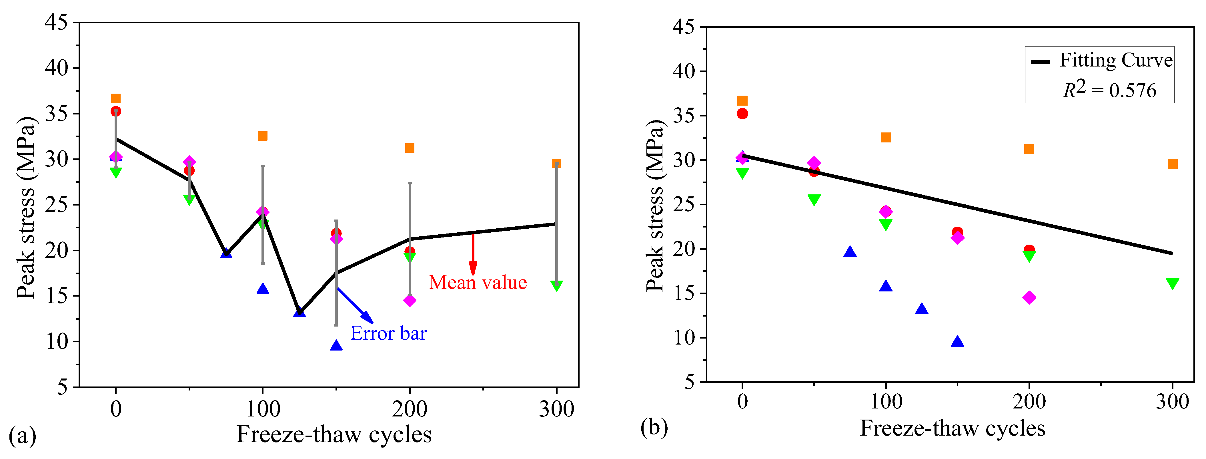
The statistical parameters and experimental data of the peak stress of plain concrete listed in Table 1 are drawn in Figure 1. As seen from Figure 1a, the peak stress exhibited an overall downward trend [6,24,25,26]. When freeze–thaw cycles reached 300, the mean value of the peak stress of C30 concrete decreased by 28.93%. Under different freeze cycles, the peak stress fluctuated greatly. For instance, in the early freeze–thaw cycling stages, the discrepancy was relatively small. However, the closer to the later stages of the freeze–thaw cycling, the greater the discrepancy. The range of the variation coefficient was between 0 and 0.33, indicating the strong discrepancy of the test results. Next, the peak stress parameters were fitted, which is shown in Figure 1b, and the compressive strength of plain concrete can be determined by,
where N is the number of the freeze–thaw cycles.
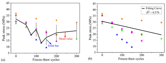
Figure 1.
The peak stress test results of C30 concrete: (a) the mean value and error results and (b) the fitting curve. (Note:  represents Gong et al. (2018) [10];
  represents Niu et al. (2019) [21];
  represents Duan et al. (2011) [22];
  represents Sun et al. (2019) [23]; and
  represents Zhang et al. (2019) [14]).
 represents Gong et al. (2018) [10];
  represents Niu et al. (2019) [21];
  represents Duan et al. (2011) [22];
  represents Sun et al. (2019) [23]; and
  represents Zhang et al. (2019) [14]).
2.2.2. Variation Law of the Peak Strain
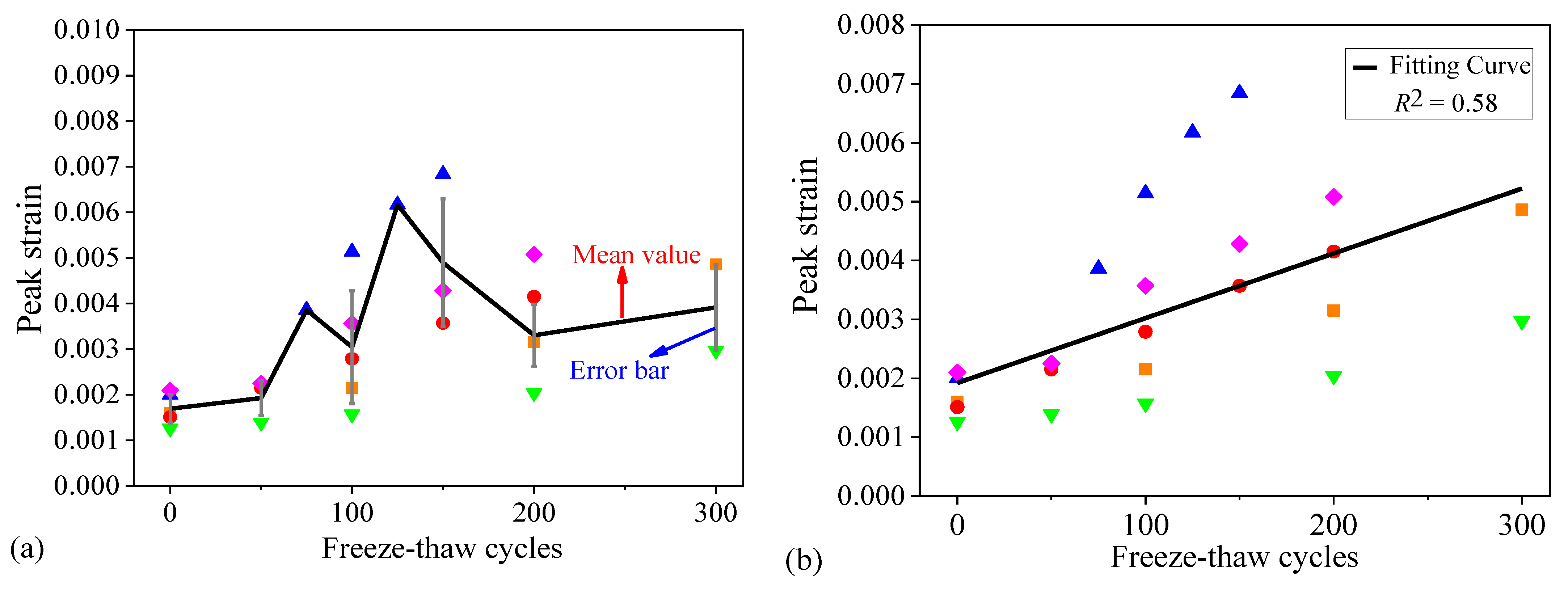
The statistical parameters and experimental data of the peak strain of plain concrete listed in Table 1 are drawn in Figure 2. As seen from Figure 2a, the peak strain of concrete exhibited an overall upward trend [10,27,28]. As freeze–thaw cycles reached 300, the mean value of the peak strain increased by 1.3 times. Under different freeze–thaw cycles, the peak strain fluctuated greatly. For example, in the early stage of freeze–thaw cycling, the discrepancy was relatively small. However, the discrepancy increased significantly in the middle time period. The variation coefficient range was between 0 and 0.41, suggesting the strong discrepancy of the test results. Similarly, the peak strain parameters were fitted, as shown in Figure 2b. The peak strain of plain concrete can be obtained by,
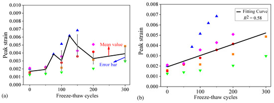
Figure 2.
The peak strain test results of C30 concrete: (a) the mean value and error results and (b) the fitting curve. (Note:  represents Gong et al. (2018) [10];
  represents Niu et al. (2019) [21];
  represents Duan et al. (2011) [22];
  represents Sun et al. (2019) [23]; and
  represents Zhang et al. (2019) [14]).
 represents Gong et al. (2018) [10];
  represents Niu et al. (2019) [21];
  represents Duan et al. (2011) [22];
  represents Sun et al. (2019) [23]; and
  represents Zhang et al. (2019) [14]).
2.2.3. Variation Law of the Elastic Modulus
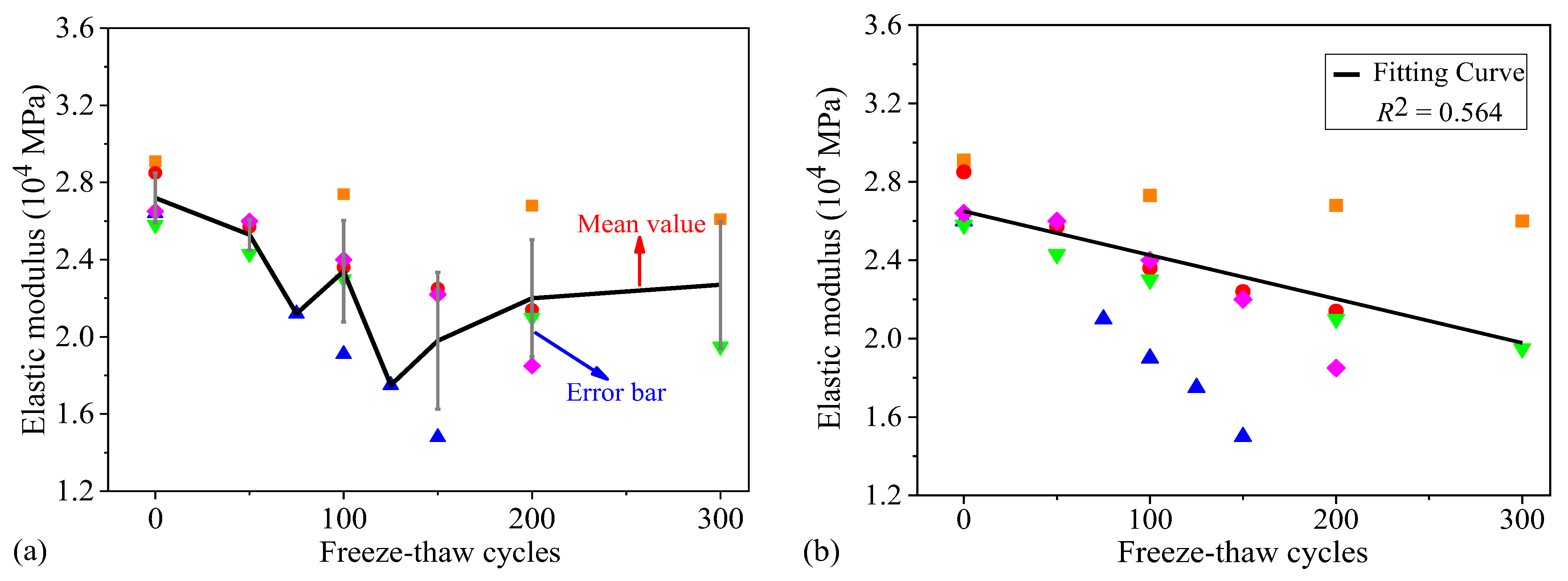
The statistical parameters and experimental data the elastic modulus of plain concrete listed in Table 1 are shown in Figure 3. As seen from Figure 3a, the elastic modulus of concrete also exhibited a global downward trend [26,29,30,31]. When freeze–thaw cycles reached 300, the mean value of the elastic modulus of concrete decreases by 16.54%. Under different freeze–thaw cycles, the discrepancy of the test results fluctuated greatly. In the early stages of freeze–thaw cycling, the discrepancy was relatively small. The closer the process to the later freeze–thaw period, the greater the discrepancy. After the calculation, the variation coefficient range of the elastic modulus was between 0 and 0.18. Next, the elastic modulus parameters are fitted, which is shown in Figure 3b. The elastic modulus of plain concrete can be acquired by,
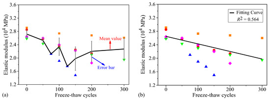
Figure 3.
Elastic modulus test results of C30 concrete: (a) the mean value and error results and (b) the fitting curve. (Note:  represents Gong et al. (2018) [10];
  represents Niu et al. (2019) [21];
  represents Duan et al. (2011) [22];
  represents Sun et al. (2019) [23]; and
  represents Zhang et al. (2019) [14]).
 represents Gong et al. (2018) [10];
  represents Niu et al. (2019) [21];
  represents Duan et al. (2011) [22];
  represents Sun et al. (2019) [23]; and
  represents Zhang et al. (2019) [14]).
By analyzing the available experimental data listed in Table 1, the time-varying formulas of plain concrete constitutive parameters were obtained, which lays a good foundation for the establishment of deterioration model and seismic vulnerability analyses of the columns.
2.3. Development of the Proposed Deterioration Model
Mander model is currently widely utilized in the seismic analysis of concrete columns [32]. It is not only applicable to circular members, but can also be well applied to rectangular ones. This model essentially considers the influences of the effective area of the confined concrete, volumetric ratio, spacing and yield strength of stirrups on the mechanical properties of the confined concrete. Many scholars compared their freeze–thaw test results with the traditional Mander model [25,32,33]. The results suggested that the traditional Mander model is consistent well with the test results. In addition, Mander model could also better reflect the stress-strain curve of the whole test process. Considering the practicability of Mander model, freeze–thaw cycles (N) is introduced to build a modified Mander model, as given in Equation (4).
where is the concrete stress; is the compressive strength of the confined concrete; is the shape parameter; and is the strain-related coefficient. These parameters can be determined by,
where is the compressive strength of plain concrete; is the effective confining stress of the transverse reinforcements to concrete; is the peak strain of the confined concrete; is the peak strain of plain concrete; is the concrete strain; is the elastic modulus; and is the secant modulus. The established deterioration model is based on the material tests. The constitutive model of plain concrete has been verified. However, there are few constitutive models for the confined concrete subjected to the freeze–thaw damage. Further experimental studies should be carried out in future.
2.3.1. Constitutive Model of Plain Concrete under Freeze–Thaw Cycling
The key parameters of Mander model of plain concrete mainly include the peak stress, peak strain, and shape parameters. The peak stress and peak strain as given in Equations (1) and (2) were obtained as introduced in Section 2.2. In addition, by combining Equations (1)–(3), we can obtain the shape parameter by
By substituting Equations (1), (2) and (10) into Equation (4), the time-varying Mander model of plain concrete could be obtained.
2.3.2. Constitutive Model of the Confined Concrete
- (1)
- Time-varying formula for the peak stress
Based on Equation (1) and the reinforcement information of the components, the peak stress of the confined concrete can be obtained by,
- (2)
- Time-varying formula for the peak strain
Based on Equations (1), (2) and (11), the peak strain of the confined concrete can be obtained by,
where k2 is the ratio of the peak stress of the confined concrete to that of plain concrete.
- (3)
- Time-varying equation for the shape parameter
Based on Equations (3), (6) and (7), the shape parameter of the confined concrete can be expressed as,
By substituting Equations (11)–(13) into Equation (4), the time-varying Mander model of the confined concrete could be obtained. Based on the proposed time-varying constitutive models of the plain and confined concrete, the deterioration model of RC columns could be obtained, which lays the foundation for the seismic fragility analysis of RC columns in the following subsections.
3. Seismic Fragility Theory
Many scholars have studied the seismic fragility of the as-built RC structures [20,34,35,36,37,38]. Seismic fragility function can be generally represented by,
where D is the seismic demand, C is the seismic capacity, and IM is the seismic intensity measure (IM). Likewise, the time-dependent seismic fragility function, considering the freeze–thaw damage, could be expressed as,
Many studies [39,40,41,42,43,44] have shown that, D and C could be assumed to follow the lognormal distributions when analyzing their seismic fragility. Therefore, freeze–thaw cycles could be introduced as a variable to build a new seismic fragility function, as shown in Equation (16).
where and represent the mean values of D and C, respectively; and represent the logarithmic standard deviations of D and C under different freeze–thaw circles, respectively. Equation (16) connects the seismic intensity with D and C, as well as the damage states through the probability theory. To simplify the calculation, this paper assumes that D and C are independent from each other [45]. According to [46], the probabilistic seismic demand model (PSDM) of a given column is expressed as,
where a and b are the regression coefficients; and is the curvature ductility of the column.
4. Case-Study Analysis
4.1. Bridge Description and FE Modeling
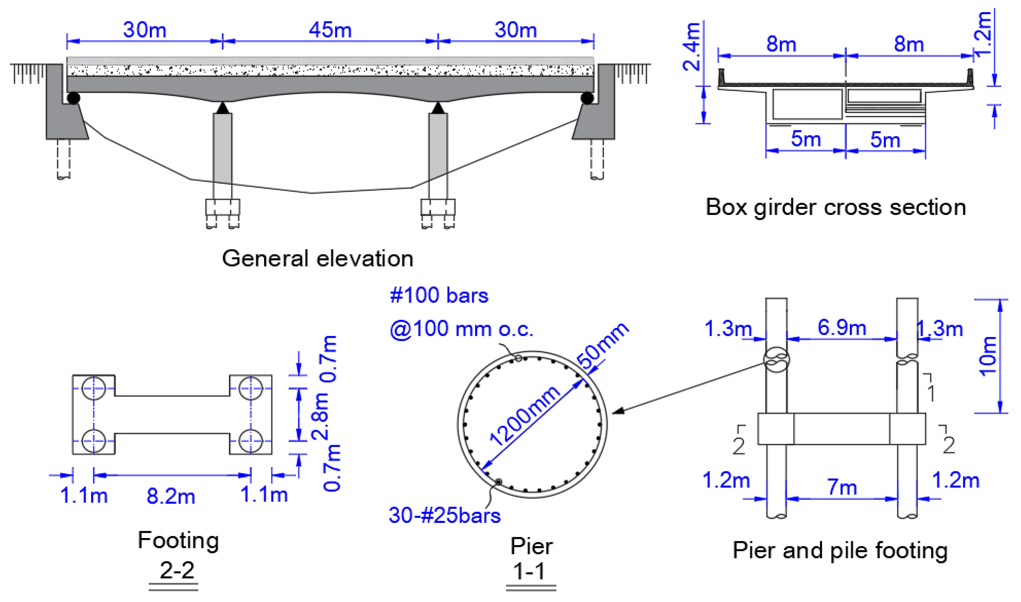
During the service period of RC structures, the mechanical properties of concrete would be deteriorated due to freeze–thaw damage, which may seriously impair their seismic performance [17,26,27]. In order to study the deterioration effects caused by free-thaw damage on C30 concrete, a deterioration model of RC columns was constructed. A typical three-span continuous girder bridge was selected as the example. Figure 4 displays the layout and configuration of the bridge. In this case, C30 concrete was used for RC columns of the bridge.
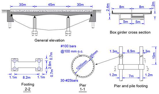
Figure 4.
The schematic details of the bridge.
OpenSEES [38,39,40,42,43] is an efficient nonlinear seismic analysis software, which has the advanced modeling capabilities and contains many material models, elements and algorithms for the seismic assessments of RC structures. Therefore, OpenSEES was utilized to construct the nonlinear FE model of the bridge. The superstructure was simulated by the elastic beam-column elements [38,39,42,43]. RC columns were modeled using the nonlinear beam-column elements [38,39,42,43]. Material model Concrete 04 was employed to simulate the cover and confined concrete, while Steel 02 was used to simulate steel bars. The bearings were all simulated by using the elastomeric bearing (plasticity) elements. Additionally, to simplify the modeling, the pile foundation system was modeled through linear elastic beam-column elements. Moreover, the transverse concrete stoppers were modeled using the hysteretic material and elastic-perfectly plastic gap elements [38,39,42,43]. The behavior of the abutments was simulated by considering the contributions made by the filled soils and piles, according to the method recommended by Caltrans [42,46].
For those bridges in the northern coastal areas of China, deterioration of RC columns is the primary reason causing the significant degradation in their structural resistance [15,17]. Therefore, this paper mainly studied the deterioration impacts caused by freeze–thaw cycling on the columns. To consider the uncertainties, a total of 17 random variables were considered, which are summarized in Table 2.

Table 2.
Statistical data of the considered random variables.
4.2. Selection of the Seismic Records
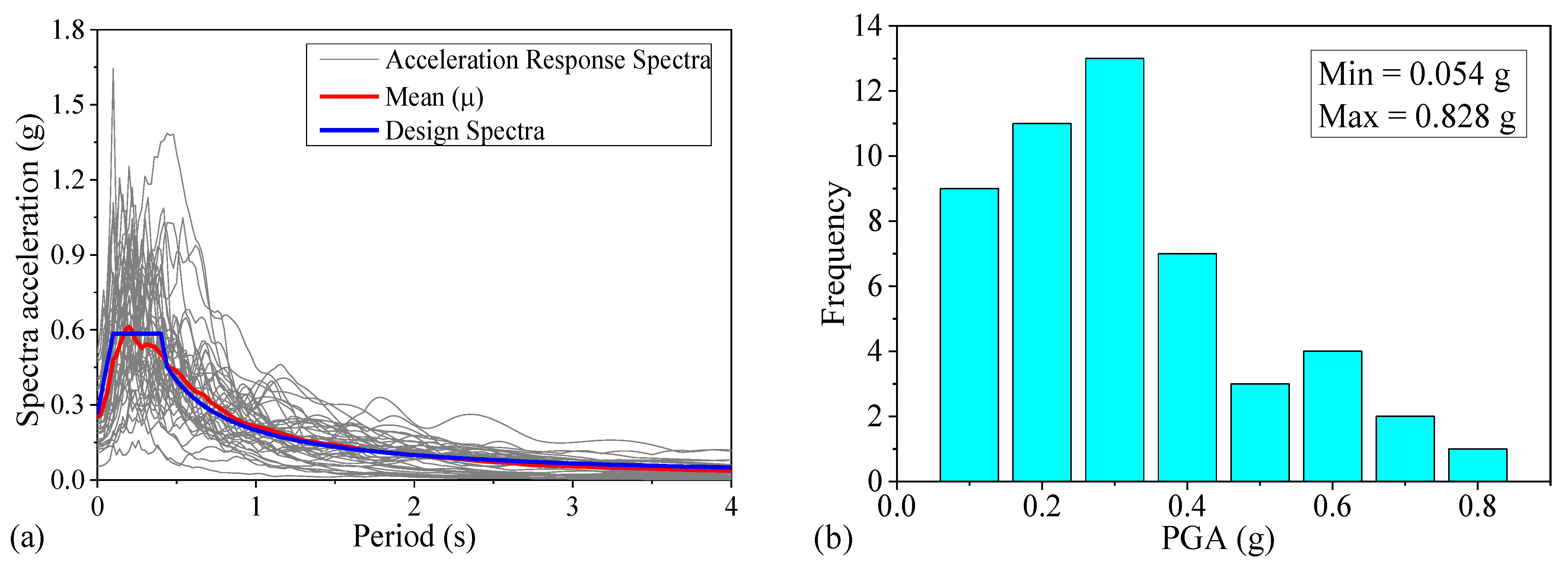
Based on the site conditions of the bridge, this paper selected 50 natural seismic records from the PEER Ground Motion Database [50]. Figure 5a displays the response spectra of the selected seismic records. As seen from Figure 5a, the mean value of acceleration spectra of the seismic records was consistent well with the target design response spectra according to [51]. Moreover, selection of the appropriate seismic IM is also critical. Based on several previous studies [52,53], the peak ground acceleration (PGA) is demonstrated to be a sufficient and practical IM. Thus, this study employed PGA as the seismic IM. Figure 5b shows the PGA distributions. As shown in Figure 5b, the selected seismic records covered a wide range of PGA. The moment magnitudes of the records were between 5.7 and 7.2 and their source distances were between 15 and 100 km, respectively.
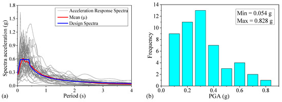
Figure 5.
Acceleration spectra and PGA distributions of the records: (a) acceleration spectra and (b) PGA distributions.
4.3. Application of the Proposed Deterioration Model
4.3.1. Variation in the Constitutive Parameters
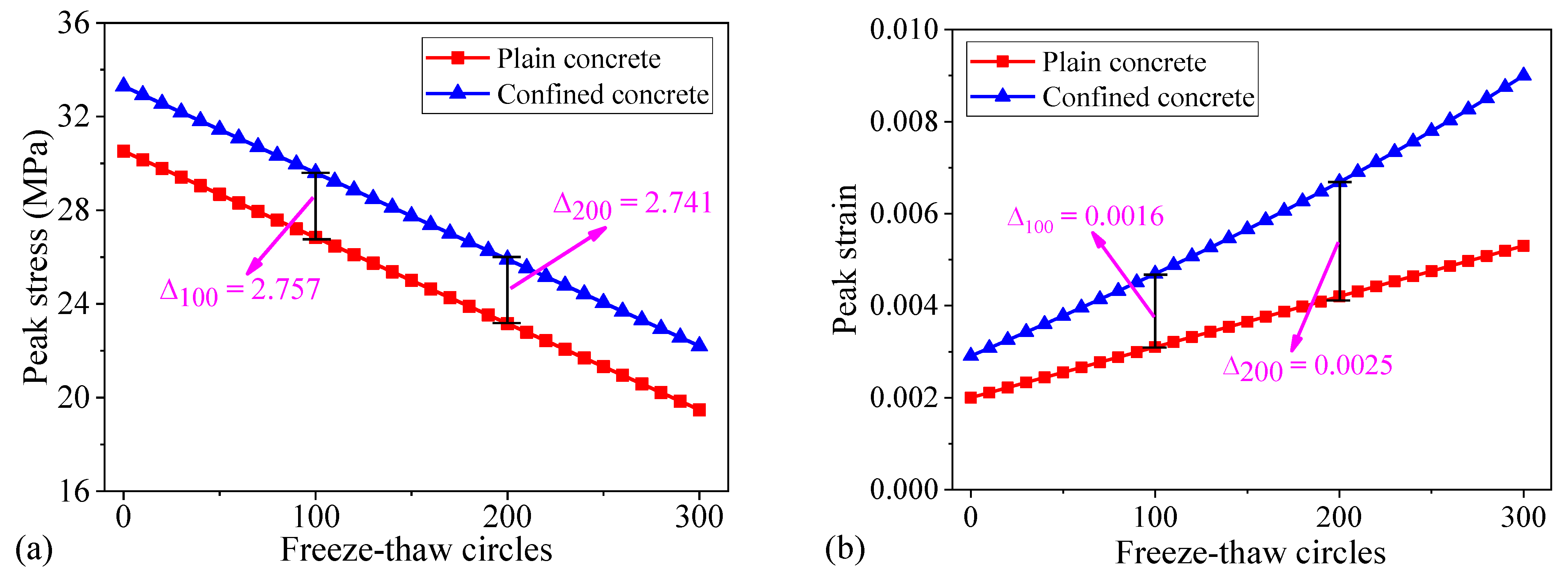
The proposed deterioration model was further applied to the seismic fragility analysis of RC columns of the bridge. Since the FE modeling of RC columns was simulated by using the distributed plasticity fiber-element model, seismic analysis of RC columns required the constitutive parameters of the concrete and steel bars. This paper mainly considered the deterioration effect of freeze–thaw damage on concrete. Figure 6 shows the variations of the peak strain and peak stress of RC columns under different freeze–thaw cycles. As seen from Figure 6, the peak stress and peak strain exhibited different trends as the increased of freeze–thaw cycles. For example, the peak stress decreased, whereas the peak strain increased with the increase of freeze–thaw cycles. Compared to the as-built columns, when freeze–thaw cycles was 150, the peak strain of plain concrete increased by 82.5%, while that of the confined concrete increased by 86.6%. Similarly, the peak stress of plain concrete reduced by 18.2%, whereas the peak stress of the confined concrete reduced by 16.64%. These observations suggested that the variations in the constitutive parameters of concrete due to the freeze–thaw damage should be carefully considered.
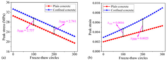
Figure 6.
The variations in the constitutive parameters of RC columns under different freeze–thaw cycles: (a) the peak stress and (b) the peak strain.
4.3.2. Seismic Fragility Analysis Considering the Freeze–Thaw Damage
In this case, 50 FE models of the bridge were generated by employing the uniform design method [38,39,42,46]. For simplicity, this paper only studied the longitudinal curvature ductility demand of the columns, which can be defined as the ratio of the maximum curvature to the curvature at which the outermost tensile bars first reaching the yield strength [33,34,40,42,45,49]. Linear regression analysis was performed by using Equation (17) to obtain the relevant PSDMs of the columns. The results are given in Table 3. As seen from Table 3, the logarithmic standard deviation of D increased with the freeze–thaw cycles. It increased by 6.57% after 150 freeze–thaw cycles. This means that the deterioration of RC structures due to the freeze–thaw damage may result in a greater uncertainty to the predictive results of the seismic response of the columns, which should be carefully addressed.

Table 3.
PSDMs of the columns.
Four damage states are defined based on the possible ductility levels of the columns [49], including (i) slight, (ii) moderate, (iii) extensive, and (iv) complete damage states. In specific, (1) the slight damage state is usually defined when steel bars reach the yielding strength; (2) the moderate damage state is defined following the concrete cracking; (3) the extensive damage state is defined when the concrete spalling is observed; and (4) the complete damage state is defined when steel bars are buckled, respectively [49]. The curvature ductility was employed as the damage index (DI). According to the available definitions of the damage states of RC columns in [45,49], the median values of the curvature ductility of the columns with the slight, moderate, extensive, and complete damage states are 1.29, 2.10, 3.52, and 5.24, respectively. In addition, the corresponding dispersion coefficients for these four damage states were assumed to be 0.59, 0.51, 0.64, and 0.65, respectively [45,49].
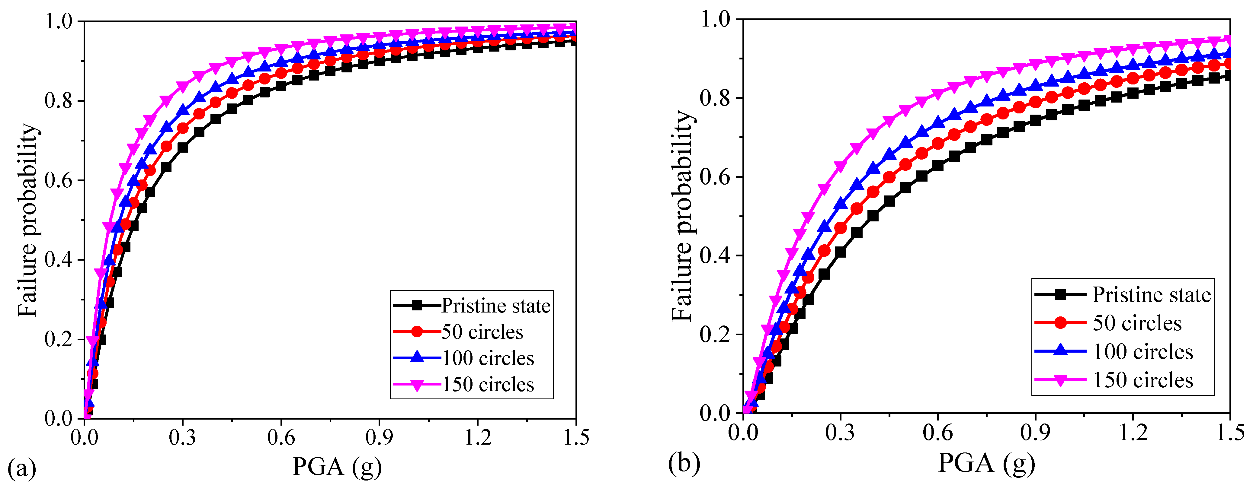
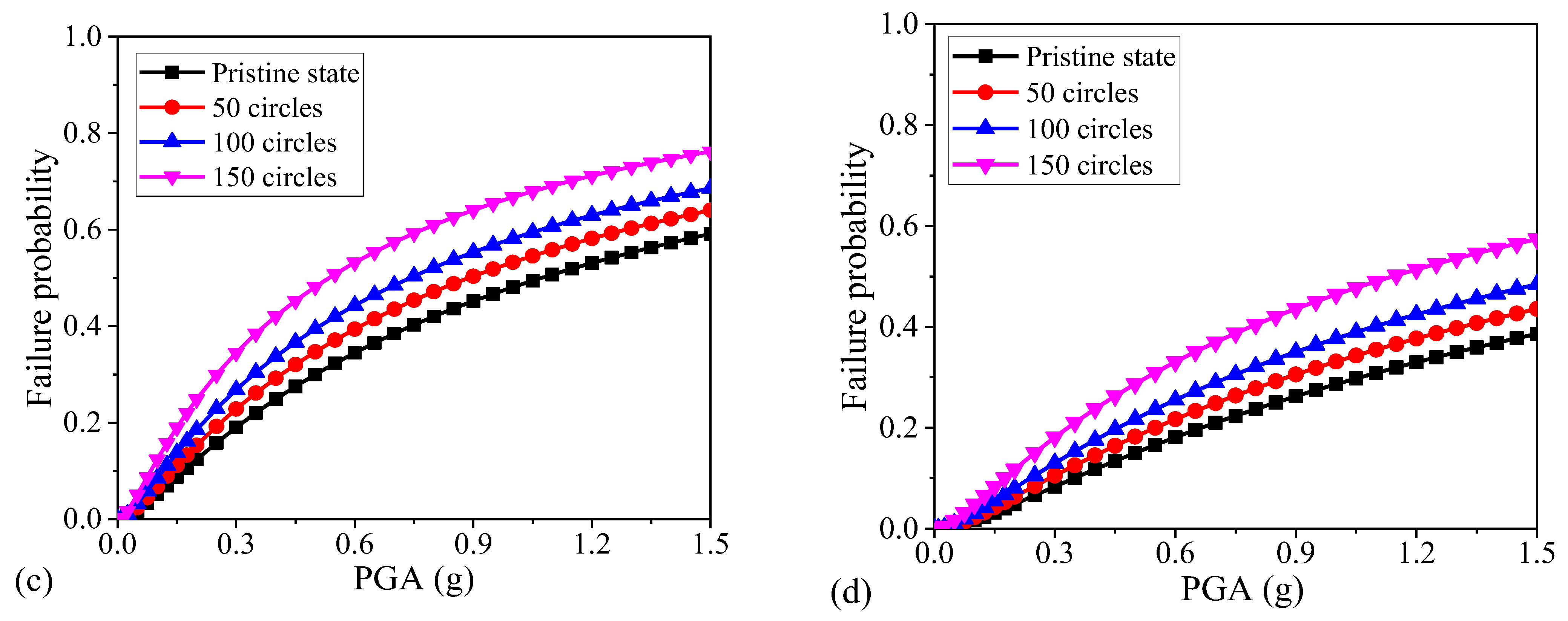
Figure 7 shows the generated fragility curves of the columns. As seen from Figure 7, the damage probability of the columns exceeded their ductility limit with the increase of freeze–thaw cycles, indicating the significance in considering the freeze–thaw damage on the deterioration of the concrete constitutive properties. In the first 100 freeze–thaw cycles, the growth of failure probability of the columns was relatively slow. Nevertheless, after 100 cycles, the growth of failure probability was relatively significant. For example, as shown in Figure 7c, for the pristine columns, the probability of extensive damage to the columns without freeze–thaw damage under a PGA of 0.6 g was 32.6%. However, after 150 freeze–thaw cycles, the probability of extensive damage exceeded 50%. Likewise, as shown in Figure 7d, compared to the as-built columns, the failure probability increased by 25.4% and 48.7% after 100 and 150 freeze–thaw cycles under a PGA of 1.5 g, respectively.
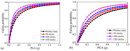
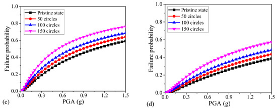
Figure 7.
Fragility curves of the columns under different freeze–thaw cycles: (a) slight, (b) moderate, (c) extensive, and (d) complete damage states.
5. Conclusions
In this paper, the test results available in the literature regarding the freeze–thaw damage to C30 concrete were summarized. Variations in the constitutive parameters of C30 concrete subjected to freeze–thaw cycles were analyzed. The deterioration model of RC columns with respect to freeze–thaw factors was proposed. This deterioration model could be used to study the seismic performance of RC columns in the northern frozen coastal areas of China. By taking a continuous girder bridge as the example, the seismic fragilities of RC columns considering the deterioration effects caused by freeze–thaw damage on the constitutive properties of concrete were performed. The probabilistic seismic demand, seismic capacity, and seismic fragilities of RC columns of the bridge were comprehensively investigated by considering the uncertainties involved in the deterioration of the material properties, geometric dimensions, structural modeling, and ground motions. The results indicate that freeze–thaw damage has significant effects on the constitutive properties of concrete and it should be carefully considered in dealing with the probabilistic seismic demand and capacity, as well as fragility assessment of RC columns. In addition, the seismic fragilities of RC columns tend to exhibit a nonlinear increase trend with the severity of the damage state and the number of freeze–thaw cycles.
Moreover, this study provides new insights into the deterioration effects on the constitutive parameters of concrete caused by freeze–thaw damage, and it also investigates such deterioration effects on the seismic response and vulnerabilities of RC columns comprehensively for the first time. This paper mainly studies the seismic performance of RC columns affected by the freeze–thaw damage, which is significant in the investigations on the seismic performance of RC structures under the influences of multiple factors, such as the composite actions of freeze–thaw cycling and chloride-induced corrosion. Furthermore, in this paper, RC columns are mainly subjected to bending failure, and the shear failure belongs to the brittle failure. This paper does not specifically analyze the influence of shear failure, and it should be further studied in future. The established deterioration model is based on the material tests. The constitutive model of plain concrete has been verified, but relevant experimental studies should be further carried out to fully verify the validation of the constitutive model of the confined concrete in future.
Author Contributions
Conceptualization, F.C. and H.L.; methodology, F.C. and H.L.; software, G.G., L.C. and M.L.; validation, F.C., G.G., L.C. and M.L.; formal analysis, G.G., L.C. and M.L.; investigation, G.G., L.C. and M.L.; resources, F.C. and S.D.; data curation, G.G., L.C. and M.L.; writing—original draft preparation, F.C., G.G., L.C. and M.L.; writing—review and editing, H.L.; visualization, M.L., S.D. and H.L.; supervision, F.C. and H.L.; project administration, F.C. and S.D.; funding acquisition, F.C. and S.D.. All authors have read and agreed to the published version of the manuscript.
Funding
The research described in this paper was supported by the “Shandong Natural Science Foundation Project” (Project No. 60000101032); the National Natural Science Foundation of China (Grant No. 52108211); Hunan Provincial Department of Education (No. 21B0188); and the Natural Science Foundation of Hunan Province (No. 2022JJ40186). The authors greatly acknowledge their financial supports.
Institutional Review Board Statement
Not applicable.
Informed Consent Statement
Not applicable.
Acknowledgments
The research described in this paper was supported by the “Shandong Natural Science Foundation Project” (Project No. 60000101032); the National Natural Science Foundation of China (Grant No. 52108211); Hunan Provincial Department of Education (No. 21B0188); and the Natural Science Foundation of Hunan Province (No. 2022JJ40186). The authors greatly acknowledge their financial supports.
Conflicts of Interest
The authors declare that they have no known competing financial interests or personal relationships that could have appeared to influence the work reported in this paper.
References
- Zhang, K.; Zhou, J.; Yin, Z. Experimental study on mechanical properties and pore structure deterioration of concrete under freeze–thaw cycles. Materials 2021, 14, 6568. [Google Scholar] [CrossRef] [PubMed]
- Zhang, X.; Guan, J.; Chen, X.; Pei, W.; Yu, S.; Wang, Y.; Wang, W. Effect of permafrost on seismic performance of railway bridge pile foundation with elevated cap. Int. J. Struct. Stab. Dyn. 2022, 22, 2241002. [Google Scholar] [CrossRef]
- Gong, F.; Maekawa, K. Multi-scale simulation of freeze-thaw damage to RC column and its restoring force characteristics. Eng. Struct. 2018, 156, 522–536. [Google Scholar] [CrossRef]
- Billah, A.; Todorov, B. Effects of subfreezing temperature on the seismic response of lead rubber bearing isolated bridge. Soil Dyn. Earthq. Eng. 2019, 126, 65–72. [Google Scholar] [CrossRef]
- Yu, H.; Ma, H.; Yan, K. An equation for determining freeze-thaw fatigue damage in concrete and a model for predicting the service life. Constr. Build. Mater. 2017, 137, 104–116. [Google Scholar] [CrossRef]
- Si, Z.; Du, X.; Huang, L.; Li, Y. Meso-scale failure of freezing–thawing damage of concrete under uniaxial compression. Appl. Sci. 2020, 10, 1252. [Google Scholar] [CrossRef]
- Li, B.; Mao, J.; Shen, W.; Liu, H.; Liu, X.; Xu, G. Mesoscopic cracking model of cement-based materials subjected to freeze-thaw cycles. Constr. Build. Mater. 2019, 211, 1050–1064. [Google Scholar] [CrossRef]
- Xu, G.; Zeng, J.; Wang, Q.; Xiang, X.; Wei, Z. Bond stress-slip model for concrete-embedded smooth bars in salt-frozen environment. IOP Conf. Ser. Earth Environ. Sci. 2019, 304, 052081. [Google Scholar] [CrossRef]
- Wang, X.; Petru, M. Freeze–thaw resistance of epoxy/concrete interface evaluated by a novel wedge splitting test. Constr. Build. Mater. 2019, 210, 434–441. [Google Scholar] [CrossRef]
- Gong, F.; Takahashi, Y.; Maekawa, K. Multi-scale computational modeling for concrete damage by mixed pore pressures—Case of coupled alkali–silica reaction and cyclic freeze-thaw. Eng. Comput. 2018, 35, 2367–2385. [Google Scholar] [CrossRef]
- Liu, K.; Yan, J.; Alam, M.; Zou, C. Seismic fragility analysis of deteriorating recycled aggregate concrete bridge columns subjected to freeze-thaw cycles. Eng. Struct. 2019, 187, 1–15. [Google Scholar] [CrossRef]
- Yu, X.; Chen, L.; Fang, Q.; Ruan, Z.; Hong, J.; Xiang, H. A concrete constitutive model considering coupled effects of high temperature and high strain rate. Int. J. Impact Eng. 2017, 101, 66–77. [Google Scholar] [CrossRef]
- Niu, D.; Zhang, G.; Luo, D.; Guan, X.; Liu, X. Research on frost resistance of reinforced concrete in extreme freeze-thaw environment. Ind. Constr. 2019, 49, 1–6. (In Chinese) [Google Scholar]
- Zhang, D.; Mao, M.; Zhang, S.; Yang, Q. Influence of stress damage and high temperature on the freeze–thaw resistance of concrete with fly ash as fine aggregate. Constr. Build. Mater. 2019, 229, 116845. [Google Scholar] [CrossRef]
- Plotnikova, A.; Wotherspoon, L.; Beskhyroun, S.; Yang, Z. Influence of seasonal freezing on dynamic bridge characteristics using in-situ monitoring data. Cold Reg. Sci. Technol. 2019, 160, 184–193. [Google Scholar] [CrossRef]
- Zheng, S.; Zheng, Y.; Liu, H.; Zhang, Y. Seismic performance and numerical simulation method of chloride corrosion RC joints. J. Huazhong Univ. Sci. Technol. 2021, 49, 109–115. [Google Scholar]
- Li, Y.; Yin, S.; Lv, H. Combined effects of dry-wet cycles and sustained loads on the seismic behavior of TRC-strengthened RC columns. Structures 2021, 33, 2226–2237. [Google Scholar] [CrossRef]
- Liu, S.; Du, M.; Tian, Y.; Wang, X.; Sun, G. Bond behavior of reinforced concrete considering freeze–thaw cycles and corrosion of stirrups. Materials 2021, 14, 4732. [Google Scholar] [CrossRef]
- Ma, K.; Li, S.; Long, G.; Xie, Y.; Yu, L.; Xie, Q. Performance evolution and damage constitutive model of thin layer SCC under the coupling effect of freeze–thaw cycles and load. J. Mater. Civ. Eng. 2020, 32, 04020147. [Google Scholar] [CrossRef]
- Gong, F.; Ueda, T.; Wang, Y.; Zhang, D.; Wang, Z. Mesoscale simulation of fatigue behavior of concrete materials damaged by freeze-thaw cycles. Constr. Build. Mater. 2017, 144, 702–716. [Google Scholar] [CrossRef]
- Niu, D.; Wang, J.; He, H. Frost durability and stress–strain relationship of lining shotcrete in cold environment. Constr. Build. Mater. 2019, 198, 58–69. [Google Scholar]
- Duan, A.; Jin, W.; Qian, J. Effect of freeze–thaw cycles on the stress–strain curves of unconfined and confined concrete. Mater. Struct. 2011, 44, 3–15. [Google Scholar] [CrossRef]
- Ma, B.; Ye, Y.; Sun, Y. Mechanical Properties Analysis of salt corrosion and freeze-thaw concrete based on damage model. J. Build. Struct. 2009, 30, 298–302. [Google Scholar]
- Qiu, W.; Teng, F.; Pan, S. Damage constitutive model of concrete under repeated load after seawater freeze-thaw cycles. Constr. Build. Mater. 2020, 236, 3–11. [Google Scholar] [CrossRef]
- Zhu, X.; Chen, X.; Bai, Y.; Ning, Y.; Zhang, W. Evaluation of fracture behavior of high-strength hydraulic concrete damaged by freeze-thaw cycle test. Constr. Build. Mater. 2022, 321, 126346. [Google Scholar] [CrossRef]
- Li, Y.; Li, B.; Zhang, L.; Ma, C. Damage evolution of concrete piles mixed with admixtures in marine corrosion and freeze-thaw environment. Geofluids 2021, 2021, 1393881. [Google Scholar] [CrossRef]
- Yang, H.; Liu, C.; Jiang, J. Damage constitutive model of stirrup-confined recycled aggregate concrete after freezing and thawing cycles. Constr. Build. Mater. 2020, 253, 1148–1162. [Google Scholar] [CrossRef]
- Li, B.; Mao, J.; Nawa, T.; Han, T. Mesoscopic damage model of concrete subjected to freeze-thaw cycles using mercury intrusion porosimetry and differential scanning calorimetry (MIP-DSC). Constr. Build. Mater. 2017, 147, 79–90. [Google Scholar] [CrossRef]
- Sun, M.; Xin, D.; Zou, C. Damage evolution and plasticity development of concrete materials subjected to freeze-thaw during the load process. Mech. Mater. 2019, 139, 2145–2159. [Google Scholar] [CrossRef]
- Gong, X.; Yu, H.; Wu, C. Research on the constitutive relationship of concrete under uniaxial compression in freeze–thaw environment. Constr. Build. Mater. 2022, 336, 1617–1626. [Google Scholar] [CrossRef]
- Zheng, S.; Zheng, Y.; Dong, L. Constitutive model of corroded stirrup restrained concrete in offshore environment. J. Zhejiang Univ. 2020, 54, 48–55. (In Chinese) [Google Scholar]
- Teng, F. Study on Seismic Behavior of Reinforced Concrete Piers after Sea Water Freezing-Thawing Cycle; Dalian University of Technology: Dalian, China, 2021; pp. 48–55. [Google Scholar]
- Choi, E.; DesRoches, R.; Nielson, B. Seismic fragility of typical bridges in moderate seismic zones. Eng. Struct. 2004, 26, 187–199. [Google Scholar] [CrossRef]
- Nielson, B.; DesRoches, R. Seismic fragility methodology for highway bridges using a component level approach. Earthq. Eng. Struct. Dyn. 2007, 36, 823–839. [Google Scholar] [CrossRef]
- Wu, W.; Li, L.; Shao, X. Seismic assessment of medium-span concrete cable-stayed bridges using the component and system fragility functions. J. Bridge Eng. 2016, 21, 04016027. [Google Scholar] [CrossRef]
- Işık, E.; Harirchian, E.; Bilgin, H.; Jadhav, K. The effect of material strength and discontinuity in RC structures according to different site-specific design spectra. Res. Eng. Struct. Mater. 2021, 7, 413–430. [Google Scholar] [CrossRef]
- Cirak, C.; Palanci, M.; Senel, S. Fragility based evaluation of different code based assessment approaches for the performance estimation of existing buildings. Bull. Earthq. Eng. 2022, 20, 1685–1716. [Google Scholar] [CrossRef]
- Li, H.; Li, L.; Zhou, G.; Xu, L. Effects of various modeling uncertainty parameters on the seismic response and seismic fragility estimates of the aging highway bridges. Bull. Earthq. Eng. 2020, 18, 6337–6373. [Google Scholar] [CrossRef]
- Li, H.; Li, L.; Zhou, G.; Xu, L. Time-dependent seismic fragility assessment for aging highway bridges subject to non-uniform chloride-induced corrosion. J. Earthq. Eng. 2022, 26, 3523–3553. [Google Scholar] [CrossRef]
- Bülbül, M.; Harirchian, E.; Işık, M.; Aghakouchaki Hosseini, S.; Işık, E. A hybrid ANN-GA model for an automated rapid vulnerability assessment of existing RC buildings. Appl. Sci. 2022, 12, 5138. [Google Scholar] [CrossRef]
- Su, Z.; Tan, X.; Chen, W.; Jia, H.; Xu, F. A model of unfrozen water content in rock during freezing and thawing with experimental validation by nuclear magnetic resonance. J. Rock Mech. Geotech. Eng. 2022, 14, 1545–1555. [Google Scholar] [CrossRef]
- Cui, F.; Li, H.; Dong, X.; Wang, B.; Li, J.; Xue, H.; Qi, M. Improved time-dependent seismic fragility estimates for deteriorating RC bridge substructures exposed to chloride attack. Adv. Struct. Eng. 2021, 24, 437–452. [Google Scholar] [CrossRef]
- Li, H.; Zhou, G.; Wang, J. Selection of ground motion intensity measures and evaluation of the ground motion-related uncertainties in the probabilistic seismic demand analysis of highway bridges. Buildings 2022, 12, 1184. [Google Scholar] [CrossRef]
- Alipour, A.; Shafei, B.; Shinozuka, M. Performance evaluation of deteriorating highway bridges located in high seismic areas. J. Bridge Eng. 2011, 16, 597–611. [Google Scholar] [CrossRef]
- Cornell, C. Probabilistic basis for 2000 SAC federal emergency management agency steel moment frame guidelines. J. Struct. Eng. 2002, 128, 526–533. [Google Scholar] [CrossRef]
- Pang, Y.; Wu, X.; Shen, G.; Yuan, W. Seismic fragility analysis of cable-stayed bridges considering different sources of uncertainties. J. Bridge Eng. 2014, 19, 04013015. [Google Scholar] [CrossRef]
- Barbato, M.; Gu, Q.; Conte, J. Probabilistic push-over analysis of structural and soil-structure systems. J. Struct. Eng. 2010, 136, 1330–1341. [Google Scholar] [CrossRef]
- Darmawan, M.; Stewart, M. Spatial time-dependent reliability analysis of corroding pretensioned prestressed concrete bridge girders. Struct. Saf. 2007, 29, 16–31. [Google Scholar] [CrossRef]
- Nielson, B. Analytical Fragility Curves for Highway Bridges in Moderate Seismic Zones. Ph.D. Thesis, School of Civil and Environmental Engineering, Georgia Institute of Technology, Atlantic, NJ, USA, 2005; pp. 1–24. [Google Scholar]
- PEER (Pacific Earthquake Engineering Research Center). PEER Ground Motion Database; PEER: Berkeley, CA, USA, 2013. [Google Scholar]
- JTG/T B02–01; Guidelines for Seismic Design of Chinese Highway Bridges. Ministry of Transport of the People’s Republic of China: Beijing, China, 2008.
- Cao, X.; Feng, D.; Wang, Z.; Wu, G. Parametric investigation of the assembled bolt-connected buckling-restrained brace and performance evaluation of its application into structural retrofit. J. Build. Eng. 2022, 48, 103988. [Google Scholar] [CrossRef]
- Cao, X.; Feng, D.; Li, Y. Assessment of various seismic fragility analysis approaches for structures excited by non-stationary stochastic ground motions. Mech. Syst. Signal Process. 2023, 186, 109838. [Google Scholar] [CrossRef]
Disclaimer/Publisher’s Note: The statements, opinions and data contained in all publications are solely those of the individual author(s) and contributor(s) and not of MDPI and/or the editor(s). MDPI and/or the editor(s) disclaim responsibility for any injury to people or property resulting from any ideas, methods, instructions or products referred to in the content. |
© 2023 by the authors. Licensee MDPI, Basel, Switzerland. This article is an open access article distributed under the terms and conditions of the Creative Commons Attribution (CC BY) license (https://creativecommons.org/licenses/by/4.0/).

