


Degradation of Reinforced Concrete Beams Subjected to Sustained Loading and Multi-Environmental Factors


Abstract
:1. Introduction
2. Experimental Program
2.1. Materials
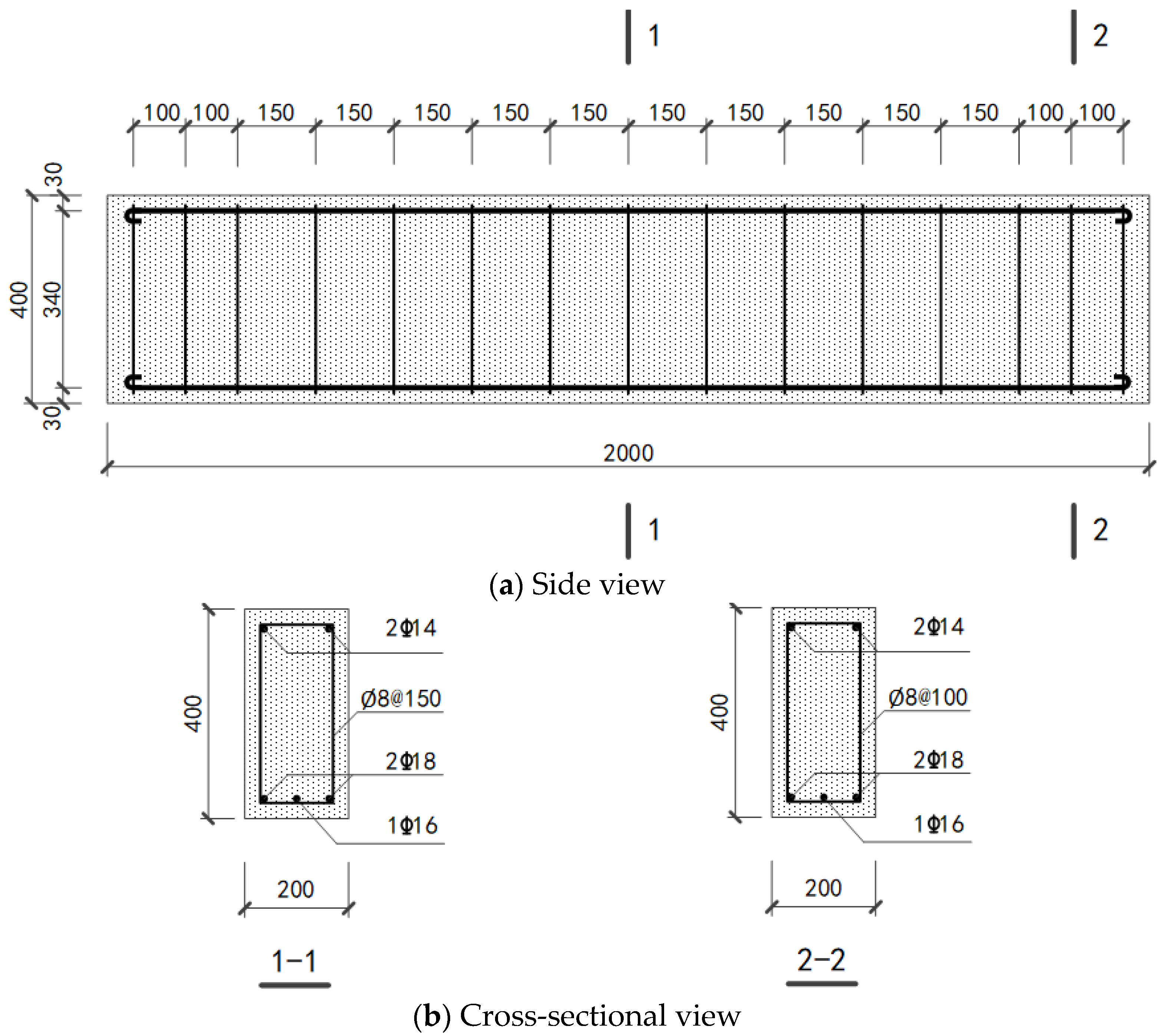
2.2. Beam Specimen
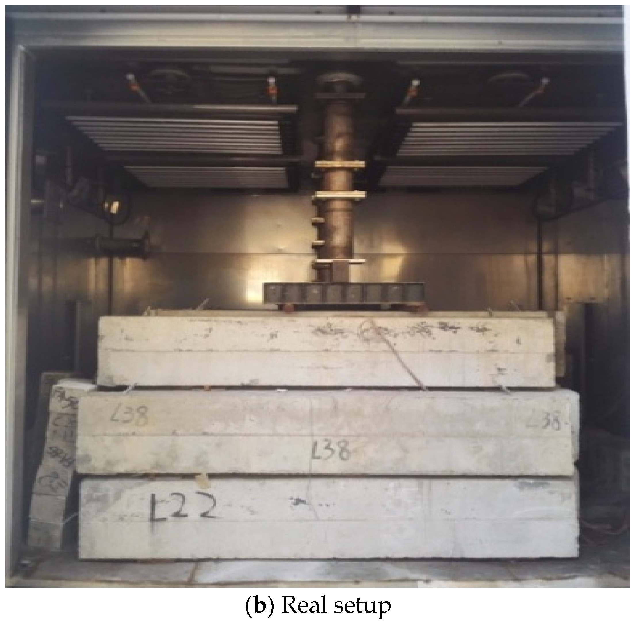
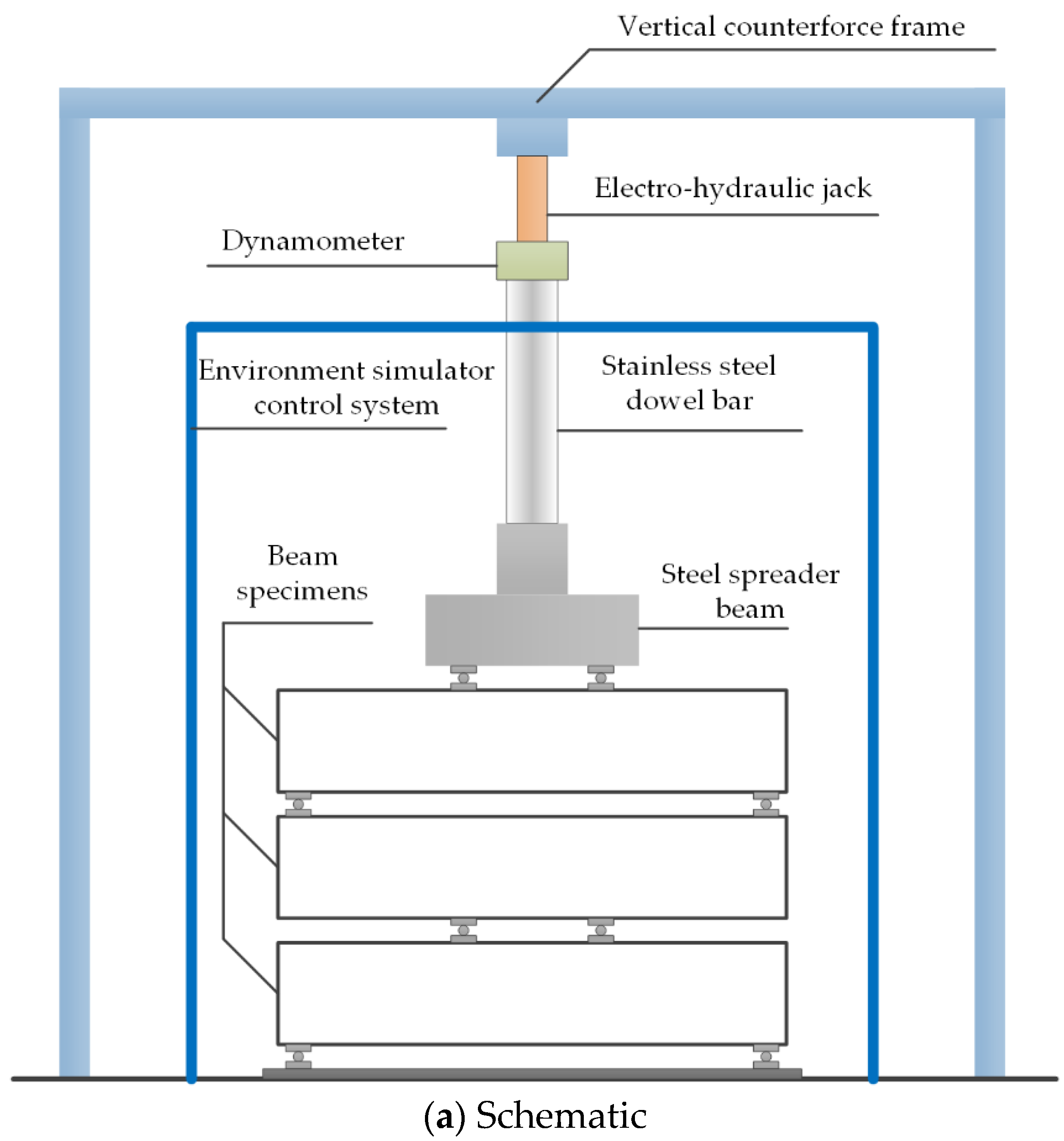
2.3. Accelerated Deterioration Experiment of Reinforced Concrete Beams Subjected to Sustained Loading and Multi-Environmental Factors
3. Experimental Results and Mechanism Discussion
3.1. Degradation of Concrete
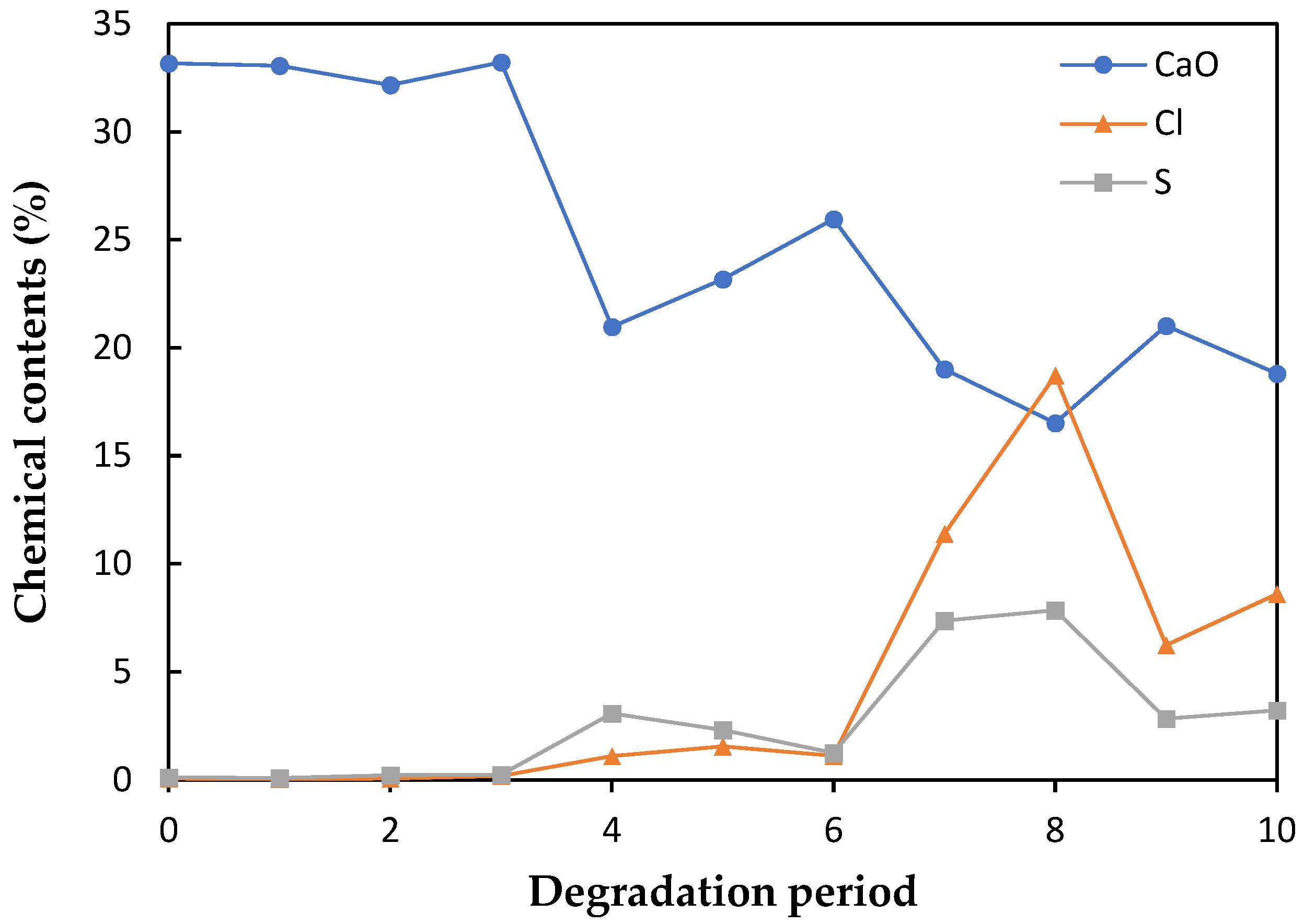
3.1.1. Chemical Contents of Concrete Beam Surfaces
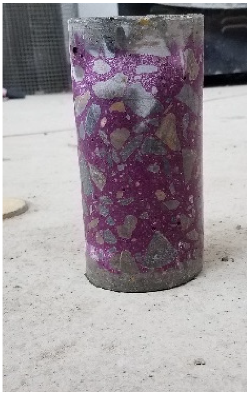
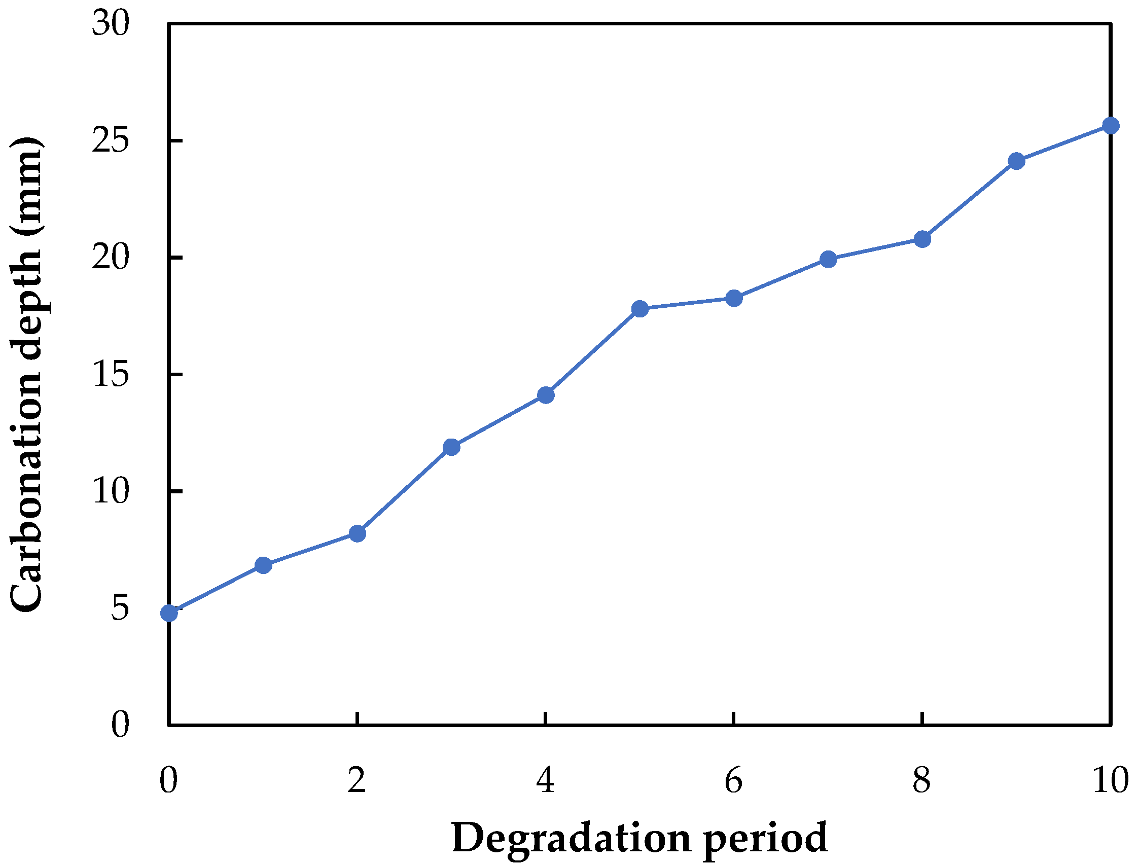
3.1.2. Carbonation Depth
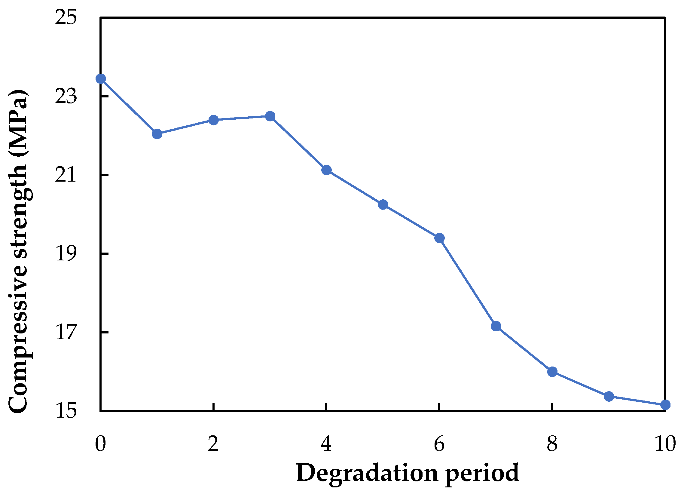
3.1.3. Compressive Strength
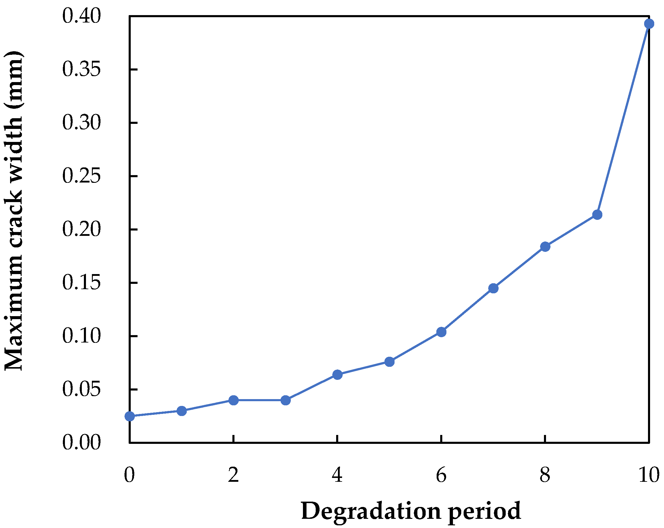
3.1.4. Maximum Crack Width
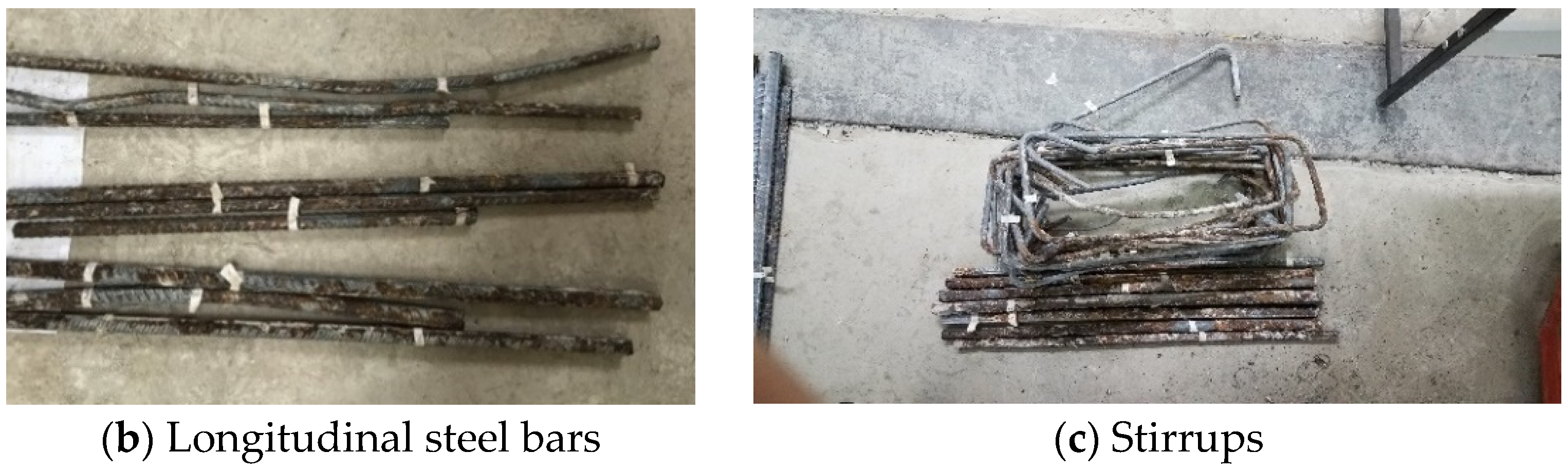
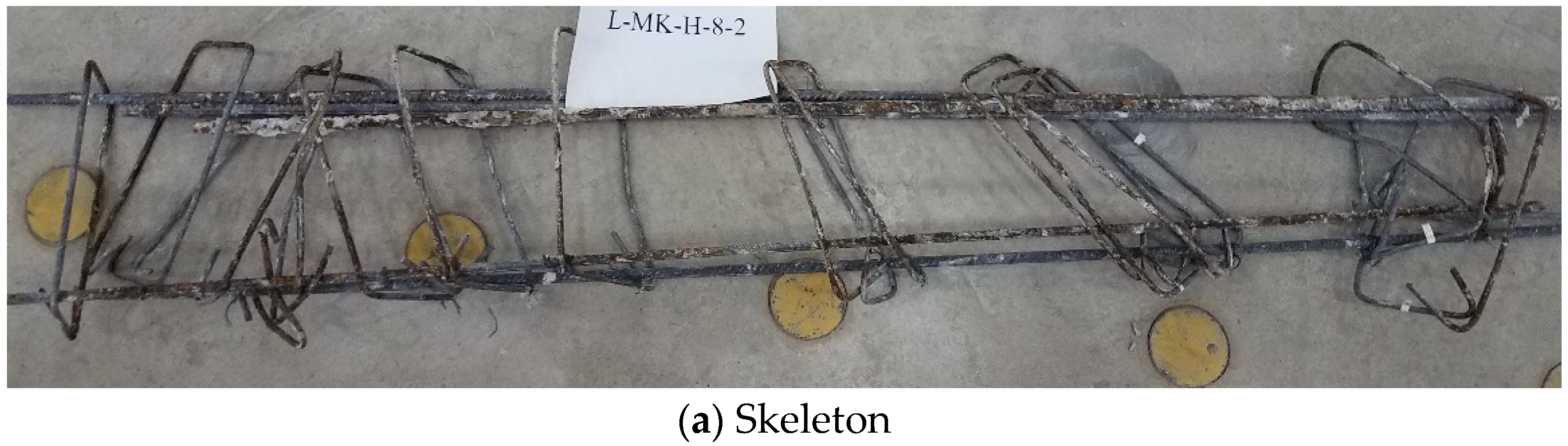
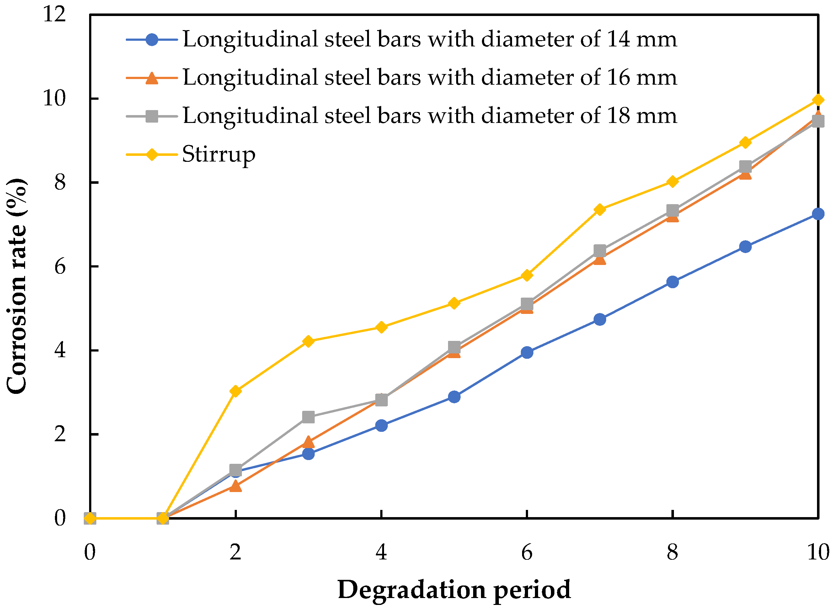
3.2. Corrosion of Steel Bars
3.2.1. Corrosion Rate
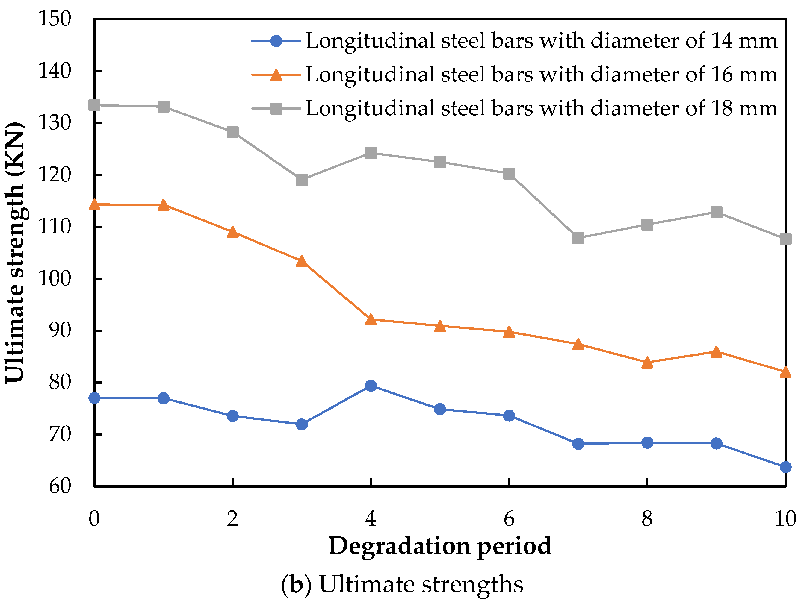
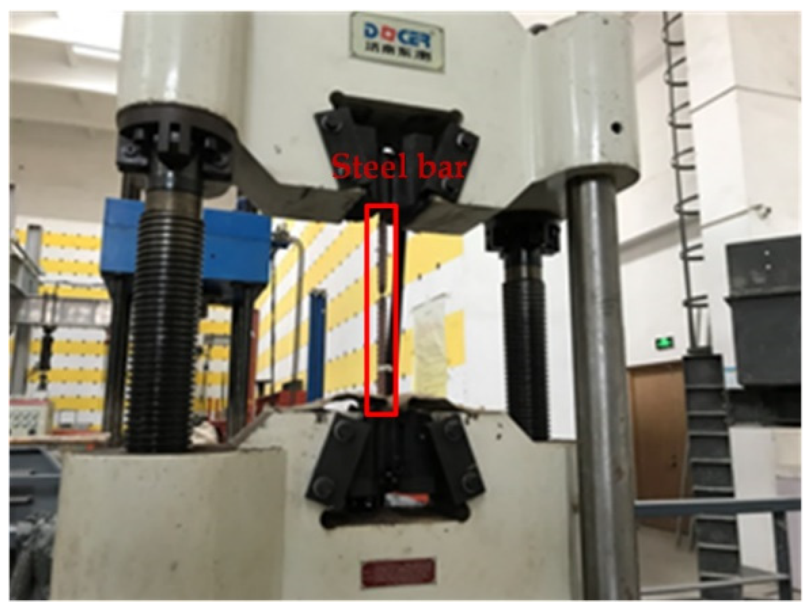
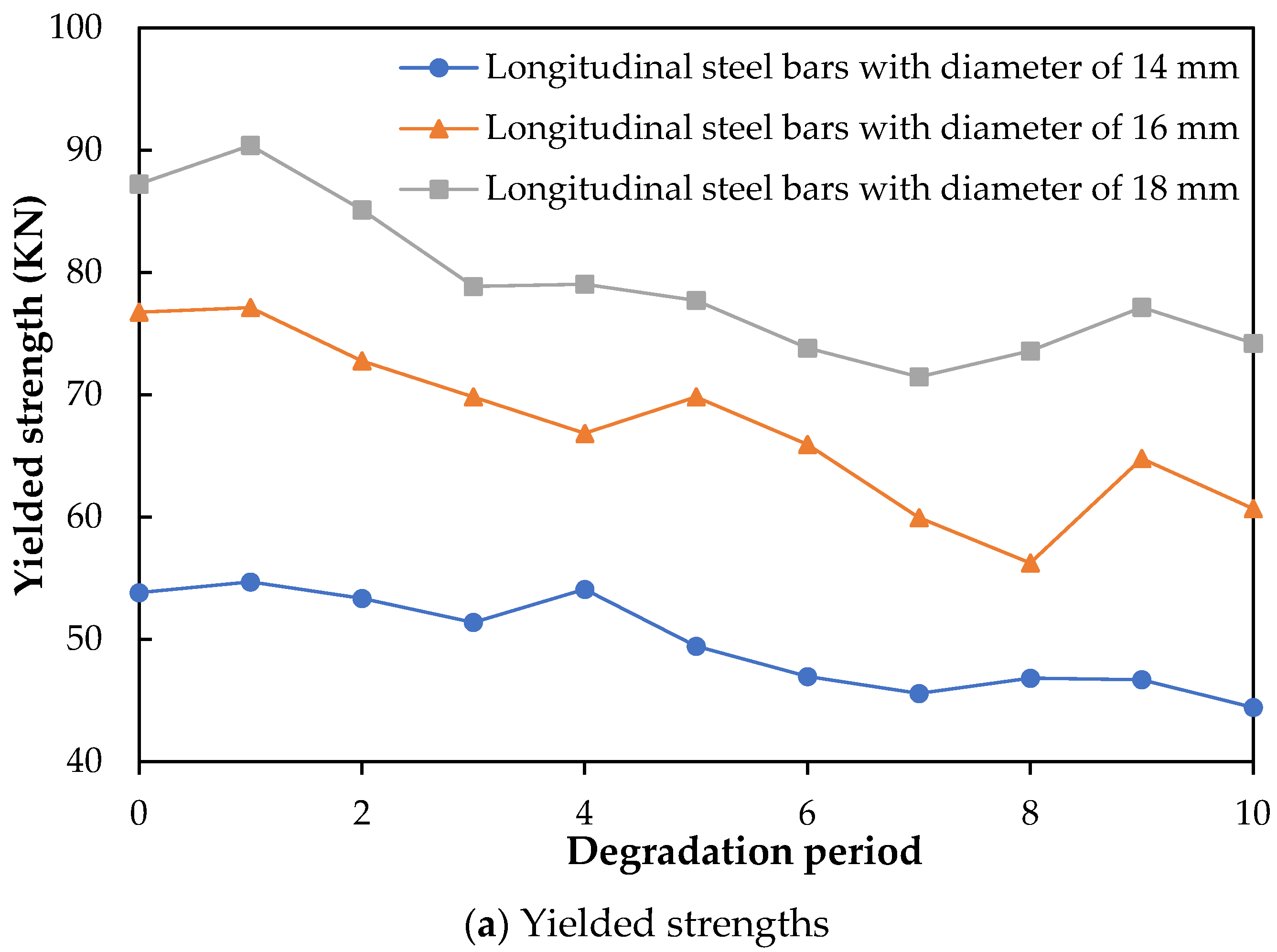
3.2.2. Tensile Strength
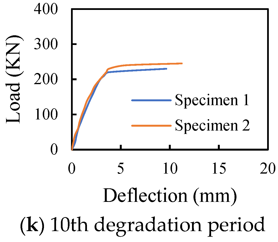
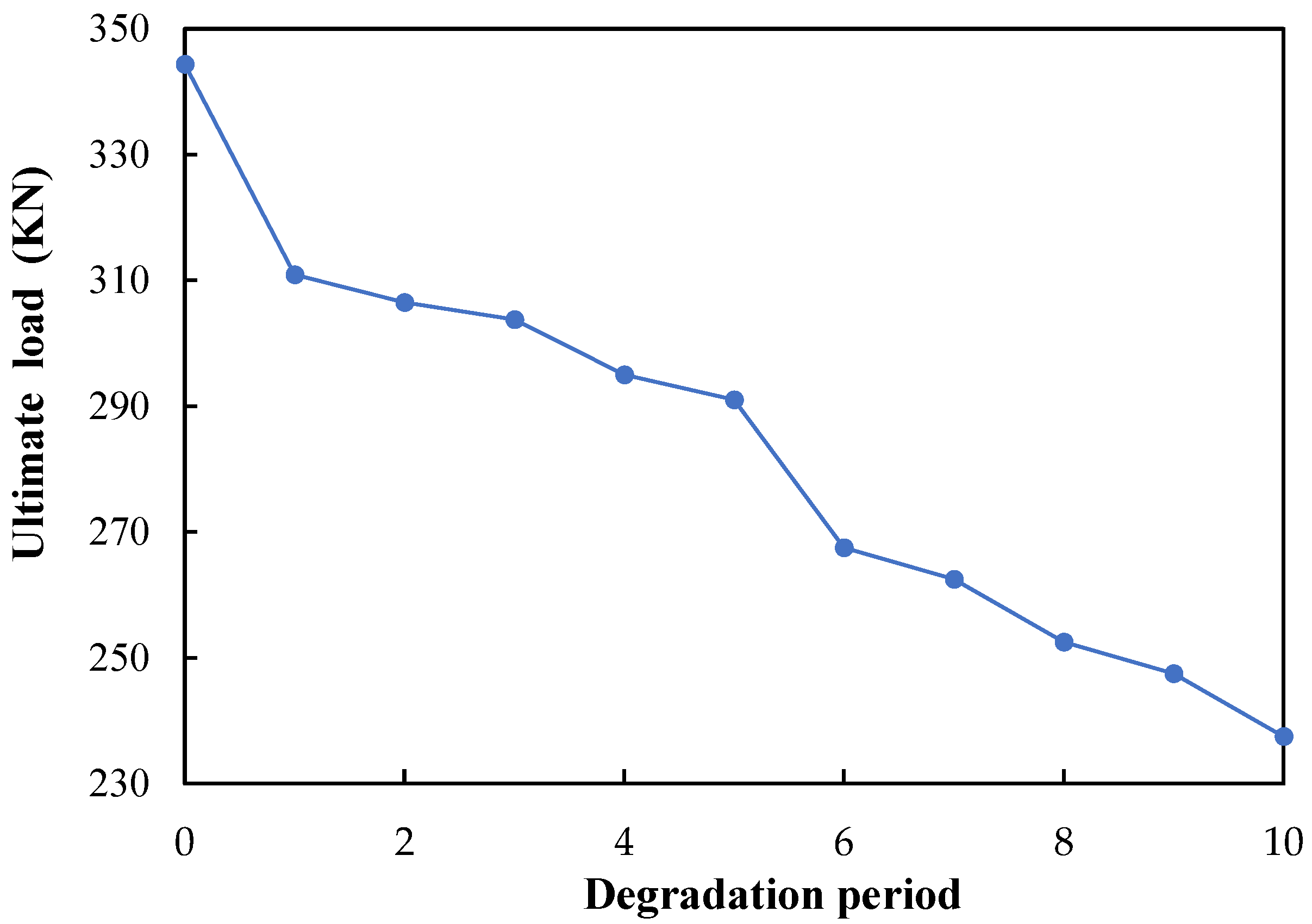
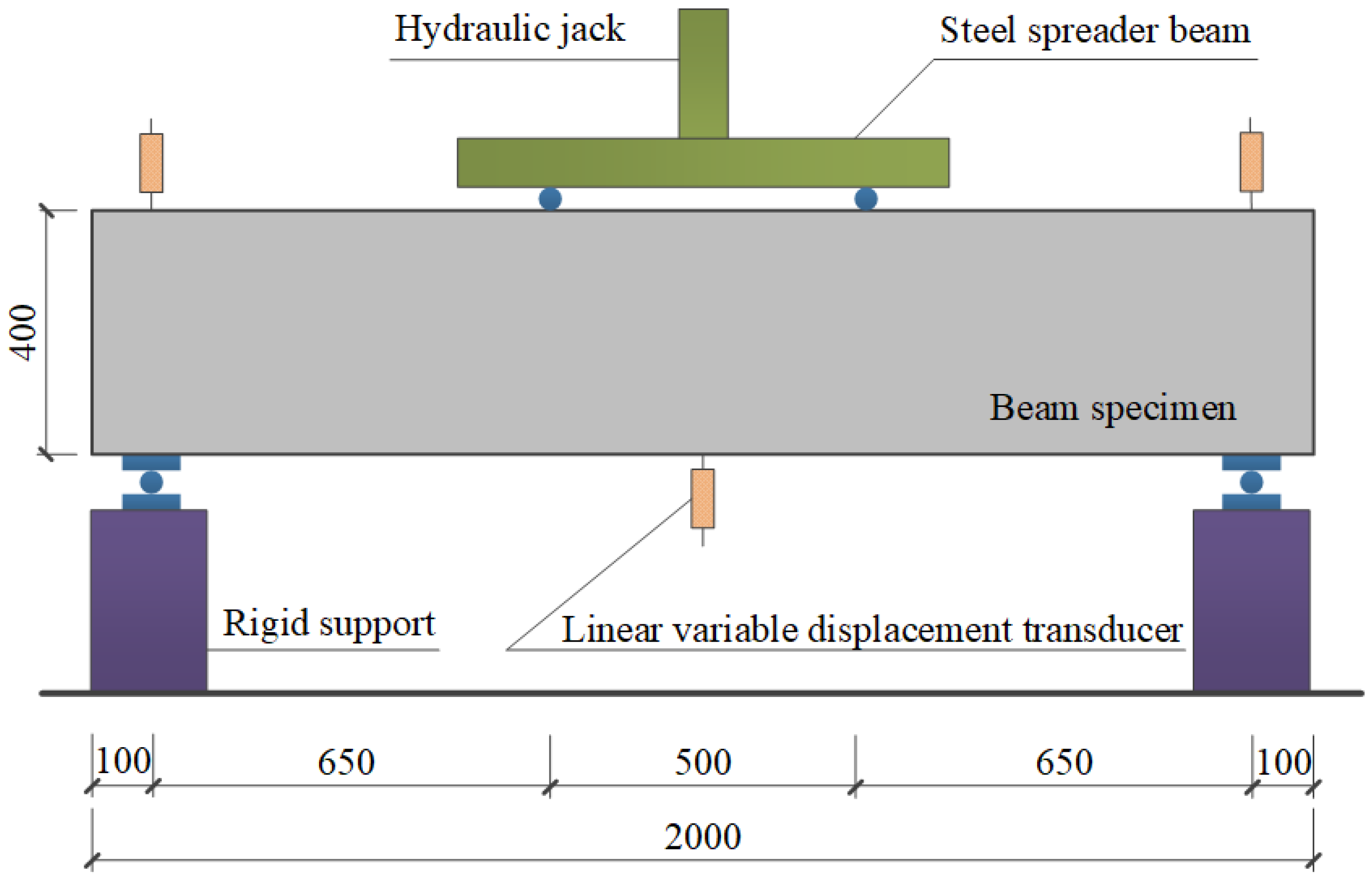
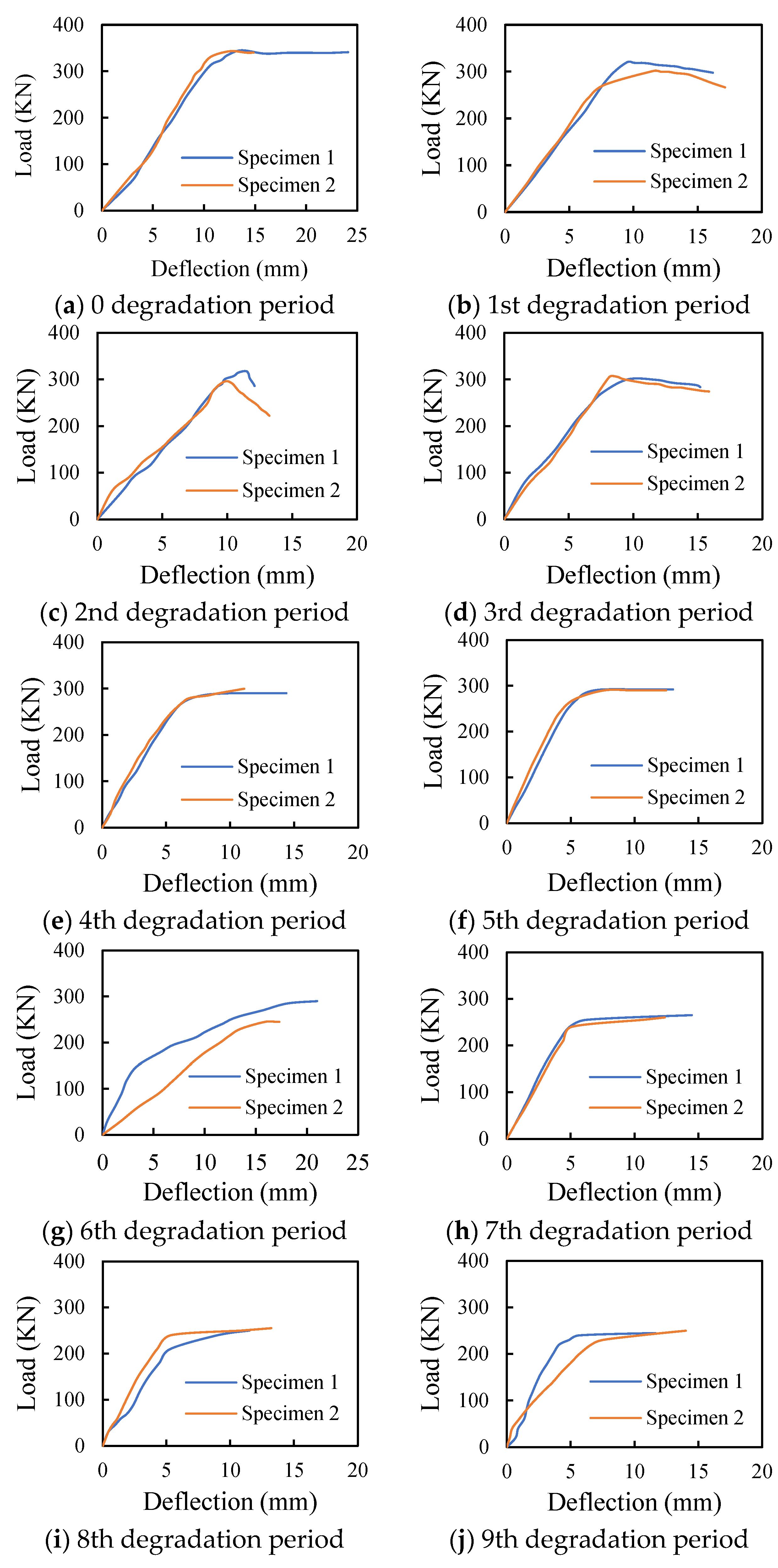
3.3. Flexural Performance of Degraded and Reinforced Concrete Beams
4. Conclusions
Author Contributions
Funding
Institutional Review Board Statement
Informed Consent Statement
Data Availability Statement
Conflicts of Interest
References
- Lv, H.L.; Wu, Y.Z.; Fang, Z.N.; Zhou, S.C. Deterioration behavior of reinforced concrete beam under compound effects of acid-salt mist and carbon dioxide. Construct. Build. Mater. 2015, 77, 253–259. [Google Scholar] [CrossRef]
- Qu, F.L.; Li, W.G.; Dong, W.K.; Tam, V.W.Y.; Yu, T. Durability deterioration of concrete under marine environment from material to structure: A critical review. J. Build. Eng. 2021, 35, 102074. [Google Scholar] [CrossRef]
- Hossain, K.M.A. Pumice based blended cement concretes exposed to marine environment: Effects of mix composition and curing conditions. Cement Concr. Compos. 2008, 30, 97–105. [Google Scholar] [CrossRef]
- Yue, P.J.; Tan, Z.Y.; Guo, Z.Y. Microstructure and mechanical properties of recycled aggregate concrete in seawater environment. Sci. World J. 2013, 2013, 306714. [Google Scholar] [CrossRef] [PubMed]
- Zhang, Y.; Zhang, M.Z.; Ye, G. Influence of moisture condition on chloride diffusion in partially saturated ordinary Portland cement mortar. Mater. Struct. 2018, 51, 36. [Google Scholar] [CrossRef]
- Qiao, C.Y.; Ni, W.; Weiss, J. Transport due to diffusion, drying, and wicking in concrete containing a shrinkage-reducing admixture. J. Mater. Civ. Eng. 2017, 29, 04017146. [Google Scholar] [CrossRef]
- Justnes, H. A review of chloride binding in cementitious systems. Nord. Concr. Res. Publicat. 1998, 21, 48–63. [Google Scholar]
- Bellmann, F.; Möser, B.; Stark, J. Influence of sulfate solution concentration on the formation of gypsum in sulfate resistance test specimen. Cement Concr. Res. 2006, 36, 358–363. [Google Scholar] [CrossRef]
- Aye, T.; Oguchi, C.T. Resistance of plain and blended cement mortars exposed to severe sulfate attacks. Construct. Build. Mater. 2011, 25, 2988–2996. [Google Scholar] [CrossRef]
- Guo, L.; Wu, Y.Y.; Xu, F.; Song, X.T.; Ye, J.Y.; Duan, P.; Zhang, Z.H. Sulfate resistance of hybrid fiber reinforced metakaolin geopolymer composites. Compos. B Eng. 2020, 183, 107689. [Google Scholar] [CrossRef]
- Nehdi, M.; Hayek, M. Behavior of blended cement mortars exposed to sulfate solutions cycling in relative humidity. Cement Concr. Res. 2005, 35, 731–742. [Google Scholar] [CrossRef]
- Ogawa, S.; Nozaki, T.; Yamada, K.; Hirao, H.; Hooton, R.D. Improvement on sulfate resistance of blended cement with high alumina slag. Cement Concr. Res. 2012, 42, 244–251. [Google Scholar] [CrossRef]
- Mangat, P.S.; Elgarf, M.S. Flexural strength of concrete beams with corroding reinforcement. Struct. J. 1999, 96, 149–158. [Google Scholar]
- Maaddawy, T.E.I.; Soudki, K.; Topper, T. Long-term performance of corrosion damaged reinforced concrete beams. ACI Struct. J. 2005, 102, 649–656. [Google Scholar]
- Duan, P.; Shui, Z.H.; Chen, W.; Shen, C.H. Influence of metakaolin on pore structure related properties and thermodynamic stability of hydrate phases of concrete in seawater environment. Construct. Build. Mater. 2012, 36, 947–953. [Google Scholar] [CrossRef]
- Uthaman, S.; Vishwakarma, V.; George, R.P.; Ramachandran, D.; Kumari, K.; Preetha, R.; Premila, M.; Rajaraman, R.; Mudali, U.K.; Amarendra, G. Enhancement of strength and durability of fly ash concrete in seawater environments: Synergistic effect of nanoparticles. Construct. Build. Mater. 2018, 187, 448–459. [Google Scholar] [CrossRef]
- Jena, T.; Panda, K.C. Compressive strength and carbonation of sea water cured blended concrete. Int. J. Civ. Eng. Technol. 2017, 8, 153–162. [Google Scholar]
- Tsai, W.P.; Chen, H.J.; Pan, H.H.; Hsu, K.C. The accelerated method for estimating corrosion of reinforced concrete structure in seawater. In Proceedings of the 2008 Structures Congress—Structures Congress 2008: Crossing the Borders, Vancouver, BC, Canada, 24–26 April 2008; Volume 314, pp. 1–9. [Google Scholar]
- Duan, P.; Zhou, W.; Yan, C. Investigation of pore structure and ITZ of concrete blended with mineral admixtures in a seawater environment. Mag. Concr. Res. 2015, 67, 812–820. [Google Scholar] [CrossRef]
- Seleem, H.E.-D.H.; Rashad, A.M.; EI-Sabbagh, B.A. Durability and strength evaluation of high-performance concrete in marine structures. Construct. Build. Mater. 2010, 24, 878–884. [Google Scholar] [CrossRef]
- Kondraivendhan, B.; Bhattacharjee, B. Pore size distribution modification of OPC paste through inclusion of fly ash and sand. Mag. Concr. Res. 2013, 65, 673–684. [Google Scholar] [CrossRef]
- Song, H.W.; Kwon, S.J. Permeability characteristics of carbonated concrete considering capillary pore structure. Cement Concr. Res. 2007, 37, 909–915. [Google Scholar] [CrossRef]
- Neville, A. Chloride attack of reinforced concrete: An overview. Mater. Struct. 1995, 28, 63–70. [Google Scholar] [CrossRef]
- Yu, L.W.; François, R.; Dang, V.H.; L’Hostis, V.; Gagné, R. Development of chloride-induced corrosion in pre-cracked RC beams under sustained loading: Effect of loadinduced cracks, concrete cover, and exposure conditions. Cem. Concr. Res. 2015, 67, 246–258. [Google Scholar] [CrossRef]
- Hussain, R.R.; Ishida, T. Influence of connectivity of concrete pores and associated diffusion of oxygen on corrosion of steel under high humidity. Construct. Build. Mater. 2010, 24, 1014–1019. [Google Scholar] [CrossRef]
- He, S.Q.; Cao, Z.Y.; Liu, W.J.; Shang, F. Experimental study on long-term performance of reinforced concrete beams under a sustained load in a corrosive environment. Construct. Build. Mater. 2020, 234, 117288. [Google Scholar] [CrossRef]
- Liu, Y.Y.; Fan, Y.F. Experimental study on flexural behavior of prestressed concrete beams reinforced by cfrp under chloride environment. Adv. Civil Eng. 2019, 2019, 2424518. [Google Scholar] [CrossRef]
- Ramli, M.; Kwan, W.H.; Abas, N.F. Strength and durability of coconut-fiber reinforced concrete in aggressive environments. Construct. Build. Mater. 2013, 38, 554–566. [Google Scholar] [CrossRef]
- Moreno, J.D.; Pellicer, T.M.; Adam, J.M.; Bonilla, M. Exposure of RC building structures to the marine environment of the Valencia coast. J. Build. Eng. 2018, 15, 109–121. [Google Scholar] [CrossRef]
- Sawpan, M.A.; Holdsworth, P.G.; Renshaw, P. Glass transitions of hygrothermal aged pultruded glass fibre reinforced polymer rebar by dynamic mechanical thermal analysis. Mater. Des. 2012, 42, 272–278. [Google Scholar] [CrossRef]
- Marar, K.; Eren, Ö.; Çelik, T. Relationship between impact energy and compression toughness energy of high-strength fiber-reinforced concrete. Mater. Lett. 2001, 47, 297–304. [Google Scholar] [CrossRef]
- Otieno, M.; Beushausen, H.; Alexander, M. Chloride-induced corrosion of steel in cracked concrete–Part I: Experimental studies under accelerated and natural marine environments. Cement Concr. Res. 2016, 79, 373–385. [Google Scholar] [CrossRef]
- Darmawan, M.S.; Bayuaji, R.; Sugihardjo, H.; Husin, N.A.; Affandhie, A.; Buyung, R. Shear strength of geopolymer concrete beams using high calcium content fly ash in a marine environment. Buildings 2019, 9, 98. [Google Scholar] [CrossRef]
- Reddy, D.V.; Edouard, J.B.; Sobhan, K. Durability of fly ash–based geopolymer structural concrete in the marine environment. J. Mater. Civ. Eng. 2012, 25, 781–787. [Google Scholar] [CrossRef]
- Poupard, O.; Lhostis, V.; Catinaud, S.; Petre-Lazar, I. Corrosion damage diagnosis of a reinforced concrete beam after 40 years natural exposure in marine environment. Cement Concr. Res. 2006, 36, 504–520. [Google Scholar] [CrossRef]
- Zhu, W.; François, R.; Zhang, C.; Zhang, D. Propagation of corrosion-induced cracks of the RC beam exposed to marine environment under sustained load for a period of 26 years. Cement Concr. Res. 2018, 103, 66–76. [Google Scholar] [CrossRef]
- Wu, Y.Z.; Lv, H.L.; Zhou, S.C.; Fang, Z.N. Degradation model of bond performance between deteriorated concrete and corroded deformed steel bars. Construct. Build. Mater. 2016, 119, 89–95. [Google Scholar] [CrossRef]


| Chemical Composition | SiO2 | Al2O3 | Fe2O3 | CaO | MgO | SO3 |
|---|---|---|---|---|---|---|
| Content (%) | 21.5 | 5.61 | 3.27 | 53.9 | 3.3 | 2.3 |
| Water (kg/m3) | Cement (kg/m3) | Sand (kg/m3) | Gravel (kg/m3) |
|---|---|---|---|
| 325 | 195 | 762 | 1144 |
| NaCl (g/L) | MgCl2 (g/L) | Na2SO4 (g/L) | CO2 (mg/m3) | HCl (mg/m3) | Temperature/°C | Relative Humidity/% |
|---|---|---|---|---|---|---|
| 0.814 | 9.95 | 37.88 | 27,692 | 157.2 | 15 | 80 |
| 26 | 95 | |||||
| 15 | 80 | |||||
| 2 | 10 |
Publisher’s Note: MDPI stays neutral with regard to jurisdictional claims in published maps and institutional affiliations. |
© 2022 by the authors. Licensee MDPI, Basel, Switzerland. This article is an open access article distributed under the terms and conditions of the Creative Commons Attribution (CC BY) license (https://creativecommons.org/licenses/by/4.0/).
Share and Cite
Li, S.; Lv, H.; Huang, T.; Zhang, Z.; Yao, J.; Ni, X. Degradation of Reinforced Concrete Beams Subjected to Sustained Loading and Multi-Environmental Factors. Buildings 2022, 12, 1382. https://doi.org/10.3390/buildings12091382
Li S, Lv H, Huang T, Zhang Z, Yao J, Ni X. Degradation of Reinforced Concrete Beams Subjected to Sustained Loading and Multi-Environmental Factors. Buildings. 2022; 12(9):1382. https://doi.org/10.3390/buildings12091382
Chicago/Turabian StyleLi, Shengyuan, Henglin Lv, Tianhua Huang, Zhigang Zhang, Jin Yao, and Xin Ni. 2022. "Degradation of Reinforced Concrete Beams Subjected to Sustained Loading and Multi-Environmental Factors" Buildings 12, no. 9: 1382. https://doi.org/10.3390/buildings12091382
APA StyleLi, S., Lv, H., Huang, T., Zhang, Z., Yao, J., & Ni, X. (2022). Degradation of Reinforced Concrete Beams Subjected to Sustained Loading and Multi-Environmental Factors. Buildings, 12(9), 1382. https://doi.org/10.3390/buildings12091382