
The Eccentric Compression Performance of Spirally Stiffened Thin-Walled Square Concrete-Filled Steel Tubular Laminated Composite Members

Abstract
:1. Introduction
2. Materials and Methods
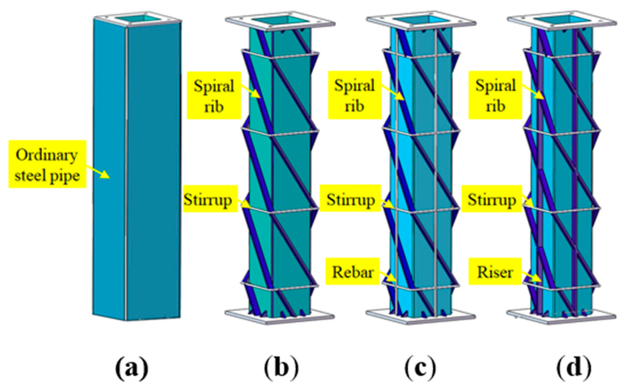
2.1. Test Processing
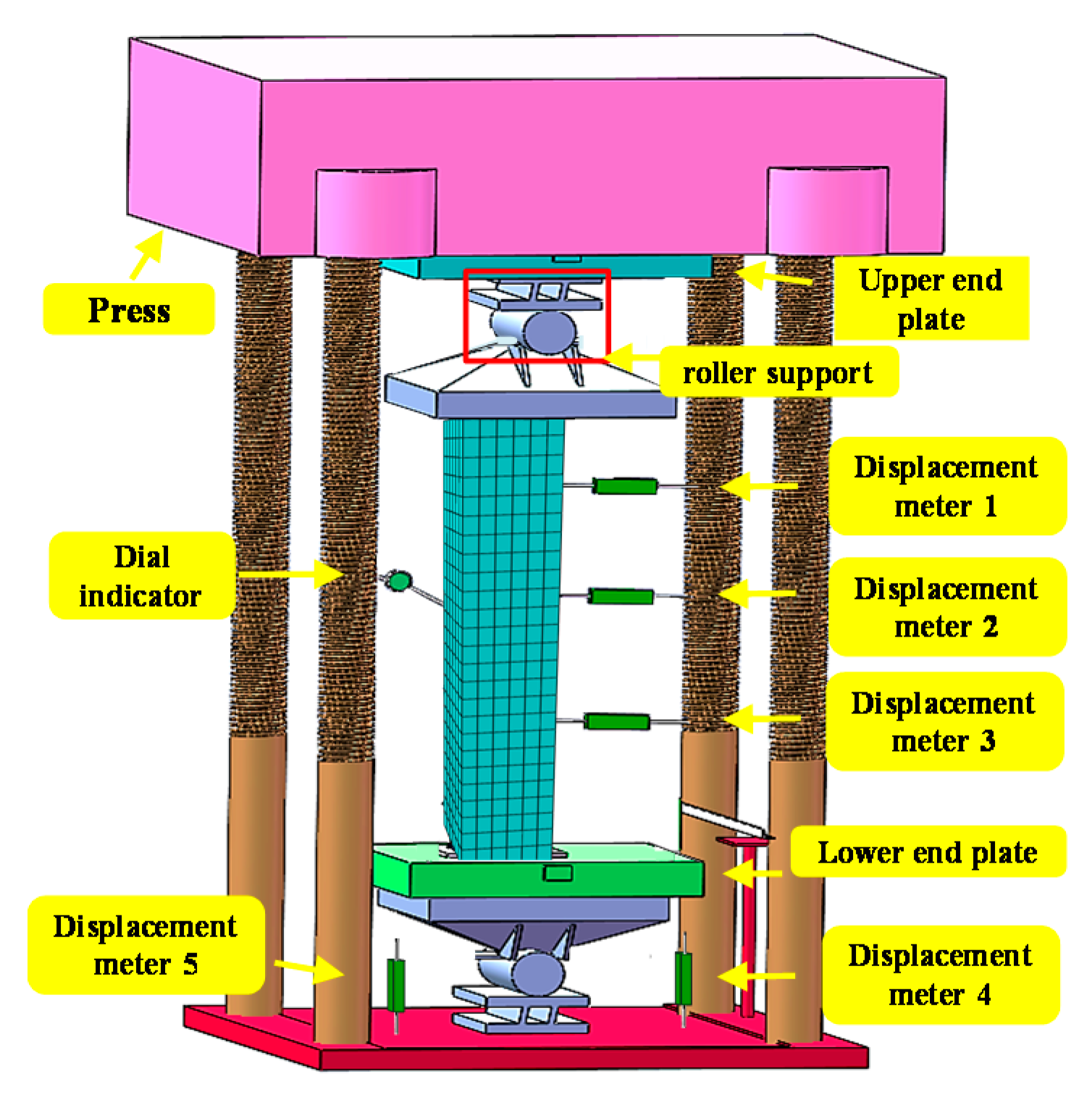
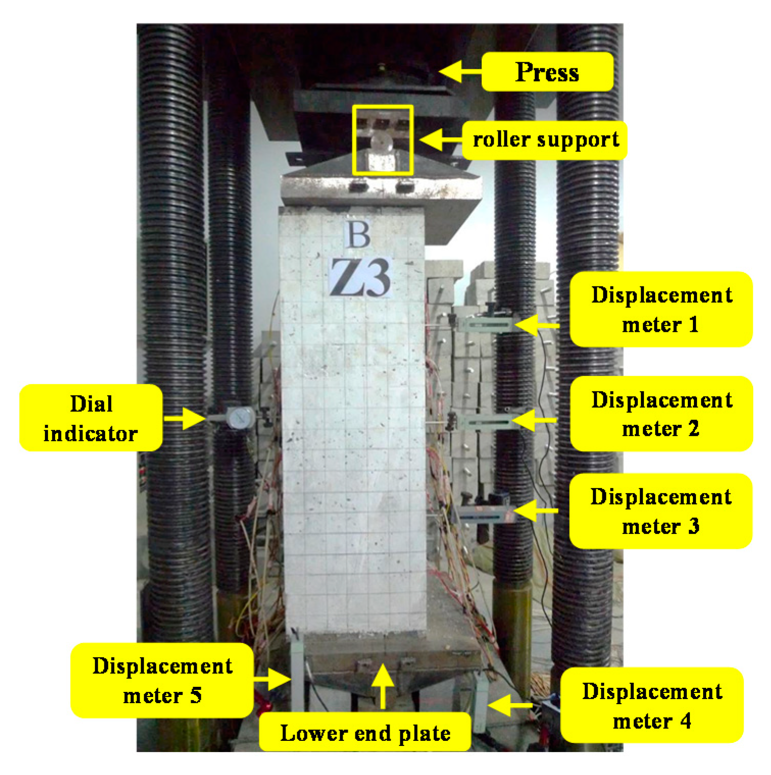
2.2. Test and Loading Scheme
3. Results and Discussion
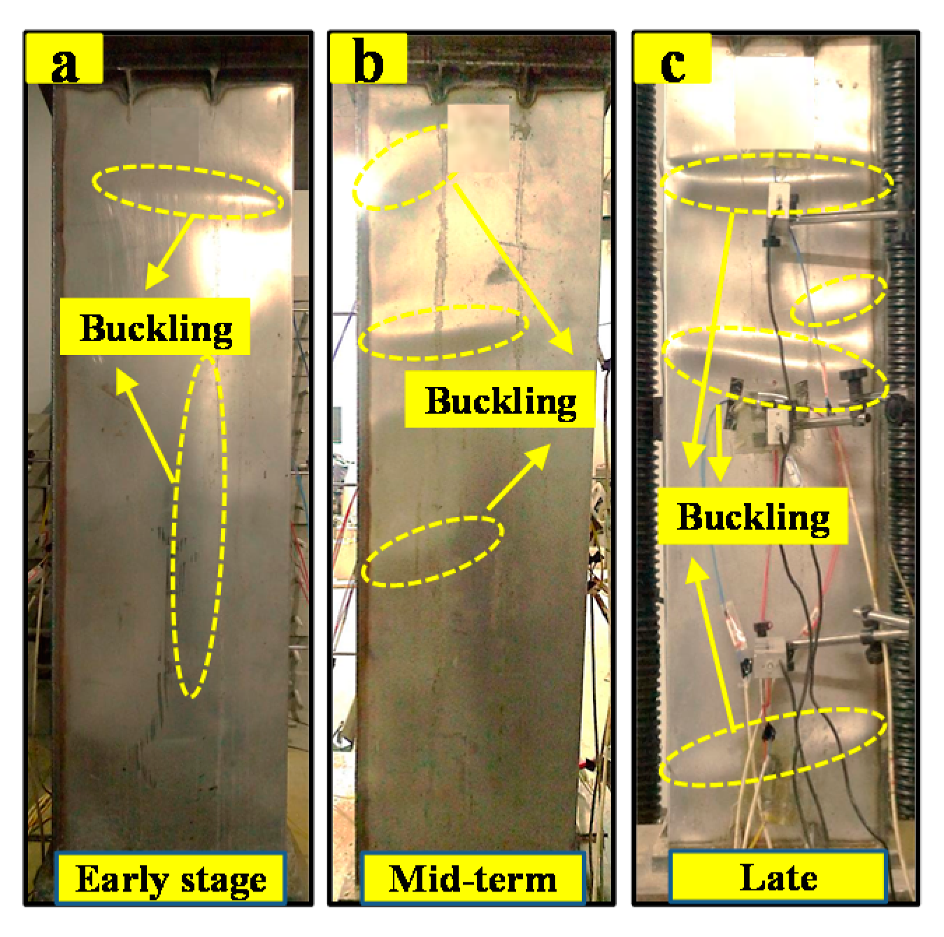
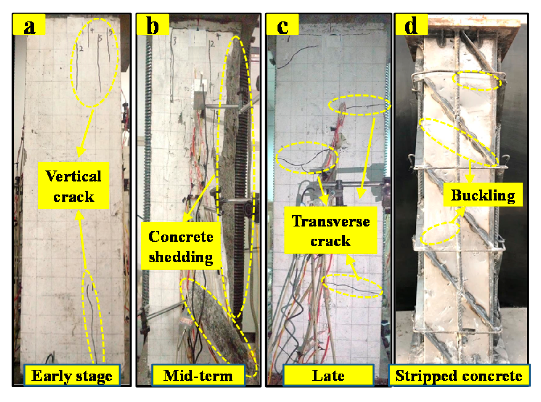
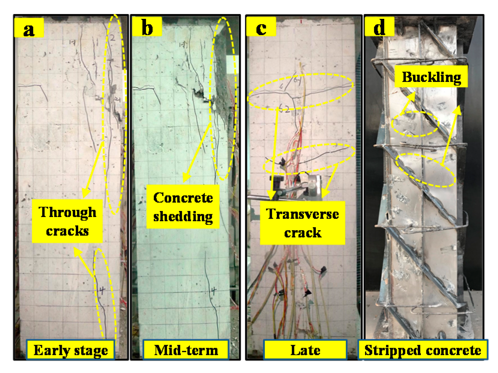
3.1. Test Procedure and Phenomena
3.2. Analysis of Test Results
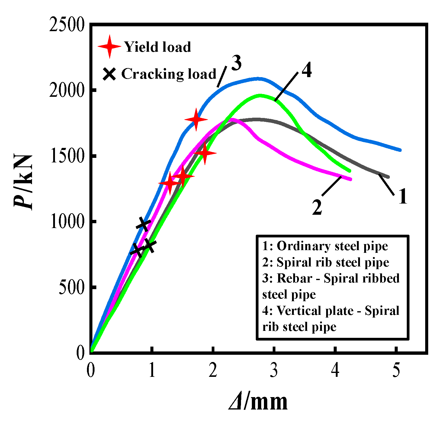
3.2.1. Load–Displacement Curves
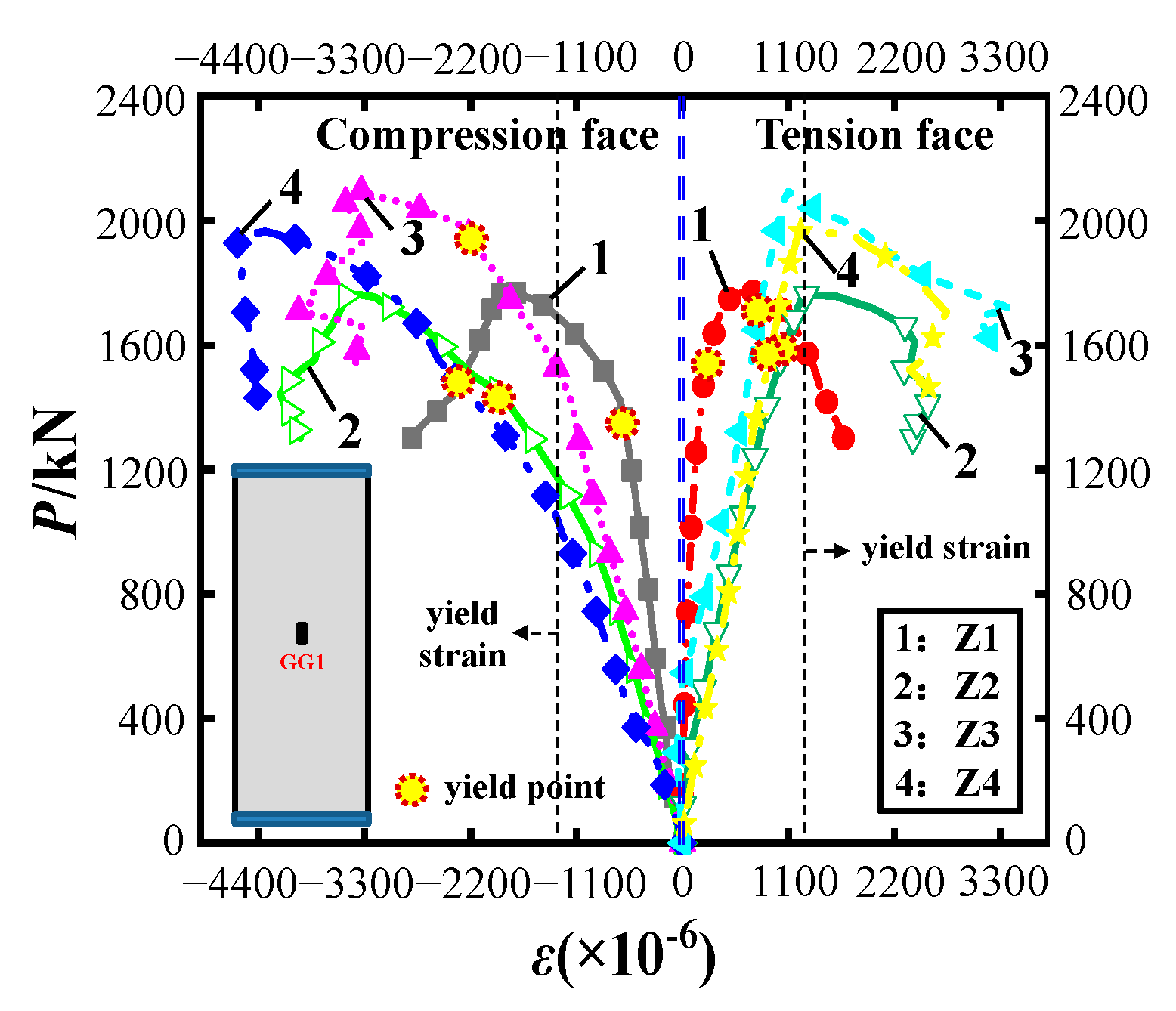
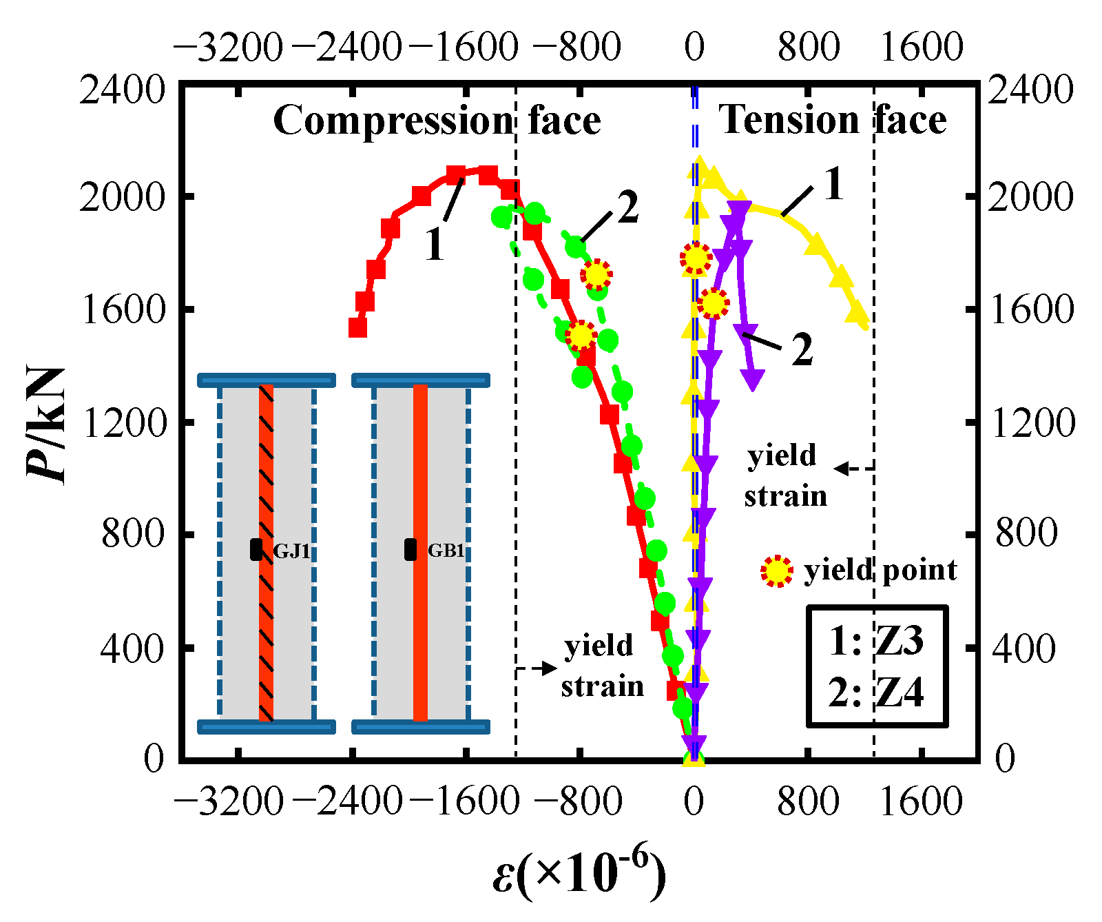
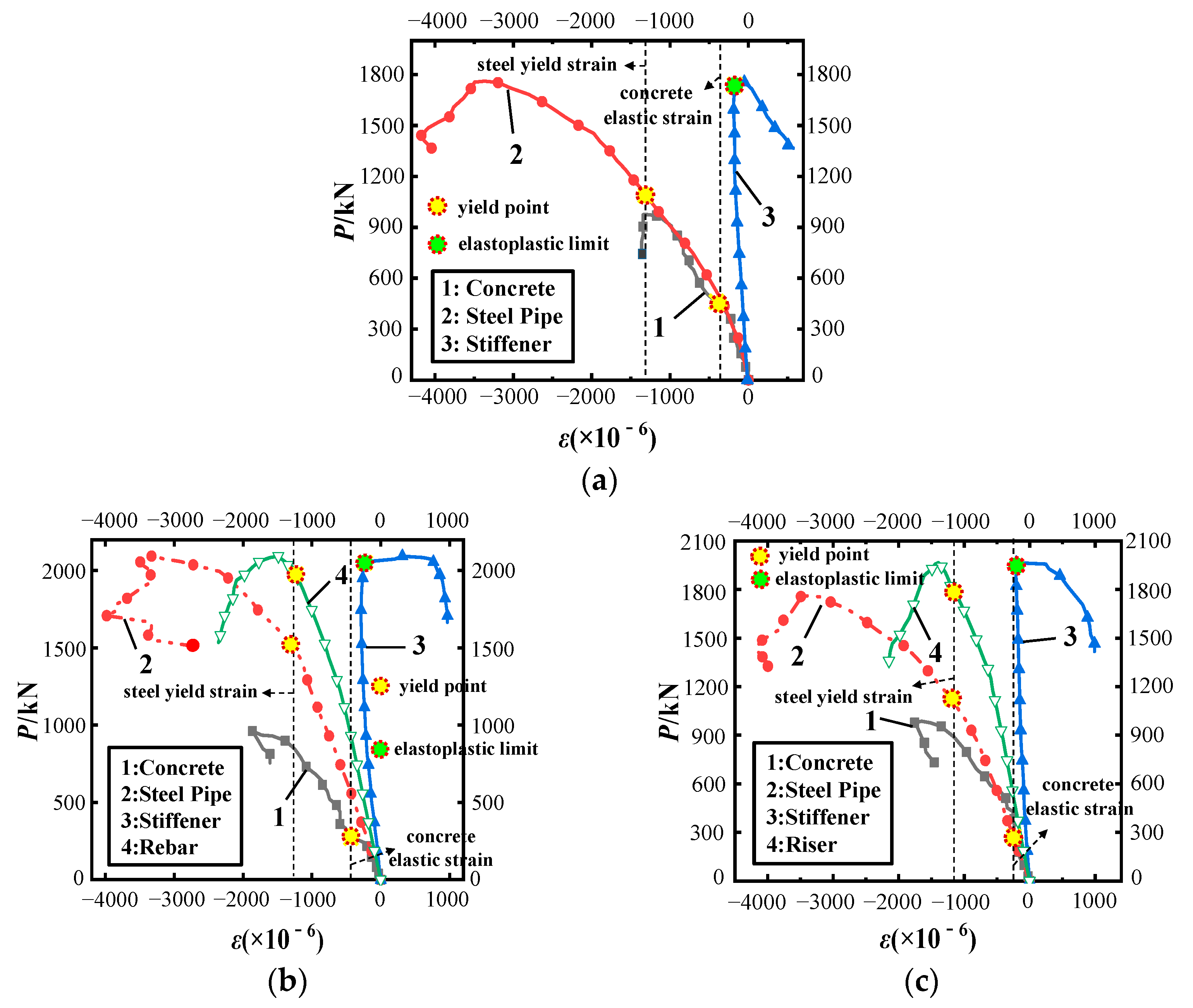
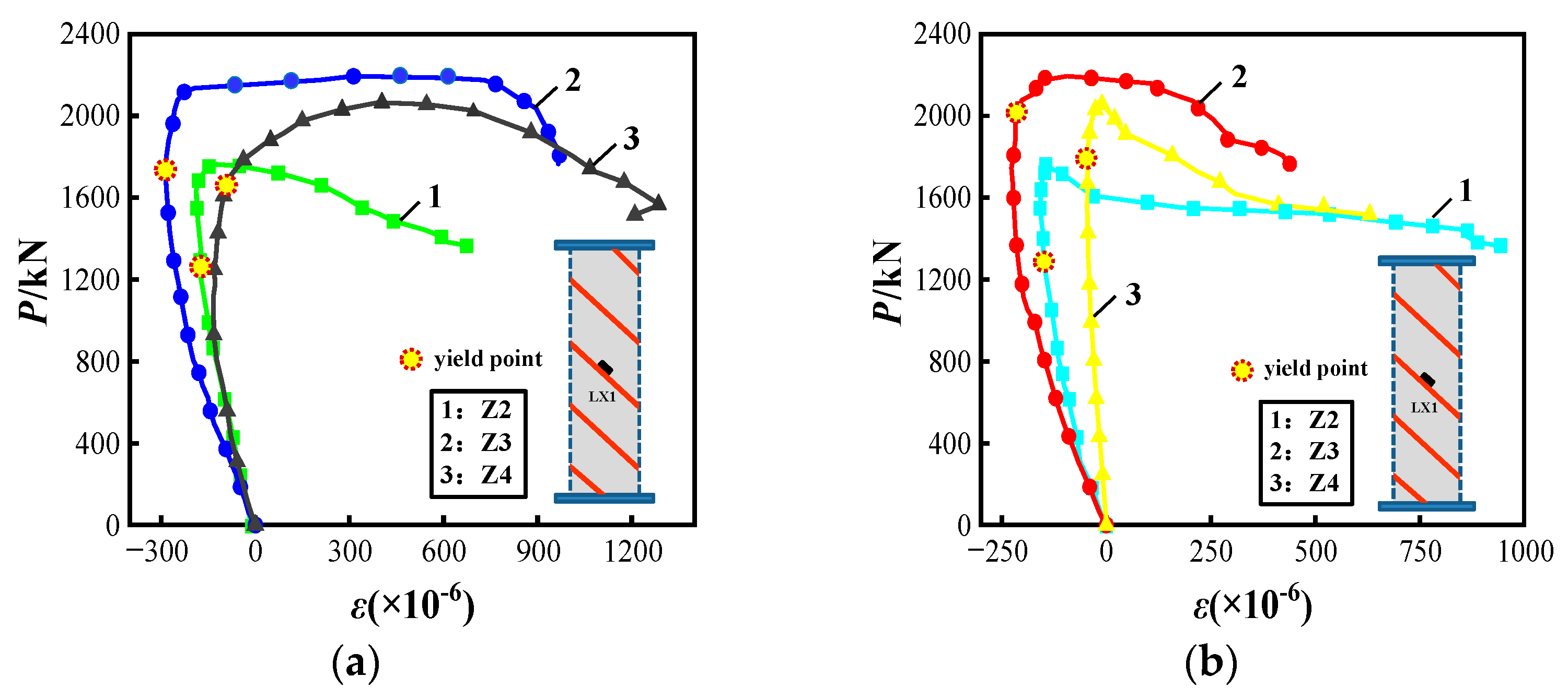
3.2.2. Load–Strain Curves
- (a)
- Steel tube strain
- (b)
- Spiral rib strain
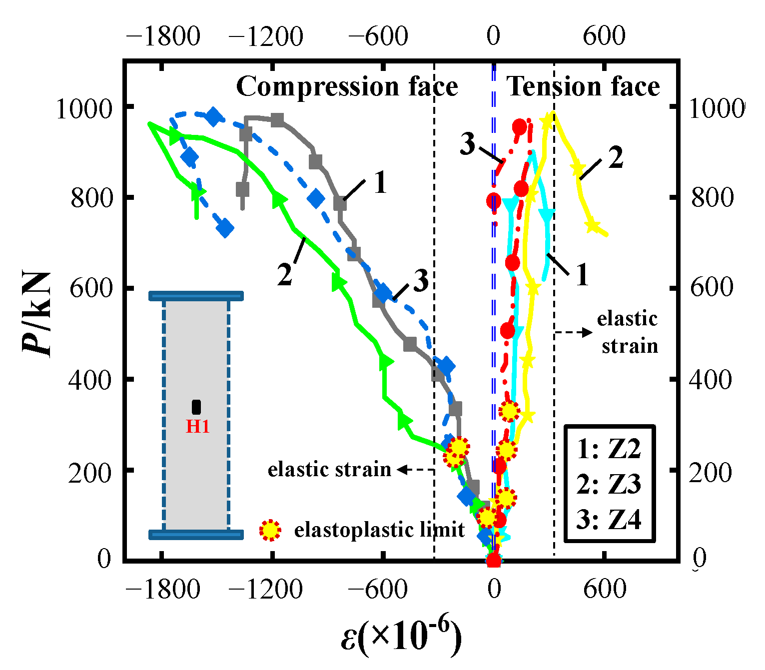
- (c)
- Strain in the steel bar and vertical plate
- (d)
- External concrete strain
3.3. Failure Mechanism
3.3.1. Failure Sequence
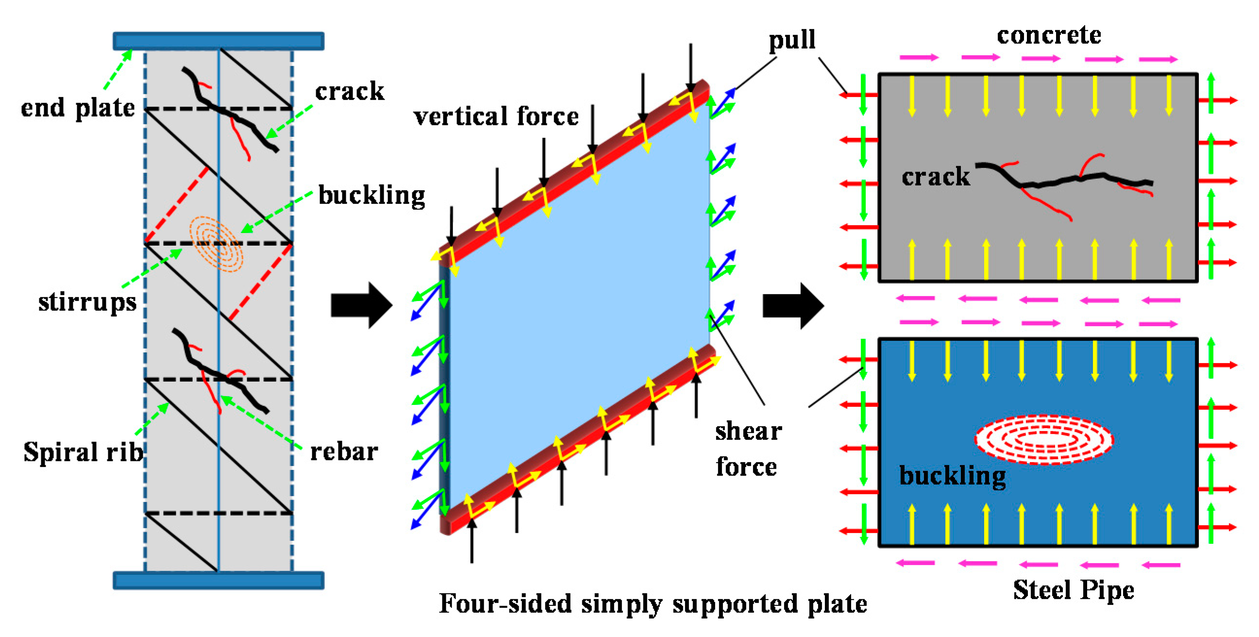
3.3.2. Stress Model
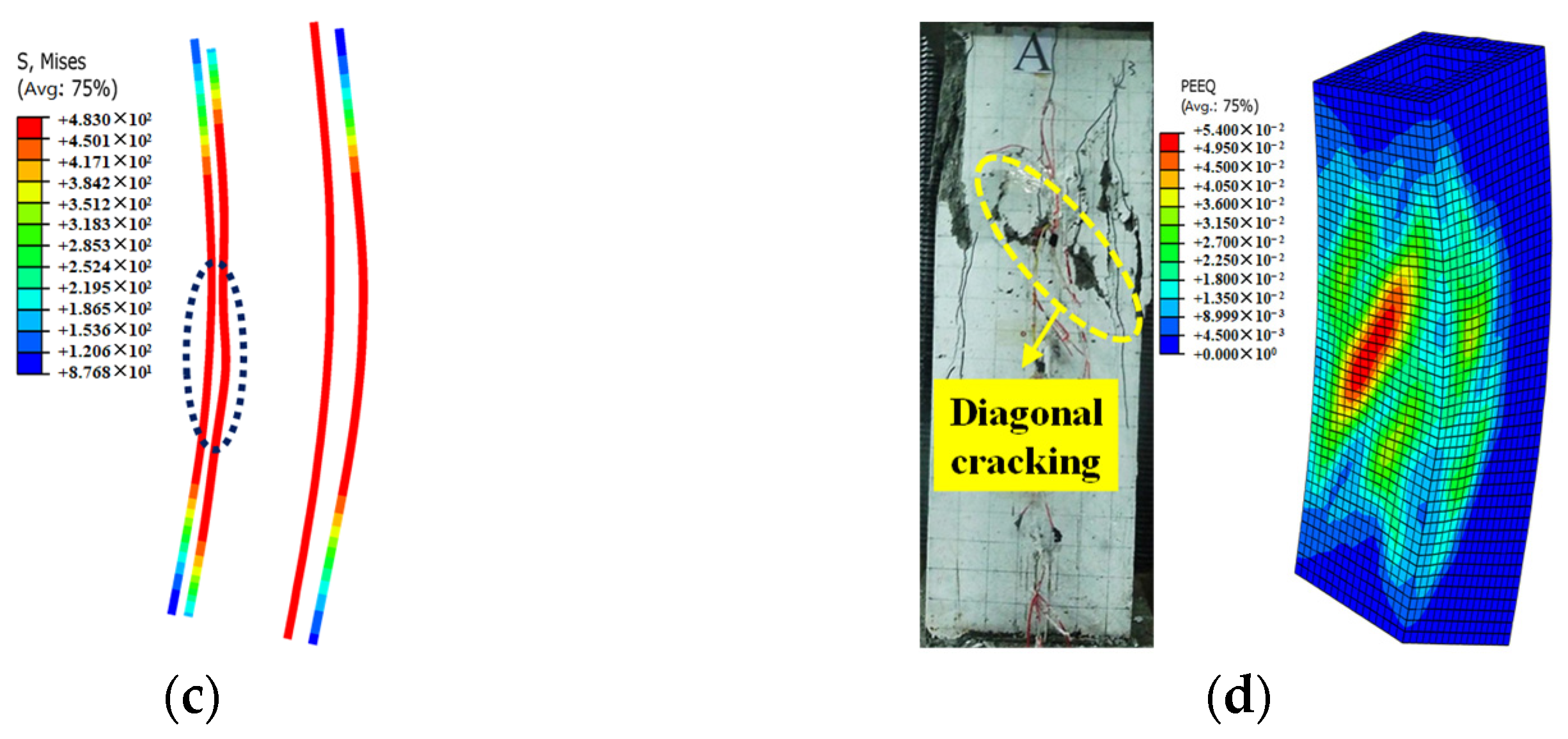
3.4. Finite Element Analysis
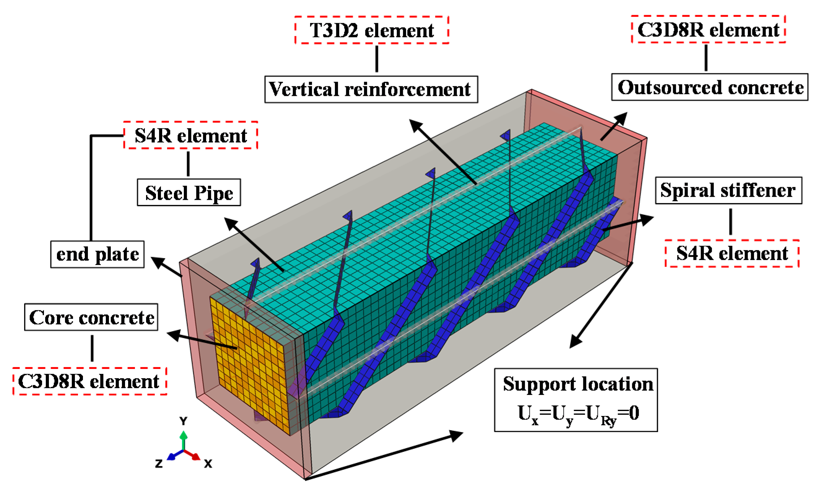
3.4.1. Finite Element Module Method
- (1)
- Material properties
- (2)
- Modeling
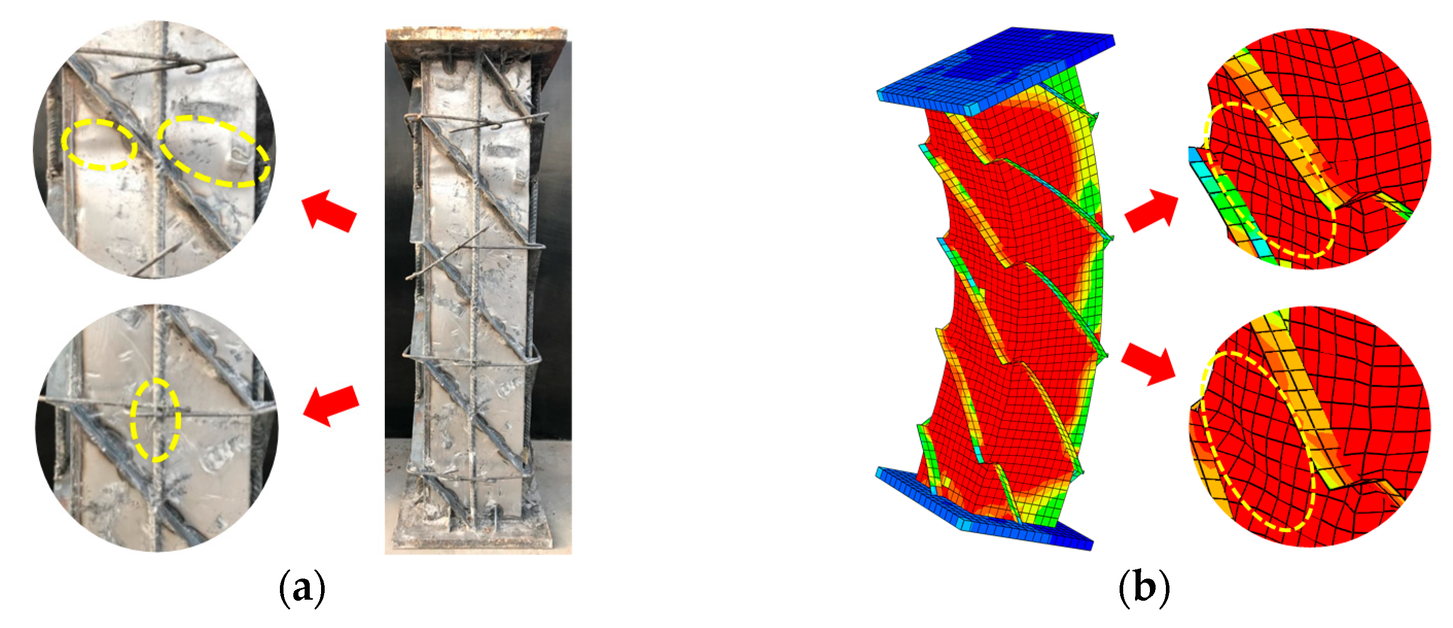
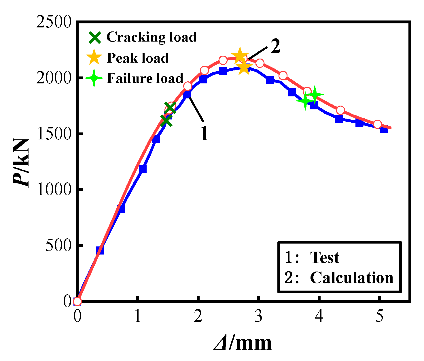
3.4.2. Validation Model
3.5. Parametric Analysis
3.5.1. Width to Thickness Ratio of the Spiral Rib
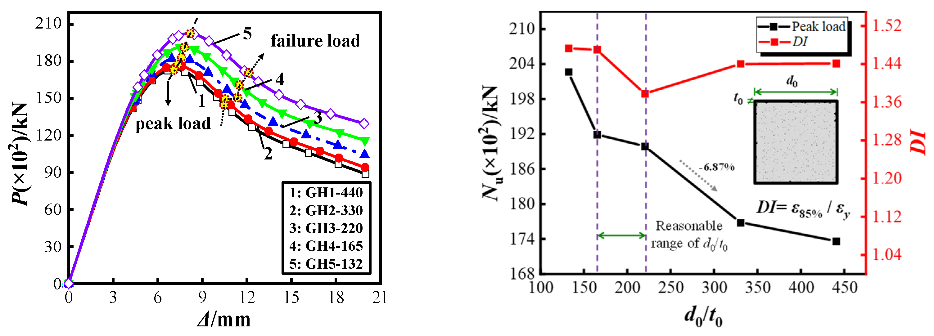
3.5.2. Width to Thickness Ratio of the Steel Tube
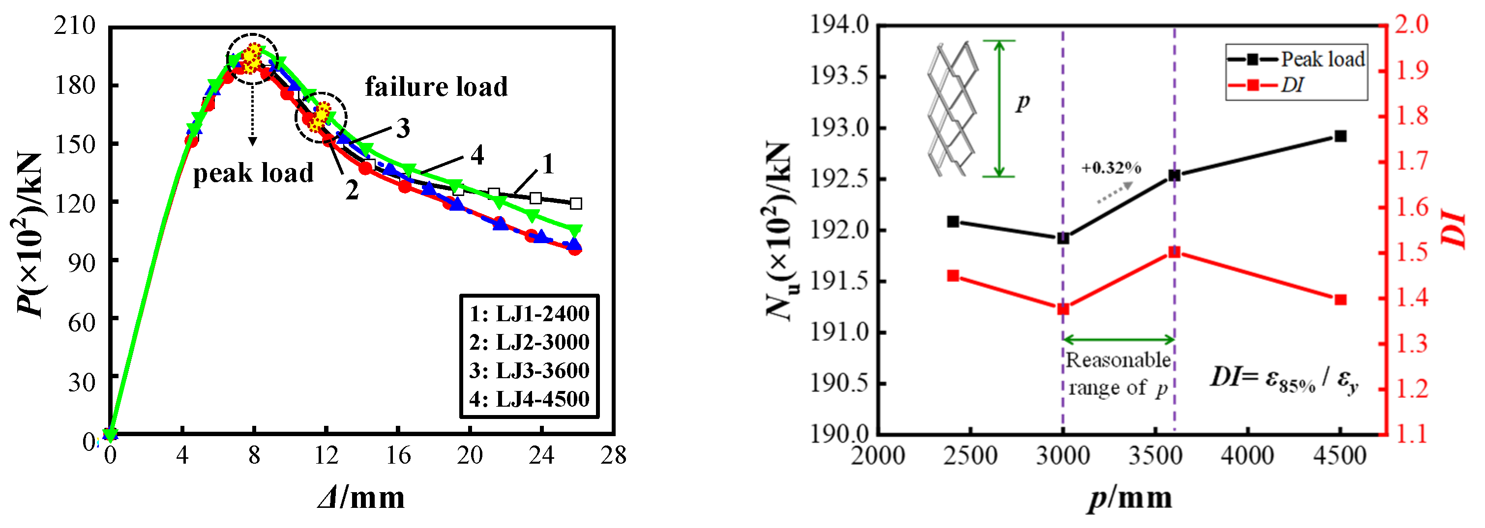
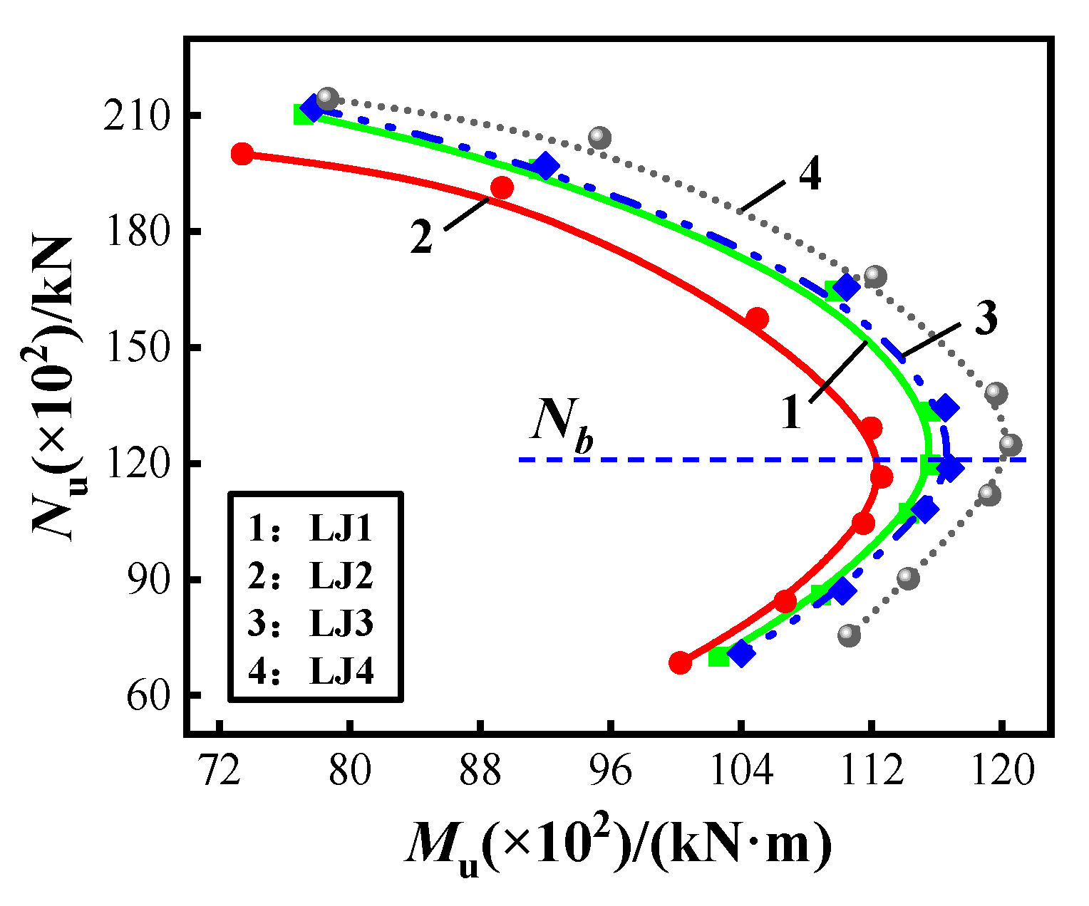
3.5.3. Pitch
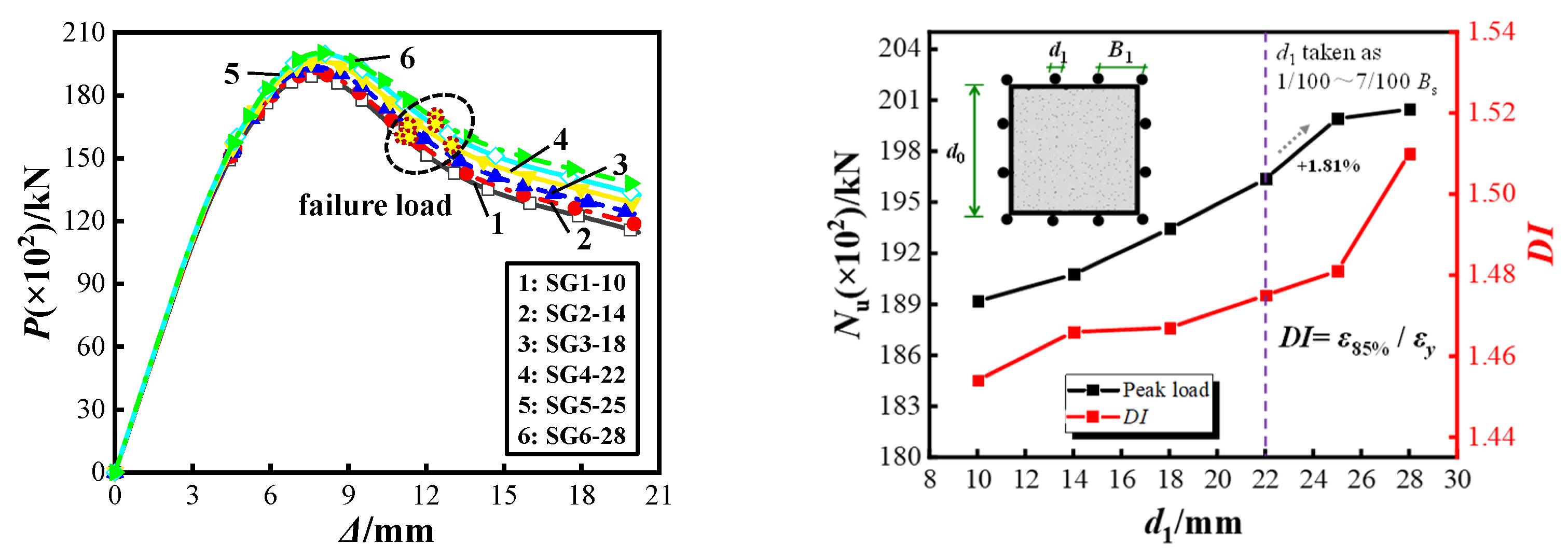
3.5.4. Vertical Steel Bar Diameter
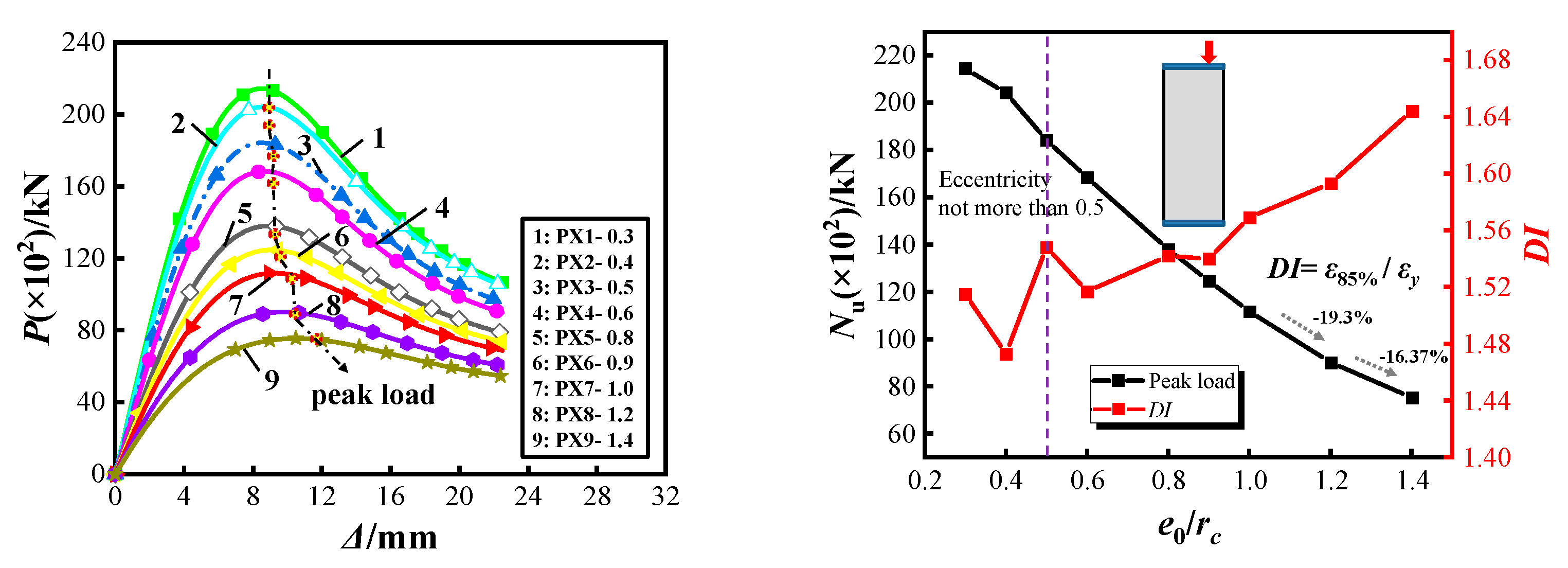
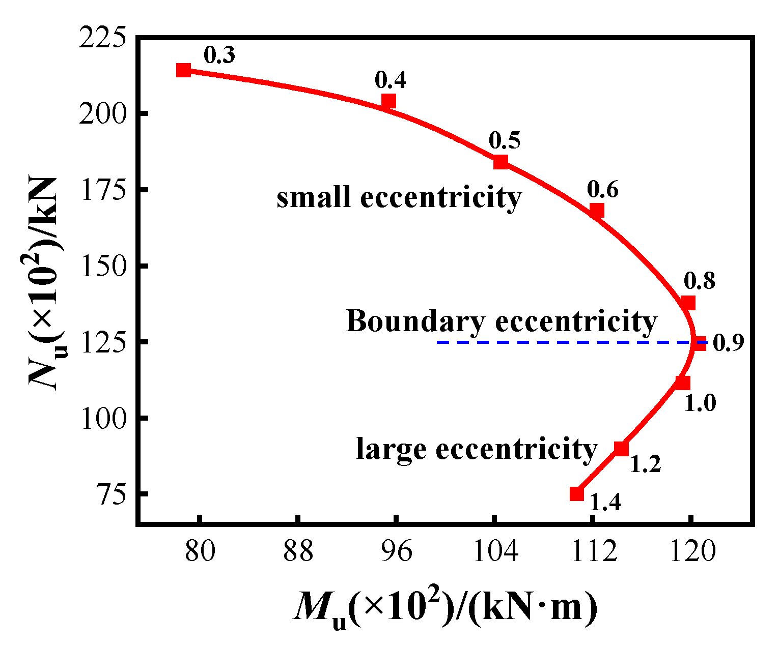
3.5.5. Eccentricity
3.6. Bearing Capacity Calculation
4. Conclusions
- (1)
- Under the constraint of spiral rib, the buckling of the steel tube is limited to occurring between the stiffeners, oblique bulging occurs, and the extent of buckling is significantly decreased. Compared with an ordinary thin-walled steel pipe concrete column (Z1), the peak bearing capacity of the spiral rib–steel constraint composite member (Z3) increased by 17.9%, the problem of fire and corrosion resistance can be better solved, and the overall performance improved. For Z2 and Z4 specimens, the deformation capacity is reduced by 10.3% and 18.6%, respectively, compared to Z1, which shows that the comprehensive performance of the specimens with a single spiral rib and the vertical plate-spiral rib is not prominent, and the overall stiffness degradation of the component is accelerated. Therefore, the external spiral rib restraint form needs to be used in conjunction with vertical reinforcement.
- (2)
- A spiral rib can improve the local flexural stiffness and enhance the thin-walled steel tube flexural capacity. As a new type of spatial restraint system, its vertical stiffness is negligible; when the member enters the elastic–plastic phase, the steel tube lateral deformation increases, before the role of the overall deformation restraint is mobilized, which is different from the role played by traditional vertical stiffening ribs.
- (3)
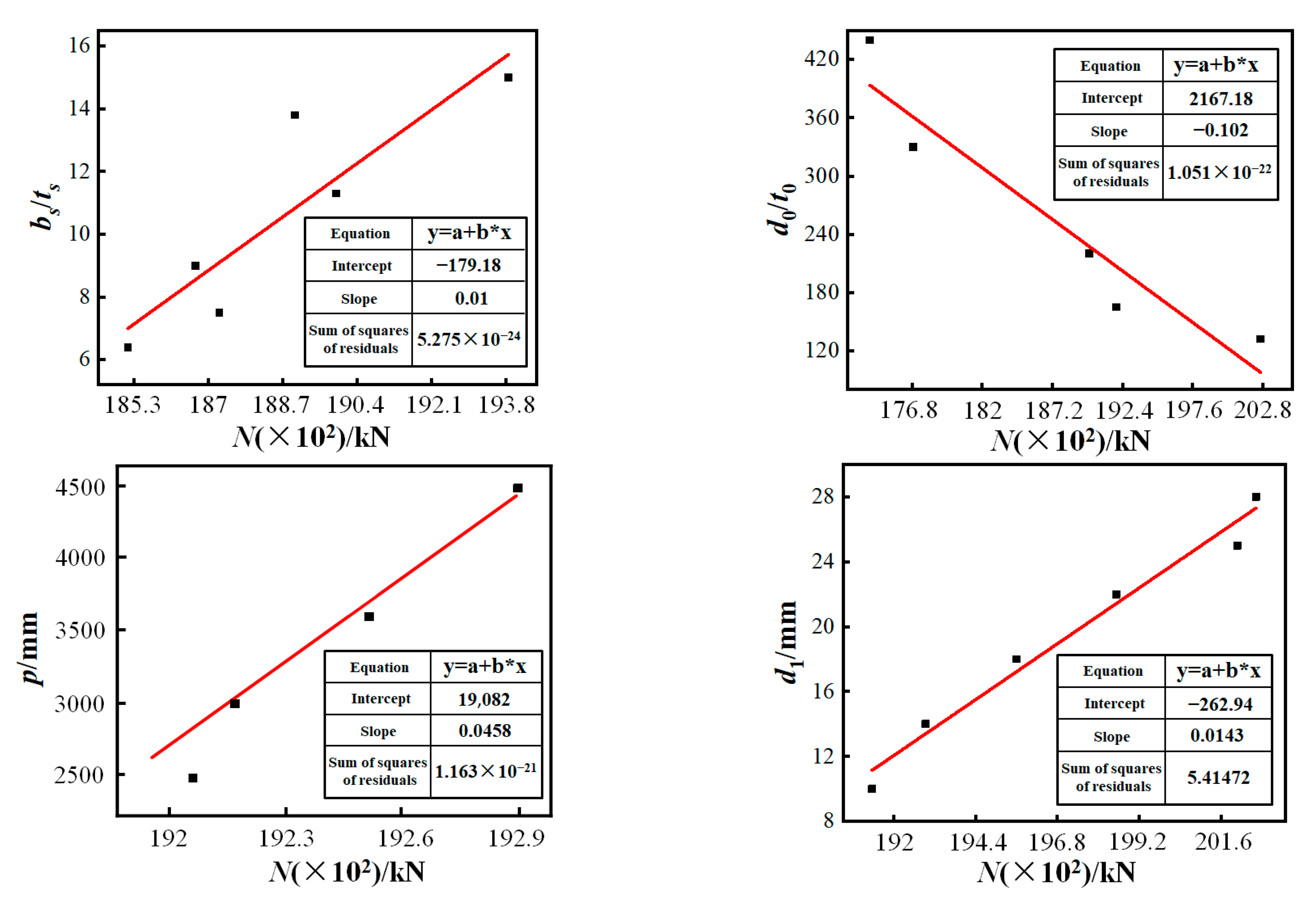
- Through a parameter analysis, the following design suggestions are obtained: the width to thickness ratio of spiral rib reinforcement should be between 11 and 15 and the spacing should be between H and 1.2H; the width to thickness ratio of the thin-walled steel pipe for this laminated member is between 165 and 220; the spacing of reinforcement as a construction component is recommended to be no more than 250 mm and the diameter of reinforcement should be 7/100 to 11/100 of the spacing B1; the eccentricity should not be greater than 0.5; through the N–M relationship, the limit of damage in compression and tension under eccentric loading is obtained as an eccentricity of about 0.9.
- (4)
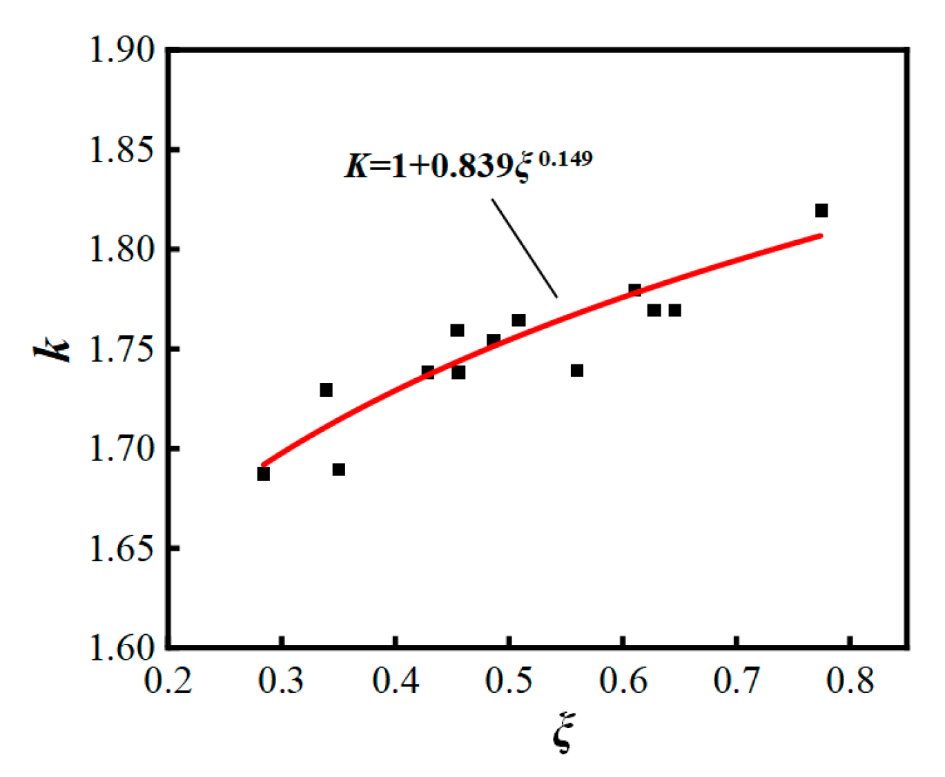
- The influences of parameters, such as the bearing capacity influence coefficient β of the spirally ribbed steel pipe, reinforcement factor for core concrete under hoop restraint k, and the hoop coefficient ξ of the spirally ribbed steel pipe were determined, and the method of calculating the eccentric compressive ultimate bearing capacity of this new composite member was proposed, which can provide a basis for its engineering design.
Author Contributions
Funding
Institutional Review Board Statement
Informed Consent Statement
Data Availability Statement
Acknowledgments
Conflicts of Interest
Abbreviations
| H | Component height |
| d0/t0 | Tube edge length and thickness |
| bs × ts | Spiral rib width and thickness |
| αs | Horizontal spacing of spiral ribs |
| bs | Longitudinal spacing of spiral ribs |
| bp × tp | Vertical plate width and thickness |
| d1 | Diameter of vertical reinforcement |
| p | Pitch |
| δ | Elongation |
| e0/rc | Load eccentricity |
| fy | Steel yield strength |
| fy1 | Reinforcement yield strength |
| fu | Ultimate strength of steel |
| fy/fu | Yield–strength ratio |
| fcu,k | Standard value of compressive strength of concrete cube |
| fck | Standard value of axial compressive strength of concrete |
| fc | Design value of axial compressive strength of concrete |
| Es | Elastic modulus of steel |
| Ec | Elastic modulus of concrete |
| Pcr | Cracking load |
| Py | Yield load |
| Pmax | Peak load |
| Pu | Limit load |
| Pcr/Pu | Cracking load ratio |
| Δy | Yield displacement |
| Δmax | Peak displacement |
| Δu | Limit displacement |
| Δu/Δy | Deformation capacity |
| Δu/Δmax | Security reserve |
| σc | Concrete stress |
| σ0 | Peak stress of concrete |
| εa | Steel tube strain |
| εc | Concrete strain |
| ε0 | Peak strain of concrete |
| εcu | Ultimate compressive strain of normal section concrete |
| η | Strain calculation parameters |
| ε1 | Steel yield strain |
| ε2 | Plastic strain of steel |
| ε3 | Flow plastic strain of steel |
| α1 | Local stability enhancement coefficient of steel pipe |
| α2 | Strength reduction coefficient of concrete |
| δ1 | Comprehensive influence coefficient of strength of thin-wall composite column steel pipe |
| k | Reinforcement coefficient of core concrete under hoop confinement |
| φe | Eccentricity impact coefficient |
| β | Influence coefficient of bearing capacity of spiral rib steel tube |
| β0 | Strain curve drop correction factor |
| ξ | Constraint coefficient of spiral rib steel pipe |
| ξ1 | The hoop coefficient of ordinary steel pipe |
| ζ | Spiral rib restraint factor |
| Aa | Steel pipe cross-sectional area |
| Ac | Full concrete cross-sectional area |
| As | Cross-sectional area of single spiral rib |
| As1 | Rebar cross-sectional area |
| As2 | Cross-sectional area of spiral ribbed steel pipe |
| Ac1 | External concrete cross-sectional area |
| Ac2 | Core concrete cross-sectional area |
| N1 | Vertical steel bearing capacity |
| N2 | External concrete bearing capacity |
| N3 | Spiral ribbed steel pipe bearing capacity |
| N4 | Core concrete bearing capacity |
| Nu | Axial compression ultimate bearing capacity |
| Ne | Bias ultimate bearing capacity |
References
- Heman Aiswarya, M.; Roshni, K.G. Numerical Study on Concrete-Filled Steel Tubes with Diagonal Binding Ribs and Longitudinal Stiffeners. Recent Adv. Comput. Exp. Mech. 2022, II, 1524. [Google Scholar] [CrossRef]
- O’Shea, M.D.; Bridge, R.Q. Local buckling of thin-walled circular steel sections with or without internal restraint. J. Constr. Steel Res. 1997, 41, 137–157. [Google Scholar] [CrossRef]
- Thomas, J.; Sandeep, T.N. Experimental study on circular CFST short columns with intermittently welded stiffeners. Steel Compos. Struct. 2018, 29, 659–667. [Google Scholar] [CrossRef]
- Ansa, K.P.; Keerthi, S. Analysis of the Concrete Filled Steel Tubes with Diagonal Ribs. In Proceedings of SECON 2020 Structural Engineering and Construction Management; Springer: Cham, Switzerland, 2020; pp. 719–734. [Google Scholar] [CrossRef]
- Zhou, Z.; Gan, D.; Zhou, X.H. Improved Composite Effect of Square Concrete-Filled Steel Tubes with Diagonal Binding Ribs. J. Struct. Eng. 2019, 145, 04019112. [Google Scholar] [CrossRef]
- Chybiński, M.; Garstecki, A. Diagonal Versus Orthogonal Ribs in Stability of Steel I Beams. Procedia Eng. 2017, 172, 172–177. [Google Scholar] [CrossRef]
- Huang, H.; Zhang, A.G.; Li, Y.; Chen, M.C. Experimental research and finite element analysis on mechanical performance of concrete-filled stiffened square steel tubular stub columns subjected to axial compression. J. Build. Struct. 2011, 32, 75–82. [Google Scholar] [CrossRef]
- Huang, B.T.; Dai, J.G.; Weng, K.F.; Zhu, J.X.; Shah, S.P. Flexural Performance of UHPC–Concrete–ECC Composite Member Reinforced with Perforated Steel Plates. J. Struct. Eng. 2021, 147, 04021065. [Google Scholar] [CrossRef]
- Maiorana, E.; Tetougueni, C.D.; Zampieri, P.; Pellegrino, C. Experimental and numerical investigations on slender panels with holes under symmetrical localised loads. Eng. Struct. 2021, 228, 111323. [Google Scholar] [CrossRef]
- Wei, Y.; Wang, Z.Y.; Chen, S.; Zhao, K.; Zheng, K. Structural behavior of prefabricated bamboo-lightweight concrete composite beams with perforated steel plate connectors. Arch. Civ. Mech. Eng. 2021, 21, 15. [Google Scholar] [CrossRef]
- Pellegrino, C.; Maiorana, E.; Modena, C. Linear and non-linear behaviour of steel plates with circular and rectangular holes under shear loading. Thin-Walled Struct. 2008, 47, 607–616. [Google Scholar] [CrossRef]
- Hamidian, M.R.; Jumaat, M.Z.; Alengaram, U.J.; Sulong, N.R.; Shafigh, P. Pitch spacing effect on the axial compressive behaviour of spirally reinforced concrete-filled steel tube (SRCFT). Thin-Walled Struct. 2016, 100, 213–223. [Google Scholar] [CrossRef]
- Ibrahim, A.; Askar, H.S.; El, Z.M.E. Torsional Behavior of Solid and Hollow Concrete Beams Reinforced with Inclined Spirals. J. King Saud Univ. Eng. Sci. 2020, 34, 309–321. [Google Scholar] [CrossRef]
- Katkhuda, H.N.; Shatarat, N.K.; Al-Rakhameen, A. Improving the Torsional Capacity of Reinforced Concrete Beams with Spiral Reinforcement. Int. J. Civ. Struct. Eng. 2019, 8, 113–118. [Google Scholar] [CrossRef]
- Gunawardena, Y.; Aslani, F. Behaviour and design of concrete-filled spiral-welded stainless-steel tube short columns under concentric and eccentric axial compression loading. J. Constr. Steel Res. 2019, 158, 522–546. [Google Scholar] [CrossRef]
- Wu, B.; Zhang, Q.; Chen, G.M. Compressive behavior of thin-walled circular steel tubular columns filled with steel stirrup-reinforced compound concrete. Eng. Struct. 2018, 170, 178–195. [Google Scholar] [CrossRef]
- Zhang, Y.F.; Wang, Q.; Cai, C.S.; Yan, C. Calculation on Ultimate Axial Bearing Capacity of Concrete-Filled Square Steel Tubular Column with Spiral Stirrups. J. Comput. Theor. Nanosci. 2016, 13, 1422–1425. [Google Scholar] [CrossRef]
- Xue, J.Y.; Zhao, X.B.; Ke, X.J.; Zhang, X.; Zhang, F.; Zhang, P. Experimental and numerical investigation of high-strength concrete encased steel columns with rectangular-spiral stirrupss. J. Build. Eng. 2020, 32, 101518. [Google Scholar] [CrossRef]
- Chen, Z.P.; Ke, X.J.; Chen, Y.L. Experimental study on seismic behavior of steel reinforced high-strength concrete columns confined by square spiral stirrups. J. Chin. Civ. Eng. J. 2015, 48, 41–49, +59. [Google Scholar]
- Inai, E.; Mukai, A.; Kai, M.; Tokinoya, H.; Fukumoto, T.; Mori, K. Behavior of Concrete-Filled Steel Tube Beam Columns. J. Struct. Eng. 2004, 130, 189–202. [Google Scholar] [CrossRef]
- Wu, Z.M.; Yang, S.T.; Zheng, J.J.; Hu, X. Analytical solution for the pull-out response of FRP rods embedded in steel tubes filled with cement grout. Mater. Struct. 2010, 43, 597–609. [Google Scholar] [CrossRef] [Green Version]
- Zhang, Y.C.; Chen, Y. Experimental study and finite element analysis of square stub columns with straight ribs of concrete-filled thin-walled steel tube. J. Build. Struct. 2006, 27, 23–29. [Google Scholar] [CrossRef]
- Le, K.B.; Cao, V.V. Numerical Study of Circular Concrete Filled Steel Tubes Subjected to Pure Torsion. Buildings 2021, 11, 397. [Google Scholar] [CrossRef]
- Islam, M.M.; Ali, R.B.; Begum, M.; Rahman, S. Experimental Study of Square Concrete-Filled Welded Cold-Formed Steel Columns Under Concentric Loading. Arab. J. Sci. Eng. 2020, 46, 4225–4237. [Google Scholar] [CrossRef]
- Ananthi, G.; Roy, K.; Lim, J. Experimental and numerical investigations on axial strength of back-to-back built-up cold-formed steel angle columns. Steel Compos. Struct. 2019, 31, 601–615. [Google Scholar] [CrossRef]
- Wei, J.G.; Luo, X.; Lai, Z.C.; Varma, A.H. Experimental Behavior and Design of High-Strength Circular Concrete-Filled Steel Tube Short Columns. J. Struct. Eng. 2020, 146, 04019184. [Google Scholar] [CrossRef]
- Hernández-Figueirido, D.; Romero, M.L.; Bonet, J.L.; Montalvá, J.M. Influence of Slenderness on High-Strength Rectangular Concrete-Filled Tubular Columns with Axial Load and Nonconstant Bending Moment. J. Struct. Eng. 2012, 138, 1436–1445. [Google Scholar] [CrossRef]
- Wang, J.; Sun, Q.; Li, J. Experimental study on seismic behavior of high-strength circular concrete-filled thin-walled steel tubular columns. Eng. Struct. 2019, 182, 403–415. [Google Scholar] [CrossRef]
- Zhou, S.; Sun, Q.; Wu, X. Impact of D/t ratio on circular concrete-filled high-strength steel tubular stub columns under axial compression. Thin-Walled Struct. 2018, 132, 461–474. [Google Scholar] [CrossRef]
- Child, J.A.; Bowry, M.W.; Knowles, J.P. Abnormality of red-cell diameter-thickness ratio: Findings in iron-deficiency anaemia. Br. J. Haematol. 1970, 19, 251–255. [Google Scholar] [CrossRef] [PubMed]
- Ci, J.C.; Chen, S.C.; Jia, H.; Yan, W.; Song, T.; Kim, K.-S. Axial compression performance analysis and bearing capacity calculation on square concrete-filled double-tube short columns. Mar. Struct. 2020, 72, 102775. [Google Scholar] [CrossRef]
- Zhou, C.Y.; Yang, J.R.; Jiang, W.W. Transverse Ribs Affect the Stability of Steel-Concrete Composite Box Beams. Appl. Mech. Mater. 2014, 3308, 1663–1667. [Google Scholar] [CrossRef]
- Higaki, S.; Nishida, H.; Koike, Y.; Sasada, M.; Tanaka, T. Effect of transverse ribs on axial displacement of rebars in bending. Procedia Manuf. 2020, 50, 253–256. [Google Scholar] [CrossRef]
- Hasan, H.G.; Ekmekyapar, T. Mechanical Performance of Stiffened Concrete Filled Double Skin Steel Tubular Stub Columns under Axial Compression. KSCE J. Civ. Eng. 2019, 23, 2281–2292. [Google Scholar] [CrossRef]
- Raza, A.; Ali, B.; Nawaz, M.A.; Ahmed, I. Structural performance of FRP-RC compression members wrapped with FRP composites. Structures 2020, 27, 1693–1709. [Google Scholar] [CrossRef]
- Lee, C.H.; Kang Thomas, H.K.; Kim, J.W.; Song, J.-K.; Kim, S. Seismic Performance of Concrete-Filled Tube Column-Reinforced Concrete Slab Connections with Shear Reinforcement. ACI Struct. J. 2019, 116, 233–244. [Google Scholar] [CrossRef]
- Amini, A.B.; Palangsaraee, S.M. Effect of Rebar on Ductility of Moment-resisting Frame with Concrete-filled Tube Column. Open Civ. Eng. J. 2019, 13, 172–181. [Google Scholar] [CrossRef]
- Park, Y.M.; Hwang, W.S.; Yoon, T.Y.; Hwang, M.-O. A new base plate system using deformed reinforcing bars for concrete filled tubular column. Steel Compos. Struct. 2005, 5, 375–394. [Google Scholar] [CrossRef]
- Wang, H.J.; Lu, C.C.; Wei, H. Seismic analysis for concrete filled steel tube column row shear wall with steel plate energy dissipation bond. J. Shenyang Univ. Technol. 2016, 38, 228–234. [Google Scholar] [CrossRef]
- Han, L.H.; Zhong, T.; Liu, W. Concrete filled steel tubular structures from theory to practice. J. Fuzhou Univ. (Nat. Sci. Ed.) 2001, 29, 24–34. [Google Scholar] [CrossRef]
- Smoljanović, H.; Balić, I.; Munjiza, A.; Hristovski, V. Rotation-Free Based Numerical Model for Nonlinear Analysis of Thin Shells. Buildings 2021, 11, 657. [Google Scholar] [CrossRef]
- Wang, Z.S.; Li, Y.K.; Wei, J.; Li, Q.; Shen, M.P. Hysteretic behavior and numerical analysis of thin-walled concrete-encapsulated steel tubular composite column with spiral ribs. Chin. J. Appl. Mech. 2021, 38, 2298–2305. [Google Scholar] [CrossRef]


| Specimen Number | Constraint Form | H/mm | d1/mm | d0 × t0 | bs × ts | bp × tp |
|---|---|---|---|---|---|---|
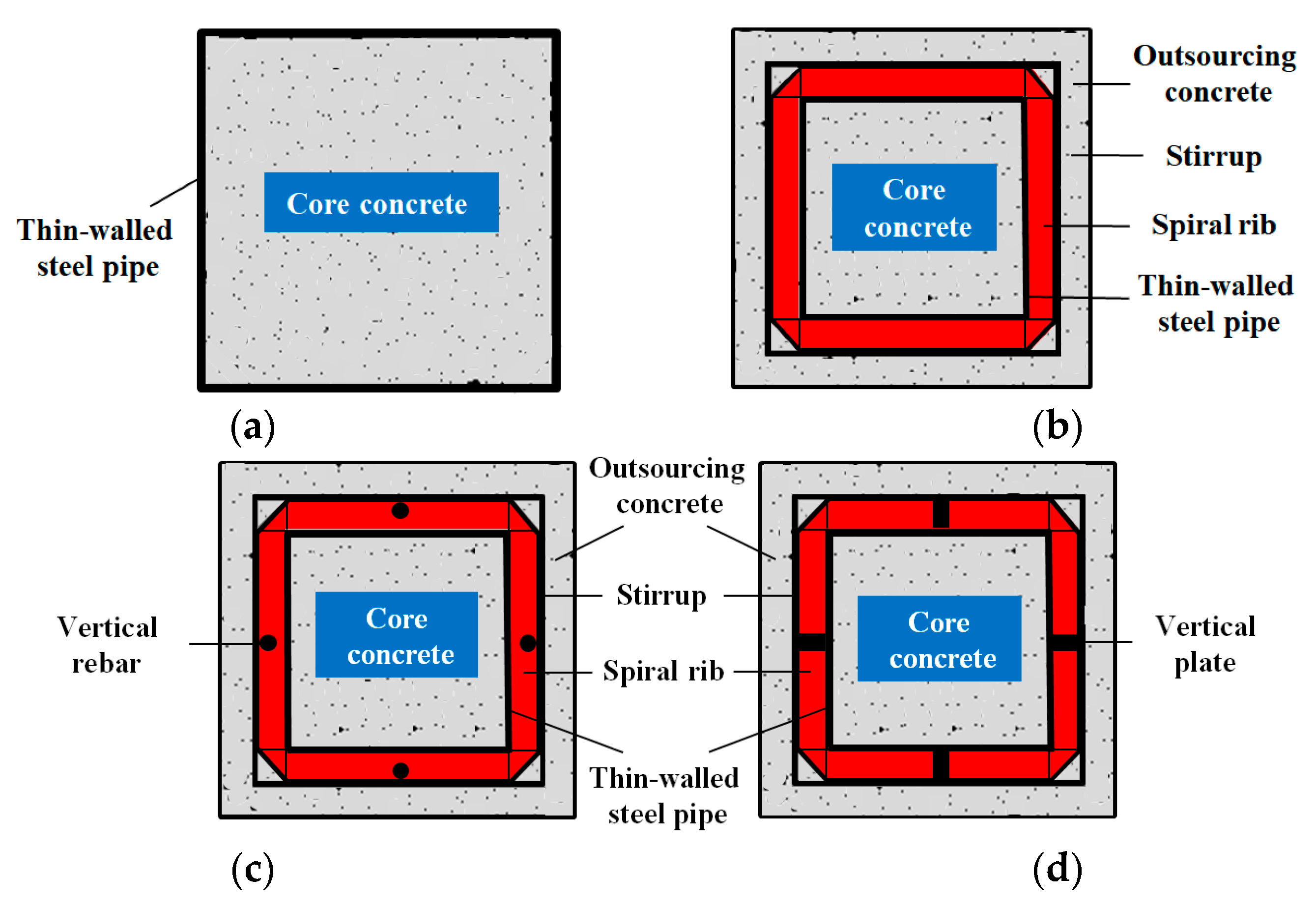
| Z1 | None | 1000 | - | 340 × 1 | - | - |
| Z2 | Spiral rib | 1000 | - | 220 × 1 | 30 × 3 | - |
| Z3 | Spiral rib rebar | 1000 | 14 | 220 × 1 | 30 × 3 | - |
| Z4 | Spiral rib riser | 1000 | - | 220 × 1 | 30 × 3 | 30 × 5 |
| Material | Material Property | fy/MPa | fu/MPa | fy/fu | Es/105 MPa | δ% |
|---|---|---|---|---|---|---|
| Steel Pipe (1.0 mm) | Q235-B | 278.70 | 388.93 | 0.72 | 2.06 | 27.3 |
| Stiffener (3.0 mm) | Q235-B | 256.94 | 363.79 | 0.71 | 2.03 | 25.7 |
| Riser (5.0 mm) | Q235-B | 252.65 | 359.26 | 0.70 | 2.02 | 22.7 |
| Rebar (Φ14 mm) | HRB400 | 462.95 | 625.30 | 0.74 | 1.96 | 24.6 |
| Concrete Strength Grade | fcu,k/MPa | fck/MPa | fc/MPa | Ec/GPa |
|---|---|---|---|---|
| C30 | 36.2 | 24.2 | 17.29 | 24.5 |
| Test Piece | Pcr/kN | Pcr/Pu | Py/kN | Δy/mm | Pmax/kN | Δmax/mm | Pu/kN | Δu/mm | Δu/Δy | Δu/Δmax |
|---|---|---|---|---|---|---|---|---|---|---|
| Z1 | - | - | 1344.9 | 2.04 | 1775.1 | 2.56 | 1508.8 | 4.16 | 2.04 | 1.625 |
| Z2 | 780 | 0.52 | 1303.6 | 1.83 | 1763.4 | 2.29 | 1498.9 | 3.35 | 1.83 | 1.463 |
| Z3 | 970 | 0.55 | 1765.7 | 1.98 | 2093.3 | 2.62 | 1779.3 | 3.97 | 2.01 | 1.515 |
| Z4 | 800 | 0.48 | 1526.4 | 2.23 | 1964.6 | 2.78 | 1669.9 | 3.71 | 1.66 | 1.335 |
| Specimen Number | bs/mm | ts/mm | bs/ts | d0/mm | t0/mm | d0/t0 | p/mm | d1/mm | e0/rc |
|---|---|---|---|---|---|---|---|---|---|
| LX1 | 90 | 6 | 15.0 | 660 | 3 | 220 | 3000 | 14 | 0.4 |
| LX2 | 90 | 8 | 11.25 | 660 | 3 | 220 | 3000 | 14 | 0.4 |
| LX3 | 90 | 10 | 9 | 660 | 3 | 220 | 3000 | 14 | 0.4 |
| LX4 | 90 | 14 | 6.4 | 660 | 3 | 220 | 3000 | 14 | 0.4 |
| LX5 | 60 | 8 | 7.5 | 660 | 3 | 220 | 3000 | 14 | 0.4 |
| LX6 | 110 | 8 | 13.75 | 660 | 3 | 220 | 3000 | 14 | 0.4 |
| GH1 | 90 | 8 | 11.25 | 660 | 1.5 | 440 | 3000 | 14 | 0.4 |
| GH2 | 90 | 8 | 11.25 | 660 | 2 | 330 | 3000 | 14 | 0.4 |
| GH3 | 90 | 8 | 11.25 | 660 | 3 | 220 | 3000 | 14 | 0.4 |
| GH4 | 90 | 8 | 11.25 | 660 | 4 | 165 | 3000 | 14 | 0.4 |
| GH5 | 90 | 8 | 11.25 | 660 | 5 | 132 | 3000 | 14 | 0.4 |
| LJ1 | 90 | 8 | 11.25 | 660 | 4 | 165 | 2400 | 14 | 0.4 |
| LJ2 | 90 | 8 | 11.25 | 660 | 4 | 165 | 3000 | 14 | 0.4 |
| LJ3 | 90 | 8 | 11.25 | 660 | 4 | 165 | 3600 | 14 | 0.4 |
| LJ4 | 90 | 8 | 11.25 | 660 | 4 | 165 | 4500 | 14 | 0.4 |
| SG1 | 90 | 8 | 11.25 | 660 | 4 | 165 | 4500 | 10 | 0.4 |
| SG2 | 90 | 8 | 11.25 | 660 | 4 | 165 | 4500 | 14 | 0.4 |
| SG3 | 90 | 8 | 11.25 | 660 | 4 | 165 | 4500 | 18 | 0.4 |
| SG4 | 90 | 8 | 11.25 | 660 | 4 | 165 | 4500 | 22 | 0.4 |
| SG5 | 90 | 8 | 11.25 | 660 | 4 | 165 | 4500 | 25 | 0.4 |
| SG6 | 90 | 8 | 11.25 | 660 | 4 | 165 | 4500 | 28 | 0.4 |
| PX1 | 90 | 8 | 11.25 | 660 | 4 | 165 | 4500 | 22 | 0.3 |
| PX2 | 90 | 8 | 11.25 | 660 | 4 | 165 | 4500 | 22 | 0.4 |
| PX3 | 90 | 8 | 11.25 | 660 | 4 | 165 | 4500 | 22 | 0.5 |
| PX4 | 90 | 8 | 11.25 | 660 | 4 | 165 | 4500 | 22 | 0.6 |
| PX5 | 90 | 8 | 11.25 | 660 | 4 | 165 | 4500 | 22 | 0.8 |
| PX6 | 90 | 8 | 11.25 | 660 | 4 | 165 | 4500 | 22 | 0.9 |
| PX7 | 90 | 8 | 11.25 | 660 | 4 | 165 | 4500 | 22 | 1.0 |
| PX8 | 90 | 8 | 11.25 | 660 | 4 | 165 | 4500 | 22 | 1.2 |
| PX9 | 90 | 8 | 11.25 | 660 | 4 | 165 | 4500 | 22 | 1.4 |
| Specimen Number | ξ | k | Analog Value/kN | Calculated/kN | Error % |
|---|---|---|---|---|---|
| LX1 | 0.428 | 1.879 | 19,385.6 | 18,538.4 | 4.37 |
| LX2 | 0.486 | 1.803 | 18,992.9 | 18,691.3 | 1.58 |
| LX3 | 0.455 | 1.739 | 18,670.9 | 18,713.5 | 0.23 |
| LX4 | 0.559 | 1.690 | 18,517.0 | 18,988.2 | 2.54 |
| LX5 | 0.454 | 1.770 | 18,725.7 | 18,551.8 | 0.93 |
| LX6 | 0.508 | 1.780 | 18,898.3 | 18,784.8 | 0.60 |
| GH1 | 0.284 | 1.625 | 17,365.7 | 17,796.3 | 2.48 |
| GH2 | 0.350 | 1.649 | 17,687.8 | 18,101.8 | 2.34 |
| GH3 | 0.486 | 1.803 | 18,992.0 | 18,691.3 | 1.58 |
| GH4 | 0.627 | 1.770 | 19,192.1 | 19,269.3 | 0.40 |
| GH5 | 0.774 | 1.876 | 20,263.7 | 19,853.3 | 2.03 |
| LJ1 | 0.610 | 1.780 | 19,208.7 | 19,196.0 | 0.07 |
| LJ2 | 0.627 | 1.770 | 19,192.1 | 19,269.3 | 0.40 |
| LJ3 | 0.339 | 1.776 | 19,253.4 | 18,878.9 | 1.95 |
| LJ4 | 0.645 | 1.778 | 19,292.3 | 19,337.6 | 0.23 |
Publisher’s Note: MDPI stays neutral with regard to jurisdictional claims in published maps and institutional affiliations. |
© 2022 by the authors. Licensee MDPI, Basel, Switzerland. This article is an open access article distributed under the terms and conditions of the Creative Commons Attribution (CC BY) license (https://creativecommons.org/licenses/by/4.0/).
Share and Cite
Wang, Z.; Su, Y.; Wei, J.; Lu, J.; Li, X. The Eccentric Compression Performance of Spirally Stiffened Thin-Walled Square Concrete-Filled Steel Tubular Laminated Composite Members. Buildings 2022, 12, 1151. https://doi.org/10.3390/buildings12081151
Wang Z, Su Y, Wei J, Lu J, Li X. The Eccentric Compression Performance of Spirally Stiffened Thin-Walled Square Concrete-Filled Steel Tubular Laminated Composite Members. Buildings. 2022; 12(8):1151. https://doi.org/10.3390/buildings12081151
Chicago/Turabian StyleWang, Zhenshan, Yanan Su, Jun Wei, Junlong Lu, and Xiaolei Li. 2022. "The Eccentric Compression Performance of Spirally Stiffened Thin-Walled Square Concrete-Filled Steel Tubular Laminated Composite Members" Buildings 12, no. 8: 1151. https://doi.org/10.3390/buildings12081151
APA StyleWang, Z., Su, Y., Wei, J., Lu, J., & Li, X. (2022). The Eccentric Compression Performance of Spirally Stiffened Thin-Walled Square Concrete-Filled Steel Tubular Laminated Composite Members. Buildings, 12(8), 1151. https://doi.org/10.3390/buildings12081151