1. Introduction
The construction industry requires, among other things, progressive research on improving the properties of materials for sustainable and environmentally friendly development [
1]. One example is research into composite materials, typically concrete. Concrete is a quasi-brittle material that is one of the most widely used building materials due to its mechanical properties, durability, variability, availability of resources, and cost [
2,
3]. The application possibilities of this material can be extended, for example, by replacing standard components with waste or secondary raw materials [
3,
4], or by adding steel, natural, or artificial fibres [
5,
6,
7]. Fibres, even with a relatively small volume content in the concrete mix (1–3%), can have a positive effect, especially on the resistance to crack propagation through the material. This translates into increased ductility at a later stage of loading, which is desirable when a possible failure of a structural element is announced [
8]. Fibre concretes also exhibit higher strength and toughness compared with plain matrix [
6,
9]. Crack mouth opening displacement (CMOD) is one of the important parameters for characterising fracture properties in concrete. The fracture parameters are obtained using a three-point bending test according to well-defined procedures [
10]. Generally, load-displacement diagrams find their application in practice especially in cases of numerical simulation of transformation behaviour of elements (plates, beams, bridges, etc…). Therefore, for fibre concretes, the stress–strain behaviour of the cross-section after micro-crack and macro-crack formation is of particular interest. By means of load-displacement diagrams, i.e., CMOD measurements, we can verify the ability of fibres to transfer tensile stresses after crack initiation. In the process of producing fibre concrete, these tests and the parameters obtained from them can be used to check the required quality and also to test the function of the fibres in the concrete mix. By verifying the fibre concrete by means of deformation tests, i.e., CMOD measurements, we can prove compliance of a given class of fibre concrete, if defined according to the relevant applicable directive.
The bending tests of the fibre concrete with a central notch show the quality of the design of the fibre concrete mix in terms of static action after the formation of a macrocrack. The residual strength is expressed as the bending stress in the section at a defined opening in the mouth of the central notch. Residual capacity is the ability of the fibres to transmit tensile stresses after the formation of a macrocrack when the concrete is no longer capable of transmitting these effects. This is a very important characteristic because it indicates the extent to which the fibres are used in the section. It can be said that the smaller the force drop after the bending-bearing capacity limit is reached, the more effective the fibres in the cross-section are [
11].
When applied to fibre-concrete in a structure, not only should the strength class be declared, but also the required value of residual strength, which should be verified by bending tests and declared by the manufacturer. However, in the Czech Republic, only the strength and the amount of fibre per m
3 are prescribed [
12].
Many studies [
13,
14] have presented experiments and numerical simulations of research on the concrete failure process. Fracture experiments on three-point bending concrete beams with a prefabricated edge notch in the middle of the bottom of the beam were performed using a modified rigid testing instrument. However, these studies did not provide a broader view of the statistical evaluation of the experiment and did not provide the possibility of evaluating the relationship between geometric parameters and resultant parameters.
Many of the results presented here confirm the conclusions of other similar studies [
15,
16], but none of these studies emphasise the need for an intermediate step between the experiment and the numerical model—a detailed and in-depth analysis of the measured data. The results confirm that the residual strength values are dependent on the properties and type of fibres, and their distribution in the sample. In an earlier study [
17], the length of the fracture zone was also monitored using the acoustic emission technique and numerical model, among others. The evolution of the fracture length was strongly dependent on the relative depth of the notch due to the stress gradient. In a published analysis of different types of fibres [
18,
19], it was found that the addition of fibres significantly increased the flexural strength of the concrete.
It should be noted that a wider variance of tests for the same tests has long been lacking due to financial constraints, as even the standard states that three test samples are sufficient. Therefore, it is advisable to use statistical calculations and the evaluation of different relationships between parameters to expand knowledge.
The research was conducted to verify the required function of fibre-reinforced concrete in terms of the residual tensile strength in bending after the formation of a macrocrack. It also tries to point out that in the design of structures (floors) made of fibre concrete, the required properties should be prescribed not only for strength but also for residual strength. This would prevent failures that are typical of concrete fibre floors [
20]. The aim was also to show that longer fibres achieve better results because they have a better anchor length. This is despite the fact that longer fibres have lower tensile strength.
Using statistics, the standard deviations of the results were evaluated, and critical values were determined. Additionally, mathematical processes were used in the paper to evaluate the correlation between two variables. The relationship between the residual strength results and the parameters of the test specimens was evaluated. The results presented may be of high relevance to practice and research teams due to the different perspectives on standard tests.
2. Materials and Methods
2.1. Concrete and Fibres
A total of 24 beams, 2 × 12 samples of the same composition, were tested using different fibres. The expected dimensions were 150 × 150 × 550 mm. Concrete grade C25/30 was used, the composition of which is given in
Table 1. Commonly used structural concrete was selected. Steel fibres were mixed into the certified concrete of the given strength class in the selected quantity without further modification.
After mixing, the consistency of the mixture was tested by cone seating and spillage tests, and the air content was measured. After these tests, the test samples were manufactured.
Two types of steel fibres were used, both at a rate of 30 kg/m
3. The fibres were of the same geometry, but different lengths. The parameters for both types of fibres are given in
Table 2. It is important to point out that longer fibres have a lower tensile strength of about 7%.
The test was carried out after 28 days of maturation. The samples were stored under laboratory conditions. Two days before the test, a central notch was made on a circular saw. For the loading, a HACKERT FPZ 100/1 mechanical test press with controlled re-shaping with sufficient stiffness according to EN 10002-2—Class I was selected.
2.2. CMOD
The three-point bending test was carried out according to EN 14651+A1 [
11]. The initial notches were cut with a diamond blade saw before the tests and the depth of the initial notch was about 1/3 of the height of the sample. The span was 500 mm for all samples. The supports and force distribution must be such that the force distribution is free of eccentricity and torque. The test was carried out at concrete age of 28 days.
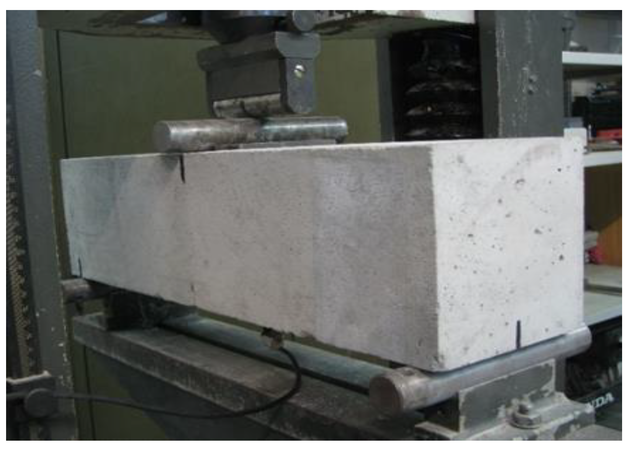
Figure 1 shows one of the 24 prismatic samples in the CMOD test setup.
Before the bending test, the specimens were measured and fitted with a sensor on the lower surface in the notch area. The bending tests were carried out on a HECK-ERT FPZ 100/1 mechanical press, with a set range of 0–20 kN. The samples were loaded until failure. The opening of the crack was measured using a clamp-type track sensor. The test was strain-controlled as follows: a constant loading rate with a strain increment of 0.05 mm/min until a crack opening CMOD of 0.1 mm was used, then the loading rate was increased to 0.2 mm/min, and kept constant until a crack opening CMOD of 4.0 mm.
The crack root opening sensor works on the principle of a resistance strain gauge, which is glued to the outer edge of one of the metal tips. The high precision of the resistive strain gauges allows the measurement of the crack opening with high accuracy, in the order of 0.01 mm. The path between the two tips of the sensor was calibrated with a microscope with a calibrated path scale. A verified calibration relationship between the distance between the semi-rigid tips and the resistance measured on the strain gauge was established and used in the measurement. The steel blades fixing the crack root opening sensor at both ends of the notch in the middle were glued from the bottom face of the test body. The crack opening sensor and load values were continuously synchronously recorded in time at a sampling rate of 10 Hz. The load cycle was carried out in two stages with different deformation rates. After reaching a CMOD of 4.0 mm, the test was terminated.
2.3. Statistics
The measured values were analysed with respect to several hypotheses and procedures. The first step was to obtain statistical parameters such as mean, standard deviation, minimum, and maximum from two sets of 12 tests. This made it possible to determine whether any results were outside the standard variance. The results for both sets of concretes are presented in the next section, where the assessment of the residual strength is also presented as a function of the type of steel fibre.
The next step was to look for a relationship between the input and the measured parameters. The input parameters were chosen to be the exact width and length of the notch. The output parameters were then the load values corresponding to the crack opening of 0.05, 0.5, and 3.5 mm. These two groups were first correlated for both concretes using Pearson’s correlation coefficient (PCC) [
21]. This produced a set of 12 graphical results. The same set was then analysed using linear regression [
22] and the determinant R
2 [
23,
24]. The evaluation of correlation and linear regression indicates whether two parameters have very high, high, moderate, low, or no dependence. For the purpose of this evaluation, a previously published evaluation was applied where the important parameters are the threshold values of 0.3 for low correlation, 0.5 for moderate correlation, and 0.7 for high correlation [
25].
3. Results
The results are logically divided according to the procedure of preparation, testing, and statistical evaluation. As mentioned above, the tests were carried out exactly according to the procedure of EN 14651+A1 [
11] on two sets of 12 samples. The results of the statistical analysis are shown in
Table 3 for concrete with fibre A and
Table 4 for concrete with fibre B.
The tables contain the geometric parameters of the samples, i.e., height, width, notch length, notch width, and distance from the measuring assembly. They also show the results of the force values relative to the respective CMODs from which the residual strength is determined.
A basic evaluation of the minimal and maximal of the set showed that no samples exhibited extreme values outside of the range. Furthermore, the values of the coefficients of variation for the geometric parameters were reasonably low, and the residual strengths did not show significant values either. It is interesting to compare between samples with fibres A and B at the level of coefficient of variation for residual strength, where slightly higher values were observed in the case of fibre B.
3.1. Geometrical Parameters
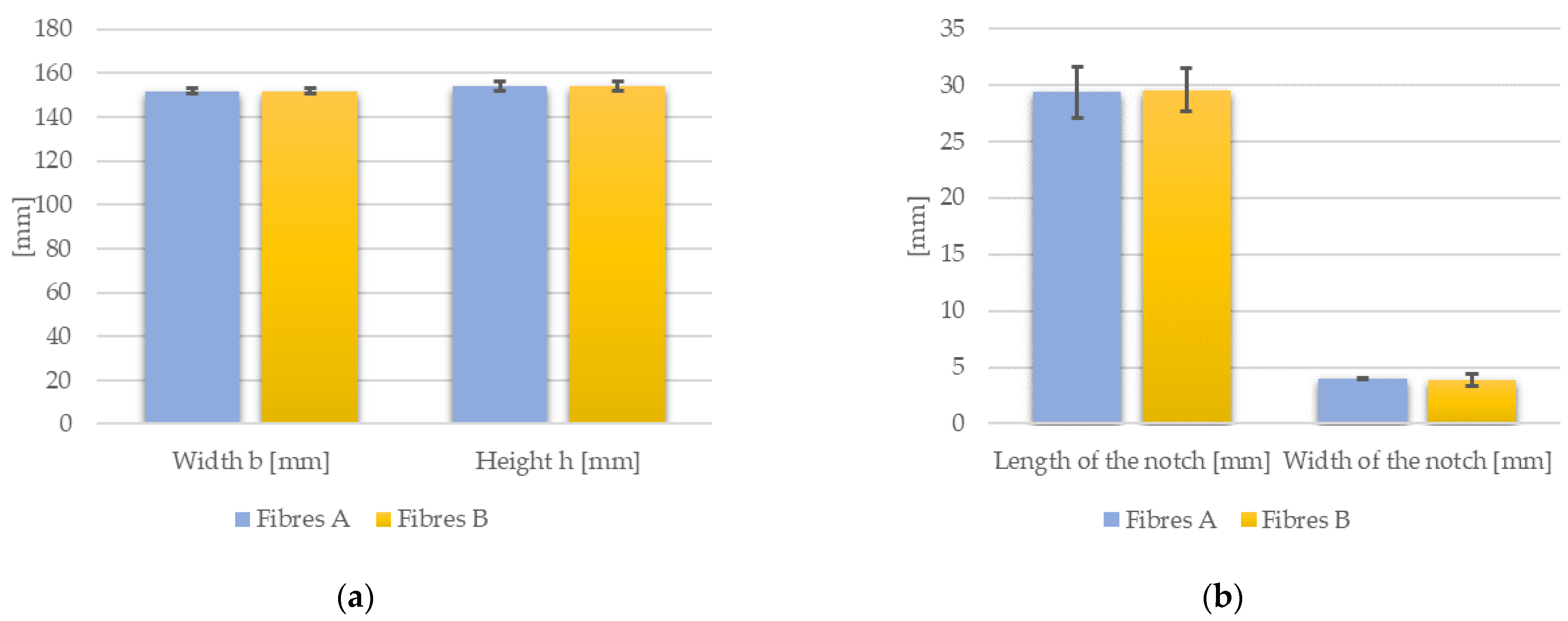
Any evaluation of results comparing two groups of materials for the same test should include a geometry analysis. In this case, a graph of the average cross-sectional dimensions and standard deviations is presented in
Figure 2a. Furthermore, the average length and width of the notch are shown in
Figure 2b. We can see that the deviations for the width and height of the samples were negligible. Similarly, the deviation for the notch width was also similar. However, a larger standard deviation was observed for the length of the notch, but it did not exceed the critical value.
3.2. Tensile Behaviour
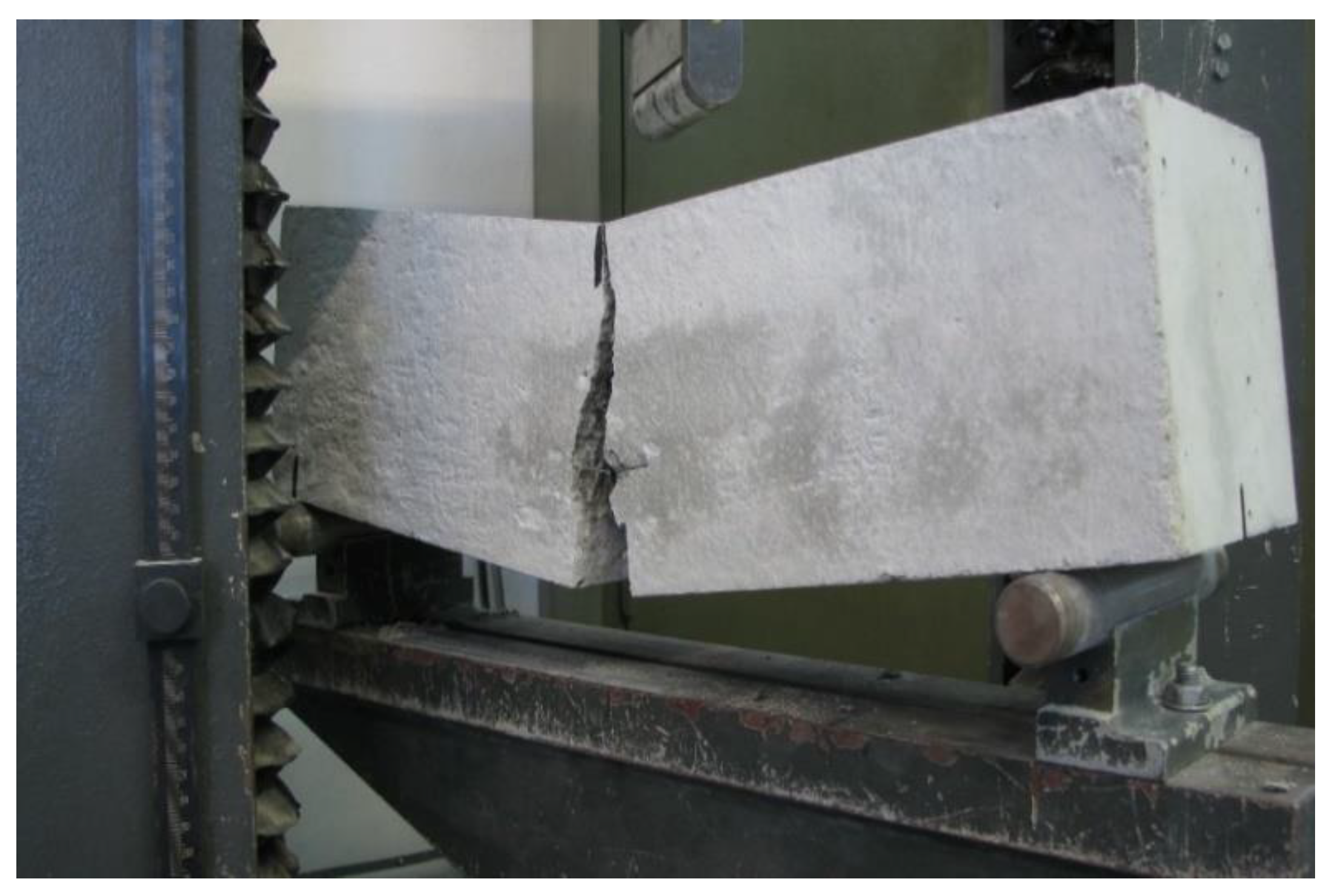
Figure 3 shows the sample after the CMOD test.
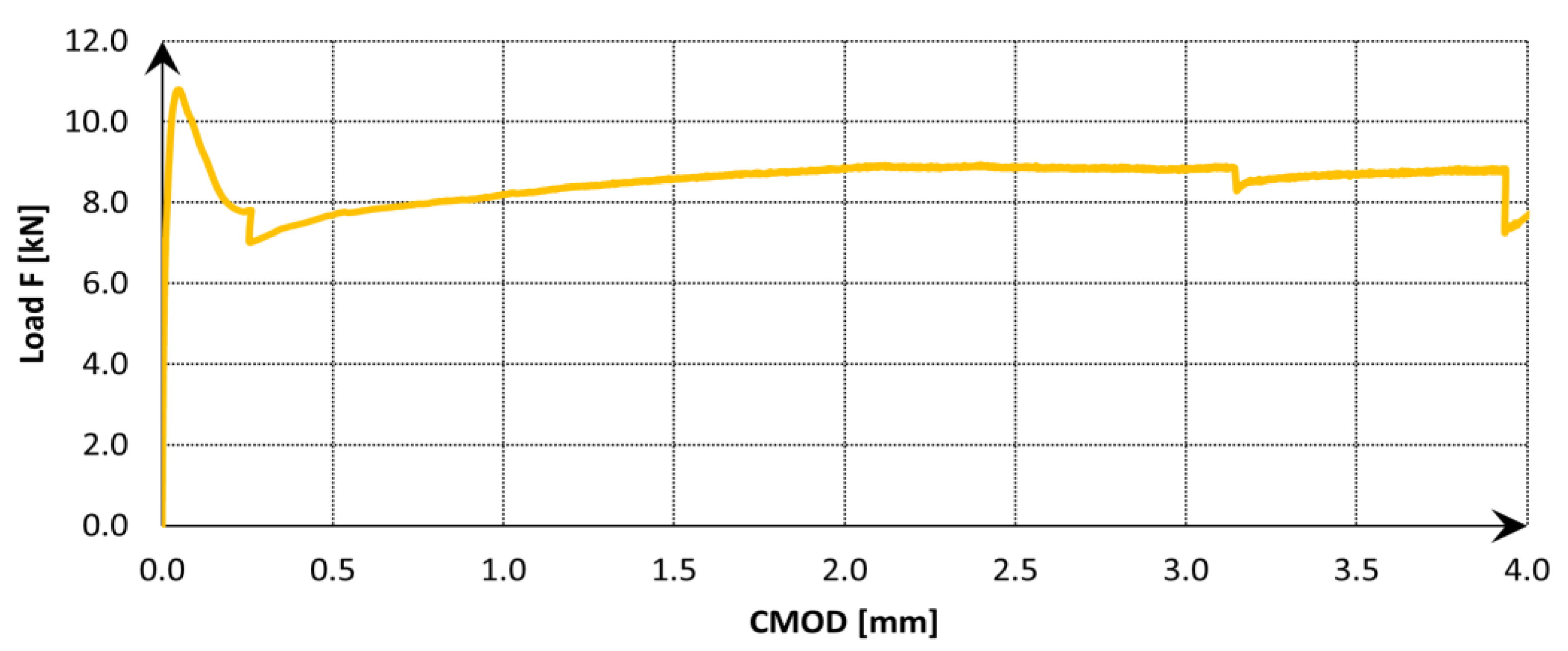
The data acquisition frequency was set the same throughout the test, 5 Hz. During the tests, the load vs. CMOD was always recorded (see example in
Figure 4).
The bending test of a fibre concrete beam with a central notch showed the response of the applied force to the initiation of cracks. As can be seen from the progress of the load test, in the initial phase the concrete behaved in a linear elastic manner, where the tensile stresses at the top of the notch were transferred by the concrete. After the maximum bending force was reached, a micro-crack began to form at the mouth of the notch, which grew into a macro-crack (a crack visible from 0.1 mm) as the strain increased. When the macrocrack formed, the load force decreased and the tensile stress was no longer transmitted by the steel fibres alone, and the concrete no longer acts in tension—the so-called residual strength was formed. As the crack gradually opened, the individual fibres scattered in the concrete structure were activated.
When the strength of the individual fibres was exceeded, the fibres in the lower layers of the cross-section broke (a decrease in strength was visible in the record) and the stress was redistributed again to the other steel fibres higher up the neutral axis of the cross-section [
26].
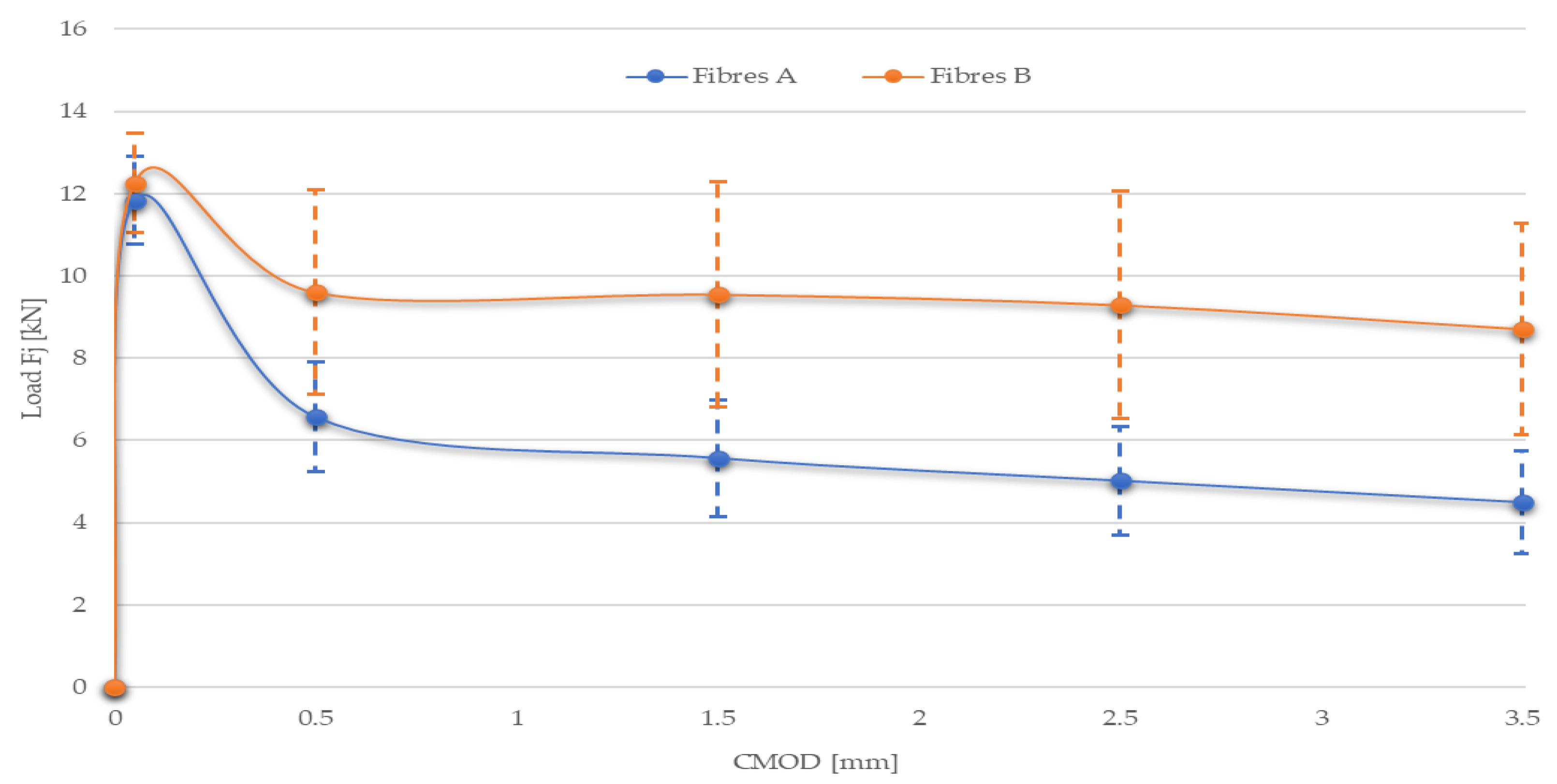
As a next step in the analysis, the average load-CMOD diagram was evaluated for both sets of concretes (see
Figure 5).
This graph shows the values with standard deviations. It can be seen that steel fibre B had a similar value of the load force intercept as fibre A. This is consistent with the prediction that the first response corresponds to the properties of the concrete and its linear-elastic behaviour. In the next section, the differences were larger, by 30% to 50% in favour of the strength of fibres B, which is consistent with the assumptions of better shear properties for longer fibres. Even the limits of standard deviations almost always do not meet them.
The same conclusions can be drawn from
Table 5, which shows the residual capacity calculated for the initial CMOD values. It is evident that steel fibre B always had better values than type A by about 50%.
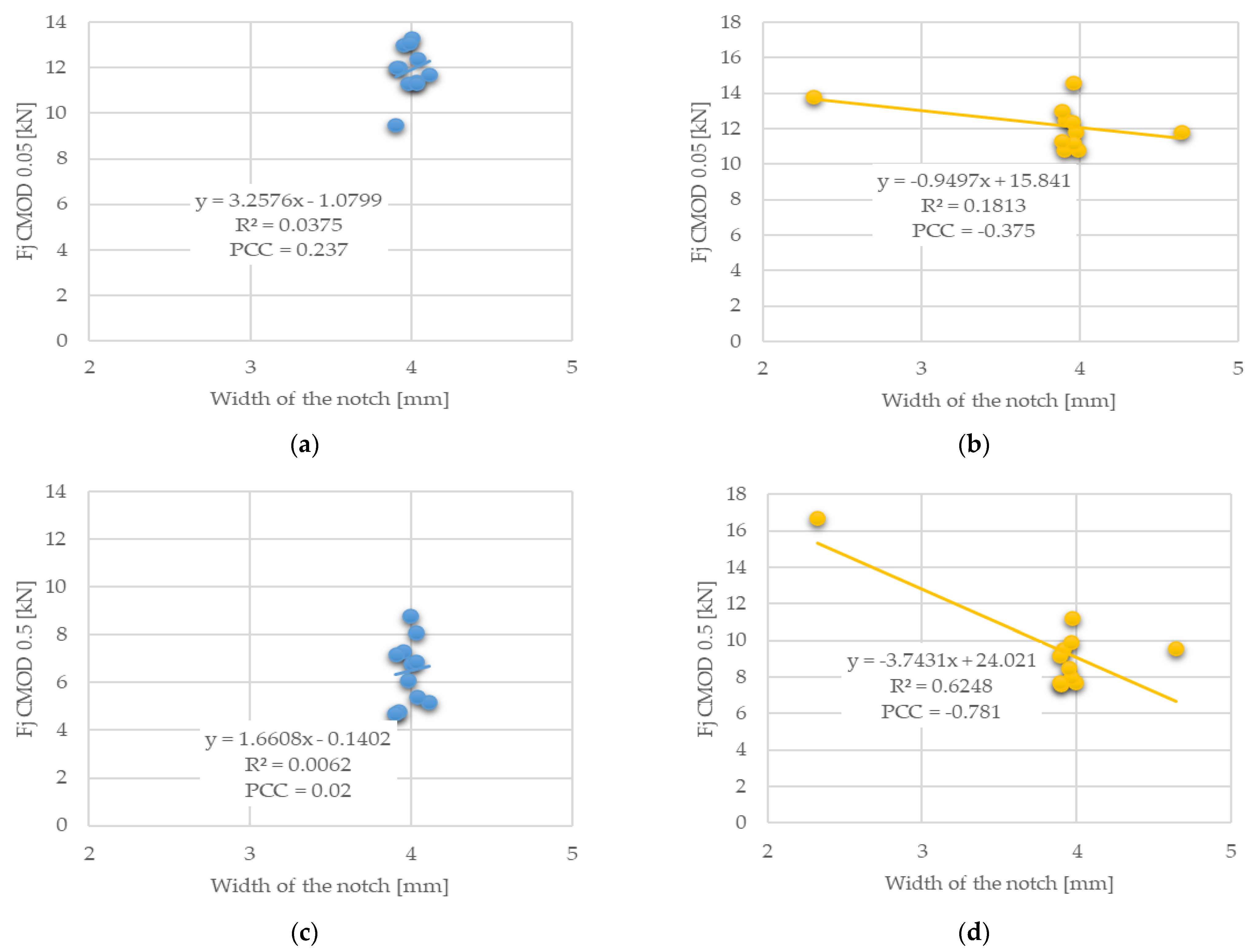
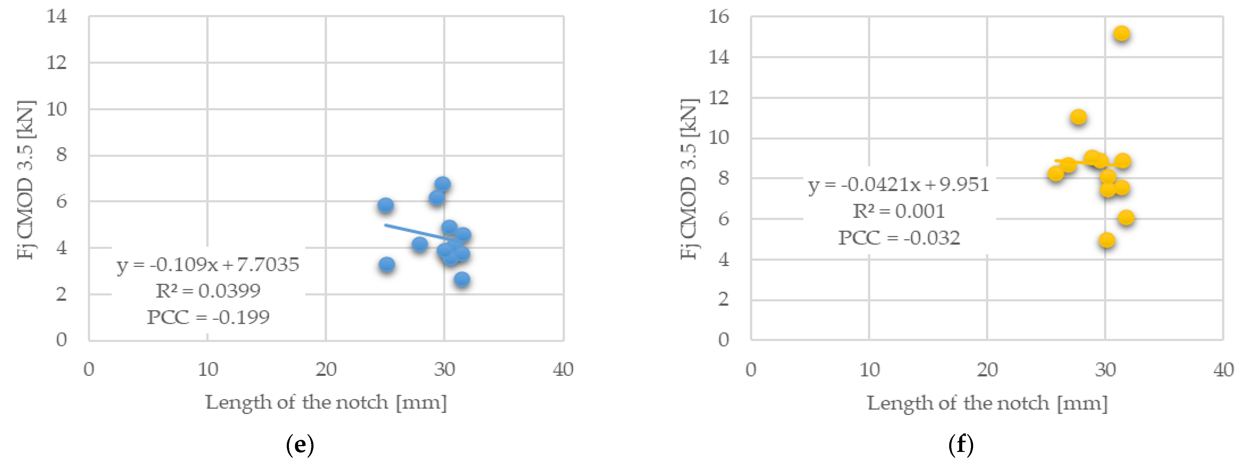
3.3. Correlation of Notch Parameters and Load-CMOD Results
In general, it can be concluded that the residual strength results are significantly dependent on the properties of the fibres and their distribution in the sample. On the other hand, it is worth looking for other influences, and therefore it we proceeded to look for a correlation between the width of the notch and the three strength values associated with CMOD of 0.05, 0.5, and 3.5 mm.
Figure 6 graphically shows the different correlations for the two sets of concretes with fibre types A and B.
Looking at the graphs shown, it can be seen that the force results associated with CMOD 0.05, 0.5, and 3.5 mm were similar. For the fibre A set, little scatter in values was observed, and also very low to no correlation. The set with fibre B had a higher variance, which is due to several outlying values of the width of the notch. This scatter then caused higher values of the correlation factor, even in terms of linear regression.
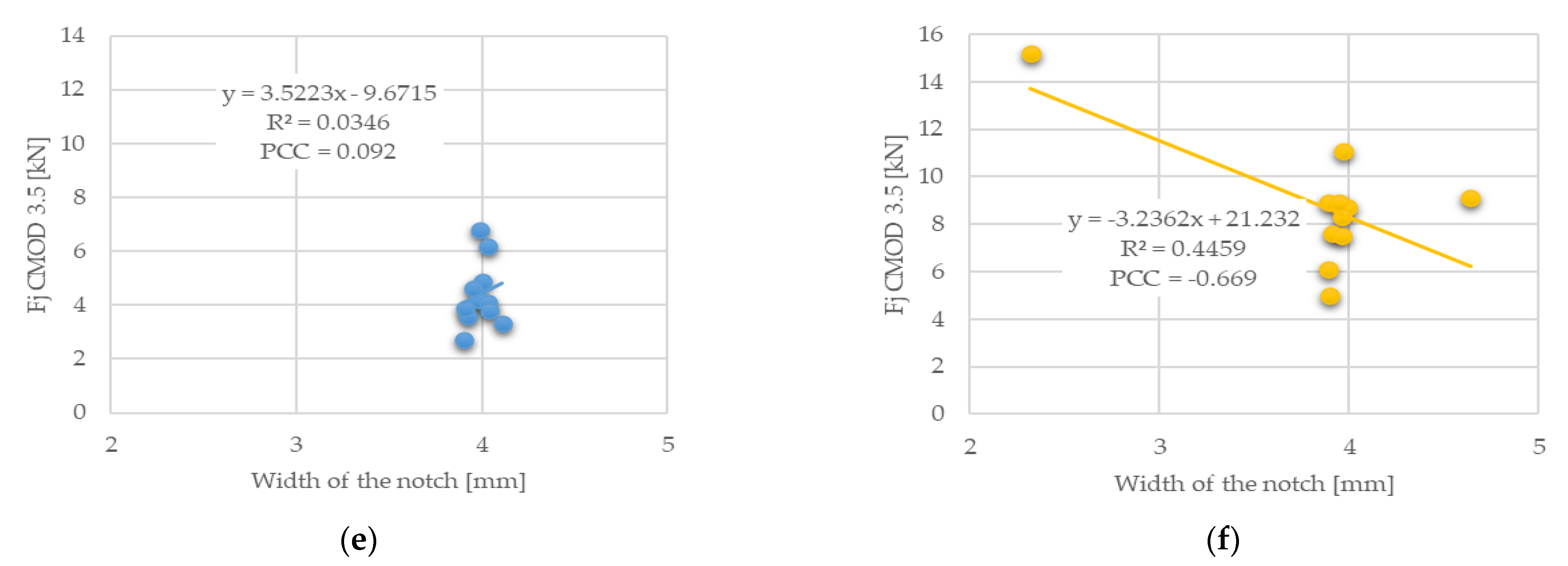
Other correlated parameters were the length of the notch and again the force values adequate for CMOD of 0.05, 0.5, and 3.5 mm, which are shown in
Figure 7.
It can be observed that there were no significant correlation values, and therefore it can be concluded that the length of the notch had no significant effect on the residual strength results. Previous studies [
27] show that the addition of fly ash or slag results in a reduction in fracture energy, which can be attributed to the presence of non-hydrated particles. Since all the concrete samples analysed in this paper were of the same concrete and the difference was only in the type of fibres, it is not necessary to consider this observation.
4. Conclusions
An experimental and numerical study investigating fracture growth was presented in three-point bending tests of notched concrete beams. In this paper, the residual strengths of concrete mix with two types of fibres were verified. It can be said that the smaller the drop in strength after reaching the ultimate capacity in bending, the more effective the fibres are in the cross-section, which is proved by the results. The conclusions can be divided into two parts.
The first part concerns the experiment where the results showed a high variance of values, although the specimens had the same composition with the same amount of fibres. The divergent results are because after the formation of the macrocrack, the tensile strength was transferred to the steel fibres, which were not uniformly dispersed in the beam. This demonstrates general information on the need for improved dispersion and precise placement of fibres.
The second part is related to the evaluation of the fibre type and length. Longer fibres have better values than the other type, which is consistent with the assumption of better shear properties for longer fibres. This is despite the fact that longer fibres have lower tensile strength.
The conclusions presented point to the need and advantages of mathematical evaluation of the results from laboratory tests, especially in the case of the high dispersion found. In such a case, it is desirable to prepare a larger number of tests, and thus expand the database of results. A recommendation is made on the high necessity of mathematical analysis of correlation and regression, which will contribute to a better evaluation of the experiments. Future research will aim to reproduce experimental results using sophisticated numerical models and evaluate their contribution to parametric studies.


