Abstract
In this study, several steel connector shapes were analytically evaluated as potential new seismic energy dissipating devices between vertical precast concrete shear wall panels. Based on the results of analytical and experimental studies, a multiple yield zone (MYZ) connector is proposed due to its improved performance (in energy dissipation) when compared to the conventional U-shaped flexure plate (UFP) device. Unlike the UFP, the MYZ connector provides stiffness and energy dissipation in both horizontal and vertical directions. The response of a shear wall building system utilizing the MYZ or UFP connectors was evaluated using a simplified frame model. The MYZ connector performed better than the UFP alternate both in terms of energy dissipation in the device and with respect to improved structure response. The use of multiple (distributed) yield zones through circular cut-outs is key in the performance enhancement observed with the MYZ connector.
1. Introduction
Shear walls are a common type of lateral load resisting system in precast concrete building construction, especially in high seismic areas. Precast shear walls may consist of several vertical panels placed side-by-side. In such cases, discrete joints are provided along the height between adjacent shear wall panels. One of the commonly used devices for dissipating energy within vertical joints is the U-shaped flexure plate (UFP) or U-bar [1]. This type of connection was first introduced by Kelly et al. [2]. The relative movements of the individual wall segments in an earthquake are intended to cause cyclic yielding of the UFP connector and thus dissipate energy in the device.
There has been increasing interest in seismic resisting systems in which the inelastic behavior is concentrated at localized areas. New and improved energy-dissipating connector devices are needed to meet the ever-increasing seismic design requirements. The key is to design an efficient shape/geometry to maximize energy-dissipation while possessing the required strength to resist the imposed displacements/forces. The design approach used here is to maximize the developed connector force and the achievable connector displacement under that force (to maximize the area under the load-displacement curve, i.e., energy). Ideally, yielding should initiate at relatively small displacements to increase the dissipated (inelastic) energy. Increasing the rigidity of the connector alone would have opposing effects on the developed force and displacement (i.e., increasing force and reducing displacements) and is thus potentially ineffective in increasing the overall energy dissipation. While increasing the force developed in the device could enhance energy dissipation for a given displacement, transfer of excessive forces to the support (concrete shear wall) could potentially cause localized damage in the concrete in the vicinity of the connector. Furthermore, the mode of failure within the energy dissipating device is likely the low-cycle fatigue failure after a limited number of cycles due to relatively large inelastic strains that could be developed.
To address these issues, the overall force-deformation response of such devices, the resistance of concrete in the vicinity of the connector, and the low-cycle fatigue resistance should all be considered. Moreover, such devices should ideally be low-cost, easy to fabricate, easy to install, and easy to replace (when needed following a seismic event). These devices should further serve to improve the seismic structural response of the building through increased energy dissipation.
One of the prominent early works on the seismic design of precast concrete buildings is the Precast Seismic Structural System (PRESSS) research program [3,4]. In the third phase of the PRESSS program, five different precast structural systems were tested [5]. A six-story precast shear wall building was tested with connectors between shear wall panels [1].
The UFP connector (which is now commonly used in precast shear wall buildings) was used in the PRESSS program [5]. This type of connector can develop a vertical shear force in the connector through a rolling bending action caused by relative movement between the adjacent wall panels. UFP offers very little resistance to relative horizontal movement, which makes it especially suitable for locations where control joints are required. Force-displacement test results have shown steady hysteretic response resulting from the rolling and bending action that result in localized yielding [1].
Several connectors were tested under the PRESSS program [1]. The UFP device was the recommended connector in that study. The UFP reportedly exhibited twice as much energy dissipation as the second and third best connectors in that study. Lu et al. [6] proposed using built-in vertical slits in the shear wall to control stiffness. They further added various energy dissipating devices within the slits. More recently, Dang et al. [7] proposed X-shaped metal dampers with enhanced energy dissipating capability for use at locations along vertical joints between adjacent precast wall panels. Zhu et al. [8] proposed a new energy dissipating connection system between precast concrete shear wall panels that included replaceable bolted low-yielding plates.
Dal Lago et al. [9] proposed energy dissipative connection systems (friction-based or plasticity-based) between building cladding panels and precast frames. De Stefani and Scotta [10] studied the efficiency of using elasto-plastic connections between precast concrete buildings and cladding panels. Basereh et al. [11] proposed a concept involving weakening (partial cuts in concrete walls) and self-centering using post-tensioning retrofit seismically deficient concrete shear walls.
2. Objectives and Scope
The primary objective of this research was to develop a new type of energy-dissipating steel connector for use at vertical joints between adjacent precast shear wall panels (or other similar applications) to achieve significant energy dissipation through changes in the shape and geometry of the device. The new device had to: (1) fit within the overall physical dimensions of the UFP connectors; (2) adequately transfer forces to the reinforced concrete walls without major damage in the vicinity of the connection; and (3) substantially improve energy-dissipation properties when compared to UFP. The new device would ideally be easy to fabricate and install in the field.
An analytical and experimental program was conducted to meet the above objectives. The analytical program first included a limited number of topology optimization models for a broad idea of optimized shapes. This was followed by more detailed non-linear finite element analyses of different connector geometries to maximize energy dissipation, reduce displacement at first yield, reduce maximum inelastic strain (to enhance low-cycle fatigue resistance), and limit the total force to a level that can be resisted by the adjoining reinforced concrete elements. The initial topology optimization models were run within both the ABAQUS and ANSYS finite element programs. However, the topology optimized shapes were not the final shape considered. This is due to the fact that other limiting considerations described above made a broad topology optimization design not practical. Although the idea of the final shape was not based on the topology optimization results, the limited topology optimization analyses were informative in the process of progressive (trial and error) analyses using the nonlinear finite element models performed within ANSYS. An initial device was selected based on these analyses and ½-scale experiments were performed to assess the concept. Although the results were promising, a relatively early low-cycle fatigue failure was noted. Therefore, additional analyses were performed, a revised shape was conceived, and scaled model tests were performed on the new device to arrive at a proposed solution. Finally, a simplified finite element model of a scaled shear wall building subjected to seismic loading was generated. This building model was adopted from an earlier PRESSS study [5]. The building frame model was analyzed using the new proposed connector as well as the UFP device. The connectors were modeled as non-linear spring elements with properties determined from scaled physical tests of the connectors. A performance comparison was then made between the shear wall building models incorporating the different devices.
2.1. UFP Connector
Figure 1 shows a sketch of the UFP connector as presented in the PRESSS report [1]. The Figure shows a two-third scale model of a full-size UFP connector that was tested in the PRESSS program [1]. A 3-dimensional Ansys model with solid elements (Solid 186) was used to model the 2/3-scale model of the UFP device to allow comparisons with the experimental results. Figure 2 shows the finite element mesh and boundary conditions. A fixed boundary condition was modeled at face “A” and a uniform vertical displacement was imposed at face “B” (Figure 2b). No other restraints were imposed at face “B”. The UFP steel material (304 stainless steel) was modelled as elastoplastic with a yield strength of 31.2 ksi (215 MPa). Seventy displacement cycles of increasing amplitudes were simulated up to a displacement of 1.6 in (41.6 mm).
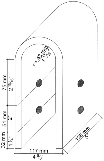
Figure 1.
UFP details and dimensions of two-third scaled model as presented by the PRESSS program.
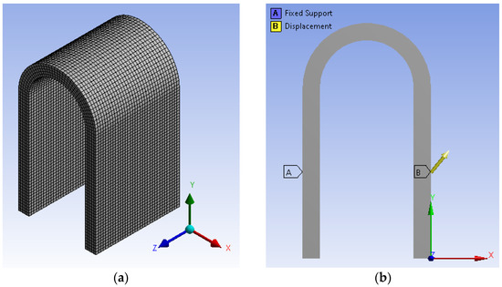
Figure 2.
Finite elements model in ANSYS workbench: (a) meshed shape; (b) boundary condition.
Figure 3 shows a comparison of the FEM and PRESSS experimental results. The maximum reaction force in the model was on the order of 28 kips (97.86 kN), which was higher than the experimental results 25.0 kips (111 kN) reported in the PRESSS report [1]. The force versus displacement curves for the computer model were similar to the PRESSS results [1].
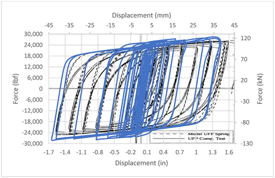
Figure 3.
Finite element force-displacement response of 2/3-scale UFP connector: comparison of UFP experimental (solid blue line) and FEM (dashed black line) responses.
2.2. Development of the New Seismic Connector
Topology optimization modeling was initially used to develop early concepts for connector shapes. A solid steel block was modelled with the external geometry and boundary conditions as described for the UFP connector. The shape was then optimized using the ABAQUS topology optimization tools. Cyclic vertical displacement was applied on one side face. The limited objective for this topology optimization was to maximize the strain energy while setting a maximum volume constraint. This optimization model could not include, due to software limitations, other limiting conditions such as maximum force and inelastic strain limits. Figure 4 shows the initial model configuration and boundary conditions (Figure 4a) as well as the resulting optimized shape and stress contours (Figure 4b). The optimized shapes were then analyzed using nonlinear FEM in ANSYS. Based on these analyses, it became clear that localized high inelastic strains areas would develop at a limited number of small zones in the topology optimized shape. When increasing the thickness of the rib, the reaction forces would increase substantially. Thus, the concept of iterative nonlinear finite element analyses (trial and error approach) was adopted, in lieu of topology optimization, to meet the overall goals of this study.
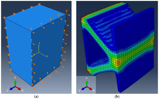
Figure 4.
Optimized shapes: (a) general initial shape and boundary condition of ABAQUS model; (b) optimized shape after running the analysis.
During the preliminary FEM analyses, several different geometries were investigated, and their shapes were analyzed using ABAQUS models to assess their response with respect to the study objectives. Details of these analyses are reported in a dissertation by Aljuboori (2019). One of the primary reasons that many of the early shapes were not selected for further investigation was the development of relatively high reaction force, which would be exerted on the supporting shear wall members. Although higher reaction force would result in higher energy dissipation (for a given connector displacement), the force must be limited to avoid significant damage to concrete, and thus most of the early shapes were not selected.
Several geometries were modeled (and progressively modified) to obtain a shape that could conform with the stated criteria for this study. An important issue was the control of large and highly localized inelastic strains that could lead to early low-cycle fatigue failure. The approach chosen was to develop multiple inelastic strain zones instead of one or two highly localized inelastic strain zones. If low-cycle fatigue failure is initiated at one of these multiple zones, the result would not be a sudden and complete failure. The strategy used was to employ a combination of circular shapes to achieve multiple yield zones. Circular openings have the advantage of reduced stress (strain) concentration (compared to sharp corners) and can be manufactured relatively easily through drilling.
Based on an observed early low-cycle fatigue failure in an initial scaled test [12], it was decided that increasing the number of circular openings within the shape could assist with reducing the localized high plastic strains and improving the chance of the connector functioning (at reduced capacity) even with an initial low-cycle fatigue crack. The set of shapes examined consisted of a single plate with a thickness of 1 in (25.4 mm) and several larger and smaller cut-out circles. Geometric symmetry was maintained about the vertical and horizontal axes. Figure 5 shows the evolution of the last set of new shape designs that were examined (designated NS1 through NS4). Each shape was analyzed and examined for the reaction force developed and inelastic strain peaks in hot spots under cyclic displacements.
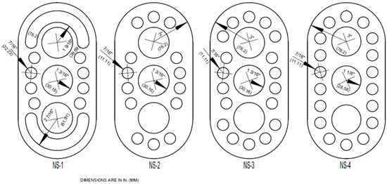
Figure 5.
Shapes NS1 thru NS4.
Figure 6 shows the final selected shape (NS5) including the full-size dimensions of the plate. The NS5 connector is designated as multiple yield zone (MYZ) connector in subsequent discussions. In field applications, one plate would be welded to each side of the shear wall (i.e., two identical ½ in or 12.7 mm plates at each connection). The vertical line on either side of the plate (in Figure 6) would be welded to flat steel plates that would be embedded in the concrete shear walls. It should be noted that the weld lines are straight, except for a small area at each end where the weld is extended into the curved zone for a short distance of 1 1/8 in (28.5 mm) as shown in Figure 6. The finite element analyses indicated that extending the weld area to include some of the upper and lower curved edges would improve the inelastic strain response.
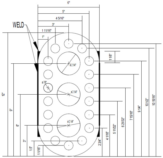
Figure 6.
Sketch of Shape MYZ (total plate thickness of 1 in or 25.4 mm representing two identical ½ in or 12.7 mm plates).
In the nonlinear FEM analyses of the MYZ plate (in ABAQUS), the 3-D solid element (C3D8R) was used to model the steel plate. A mesh size of 1/8 in (3.2 mm) was used, which resulted in a total of 15,701 elements as shown in Figure 7a. A mild, low carbon non-linear elastoplastic steel material model (representing ASTM A36 steel) with a yield strength of 36 ksi (250 MPa) was used. Figure 7b shows the boundary conditions for the MYZ plate representing welded attachments. One side was fixed along the weld lines, while the opposite side was subjected to a uniform displacement along the weld line. The imposed displacement amplitudes were adopted from the PRESSS program and adjusted for a full-scale model (shown in Figure 8).
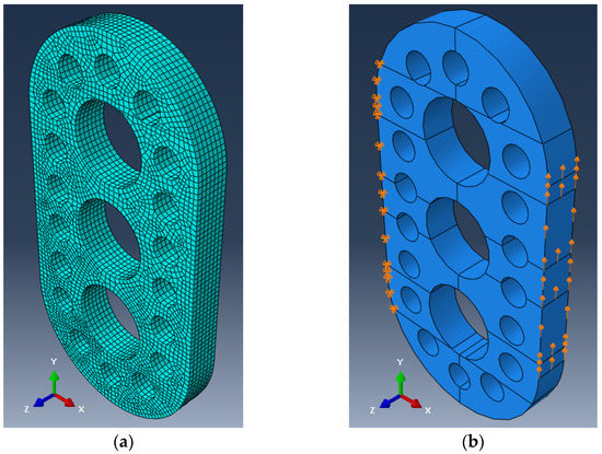
Figure 7.
FEM model of the MYZ device: (a) mesh; (b) boundary conditions.
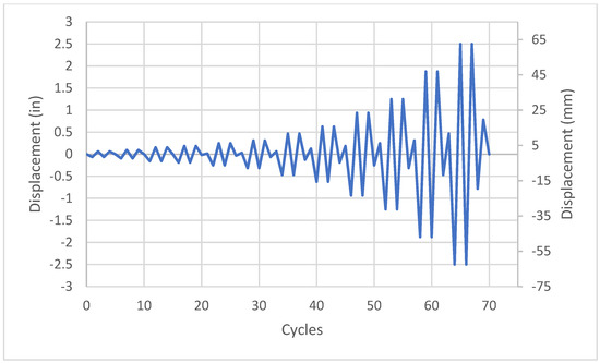
Figure 8.
PRESSS displacement cycles for full-size connector tests.
Contour maps showing maximum principal plastic strains for the ±2.5 in (64 mm) displacement cycles are shown in Figure 9. As expected, the plastic strains were primarily concentrated in multiple bands between circular openings. Figure 10 shows the force versus vertical displacement graph. This graph shows yielding at relatively small displacements and the response exhibits high energy-dissipating hysteretic behavior. The maximum reaction force was approximately 100 kips (445 kN) for a 1 in (25 mm) total plate thickness. In the field, it is expected that two ½ in (12.7 mm) plates would be used, one on either face of the shear walls. Therefore, the maximum transferred force to each side of the shear wall would be on the order of 50 kips (223 kN).
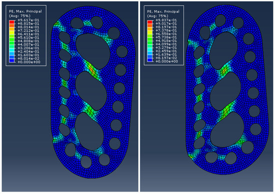
Figure 9.
Maximum principal plastic strains for upward 2.5 in (64 mm) displacement (right) and downward 2.5 in (64 mm) displacement (left) for the MYZ shape.
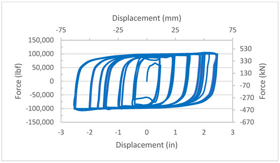
Figure 10.
FEM results—vertical force vs vertical displacement for MYZ connector.
Although the relative movements between the two adjacent precast panels have been generally assumed to be in the vertical direction (as in UFP connectors), some relative horizontal movement is also expected. Due to its shape, the conventional UFP connector offers very little resistance to relative horizontal displacements. However, the MYZ shape is expected to offer much higher resistance in the horizontal direction. Therefore, the MYZ model was also analyzed under a relative horizontal displacement. One side of the model was fixed while the opposite side was displaced (uniformly) based on the displacement cycles shown in Figure 8.
The horizontal force-displacement response of the MYZ connector is shown in Figure 11. The stiffness and strength of the MYZ connector in the horizontal direction is significantly higher than the horizontal UFP response. These results (as well as experimental results) are used to develop bilinear spring models (for both vertical and horizontal movement) for inclusion in the shear wall building model (discussed later).
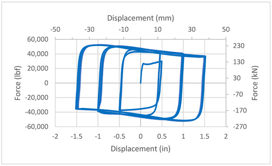
Figure 11.
FEM results—horizontal force vs horizontal displacement for MYZ connector.
3. Localized Resistance in Concrete Shear Wall
An analysis of the effect of the reaction force on the supporting shear wall is needed to make sure that the wall would not fail locally due to excessive forces from the connector. There are a wide variety of anchorage and reinforcement details that could be used in the concrete in the vicinity of the connection. An example connection detail was evaluated using nonlinear finite element modeling to assess the general effects. A description of this work is given by Aljuboori [12] and a summary follows.
First, a model of the entire wall was generated in ANSYS. The purpose of this first wall model was to determine the zone of influence of reaction force developed at the connector so that a smaller model of a portion of the wall could be developed for detailed examination [12]. An anchorage plate with four ½ in (12.7 mm) diameter anchor bars was modelled. The reinforcing steel in the wall consisted of No. 6 (19 mm) bars at 6 in (152 mm) spacing in the vertical direction and No. 4 (12.7 mm) bars at 12 in (25 mm) spacing in the horizontal direction. The Concrete Damage Plasticity (CDP) model within ABAQUS was used. Elastoplastic steel material was used for the steel reinforcement, the connector, and the embedded anchorage bars. Results indicated that additional localized reinforcement would be needed to resist the 100 kip (445 kN) peak force that could be imposed by the connector (two ½ in or 12.7 mm plates). The anchorage design can be performed using existing seismic anchorage design procedures based on applicable design codes.
4. Scaled Model Testing of MYZ Device
Six half-scale specimens of the MYZ device were fabricated and tested. The test setup was designed to test two specimens at a time, to minimize specimen bending and to apply pure shear forces on each specimen. Therefore, three sets of tests were formed. Figure 12 shows the setup for testing in a universal test machine. All dimensions were half the corresponding full-size dimensions. As discussed earlier, it is expected that two ½ in connector plates would be used in the field (one on each face of the shear wall). The two scaled connector plates were simultaneously tested. This arrangement allows the scaling rules to be applied based on a dimensional scale factor of one-half. The steel that was used in the fabrication of the specimens and test setup was A36 steel. A universal servo-hydraulic test machine with a capacity of 110 kips (489 kN) was used for the tests. The imposed (scaled) displacement cycles used in the tests were based on the protocol used by the PRESSS program [1,13,14]. The protocol of full-size specimen is shown in Figure 8. A ½ scale version of that protocol was used for this testing [12].
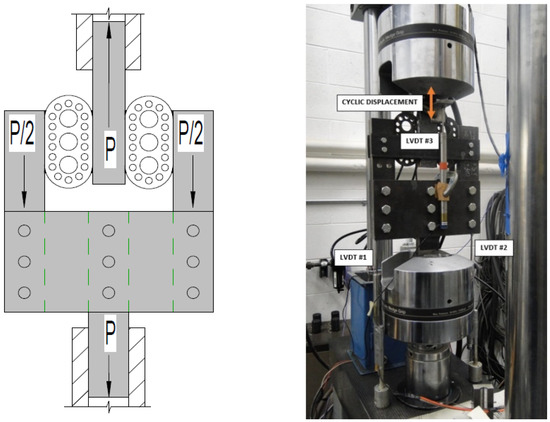
Figure 12.
MYZ test setup between the jaws of the universal test machine.
Only one set of results (MYZ-1) are discussed in detail in this paper. All tests are described in detail by Aljuboori (2019). In the MYZ test, the specimen on the left developed a crack initiating at the top right corner of the specimen as shown in Figure 13 at a scaled displacement of 0.313 in (7.95 mm) after sustaining 30 displacement cycles. However, the test continued until a maximum displacement of 0.51 in (13.0 mm) at which time the specimen failed (after sustaining a total of 35 displacement cycles). It should be noted that these scaled displacements should be multiplied by 2 to obtain the corresponding displacement on full size devices (in this case a maximum displacement of 1.02 in or 26 mm). Also, based on scaling laws, the force in the full-size device would be four times the force in the model tests (square of the dimensional scale factor of 2). Two additional MYZ specimens were tested [12]. Results were consistent with the first specimen with similarities in failure mode as well as the maximum load and displacement achieved [1].
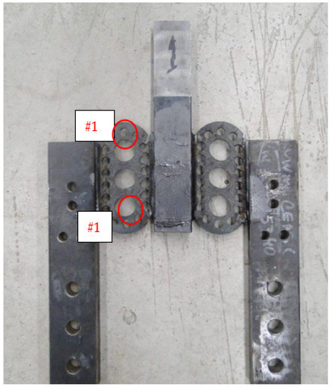
Figure 13.
Failure mode of MYZ-1.
The specimens exhibited a reasonably steady hysteretic behavior with high energy dissipation. The failure mode of the specimens was due to low-cycle fatigue. Figure 14 shows a comparison between the scaled-up experiment (full-scale equivalent) and FEM model results. The initial low-cycle fatigue crack reduced the peak force, but resistance continued until an overall failure occurred at a displacement of 1.02 in (26 mm). The reduced force generated in the cracked state (about 45 kips) was still nearly double the maximum force generated with the UFP device.
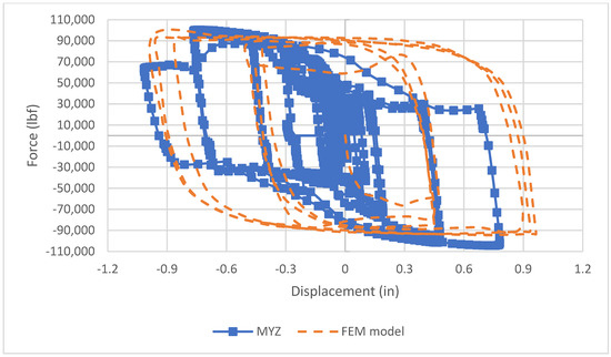
Figure 14.
Load-displacement results—scaled-up experimental results vs FEM for MYZ-1 Specimen.
4.1. FEM Model of Shear Wall Building
A simplified FEM model of a shear wall building was needed to confirm and compare the responses of the new MYZ device with the conventional UFP connector. Sritharan et al. [14] developed a simplified frame model to represent a 60% scaled shear wall building model used in the PRESSS program (Figure 15). In this study, the ANSYS finite element software was used to recreate the same 60% scale building model with the same member properties. Lumped masses were added at the nodes (labeled A through J) as shown in Figure 15b. In addition to the two wall panels, the gravity columns in the building were also modeled as shown in Figure 15. The base springs (compression only) were defined as a “Body to Ground” type of spring with properties taken from Sritharan et al. [14]. ANSYS spring elements for the PT tendons were also based on the properties used by Sritharan et al. [14]. The model was subjected to base excitation with a ground acceleration history shown in Figure 16.
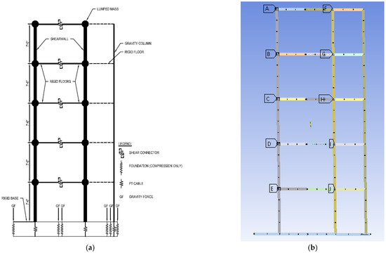
Figure 15.
ANSYS building model: (a) concept model, (b) Ansys presentation (lumped masses are designated A through J).
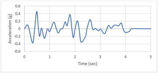
Figure 16.
Ground Acceleration (Adapted from Ref. [14]).
Element type COMBIN39 was used to model the bi-linear springs representing the connector devices. This type of element allows inputting the load-displacement response and can account for energy dissipation during loading and unloading. The base boundary conditions were set such that the vertical and out-of-plane horizontal movements were restrained, while in-plane horizontal movements were unrestrained. The scaled force versus displacement data for the UFP and MYZ springs were obtained from the PRESSS program, and the tests reported here, respectively. Figure 17 and Figure 18 show the scaled (for the 60% scale building) bilinear vertical load versus displacement response for the UFP and MYZ spring models, respectively.
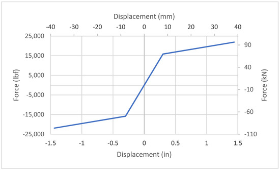
Figure 17.
Bilinear load-displacement response for vertical movement in UFP connector—scaled for a 60% building size.
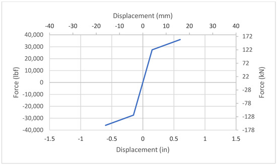
Figure 18.
Bilinear load-displacement response for vertical movement in MYZ connector—scaled for a 60% building size.
Figure 19 shows the force vs displacement relationship for the UFP and MYZ springs at the connector located at the top of the shear wall (highest expected displacement). The maximum displacement for this UFP connector was on the order of ±1.4 in. (35.6 mm) and the maximum force was approximately 21,500 lbf (95.6 kN). For the MYZ connector, the maximum displacement was approximately 1.2 in (30.5 mm) and the maximum force was on the order of 46,700 lbf (207.7 kN). The UFP connector had higher displacement and lower reaction force (connector force) than the MYZ connector. More importantly, the MYZ connector dissipated significantly higher energy (area under the load-displacement curve) than the UFP connector.
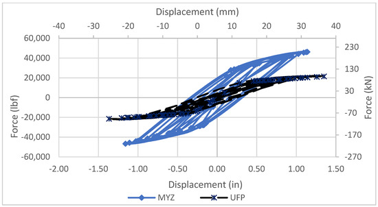
Figure 19.
Connector force vs displacement in the UFP and MYZ connectors.
Two other models were also run in which the connectors were either rigid links (“rigid model”) or no connectors were used (“free model”). These two limiting models were intended to bracket the response to assess the relative influence of the connectors. Figure 20 shows the story and overall drifts of the building model with UFP, MYZ, rigid and free connectors. The maximum drift at the top of the scaled building was 4.32 in (109.7 mm) and 3.68 in (93.5 mm) for the UFP and MYZ connectors, respectively. Maximum drifts for the rigid and free models were 0.86 in (21.8 mm) and 4.81 in (122.2 mm), respectively. As expected, the rigid model had the lowest drift, and the free model had the highest drift. The building with rigid connection at discrete points acts as a single unit with no energy dissipation at the connections. The MYZ connector exhibited lower drift compared to the UFP connector. The higher stiffness and strength of the MYZ connector is an important contributing factor.
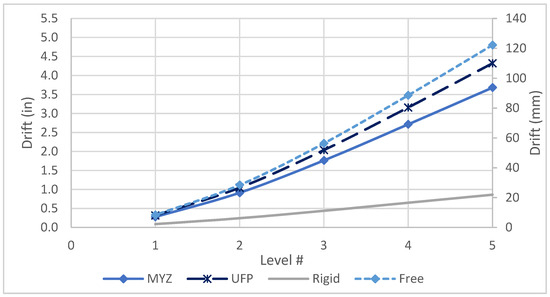
Figure 20.
Building and floor drifts for all models.
Figure 21 exhibits the base shear for the scaled building models with UFP and MYZ connectors. The maximum total base shear for building with UFP and MYZ connectors were 1834 kips (8158 kN) and 2175 kips (9675 kN), respectively. The higher stiffness of the MYZ device increased the total base shear when compared with the UFP connector. The base shears for the rigid and free connectors were 2.7 × 10⁵ kips (1.2 × 10⁶ kN) and 1085 kips (4.83 kN), respectively. The significantly higher base shear for the rigid model would mask other curves and it is therefore not shown in Figure 21. The building model with the MYZ connector developed slightly higher base shear when compared with the UFP model.
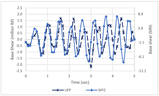
Figure 21.
Base shear for UFP and MYZ.
Figure 22 shows the accumulated dissipated energy for the top connector in various models. The total dissipated energy levels for the top UFP and MYZ connectors were 1,097,605 lbf·in (124.0 kN·m) and 2,157,428 lbf·in (243.8 kN·m), respectively. The model with the MYZ connector dissipated nearly twice as much energy as the UFP model.
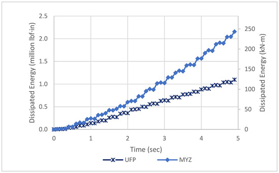
Figure 22.
Cumulative dissipated energy for UFP and MYZ.
4.2. Analysis with Vertical and Horizontal Springs
The UFP connector has relatively small stiffness and strength in the transverse direction (horizontal direction in a building) while the MYZ connector can provide relatively high stiffness and energy dissipation in both directions. To illustrate the effect, two building models were generated, each incorporating both vertical and horizontal springs, for the UFP and MYZ connectors. These new models were similar to the models described previously except for the fact that horizontal springs were added based on the data obtained from the FEM horizontal response analyses. Figure 23 shows the vertical force and displacement in the top UFP and MYZ connectors when dual springs (vertical and horizontal) are modelled. The vertical displacement is reduced significantly compared to when a vertical spring alone was used (Figure 23).
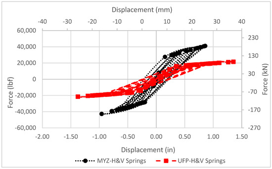
Figure 23.
Vertical force vs vertical displacement responses for single UFP and MYZ connectors located in the building model with horizontal and vertical springs.
Figure 24 shows the building and story drifts for all models. It could be seen that the free and rigid models bracketed the responses from the MYZ and UFP connector models. The performance of the MYZ model (with horizontal and vertical springs) was significantly better with a total drift of 3.32 in (84.3 mm) compared with 4.54 in (115.3 mm) for the model with UFP connector (as shown in Figure 24). Base shear forces for all models are shown in Figure 25. There was only a slight difference in base shear with the UFP model exhibiting lower base shear. Finally, Figure 26 shows that the cumulative energy dissipation obtained from the model with the MYZ connector was significantly higher (70% higher) than the corresponding model with UFP connectors. It is believed that the MYZ reached yield early and developed higher force resulting in higher energy dissipation.
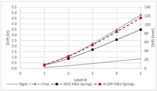
Figure 24.
Story drift for all models (incorporating horizontal and vertical springs).
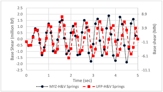
Figure 25.
Base shear for MYZ and UFP connectors in building models with horizontal and vertical springs.
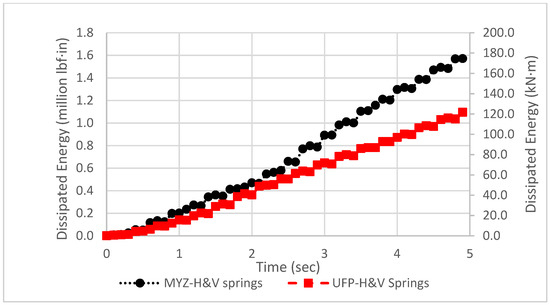
Figure 26.
Cumulative dissipated energy for building models with UFP and MYZ connectors.
5. Summary and Conclusions
A new type of energy-dissipating steel connector (MYZ) is developed for use at vertical joints between adjacent precast concrete shear wall panels. The MYZ connector consists of two plates with circular cut-outs that are welded to anchorage plates embedded in both faces of the adjacent vertical shear walls. For a given displacement, the MYZ device can significantly enhance energy dissipation when compared with the conventional UFP connector. Unlike the conventional UFP connector, the MYZ connector provides significant stiffness in both the horizontal and vertical directions. Additional steel reinforcing bars may be required to resist the higher forces exerted on the shear walls by the MYZ connector.
A simplified 60%-scale frame model of a 4-story shear wall building [14] was used to assess the relative performance of the UFP and MYZ connectors. Results show that the shear wall modeled with MYZ connector dissipated higher energy and exhibited lower drift under a simulated ground motion (when compared with the same building model incorporating the UFP device). The fabrication process for the new MYZ connector is expected to be relatively easy since it incorporates circular cut-outs in a plate, which can be easily produced in typical steel fabrication shops.
Author Contributions
Conceptualization, H.T.; data curation, M.A.; formal analysis, M.A.; investigation, M.A.; methodology, H.T.; project administration, H.T.; supervision, H.T.; validation, H.T. All authors have read and agreed to the published version of the manuscript.
Funding
This research was conducted through internal funding by the Department of Civil and Environmental Engineering at the University of Wisconsin Milwaukee.
Institutional Review Board Statement
Not applicable.
Informed Consent Statement
Not applicable.
Data Availability Statement
The data used to support the findings of this study are available from the corresponding author upon request.
Acknowledgments
The authors appreciate the support of the University of Wisconsin—Milwaukee. The authors also thank Rahim Reshadi for his help with preparation of specimens and testing.
Conflicts of Interest
The authors declare no conflict of interest.
References
- Aljuboori, M. An Energy Dissipating Seismic Connector for Precast Concrete Shear Walls. Ph.D. Thesis, Department of Civil and Environmental Engineering, University of Wisconsin—Milwaukee, Milwaukee, WI, USA, August 2019. [Google Scholar]
- Basereh, S.; Okumus, P.; Aaleti, S. Reinforced Concrete Shear Walls Retrofitted Using Weakening and Self-Centering: Numerical Modeling. ASCE J. Struct. Eng. 2020, 146, 04020122. [Google Scholar] [CrossRef]
- Conley, J.; Sritharan, S.; Priestley, M.J.N. Precast Seismic Structural Systems PRESSS-3: The Five-Story Precast Building Vol.3-5: Wall Direction Response. Depratment of Structural Engineering, University of California, La Jolla, California. Available online: https://www.pci.org/PCI_Docs/Design_Resources/Guides_and_manuals/references/PRESSS/PRESSS-Phase-3_The-Five-Story-Precast-Test-Building_Vol-3-5_Wall-Direction-Response.pdf (accessed on 1 May 2019).
- Dal Lago, B.; Biondini, F.; Toniolo, G. Seismic performance of precast concrete structures with energy dissipating cladding panel connection systems. Struct. Concr. 2018, 19, 1908–1926. [Google Scholar] [CrossRef]
- Dang, L.; Liang, S.; Zhu, X.; Zhang, M.; Song, Y. Seismic performance of precast concrete wall with vertical energy-dissipating connection. Struct. Des. Tall Spec. Build. 2020, 30, e1820. [Google Scholar] [CrossRef]
- De Stefani, L.; Scotta, R. Seismic Behavior of Precast Buildings with Dissipative Connections. Front. Built Environ. 2021, 7. [Google Scholar] [CrossRef]
- Kelly, J.M.; Skinner, R.I.; Heine, A.J. Mechanism of Energy Absorption in Special Devices for use in Earthquake Resistant Structures. Bull. N. Z. Soc. Earthq. Eng. 1972, 5, 63–88. Available online: https://www.nzsee.org.nz/db/Bulletin/Archive/05(3)0063.pdf (accessed on 1 May 2019). [CrossRef]
- Krawinkler, H. Loading Histories for Cyclic Tests in Support of Performance Assessment; Deptartment of Civil and Environmental Engineering, Stanford University: Stanford, CA, USA, 2009; Available online: https://pdfs.semanticscholar.org/746d/a78be1d328c49ee7683143a6a0bb1d4380d5.pdf (accessed on 1 May 2019).
- Lu, X.L.; Wu, X.H.; Meng, L. Seismic behavior of a new type of seismic energy dissipation shear wall system. Struct. Eng. Mech. 1997, 5, 167–175. [Google Scholar] [CrossRef]
- Priestley, M.J.N. Overview of PRESSS Research Program. PCI J. 1991, 36, 50–57. Available online: https://www.pci.org/PCI/Publications/PCI_Journal/Issues/1991/July-August/Overview_of_PRESSS_Research_Program.aspx?WebsiteKey=5a7b2064-98c2-4c8e-9b4b-18c80973da1e (accessed on 1 May 2019). [CrossRef]
- Schultz, E.A.; Magana, A.R. Seismic Behavior of Connections in Precast Concrete Walls. Int. Concr. Abstr. Portal 1996, 162, 273–312. Available online: https://www.concrete.org/publications/internationalconcreteabstractsportal.aspx?m=details&id=1427 (accessed on 1 May 2019).
- Sritharan, S.; Aaleti, S.; Thomas, D.J. Seismic Analysis and Design of Precast Concrete Jointed Wall Systems; ISU-ERI-Ames Report ERI-07404; Iowa State University of Science and Technology: Ames, IA, USA, 2007; Available online: https://lib.dr.iastate.edu/ccee_reports/1/ (accessed on 1 May 2019).
- Stanton, J.F.; Nakaki, S.D. Design Guidelines for Precast Concrete Seismic Structural Systems; Department of Civil Engineering, University of Washington: Seattle, WA, USA, 2002; Available online: https://www.pci.org/PCI_Docs/Design_Resources/Guides_and_manuals/references/PRESSS/PRESSS-Phase-3_The-Five-Story-Precast-Test-Building_Vol-3-9_Design-Guidelines-For-Precast-Concrete-Seismic-Structural-Systems.pdf (accessed on 1 May 2019).
- Zhu, L.; Kong, L.; Zhang, C. Numerical Study on Hysteretic Behaviour of Horizontal-Connection and Energy-Dissipation Structures Developed for Prefabricated Shear Walls. Appl. Sci. 2020, 10, 1240. [Google Scholar] [CrossRef] [Green Version]
Publisher’s Note: MDPI stays neutral with regard to jurisdictional claims in published maps and institutional affiliations. |
© 2022 by the authors. Licensee MDPI, Basel, Switzerland. This article is an open access article distributed under the terms and conditions of the Creative Commons Attribution (CC BY) license (https://creativecommons.org/licenses/by/4.0/).