
Thermal Analysis of a Raft Concrete Foundation: A Case Study of a Leaking Ethane Tank

 ,
,  , , , and
Abstract
:1. Introduction
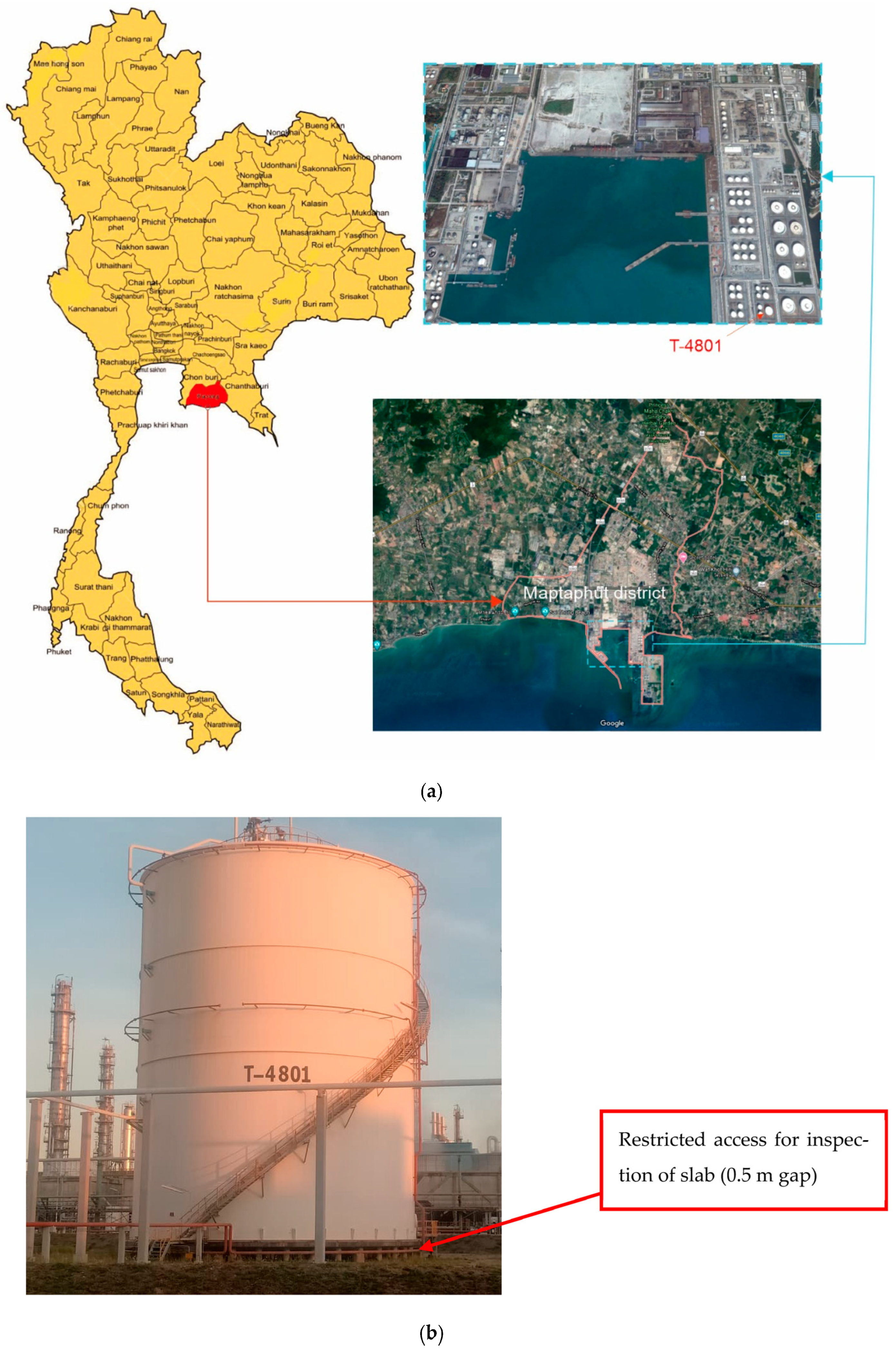
2. Case Study: Ethane Storage Tank
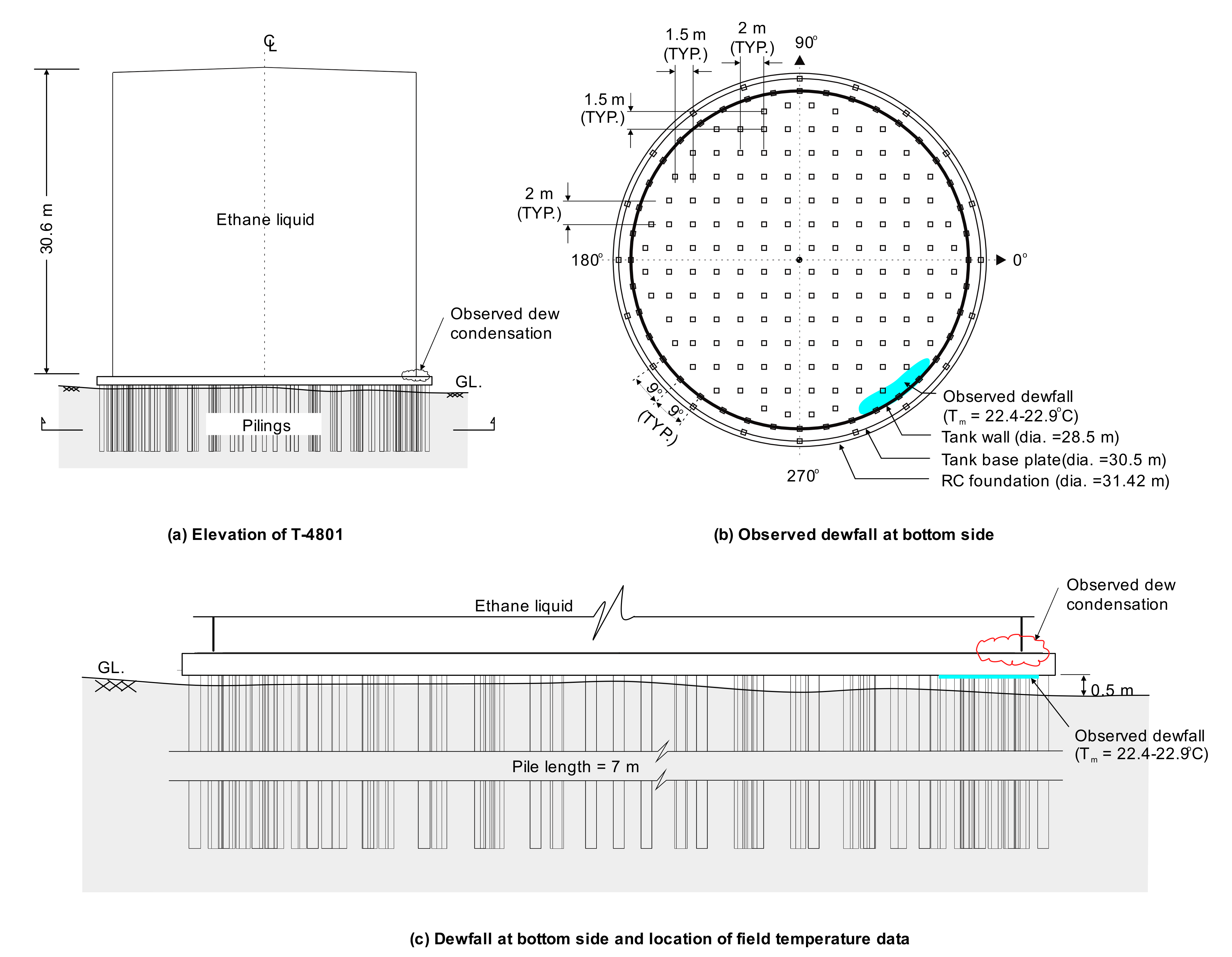
2.1. General Characteristics
2.2. Inspections and Repairs
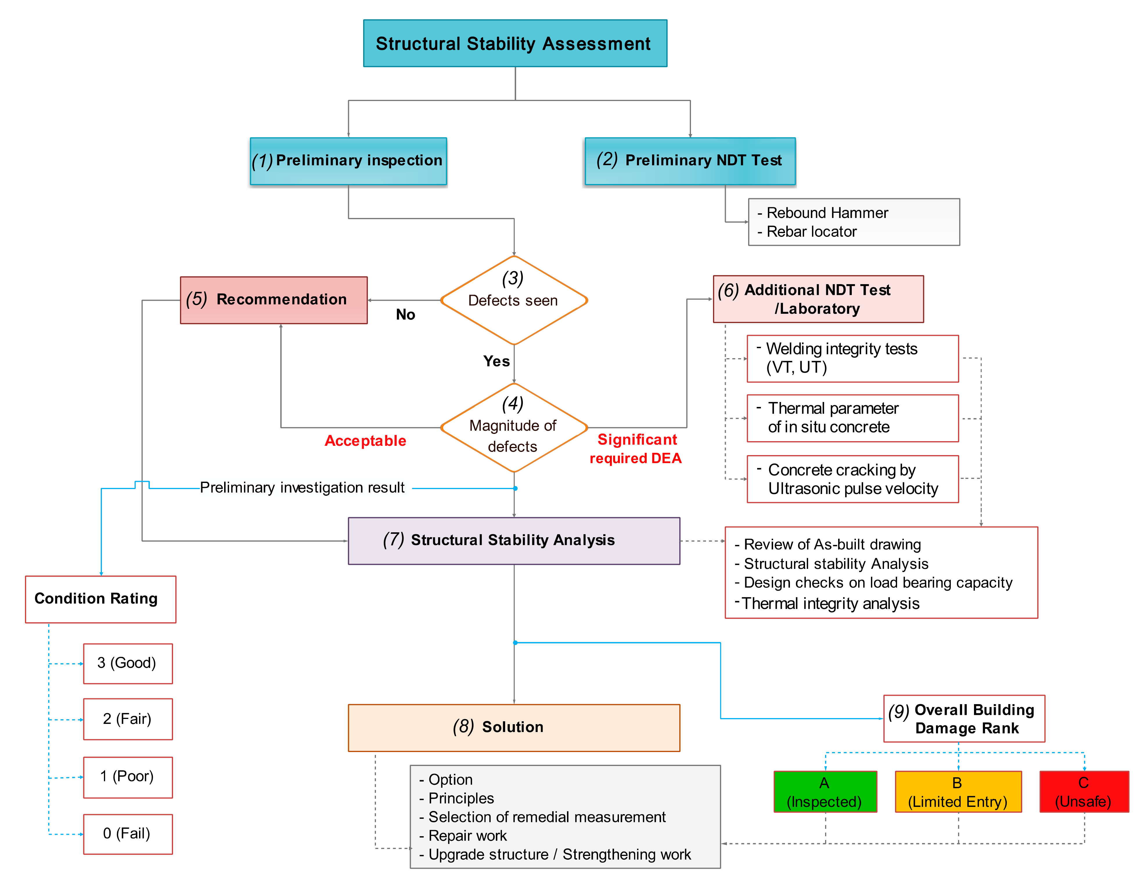
3. Phase 1: Inspection of the T-4801 Tank
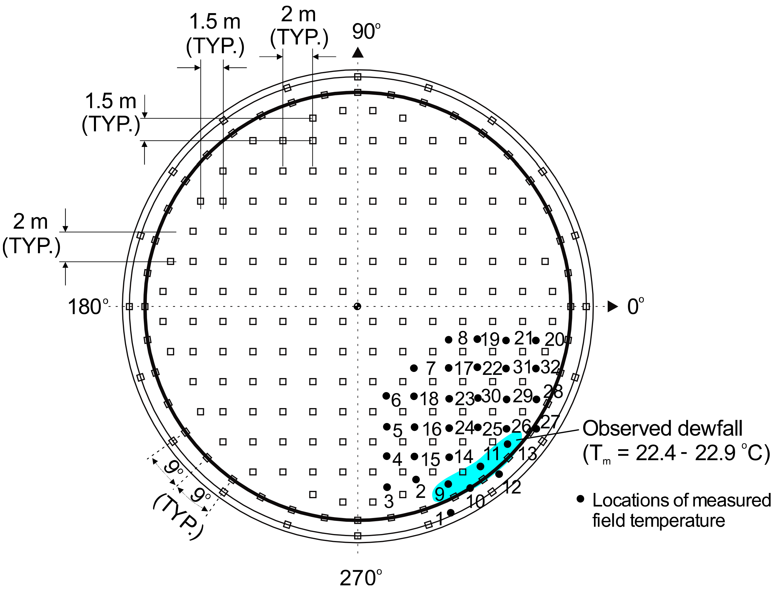
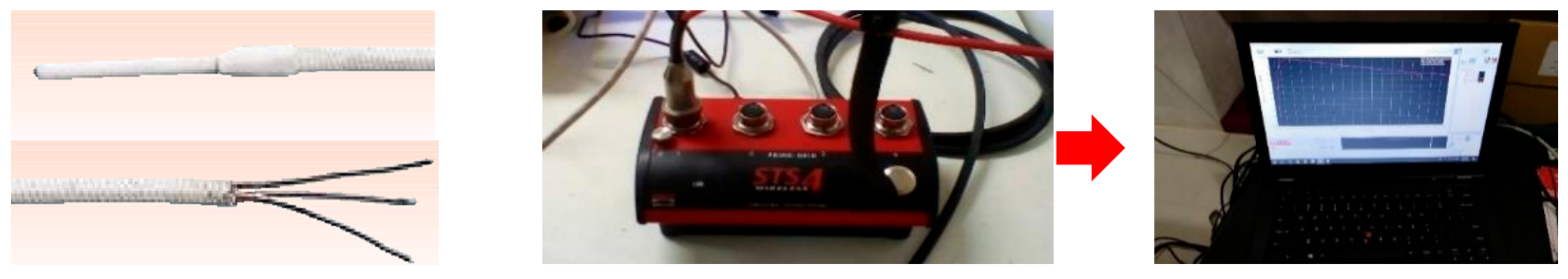
3.1. Field Temperature Measurements
3.2. Material Properties and Design Checks on Load Bearing Capacity
4. Phase 2: Thermal Integrity Analysis
4.1. Heat Transfer in Concrete Slab
4.2. FE Modelling, Boundary Conditions and Thermal Effects
5. Results and Discussion
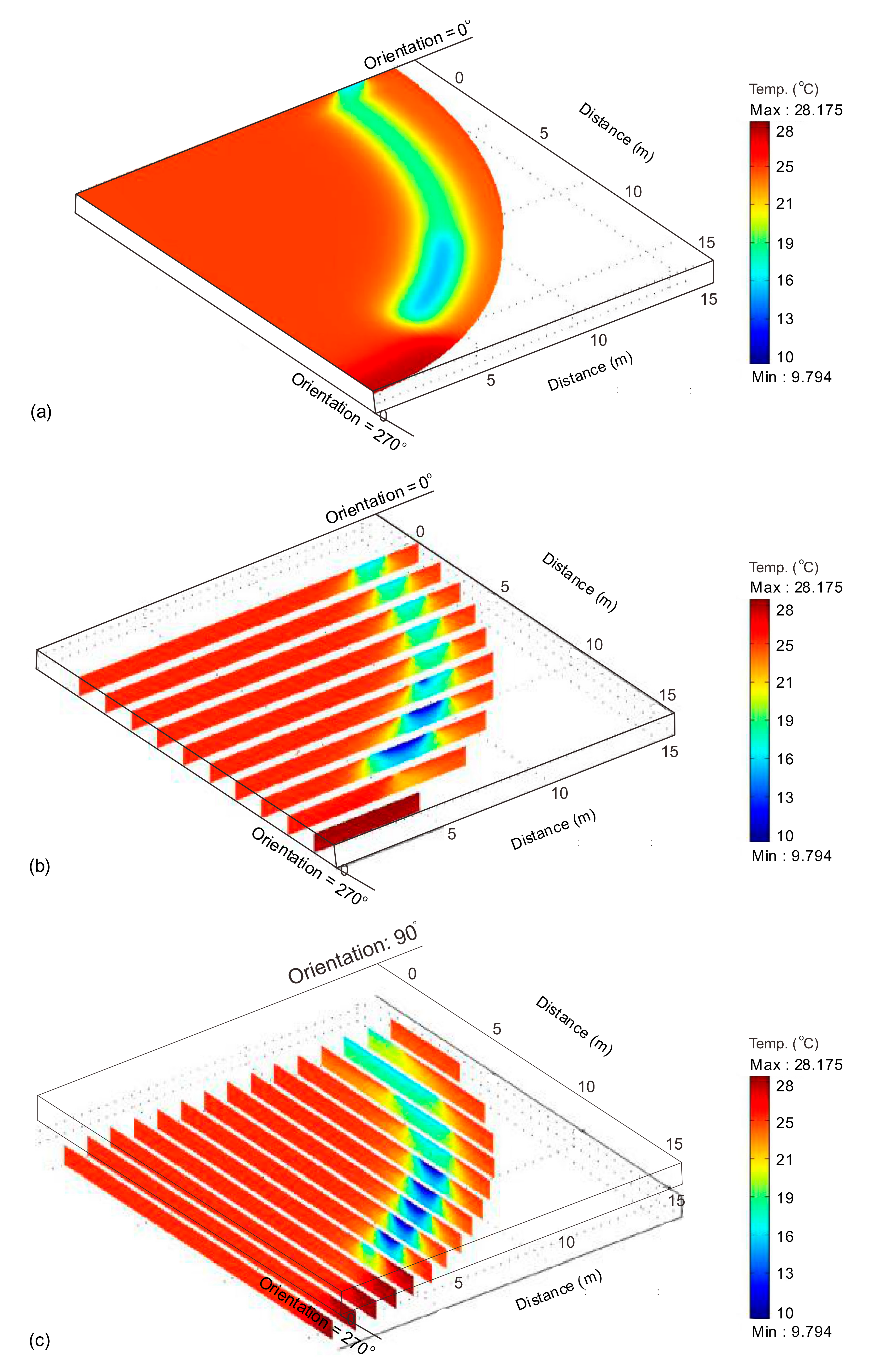
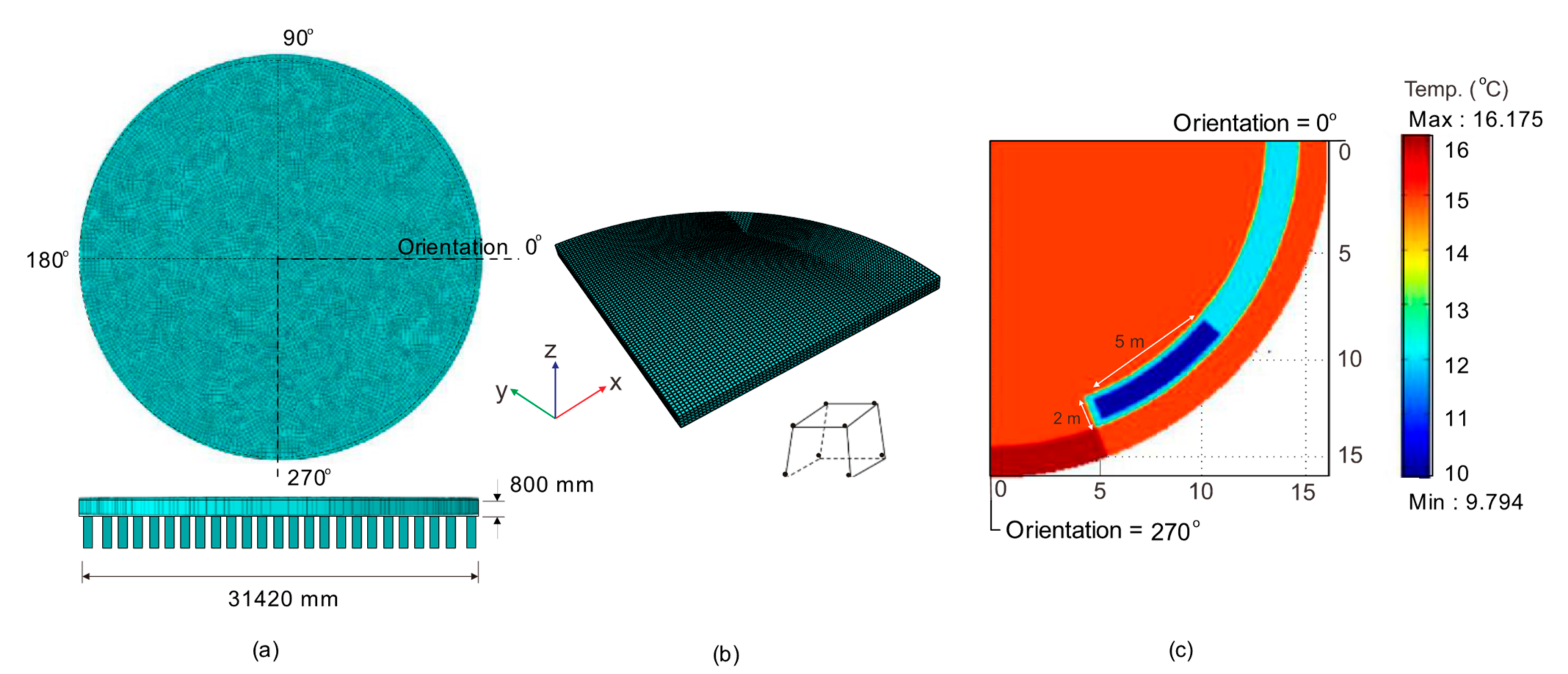
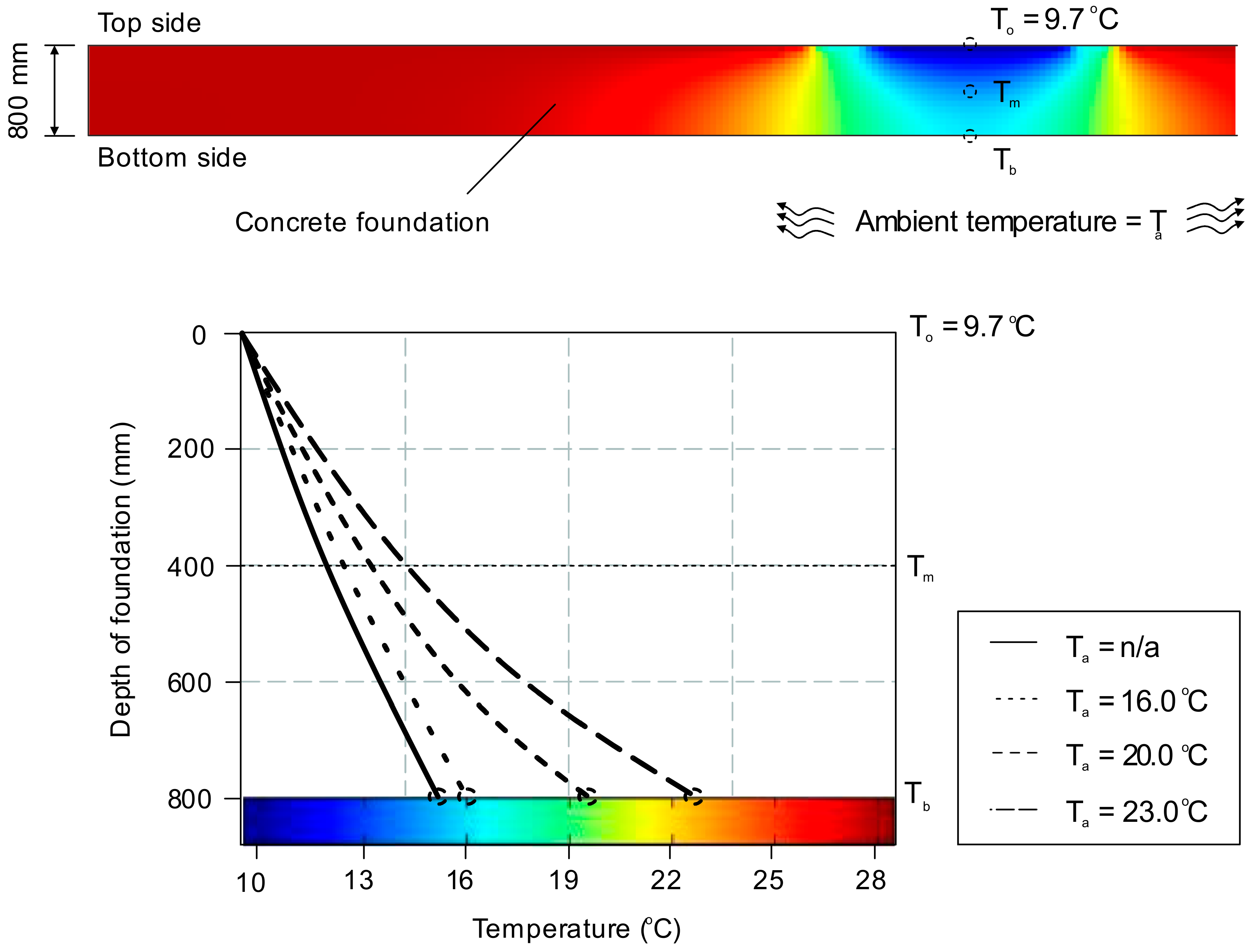
5.1. Temperature Distribution along the Concrete Foundation
5.2. Effect of Ambient Temperature
6. Conclusions
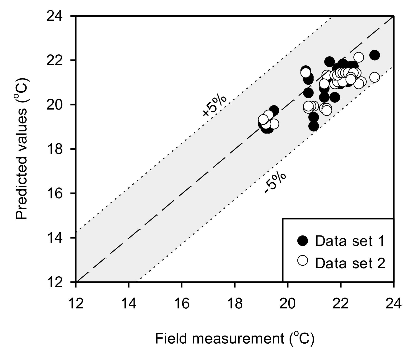
- The FE results show that the ambient temperature at the site must be taken into account in the thermal analysis of foundations, as presented in this study. When the ambient temperature recorded during the field temperature measurements was considered in the analysis, the temperatures calculated by the FE model agreed well with the measured values. The average of the ratios of measured temperatures to FE results was Exp/FE = 1.03, with a standard deviation SD = 0.03 for Dataset 1. The corresponding values were Exp/FE = 1.05 and SD = 0.04 for Dataset 2.
- The FE results also showed that the temperature progressively increases towards the bottom of the concrete slab. This means that the reinforcing bars and the inner temperature of the slab was higher than +9.7 °C, and it reached +23 °C at the bottom of the slab once the influence of environmental conditions were considered. This indicates that the simplified heat transfer equation for porous media (Equation (2)) was sufficiently accurate to model the ethane leakage in the concrete foundation. Moreover, the results also confirm that reinforcing bars can be neglected in the thermal analysis of massive concrete slabs.
- Based on the evidence from visual inspections, field measurements, nondestructive testing and results from the FE analyses, it can be concluded that the ethane leakage was unlikely to affect the mechanical properties of the concrete and reinforcing bars in the foundation. Annual inspections are being carried out to monitor the condition of the structure. The approaches, methods and techniques presented in this article proved suitable to solve the practical and scientific challenges involved in the structural assessment and repairs of this large special structure. Accordingly, they can serve as useful reference and guidance for engineers and practitioners working in the field of forensic engineering.
Author Contributions
Funding
Institutional Review Board Statement
Data Availability Statement
Acknowledgments
Conflicts of Interest
Appendix A

| Locations ID | Field Measured Data Exp. (°C) | Numerical FE Predictions (°C) for Dataset 1 | Numerical Predictions (°C) for Dataset 2 | |||
|---|---|---|---|---|---|---|
| Dataset 1 | Dataset 2 | Ta = n/a | Ta Included | Ta = n/a | Ta Included | |
| 1 | 21.0 | 19.5 | 13.7 | 19.0 | 13.7 | 19.1 |
| 2 | 21.0 | 19.3 | 14.0 | 19.4 | 14.0 | 19.5 |
| 3 | 20.9 | 19.2 | 14.3 | 19.9 | 13.7 | 19.1 |
| 4 | 20.8 | 19.1 | 14.8 | 20.5 | 13.8 | 19.3 |
| 5 | 21.4 | 23.0 | 14.9 | 20.7 | 15.3 | 21.4 |
| 6 | 21.4 | 21.5 | 14.6 | 20.3 | 15.3 | 21.3 |
| 7 | 21.8 | 21.4 | 14.7 | 20.3 | 14.2 | 19.8 |
| 8 | 23.3 | 21.5 | 16.0 | 22.2 | 14.2 | 19.8 |
| 9 | 19.3 | 21.5 | 13.6 | 18.9 | 14.1 | 19.7 |
| 10 | 19.2 | 21.0 | 13.6 | 18.9 | 14.2 | 19.9 |
| 11 | 19.2 | 20.9 | 13.7 | 19.0 | 14.2 | 19.9 |
| 12 | 19.1 | 20.8 | 13.8 | 19.1 | 14.2 | 19.8 |
| 13 | 19.5 | 20.8 | 14.2 | 19.7 | 14.2 | 19.9 |
| 14 | 20.7 | 23.3 | 15.5 | 21.5 | 15.2 | 21.2 |
| 15 | 20.8 | 22.7 | 15.2 | 21.1 | 15.8 | 22.1 |
| 16 | 20.8 | 22.8 | 15.3 | 21.2 | 15.0 | 21.0 |
| 17 | 21.5 | 22.7 | 15.2 | 21.1 | 14.9 | 20.9 |
| 18 | 21.6 | 21.8 | 15.8 | 21.9 | 15.0 | 20.9 |
| 19 | 22.0 | 23.0 | 15.1 | 20.9 | 15.0 | 21.0 |
| 20 | 23.0 | 22.1 | 15.2 | 21.1 | 15.0 | 21.0 |
| 21 | 22.3 | 21.8 | 15.2 | 21.0 | 15.2 | 21.3 |
| 22 | 22.9 | 21.9 | 15.6 | 21.7 | 15.3 | 21.3 |
| 23 | 22.5 | 22.0 | 15.7 | 21.7 | 15.3 | 21.4 |
| 24 | 22.2 | 22.1 | 15.6 | 21.7 | 15.3 | 21.4 |
| 25 | 22.2 | 22.2 | 15.7 | 21.7 | 15.3 | 21.4 |
| 26 | 22.1 | 22.3 | 15.5 | 21.4 | 15.3 | 21.4 |
| 27 | 21.9 | 22.5 | 15.3 | 21.3 | 15.2 | 21.3 |
| 28 | 23.0 | 23.0 | 15.5 | 21.5 | 15.3 | 21.4 |
| 29 | 21.9 | 22.5 | 15.6 | 21.6 | 15.3 | 21.4 |
| 30 | 22.0 | 22.4 | 15.6 | 21.6 | 15.2 | 21.2 |
| 31 | 22.1 | 22.4 | 15.7 | 21.8 | 15.1 | 21.1 |
| 32 | 22.0 | 21.4 | 15.3 | 21.3 | 14.9 | 20.9 |
| Mean (Exp/FE) | 1.43 | 1.03 | 1.47 | 1.05 | ||
| SD (Exp/FE) | 0.05 | 0.03 | 0.04 | 0.04 | ||

References
- Le May, I. Structural integrity and petrochemical industry. Energy Mater. 2008, 3, 208–219. [Google Scholar] [CrossRef]
- Mieno, F. The Eastern Seaboard Development Plan and Industrial Cluster in Thailand: A Quantitative Overview. In Aid as Handmaiden for the Development of Institutions: A New Comparative Perspective; Nissanke, M., Shimomura, Y., Eds.; Palgrave Macmillan: London, UK, 2013; pp. 81–105. [Google Scholar]
- Azadeh, A.; Salehi, V.; Arvan, M.; Dolatkhah, M. Assessment of resilience engineering factors in high-risk environments by fuzzy cognitive maps: A petrochemical plant. Saf. Sci. 2014, 68, 99–107. [Google Scholar] [CrossRef]
- Moradi, B. Risk-Based Inspection Technique and the Benefits of Its Implementation in Improving the Process Management System of Oil, Gas and Petrochemical Industries: A Review Study. J. Saf. Promot. Inj. Prev. 2020, 8, 158–171. [Google Scholar] [CrossRef]
- Si, H.; Ji, H.; Zeng, X. Quantitative risk assessment model of hazardous chemicals leakage and application. Saf. Sci. 2012, 50, 1452–1461. [Google Scholar] [CrossRef]
- Ghani, U.; Shabbir, F.; Khan, K. Effect of temperature on different properties of concrete. In Proceedings of the 31st Conference Our World in Concrete and Structures, Singapore, 16–17 August 2006. [Google Scholar]
- Lee, G.C.; Shih, T.S.; Chang, K.C. Mechanical Properties of Concrete at Low Temperature. J. Cold Reg. Eng. 1988, 2, 13–24. [Google Scholar] [CrossRef]
- Collins, A.R. The Destruction of Concrete by Frost. J. Inst. Civ. Eng. 1944, 23, 29–41. [Google Scholar] [CrossRef]
- Rostásy, F.S.; Schneider, U.; Wiedemann, G. Behaviour of mortar and concrete at extremely low temperatures. Cem. Concr. Res. 1979, 9, 365–376. [Google Scholar] [CrossRef]
- Filiatrault, A.; Holleran, M. Stress-strain behavior of reinforcing steel and concrete under seismic strain rates and low temperatures. Mater. Struct. 2001, 34, 235–239. [Google Scholar] [CrossRef]
- Liu, S.; Gu, X.L.; Huang, Q.H.; Zhang, W.P. Experimental Study on the Bending Behavior of Reinforced Concrete Beams under Super-Low Temperature. In Earth and Space 2021: Engineering, Science, Construction, and Operations in Challenging Environments; ASCE: Reston, VA, USA, 2021; pp. 3537–3544. [Google Scholar]
- DeRosa, D.; Hoult, N.A.; Green, M.F. Effects of varying temperature on the performance of reinforced concrete. Mater. Struct. 2015, 48, 1109–1123. [Google Scholar] [CrossRef]
- Montejo, L.; Asce, S.; Sloan, J.; Asce, A.; Kowalsky, M.; Kowalsky, J.; Hassan, T. Cyclic Response of Reinforced Concrete Members at Low Temperatures. J. Cold Reg. Eng. 2008, 22, 79–102. [Google Scholar] [CrossRef]
- Sargam, Y.; Faytarouni, M.; Riding, K.; Wang, K.; Jahren, C.; Shen, J. Predicting thermal performance of a mass concrete foundation—A field monitoring case study. Case Stud. Constr. Mater. 2019, 11, e00289. [Google Scholar] [CrossRef]
- Yan, J.-B.; Xie, J. Behaviours of reinforced concrete beams under low temperatures. Constr. Build. Mater. 2017, 141, 410–425. [Google Scholar] [CrossRef]
- Monfore, G.E.; Lentz, A.E. Physical Properties of Concrete at Very Low Temperatures; Portland Cement Association, Research and Development Laboratories: Washington, DC, USA, 1962. [Google Scholar]
- Li, W.; Sun, W.; Jiang, J. Damage of concrete subjected to simultaneous fatigue load and thermal effect. Mag. Concr. Res. 2012, 64, 35–42. [Google Scholar] [CrossRef]
- API 653; Tank Inspection, Repair, Alteration, and Reconstruction. The American Petroleum Institute: Washington DC, USA, 2014.
- BS EN 14620-3:2006; Design and Manufacture of Site Built, Vertical, Cylindrical, Flat-Bottomed Steel Tanks for the Storage of Refrigerated, Liquefied Gases with Operating Temperatures between 0 °C and −165 °C—Part 3: Concrete Components. British Standards Institution: London, UK, 2006.
- Kong, L.-P.; Qiao, L.; Xiao, Y.-Y.; Li, Q.-W. A study on heat transfer characteristics and pile group influence of enhanced heat transfer energy piles. J. Build. Eng. 2019, 24, 100768. [Google Scholar] [CrossRef]
- Sharifi, N.P.; Freeman, G.E.; Sakulich, A.R. Using COMSOL modeling to investigate the efficiency of PCMs at modifying temperature changes in cementitious materials—Case study. Constr. Build. Mater. 2015, 101, 965–974. [Google Scholar] [CrossRef]
- Yang, W.; Zhang, L.; Zhang, H.; Wang, F.; Li, X. Numerical investigations of the effects of different factors on the displacement of energy pile under the thermo-mechanical loads. Case Stud. Therm. Eng. 2020, 21, 100711. [Google Scholar] [CrossRef]
- Cawley, P. Non-destructive testing—Current capabilities and future directions. Proc. Inst. Mech. Eng. Part L J. Mater. Des. Appl. 2001, 215, 213–223. [Google Scholar] [CrossRef]
- Dwivedi, S.K.; Vishwakarma, M.; Soni, P.A. Advances and Researches on Non Destructive Testing: A Review. Mater. Today Proc. 2018, 5, 3690–3698. [Google Scholar] [CrossRef]
- Sinclair, T.; Malkin, R. Sensors for Ultrasonic Nondestructive Testing (NDT) in Harsh Environments. Sensors 2020, 20, 456. [Google Scholar] [CrossRef] [Green Version]
- Weber, B.; Dauti, D.; Dal Pont, S. COMSOL Implementation of a porous media model for simulating pressure development in heated concrete. In Proceedings of the COMSOL Conference 2016, Munich, Germany, 12–14 October 2016; p. 6. [Google Scholar]
- Žmindák, M.; Novák, P.; Dekýš, V.; Pelagić, Z. Finite Element Thermo-mechanical Transient Analysis of Concrete Structure. Procedia Eng. 2013, 65, 224–229. [Google Scholar] [CrossRef] [Green Version]
- Huang, H.; Garcia, R.; Guadagnini, M.; Pilakoutas, K. Effect of section geometry on development of shrinkage-induced deformations in box girder bridges. Mater. Struct. 2017, 50, 222. [Google Scholar] [CrossRef] [Green Version]
- Jana, D. Cracking of residential concrete foundations in eastern Connecticut, USA from oxidation of pyrrhotite. Case Stud. Constr. Mater. 2022, 16, e00909. [Google Scholar] [CrossRef]
- Toyo Engineering Corporation. The Thermal (Low Temperature) Effect to T-4801 Ethane Tank Foundation Due to the Leakage of Ethane; Technical Report R0 20110207; Toyo Engineering Corporation: Bangkok, Thailand, 2011. [Google Scholar]
- ASTM A240; Standard Specification for Chromium and Chromium-Nickel Stainless Steel Plate, Sheet, and Strip for Pressure Vessels and for General Applications. ASTM International: West Conshohocken, PA, USA, 2020. [CrossRef]
- ASTM E1002-11; Standard Practice for Leaks Using Utrasonics. ASTM International: West Conshohocken, PA, USA, 2018. [CrossRef]
- Imjai, T.; Tungsanga, K. Finite Element Analysis on Temperature Distribution of Ethane Storage Tank Concrete Foundation—A Case Study. In Proceedings of the International Conference on Advances in Computational Mechanics (ACOME), Ho Chi Minh City, Vietnam, 14–16 August 2012. [Google Scholar]
- International Engineering Consultants Co.Ltd. Engineering Verification of T-4801 Ethane Tank Foundation Strength; Technical Report No. IEC-T4801-01; International Engineering Consultants Co., Ltd.: Bangkok, Thailand, 2011; p. 32. [Google Scholar]
- ACI 364. 1; Guide for Evaluation of Concrete Structures Prior to Rehabilitation. American Concrete Institute: Farmington Hills, MI, USA, 1999. [Google Scholar]
- API 12C; Specification for Welded Oil Storage Tanks. The American Petroleum Institute: Washington, DC, USA, 1962.
- ACI 318-14; Building Code Requirements for Structural Concrete. American Concrete Institute: Farmington Hills, MI, USA, 2014.
- ASTM C177-19; Standard Test Method for Steady-State Heat Flux Measurements and Thermal Transmission Properties by Means of the Guarded-Hot-Plate Apparatus. ASTM International: West Conshohocken, PA, USA, 2019. [CrossRef]
- Bernuzzi, C.; Cordova, B. Structural Steel Design to Eurocode 3 and AISC Specifications: Bernuzzi/Structural Steel Design to Eurocode 3 and AISC Specifications; John Wiley & Sons: Hoboken, NJ, USA, 2016. [Google Scholar]
- Comsol Multiphysics. Comsol v. 5.4 Heat Transfer Module User’s Guide; Comsol Multiphysics: Burlington, MA, USA, 2008. [Google Scholar]
- Nield, D.A. Effects of local thermal nonequilibrium in steady convective processes in a saturated porous medium: Forced convection in a channel. J. Porous Media 1998, 1, 181–186. [Google Scholar]
- Nield, D.A.; Bejan, A. Convection in Porous Media, 4th ed.; Springer: New York, NY, USA, 2013. [Google Scholar]
- Gasch, T.; Ericsson, D. Thermally-induced cracking of a concrete arch dam using COMSOL Multiphysics. In Proceedings of the 14th ICOLD International Benchmark Workshop on Numerical Analysis of Dams, Stockholm, Sweden, 6–8 September 2017. [Google Scholar]
- Johnson, K.R. Thermal Integrity Analysis of Concrete Bridge Foundations Using COMSOL Multiphysics® Software; Comsol Multiphysics: Burlington, MA, USA, 2017. [Google Scholar]
- da Amorim Coelho, N.; Pedroso, L.J.; da Silva Rêgo, J.H.; Nepomuceno, A.A. Use of ANSYS for thermal analysis in mass concrete. J. Civ. Eng. Archit. 2014, 8, 860–868. [Google Scholar] [CrossRef]
- Isgor, O.B.; Razaqpur, A.G. Finite element modeling of coupled heat transfer, moisture transport and carbonation processes in concrete structures. Cem. Concr. Compos. 2004, 26, 57–73. [Google Scholar] [CrossRef]


| Parameter | Value | Unit |
|---|---|---|
| Concrete density, | 2300 | kg/m3 |
| Thermal conductivity, k | 2.56 | W/m·C |
| Specific heat capacity, | 0.88 | J/Kg·C |
| Coefficient of thermal expansion, | 10 × 10−6 | 1/C |
| Young modulus, Ec | 23,025 | MPa |
| Poisson’s ratio, v | 0.31 | - |
Publisher’s Note: MDPI stays neutral with regard to jurisdictional claims in published maps and institutional affiliations. |
© 2022 by the authors. Licensee MDPI, Basel, Switzerland. This article is an open access article distributed under the terms and conditions of the Creative Commons Attribution (CC BY) license (https://creativecommons.org/licenses/by/4.0/).
Share and Cite
Wattanapanich, C.; Imjai, T.; Aosai, P.; Hansapinyo, C.; Figueiredo, F.P.; Garcia, R. Thermal Analysis of a Raft Concrete Foundation: A Case Study of a Leaking Ethane Tank. Buildings 2022, 12, 889. https://doi.org/10.3390/buildings12070889
Wattanapanich C, Imjai T, Aosai P, Hansapinyo C, Figueiredo FP, Garcia R. Thermal Analysis of a Raft Concrete Foundation: A Case Study of a Leaking Ethane Tank. Buildings. 2022; 12(7):889. https://doi.org/10.3390/buildings12070889
Chicago/Turabian StyleWattanapanich, Chirawat, Thanongsak Imjai, Pakjira Aosai, Chayanon Hansapinyo, Fabio P. Figueiredo, and Reyes Garcia. 2022. "Thermal Analysis of a Raft Concrete Foundation: A Case Study of a Leaking Ethane Tank" Buildings 12, no. 7: 889. https://doi.org/10.3390/buildings12070889
APA StyleWattanapanich, C., Imjai, T., Aosai, P., Hansapinyo, C., Figueiredo, F. P., & Garcia, R. (2022). Thermal Analysis of a Raft Concrete Foundation: A Case Study of a Leaking Ethane Tank. Buildings, 12(7), 889. https://doi.org/10.3390/buildings12070889