Abstract
Rapid prediction of the post-earthquake structural damage to a region is of great importance to community relief and rescue. Detailed information on buildings in earthquake disaster areas is commonly inaccessible in the aftermath of an earthquake. Accurately assessing the seismic damage to urban buildings using limited information is significant. This study proposes a design-strength-based method for regional seismic structural damage prediction based on structural strength. Only a few basic attributes of buildings are required, including the basic building plan size, building height, construction time, and structural type. Theoretically, the method is very brief, and can be applied to all types of structures, including irregular ones, compared with other commonly used regional seismic damage prediction methods. The proposed method is validated with acceptable accuracy and efficiency compared with the refined finite element (FE) model analysis and simplified model analysis. The proposed seismic structural damage prediction method was applied to a university campus, which can serve as a simple reference for community earthquake resistance evaluation and improvement.
1. Introduction
Strong ground motion may lead to catastrophic damage in a city, and the prediction of seismic damage is essential to improve the earthquake resistance of the city. In recent years, several big cities have been hit by gigantic earthquakes. For example, the 2011 East Japan Earthquake (Mw9.0), the 2019 Albania Earthquake, and the 2020 Petrinja Earthquake in Croatia hit urban areas and caused tremendous losses and causalities. The 2011 East Japan Earthquake and the subsequent tsunami caused a direct loss of USD 211 billion [1], and 20,444 deaths [2,3]. The Albania Earthquake (Mw 5.6) caused 51 deaths and EUR 985 million in losses, accounting for 7.5% of the 2018 gross domestic product of Albania [4]. The 2020 Petrinja Earthquake in Croatia (Mw 6.4) caused 7 deaths, 26 injuries, and the displacement of thousands of people; more than EUR 10 billion in assets were destroyed in this earthquake [5]. Rapid prediction of seismic damage to buildings after an earthquake is important for urban rescue and recovery. The seismic damage to structures has conventionally been evaluated by field investigation, where experts in earthquake engineering visually inspect the damage at the site [6,7,8]. Such field investigation is time-consuming, and it often takes months to finish the inspection of the damaged area. In order to quickly assess regional earthquake damage after an earthquake, and to give guidance on post-disaster relief and recovery, a series of earthquake alert systems have been developed around the world, e.g., the ShakeMap platform of the USGS [9], and the OpenQuake platform [10]. These earthquake alert systems perform rapid structural damage assessment after an earthquake via the implementation of fragility curves. These fragility curves are generated by a number of fixed categories [11,12], considering the variation of a few attributes, which rely on a limited database.
There are two challenges for post-earthquake rapid seismic damage assessment: the first is that the method should provide accurate prediction using the low-LOD (level of detail) information of urban buildings, and the second is that the method should be computationally efficient to make rapid predictions. To solve these problems, a brief method for rapid prediction of seismic damage to buildings is proposed in this study. The subsequent sections are arranged as follows: Section 2 presents a literature review of the seismic damage assessment methods for urban buildings. Section 3 describes the proposed seismic damage prediction method. Section 4 demonstrates the validation of the proposed method on five reinforced concrete (RC) frames, compared with refined finite element (FE) model analysis and simplified model analysis. Section 5 demonstrates an application of the proposed method to buildings on a university campus. Section 6 summarizes the conclusions of the study.
2. Literature Review
Earthquakes are the most devastating disasters in urban areas, causing thousands of deaths and tremendous economic losses. A rapid and efficient method for the assessment of seismic damage to urban buildings could help with the preliminary urban damage level estimation and preparation for emergency response.
Various studies have been conducted aiming at the prediction of seismic damage to urban structures via physics-based methods. As for residential buildings, empirical fragility analysis studies are performed by using fragility curves or fragility matrices for each building type. Fragility curves or fragility matrices are mostly developed based on statistical data of damage experienced in past earthquake events. In the ATC-13 report [13], the fragility matrix was extensively used for the assessment of seismic damage to buildings in California. Empirical fragility analysis is easy, and has a wide range of applications. Biglari et al. [14] developed empirical fragility curves of steel and RC residential buildings after the 2017 Iran Earthquake (Mw 7.3). Rosti et al. developed empirical fragility curves for RC buildings based on post-earthquake damage data in Italy from 1976 to 2012 [15]. Building inventory of the empirical fragility analysis is usually classified by building typology, height, and type of design, and is especially applicable to buildings located in areas with a history of earthquake events. The capacity spectrum method (CSM) has high computational efficiency, and considers building characteristics using pushover curves. In the pushover analysis, buildings are first simplified into a single-degree-of-freedom (SDOF) model. HAZUS [16] recommends backbone curves for 36 different typical building types. For complex buildings, however, pushover models should be developed for each separate segment of the building. Therefore, for complex buildings, detailed information is needed for pushover analysis and CSM. For buildings designed to have plane, vertical, or combined plane–vertical irregularities due to architectural, functional, and distribution constraint reasons, the seismic responses are affected by the torsional effects [17]. The standard assessment procedures might not perform well on such irregular structures [18,19]. Another widely used deterministic method is quantification of the seismic performance of infrastructure using seismic damage indices (DIs). DIs can be at the level of a structural component, a structural member, a part of the structure, or the entire structure. The latter is often used for preliminary damage estimates. In the work reported in Ref. [20], the base shear of the structure was used to represent the strength capacity, in which the yield or ultimate base shear was the threshold or ultimate value of the capacity, respectively. The strength demand was calculated using an elastic response spectrum analysis.
Using simplified models—regarded as high-fidelity surrogate models of finite element models—to simulate structural seismic response has sufficient accuracy, as well as reducing the computational workload. Fishbone models [21,22] and stick models have recently been adopted as simplified methods to capture seismic response. The stick model consists of joint masses lumped at the story level or at beam–column nodes and connected by nonlinear link elements. Xiong et al. [23,24] adopted multiple-degree-of-freedom (MDOF) shear models and MDOF flexural shear models to simulate multistory and high-rise buildings, respectively. Marasco et al. [25] adopted an equivalent SDOF model to reproduce the seismic behavior of residential buildings. Gaetani d’Aragona et al. [26] developed an MDOF model consisting of a series of lumped masses connected by nonlinear shear-link elements to assess the seismic performance of RC-infilled moment-resisting frames. Bose et al. used a box model as an equivalent model of an actual building with complex floor plans, comprising four columns at the corners of the building, connected by beams and diagonal struts along the perimeter [27]. Simplified stick models of a similar type have been developed separately for a few building categories, and their accuracy relies on the calibration of the parameters. Due to the limited information on urban buildings, some of the parameters of the simplified models are determined based on statistical analysis, bringing uncertainty to the models. Sensitivity analysis methods such as the Monte Carlo method and the first-order second-moment method are often used to evaluate uncertainty in structural properties [28,29]. The uncertainty of parameters has a small influence on the analysis results when the total number of regional buildings is large. However, the uncertainty cannot be neglected for individual building analysis [30].
A number of studies and reviews have been undertaken to develop rapid methods of seismic vulnerability assessment using soft computing techniques. This kind of method develops an optimal correlation between the selected preliminary parameters and the damage states based on the data collected from field investigation by experts [31]. Soft computing techniques—including probabilistic approaches, meta-heuristics, and artificial intelligence (AI) methods such as artificial neural networks, machine learning, fuzzy logic, etc.—have been adopted to develop the correlations [32,33,34]. The application of soft computing techniques to rapid seismic vulnerability assessment could reduce the biased judgment by poorly trained engineers in field investigation, and solve the problems of inherent uncertainties in the real world. Considering the variation of design and materials in buildings’ construction, data-driven vulnerability correlations of buildings from one area may not perform well on buildings from another area [35]. For example, with vulnerability correlations developed using artificial neural networks, the correlations are first pre-tuned using a small amount of data on the predicted buildings. Conventional physics-based methods of seismic vulnerability assessment are still in use in areas where sufficient valid survey data are not available.
3. Methods
3.1. The Overstrength Factor and the Yield Strength Ratio
The overstrength factor is an indicator to represent the level of overstrength, and the yield overstrength factor can be calculated as shown in Equation (1):
where is the yield overstrength factor, is the yield base shear force, and is the design base shear force.
HAZUS [36] gives the recommended values of overstrength factors for buildings. Overstrength factors are uniquely determined by seismic design level and building inventory classification. Preliminary parameters of building inventory include basic structure type and building height. Chinese buildings can be classified in the HAZUS building inventory as described in [37], which is widely used in [24]. Lu et al. [38] derived the values of overstrength factors via statistical analysis in the structural analysis of Chinese buildings. Values of overstrength factors are provided by means of probability distributions or fitting formulas. In this study, the values of overstrength factors for buildings are adopted from the abovementioned studies.
3.2. The Proposed Design-Strength-Based Method
Due to structural overstrength, structures perform better than their performance objectives when suffering design-intensity earthquakes. In this proposed design-strength-based method for regional seismic structural damage prediction, an indicator called the seismic resistance index is proposed to evaluate the seismic capacity of structures.
The seismic resistance index is defined as shown in Equation (2):
where is the design spectral acceleration at the first period of the structure , and is the overstrength factor. Design spectral acceleration is taken as the design earthquake load for structures; thus, can represent the design strength level of the structure to some extent. In fact, structures are usually designed with redundancy in mind, so the actual strength level is higher than the design strength level. The actual strength level of the structure can be represented by the product of the overstrength factor and the design spectral acceleration , as shown in Equation (2).
Figure 1 shows a flowchart of the design-strength-based method. For a given earthquake ground motion, its earthquake load can be represented by the spectral acceleration . The natural period can be estimated with a statistical formula using a few parameters (e.g., number of stories, structure type, basic building plan sizes, and building height). The seismic design code used in the design work of the building can be determined by the construction time and seismic zone of the buildings. Then, the design spectral accelerations for different earthquake intensities are calculated using the natural period and the design spectrum in the seismic design code. Hence, the seismic capacity of the building is estimated using Equation (2). The seismic damage criteria in this method are determined using the performance objectives in the seismic design codes. When a structure suffers an earthquake load of a specific intensity level in the design code, the structure is assumed to perform no worse than the corresponding performance objectives according to the seismic design codes. Due to the structural overstrength, structures would actually perform no worse than the performance objectives when suffering ground motions of the corresponding intensity in the design codes. Therefore, the structural damage state under a certain earthquake ground motion can be predicted by comparing the spectral acceleration and seismic resistance index for different seismic design earthquake intensities.
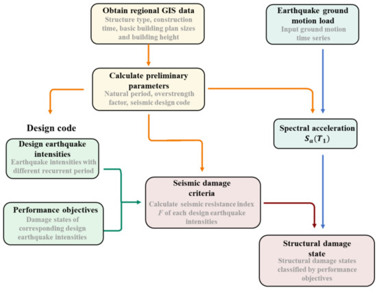
Figure 1.
Flowchart of the design-strength-based seismic damage prediction method.
For example, in the Chinese Code for Seismic Design of Buildings [39] and the Seismic Ground Motion Parameter Zonation Map of China [40], the earthquake intensities include frequent earthquakes, moderate earthquakes, rare earthquakes, and extremely rare earthquakes. The corresponding recurrence periods and performance objectives of the earthquake intensities are listed in Table 1 [39,41]. The criteria of structural damage state using the design-based method are the seismic resistance indices of four earthquake intensity levels, as shown in Table 2. To predict the damage state of a structure under a specific earthquake ground motion, the spectral acceleration at the first period of the structure is calculated. The damage state is predicted by comparing the with the thresholds in Table 2.

Table 1.
Design earthquake intensities and performance objectives in Chinese codes.

Table 2.
The design-strength-based method’s structural damage criteria.
In this study, the earthquake design intensities and performance objectives in the Chinese codes were adopted for the structural damage states. The idea of this method can also be applied to structures designed according to other seismic design codes.
4. Validation
The proposed design-strength-based method is validated in this section. Simplified models and refined FE models are used, and the seismic response of the two methods is compared with that of the proposed method. First, the seismic response of the simplified models is compared with the results of the refined FE models to verify the accuracy of the modeling of the simplified models. Then, the seismic performance of the design-strength-based method is compared with the results of the simplified models and refined FE models.
4.1. Modeling of Simplified Models
In the previous research of simplified models of buildings, multi-degree-of-freedom concentrated-mass shear (MCS) models were adopted to validate the proposed models. Figure 2 shows a flowchart of the MCS-model-based method. The initial inter-story stiffness and the mass of each story are commonly assumed to be uniformly distributed along the height of the building. The degenerated three-linearity hysteretic model is commonly used to represent the inter-story force–displacement relationships. The degenerated three-linearity hysteretic model is determined by the yielding point, peak point, and ultimate point. Thus, the accuracy of the MCS model depends on the accuracy of the values of the key points. Xu et al. [42] and Wu et al. [43] both used design strength from the seismic design code to determine the yield point. The value of the overstrength factor was determined by summarizing the statistical data of pushover analysis results of structures. Marasco et al. [44] assessed the elastic behavior of buildings through a pushover analysis, and assessed post-elastic behavior via a collapse analysis. The overstrength factor is identified according to the geometry of the structural elements of the building. Monte Carlo simulations are applied to take the uncertainties into account. A comparison between the models of different MCS-model-based methods is listed in Table 3.
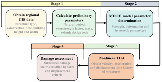
Figure 2.
Flowchart of the MCS model analysis.

Table 3.
Comparison of the parameter determination procedures of several MCS models.
The features of the proposed design-strength-based method, MCS model with THA, and refined FE model with THA are compared in Table 4. The design-strength-based method has less computational workload, and provides less detailed assessment results. The MCS model with THA has moderate computational efficiency, and assesses the seismic responses of buildings at the floor level. The refined FE model with THA has the highest computational workload, and provides the most sophisticated structural responses. Both the design-strength-based method and the MCS model with THA require less data on the structures. The design-strength-based method is applicable to all types of structures, including irregular structures, unlike the other two methods. For MCS models, parameter determination procedures should be developed separately for each structure category [23,24]. When the seismic response of a building is analyzed using the MCS models, a suitable simplified model and its parameter determination procedure for the building category should be determined first, and then the seismic response analysis should be conducted with the calculated MCS model. On the other hand, the proposed design-strength-based method is universal for buildings of all structure categories.

Table 4.
Comparison of the proposed method, MCS model with THA, and refined FE model with THA.
Five reinforced concrete frames of 3-story, 5-story, 8-story, 12-story, and 18-story designs were investigated for validation. The architectural elevations of the buildings were similar. For each building, the height of the first story and the standard floor was 4.2 m and 3.3 m, respectively. Table 5 and Table 6 show the structural features of the columns and beams of the buildings. Detailed structural information can be found in Ref. [45] and Ref [46]. The plan layout of each structure was the same, and only the number of stories was changed in the elevation layout. Figure 3 shows the plan and elevation layout of the three-story structure as an example. The structures were designed to be located on site with a shear-wave velocity in the range of (250, 500) m/s, and the design peak ground acceleration was 0.15 g, with a 10% probability of exceedance in 50 years. The first periods of the five frames in the horizontal direction were 0.58 s, 0.99 s, 1.19 s, 1.81 s, and 2.73 s, respectively. The refined FE models were built, and THA was conducted with the IDARC-2D program [47].

Table 5.
The properties of the columns.

Table 6.
The properties of the beams.
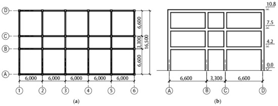
Figure 3.
Layouts of the structure (3-story frame as an example): (a) plan layout (unit: mm); (b) elevation layout (unit of elevation: m; unit of bay: mm).
Six ground motion records were selected from the PEER NGA WEST2 database (https://ngawest2.berkeley.edu/ accessed on 1 March 2020). The basic information on the ground motions is listed in Table 7. The scaled response spectra, mean response spectrum, and the target response spectrum of this site are plotted in Figure 4a,b. The selected ground motions fit the target response spectrum well. The earthquake ground motions were scaled to the earthquake intensities of the frequent earthquakes, rare earthquakes, and extremely rare earthquakes [39]. Table 8 lists the corresponding PGAs and recurrence periods of frequent earthquake intensity, rare earthquake intensity, and extremely rare earthquake intensity levels when the PGA of moderate earthquake intensity is 0.15 g.

Table 7.
Summary of ground motion records.
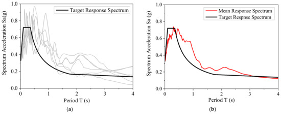
Figure 4.
Spectral characteristics of the selected ground motions: (a) each response spectrum and target response spectrum; (b) mean response spectrum and target response spectrum.

Table 8.
Earthquake recurrence periods and corresponding PGAs when the PGA of moderate earthquake intensity is 0.15 g.
Figure 5 shows the inter-story drift ratios of the MCS models and refined FE models under three earthquake intensities. GA is the refined FE model with PGA = 0.056 g; GB is the MCM model with PGA = 0.056 g; GC is the refined model with PGA = 0.316 g; GD is the MCM model with PGA = 0.316 g; GE is the refined FE model with PGA = 0.45 g; and GF is the MCM model with PGA = 0.45 g. In all 90 sets of simulation results, there are 39 sets with error in [0, 15%), 29 sets in [15%, 30%), 18 sets in [30%, 50%), and 4 sets in [50%, 70%). When the inter-story ratio of the structure is small, the results of the MCM model analysis are closer to the results of the refined FE model analysis. The reason for the difference between the MCS models and refined FE models is that the seismic response of multistory RC frames using the MCS-model-based method is determined by its inter-story force–displacement relationship, which is greatly affected by the accuracy of the parameters of the three-linearity hysteretic model. These parameters are determined by statistical analysis, and have great uncertainty [30].
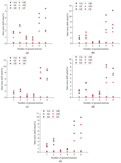
Figure 5.
Validation of the MCS-model-based method (maximum IDR): (a) 3-story structure; (b) 5-story structure; (c) 8-story structure; (d) 12-story structure; (e) 18-story structure.
4.2. Validation of the Proposed Design-Strength-Based Method
In this section, the design-strength-based method is validated using the structures used in Section 4.1. As the design-strength-based method only predicts the damage states of structures, before comparing the results of the three methods, the damage states obtained by the MCS models and refined FE models must first be assessed. The seismic damage state assessment criteria of the MCS models [24] are combined from force-based criteria and deformation-based criteria. The seismic damage state assessment criteria of the refined FE models built in the IDARC-2D program are listed in Table 9. The five damage states are divided according to the overall structural damage index in the software. The structural damage state results using the proposed design-strength-based method are shown in Figure 6. The horizontal lines in the graphs represent the seismic resistance indices of different earthquake intensities. The structural damage states are determined according to the intervals where spectral acceleration is located.

Table 9.
Damage criteria for models built in the IDARC-2D program.
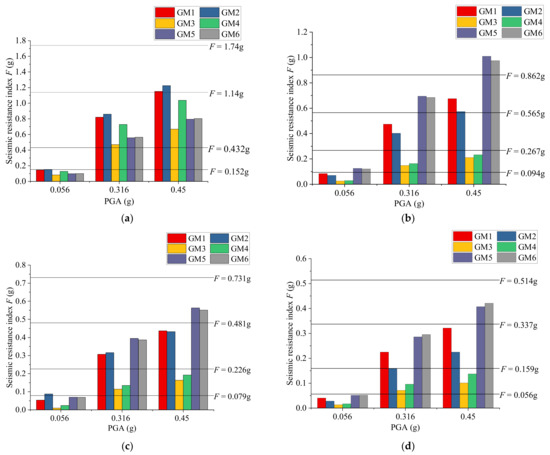
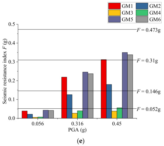
Figure 6.
Structural damage states using the proposed design-strength-based method: (a) 3-story structure; (b) 5-story structure; (c) 8-story structure; (d) 12-story structure; (e) 18-story structure.
Figure 7 shows the seismic damage state prediction results using three different methods. FE, MCM, and DS in the legend denote the refined FE model with THA, MCM model with THA, and the proposed design-strength-based method, respectively. The numbers of the tick labels denote the damage state: 1 for no damage, 2 for minor damage, 3 for moderate damage, 4 for extensive damage, and 5 for complete damage. Figure 8 shows the comparison of error between the design-strength-based method and the MCS model with THA, taking the results of the refined FE model as true values. The accuracy is represented by the dispersion coefficient in the range of [0, 1]. The method is evaluated as accurate if the dispersion coefficient is in the range of [0, 0.25), good in the range of [0.25, 0.5), bad in the range of [0.5, 0.75), and irrelevant in the range of [0.75, 1]. In this case, there are more points below the oblique dashed line, meaning that there are more cases where the error of the MCS-model-based method is greater than that of the design-strength-based method. The MCS-model-based method is usually considered to be better than the design-strength-based method, as it is able to provide more detailed information, but it also has some theoretical limitations—including the assumption of equivalent stiffness and mass along the height, and its restriction of application on regular structures. In this study—at least for validation structures—the accuracy of the two methods is comparable, even though the design-strength-based method performs better.
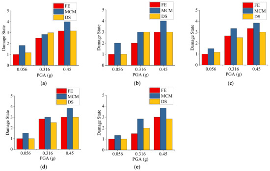
Figure 7.
Seismic damage state prediction results using the refined FE model with THA, the MCS model with THA, and the design-strength-based method: (a) 3-story structure; (b) 5-story structure; (c) 8-story structure; (d) 12-story structure; (e) 18-story structure.
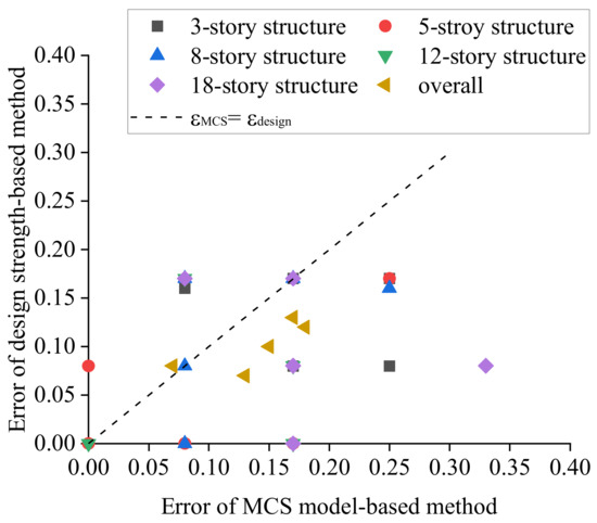
Figure 8.
Error of the design-strength-based method and the MCS model with THA, taking the results of the refined FE model with THA as true values.
5. Application
The proposed method was applied to a university campus. The structures in the university campus were designed according to the seismic design code [39], and their seismic design PGA is 0.15 g, with a 10% probability of exceedance in 50 years. The shear-wave velocity of this site is in the range of (250, 500) m/s. Figure 9 shows the plan view of the campus. Table 10 shows the basic information of the buildings on the campus, including structural type, number of stories, and construction time. Buildings built before 1989 were calculated in the same way as buildings built after 1989, because of the revision of the Chinese seismic codes.
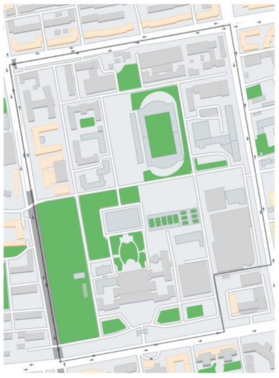
Figure 9.
Plan view of the campus.

Table 10.
Basic information of the buildings on the investigated campus.
The seismic structural damage states of buildings in the case study region were predicted using the proposed design-strength-based method. The buildings in the case study area were assumed to be designed and built in strict compliance with design codes. The natural periods of the buildings were estimated using statistical equations from the codes. According to the seismic zones and construction time, seismic design spectra for the buildings could be identified. Figure 10 shows the average damage states of the buildings under frequent, rare, and extremely rare earthquake intensities. The results demonstrate that all buildings in the case study region suffer no damage under frequent earthquake intensity, most buildings suffer minor damage under rare earthquake intensity, and most buildings suffer moderate damage under extremely rare earthquake intensity. None of the buildings suffer complete damage under extremely rare earthquakes. The seismic structural damage states demonstrate that all buildings in the case study region perform in accordance with the design performance objectives, and indicate that the proposed design-strength-based method could provide reasonable prediction of the damage state of buildings.
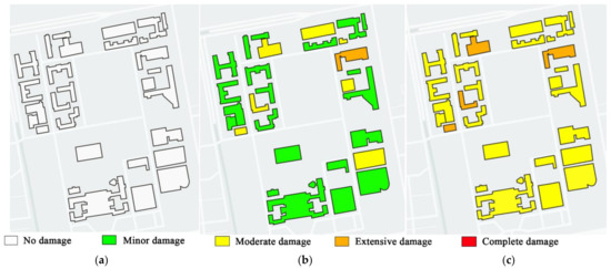
Figure 10.
Structural damage states under different earthquake intensities: (a) frequent earthquake; (b) rare earthquake; (c) extremely rare earthquake.
6. Conclusions
To predict the seismic damage to urban buildings rapidly, a brief structural design-strength-based method is proposed in this study. Refined FE element model analysis and MCS model analysis were conducted on five typical RC-frame buildings to validate the proposed design-strength-based method. The structural seismic damage prediction was implemented on a university campus to demonstrate the implementation and advantages of the proposed method. The following conclusions were obtained:
- The proposed method was proven to be both acceptably accurate and efficient by comparing with the results of the refined FE model analysis and the MCS model analysis.
- Theoretically, the proposed method can be applied to all kinds of structures, including irregular structures, unlike the MCS-model-based method.
- Based on the case study, the proposed method could provide rapid seismic damage assessment results for urban buildings using only a few preliminary parameters of the buildings.
The purpose of this work was to propose a brief method for rapid post-earthquake seismic damage prediction for urban buildings. Data used for seismic damage prediction are often inaccessible due to limited ground motion sensors and an incomplete database of urban buildings. The proposed method requires a few preliminary attributes of buildings and earthquake ground motions, which are suitable for rapid preliminary damage assessment in the earthquake alert systems, and serve as references for post-earthquake government decision making in the emergency response. The accuracy of the proposed design-strength-based method is influenced by the quality of the construction work of buildings. For buildings built in strict compliance with design codes, predicting the seismic response of the buildings using the proposed method will have considerable accuracy. For unengineered buildings or buildings with bad construction quality, the accuracy of the proposed method is reduced. The proposed design-strength-based method provides seismic damage states of buildings, but more detailed information on seismic response—including displacement and acceleration—could not be calculated using the proposed method. In the future, the prediction of seismic response—including displacement and acceleration of buildings—should be further carefully considered based on the structural characteristics. Thus, the results of the proposed seismic damage prediction method will be used not only in rapid building collapse prediction, but also to estimate seismic losses and casualties.
Author Contributions
Conceptualization, S.L. and S.Z.; methodology, S.L. and S.Z.; software, Y.L.; validation, S.L., S.Z. and Y.L.; formal analysis, S.Z. and Y.L.; investigation, S.Z.; writing—original draft preparation, S.Z.; writing—review and editing, S.L. and S.Z. All authors have read and agreed to the published version of the manuscript.
Funding
This research project was supported by the National Natural Science Foundation of China (Grant No. 41861134010) and the Natural Science Foundation of Heilongjiang (Grant No. YQ2019E021). The financial support is greatly appreciated by the authors.
Institutional Review Board Statement
Not applicable.
Informed Consent Statement
Not applicable.
Data Availability Statement
The data presented in this study are available on request from the corresponding author.
Conflicts of Interest
The authors declare no conflict of interest.
References
- Kajitani, Y.; Chang, S.; Tatano, H. Economic Impacts of the 2011 Tohoku-Oki Earthquake and Tsunami. Earthq. Spectra 2013, 29, S457–S478. [Google Scholar] [CrossRef]
- Imamura, F.; Anawat, S. Damage due to the 2011 Tohoku earthquake tsunami and its lessons for future mitigation. In Proceedings of the International Symposium on Engineering Lessons Learned from the 2011 Great East Japan Earthquake, Tokyo, Japan, 1–4 March 2012. [Google Scholar]
- Hikichi, H.; Aida, J.; Tsuboya, T.; Kondo, K.; Kawachi, I. Can Community Social Cohesion Prevent Posttraumatic Stress Disorder in the Aftermath of a Disaster? A Natural Experiment from the 2011 Tohoku Earthquake and Tsunami. Am. J. Epidemiol. 2016, 183, 902–910. [Google Scholar] [CrossRef] [PubMed] [Green Version]
- Freddi, F.; Novelli, V.; Gentile, R.; Veliu, E.; Andreev, S.; Andonov, A.; Greco, F.; Zhuleku, E. Correction to: Observations from the 26th November 2019 Albania earthquake: The earthquake engineering field investigation team (EEFIT) mission. Bull. Earthq. Eng. 2021, 19, 2993–2994. [Google Scholar] [CrossRef]
- Miranda, E.; Brzev, S.; Bijelić, N.; Arbanas, Ž.; Bartolac, M.; Jagodnik, V.; Lazarević, D.; Mihalić Arbanas, S.; Zlatović, S.; Acosta Vera, A.; et al. StEER-EERI: Petrinja, Croatia 29 December 2020, Mw 6.4 Earthquake Joint Reconnaissance Report (JRR); Report No. PRJ-2959; Natural Hazards Engineering Research Infrastructure: West Lafayette, IN, USA, 2021. [Google Scholar]
- Alcocer, S.; Behrouzi, A.; Brena, S.; Elwood, K.J.; Irfanoglu, A.; Kreger, M.; Lequesne, R.; Mosqueda, G.; Pujol, S.; Puranam, A.; et al. Observations about the seismic response of RC buildings in Mexico City. Earthq. Spectra 2020, 36, 154–174. [Google Scholar] [CrossRef]
- Galvis, F.A.; Miranda, E.; Heresi, P.; Dávalos, H.; Ruiz-García, J. Overview of collapsed buildings in Mexico City after the 19 September 2017 (Mw7.1) earthquake. Earthq. Spectra 2020, 36, 83–109. [Google Scholar] [CrossRef]
- Mehmet, I.; Ercan, I.; Haricihian, E. Application of IOS/Android rapid evaluation of post-earthquake damages in masonry buildings. Gazi Mühendislik Bilimleri Derg. (GMBD) 2021, 7, 36–50. [Google Scholar]
- Fraser William, A.; Wald David, J.; Lin, K.-W. Using ShakeMap and ShakeCast to Prioritize Post-Earthquake Dam Inspections. In Geotechnical Earthquake Engineering and Soil Dynamics IV; ASCE Library: Sacramento, CA, USA, 2008; pp. 1–10. [Google Scholar]
- Silva, V.; Crowley, H.; Pagani, M.; Monelli, D.; Pinho, R. Development of the OpenQuake engine, the Global Earthquake Model’s open-source software for seismic risk assessment. Nat. Hazards 2014, 72, 1409–1427. [Google Scholar] [CrossRef]
- FEMA. Multi-Hazard Loss Estimation Methodology HAZUS-MH 2.1 Advanced Engineering Building Module (AEBM) Technical and User’s Manual; Federal Emergency Management Agency: Washington, DC, USA; National Institute of Building Science: Washington, DC, USA, 2012. [Google Scholar]
- Martins, L.; Silva, V. Development of a fragility and vulnerability model for global seismic risk analyses. Bull. Earthq. Eng. 2021, 19, 6719–6745. [Google Scholar] [CrossRef]
- Rojahn, C.; Sharpe, R.L. Earthquake Damage Evaluation Data for California; Applied Technology Council: Redwood City, CA, USA, 1985. [Google Scholar]
- Biglari, M.; Formisano, A.; Hashemi, B.H. Empirical fragility curves of engineered steel and RC residential buildings after Mw 7.3 2017 Sarpol-e-zahab earthquake. Bull. Earthq. Eng. 2021, 19, 2671–2689. [Google Scholar] [CrossRef]
- Rosti, A.; Del Gaudio, C.; Rota, M.; Ricci, P.; Di Ludovico, M.; Penna, A.; Verderame, G.M. Empirical fragility curves for Italian residential RC buildings. Bull. Earthq. Eng. 2021, 19, 3165–3183. [Google Scholar] [CrossRef]
- FEMA. Earthquake Loss Estimation Methodology-HAZUS99; Federal Emergency Management Agency: Washington, DC, USA; National Institute of Building Science: Washington, DC, USA, 1999. [Google Scholar]
- Alecci, V.; De Stefano, M. Building irregularity issues and architectural design in seismic areas. Frat. Integrità Strutt. 2019, 13, 161–168. [Google Scholar] [CrossRef]
- López, S.; Pancardo, D.; De Stefano, M.; Ayala, G.; Alecci, V. Modified Modal Response Spectrum Analysis of Plan Irregular Highly Torsionally-Stiff Structures Under Seismic Demands. In Seismic Behaviour and Design of Irregular and Complex Civil Structures IV; Springer: Cham, Switzerland, 2022; pp. 311–320. [Google Scholar]
- Alecci, V.; De Stefano, M.; Galassi, S.; Lapi, M.; Orlando, M. Evaluation of the American Approach for Detecting Plan Irregularity. Adv. Civ. Eng. 2019, 2019, 2861093. [Google Scholar] [CrossRef] [Green Version]
- Powell, G.H.; Allahabadi, R. Seismic damage prediction by deterministic methods: Concepts and procedures. Earthq. Eng. Struct. Dyn. 1988, 16, 719–734. [Google Scholar] [CrossRef]
- Khaloo, A.R.; Khosravi, H. Modified fish-bone model: A simplified MDOF model for simulation of seismic responses of moment resisting frames. Soil Dyn. Earthq. Eng. 2013, 55, 195–210. [Google Scholar] [CrossRef]
- Soleimani, R.; Khosravi, H.; Hamidi, H. Substitute Frame and adapted Fish-Bone model: Two simplified frames representative of RC moment resisting frames. Eng. Struct. 2019, 185, 68–89. [Google Scholar] [CrossRef]
- Xiong, C.; Lu, X.; Lin, X.; Xu, Z.; Ye, L. Parameter Determination and Damage Assessment for THA-Based Regional Seismic Damage Prediction of Multi-Story Buildings. J. Earthq. Eng. 2017, 21, 461–485. [Google Scholar] [CrossRef]
- Xiong, C.; Lu, X.; Guan, H.; Xu, Z. A nonlinear computational model for regional seismic simulation of tall buildings. Bull. Earthq. Eng. 2016, 14, 1047–1069. [Google Scholar] [CrossRef]
- Marasco, S.; Zamani Noori, A.; Domaneschi, M.; Cimellaro, G.P. A computational framework for large-scale seismic simulations of residential building stock. Eng. Struct. 2021, 244, 112690. [Google Scholar] [CrossRef]
- D’Aragona, M.G.; Polese, M.; Prota, A. Stick-IT: A simplified model for rapid estimation of IDR and PFA for existing low-rise symmetric infilled RC building typologies. Eng. Struct. 2020, 223, 111182. [Google Scholar]
- Bose, S.; Stavridis, A. A computationally efficient framework for the simulation of the nonlinear seismic performance of infilled RC frame buildings. Eng. Struct. 2022, 259, 114039. [Google Scholar] [CrossRef]
- Gusella, F.; Arwade, S.R.; Orlando, M.; Peterman, K.D. Influence of mechanical and geometric uncertainty on rack connection structural response. J. Constr. Steel Res. 2019, 153, 343–355. [Google Scholar] [CrossRef]
- Bian, G.; Chatterjee, A.; Buonopane, S.G.; Arwade, S.R.; Moen, C.D.; Schafer, B.W. Reliability of cold-formed steel framed shear walls as impacted by variability in fastener response. Eng. Struct. 2017, 142, 84–97. [Google Scholar] [CrossRef] [Green Version]
- Lu, X.; Tian, Y.; Guan, H.; Xiong, C. Parametric sensitivity study on regional seismic damage prediction of reinforced masonry buildings based on time-history analysis. Bull. Earthq. Eng. 2017, 15, 4791–4820. [Google Scholar] [CrossRef]
- Harirchian, E.; Aghakouchaki Hosseini, S.E.; Jadhav, K.; Kumari, V.; Rasulzade, S.; Işık, E.; Wasif, M.; Lahmer, T. A review on application of soft computing techniques for the rapid visual safety evaluation and damage classification of existing buildings. J. Build. Eng. 2021, 43, 102536. [Google Scholar] [CrossRef]
- Allali, S.A.; Abed, M.; Mebarki, A. Post-earthquake assessment of buildings damage using fuzzy logic. Eng. Struct. 2018, 166, 117–127. [Google Scholar] [CrossRef]
- Harirchian, E.; Lahmer, T. Improved rapid assessment of earthquake hazard safety of structures via artificial neural networks. In IOP Conference Series: Materials Science and Engineering; IOP Publishing: Bristol, UK, 2020; p. 12014. [Google Scholar]
- Kumari, V.; Harirchian, E.; Lahmer, T.; Rasulzade, S. Evaluation of Machine Learning and Web-Based Process for Damage Score Estimation of Existing Buildings. Buildings 2022, 12, 578. [Google Scholar] [CrossRef]
- Xu, S.; Noh, H.Y. PhyMDAN: Physics-informed knowledge transfer between buildings for seismic damage diagnosis through adversarial learning. Mech. Syst. Signal Process. 2021, 151, 107374. [Google Scholar] [CrossRef]
- FEMA. Multi-Hazard Loss Estimation Methodology: Earthquake Model; Federal Emergency Management Agency, National Institute of Building Science: Washington, DC, USA, 2012. [Google Scholar]
- Lin, S.; Lili, X.; Gong, M.; Ming, L. Performance-based methodology for assessing seismic vulnerability and capacity of buildings. Earthq. Eng. Eng. Vib. 2010, 9, 157–165. [Google Scholar]
- Lu, X.; Guan, H. Earthquake Disaster Simulation of Civil Infrastructures, 2nd ed.; Springer: Beijing, China, 2021. [Google Scholar]
- GB50010-2010; Code for Seismic Design of Buildings. Ministry of Housing and Urban-Rural Development of P. R. China: Beijing, China, 2010.
- GB18306-2015; Seismic Ground Motion Parameter Zonation Map of China. Ministry of Housing and Urban-Rural Development of P. R. China: Beijing, China, 2015.
- Lu, D.; Zhou, Z.; Wang, C. Uniform risk-targeted definitions and decision-making of four seismic design levels con-sidering very rare earthquake. China Civ. Eng. J. 2018, 11, 41–52. [Google Scholar]
- Xu, Z.; Lu, X.; Guan, H.; Han, B.; Ren, A. Seismic damage simulation in urban areas based on a high-fidelity structural model and a physics engine. Nat. Hazards 2014, 71, 1679–1693. [Google Scholar] [CrossRef] [Green Version]
- Wu, K.; Xu, C.; Lu, X.; Sun, B. Study on backbone curves of rc frame model for simulation of city-scale seismic responses of buildings. In Proceedings of the 26th National Structural Engineering Conference, Changsha, China, 22–24 September 2017. [Google Scholar]
- Marasco, S.; Noori, A.Z.; Cimellaro, G.P. Resilience assessment for the built environment of a virtual city. In Proceedings of the 6th ECCOMAS Thematic Conference on Computational Methods in Structural Dynamics and Earthquake Engineering, Rhodes Island, Greece, 15–17 June 2017; pp. 1–13. [Google Scholar]
- Zhai, C.; Li, S.; Xie, L.; Sun, Y. Inelastic displacement ratio spectra for reinforced concrete regular frame structures. Eng. Mech. 2009, 26, 80–86. [Google Scholar]
- Sun, Y. Study on the Inelastic Displacement Estimation of Aseismatic Structures. Master’s Thesis, Harbin Institute of Technology, Harbin, China, 2006. [Google Scholar]
- Reinhorn, A.M.; Roh, H.; Sivaselvan, M.; Kunnath, S.K.; Valles, R.E.; Madan, A.; Lobo, R.; Park, Y.J. IDARC2D Version 7.0: A Program for the Inelastic Damage Analysis of Structures, User’s Guide; Multidisciplinary Center for Earthquake Engineering Research (MCEER): Buffalo, NY, USA, 2010. [Google Scholar]
Publisher’s Note: MDPI stays neutral with regard to jurisdictional claims in published maps and institutional affiliations. |
© 2022 by the authors. Licensee MDPI, Basel, Switzerland. This article is an open access article distributed under the terms and conditions of the Creative Commons Attribution (CC BY) license (https://creativecommons.org/licenses/by/4.0/).