Abstract
A concrete-filled steel tube (CFST) column permits convenient and fast construction, and its use for high-rise buildings is increasing. Meanwhile, the CFST structure has great potential for use in residence buildings, owing to its smooth evaluation. A connection for a flat CFST column has also attracted increasing attention from scholars. An innovative connection between a flat CFST column and an H beam was proposed and cyclically tested in this paper. The flat CFST column, with a width that is equal to the thickness of the partition wall, was adopted to avoid the protrusion of the column into the corner of the room. The configuration of the innovative connection was introduced, and three full-scale specimens, considering different relative positions of the beam and column, were tested under cyclic load to failure. The seismic performance, including the failure mode, ductility, etc., were revealed and evaluated. It was indicated that the plastic hinge of the connection was prominently removed outward, due to the reinforced short beam and the interior-diaphragm, verifying the reliability of the innovative connection. Furthermore, an elaborated finite element model was developed, and the results of the finite element simulation were compared with the experimental simulations. This comparison confirmed the reasonability of the developed finite element model.
1. Introduction
A prefabricated steel structure conforms to the characteristics of a green building, and has many technical advantages, such as a short design and construction period, a flexible space layout, and integrated production design. Prefabricated steel structures have become an important form in the construction industry within developed countries such as Europe, America, and Japan, and they are currently widely used in developing countries. Steel concrete composite structures have great potential for prefabrication and use in high-rise buildings, owing to their convenience for fabrication, high load-bearing capacity, and lightweight properties for construction [1,2,3]. Concrete-filled steel tubular (CFST) structures are one of the most popular forms of composite structure.
A column to beam connection is the most important factors for the safety of CFST structures. As shown in Figure 1, the connection between the CFST columns and the steel beams can be divided into three categories according to the different types of diaphragms. Typical connections include the connection with an internal-diaphragm, the connection with an outer-diaphragm, and the connection with the through-diaphragm. Doung et al. [4] investigated an internal-diaphragm joint through experimental and theoretical studies. Mou et al. [5] proposed an outer-diaphragm connection that was reinforced by an outer-annular-stiffener, and tested this connection under cyclic loading to investigate its failure modes. Di Benedetto et al. [6,7] proposed a through-diaphragm connection, adopting welded circular hollow section columns, and a new design equation was developed through theoretical analysis.
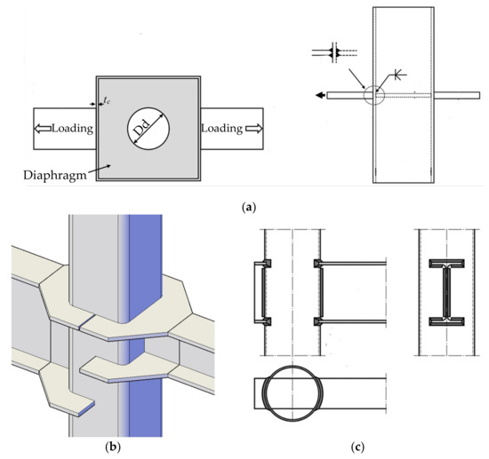
Figure 1.
Typical connection for concrete-filled steel tubular column (CFST) structures: (a) Connection with the internal-diaphragm; (b) Connection with the outer-diaphragm; (c) Connection with the through-diaphragm.
Among the CFST structures, the square columns are the most widely used, owing to their smooth evaluation for connecting with steel beams. However, the square steel columns often protrude indoors, due to the large section of the column. As shown in Figure 2, a square column cannot be completely surrounded by the partition walls, resulting in the problems such as “exposed columns” or “convex columns” in the corner of the room. This affects the architectural beauty, and reduces the indoor space. Several schemes have been proposed to solve this problem. The most effective scheme is to use flat CFST columns, where the height-to-width ratio of the cross-section is between 2 and 4 [8,9]. In this way, the width of the column is close to the thickness of the partition wall. As shown in Figure 3, a flat CFST column can be easily hidden in the wall, and a smooth evaluation can be obtained in the corner of the room. A flat CFST column structure has great potential for use in residential buildings which are more sensitive to building function and indoor space. In recent years, several scholars have attempted to study flat CFST column structures. Fu et al. [10] proposed a new type of concrete-filled rectangular steel tubular column–H-section steel beam connection with external stiffeners, as shown in Figure 4a. Zhou et al. [11] proposed π-shaped joints for flat concrete-filled steel tubular columns [Figure 4b], and the seismic performance of the joints was studied via pseudo-static experiments. Li et al. [12] presented a flat CFST column to steel beam connection, and the seismic performance of the innovative connection was revealed through an experimental study. The high-strength through-column bolts were adopted to connect the beam and the column [Figure 4c].
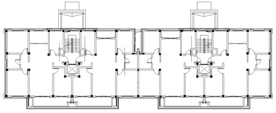
Figure 2.
Arrangement of components for traditional steel structure residential buildings.
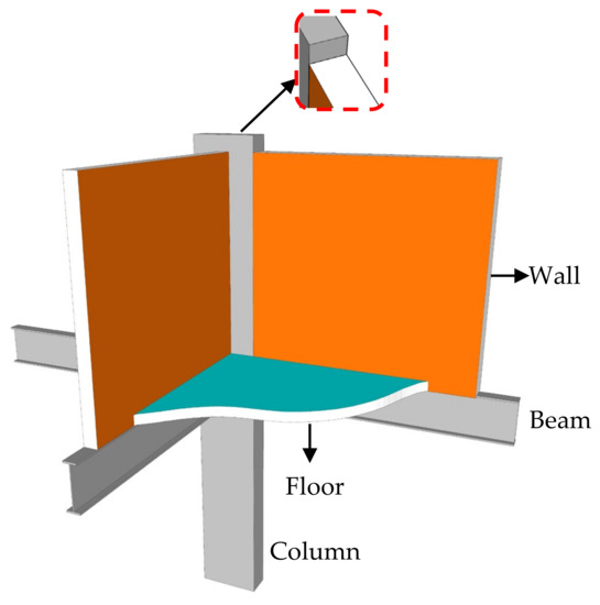
Figure 3.
Arrangement of components for the structure using flat CFST.
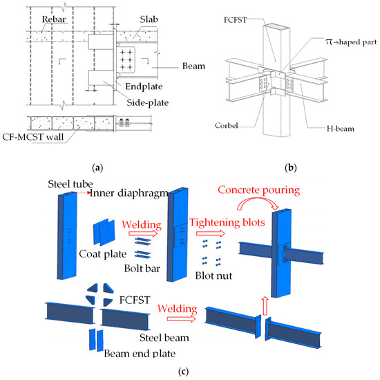
Figure 4.
Previously developed connections for a flat CFST column: (a) Connection with external stiffeners; (b) π-shaped joint; (c) Flat CFST column to steel beam joints with a stayed bolt.
However, compared with the connections for a square CFST structure, there are few connection types for a flat CFST structure. Especially, few references are available on the seismic performance of the column to beam connection in a flat CFST structure, which hinders the application of a flat CFST structure to some extent. The development of an innovative connection, as well as experimental and numerical analyses on the seismic performance of the connection is urgently needed.
In order to expand the application of flat CFST structures, an innovative connection between a flat CFST column an H beam, which can meet architectural demand and seismic design concepts, was proposed in this paper. The seismic performance of the proposed connection was studied as part of this research. Three full-scale specimens were tested under cyclic load to analyze the seismic performance of the connection, including the hysteretic behavior, ductility, energy dissipation capacity, and strain distribution. Additionally, non-linear finite element analysis using the general software ABAQUS was conducted, for a better understanding of the seismic performance of the connection. The present study will lead to a more prevalent application of the flat CFST column structures.
2. Proof for the Innovative Connection
Figure 5 depicts the details of the proposed connection between a flat CFST column and a steel H beam, and the assembly process. Interior diaphragms and a reinforced short beam were utilized. It is necessary to reserve holes in the interior diaphragm to pour the infill concrete on-site. It is worth noting that the position of the interior diaphragm should correspond to that of the flange of the steel H beam, to develop the full strength of the steel beam. A short beam rolled with H-section steel was used to transfer the plastic hinge from the column wall to the end of the beam, since the section of the short beam was designed to be stronger than the H beam. Several bolt holes were reserved on the web of the short beam to be bolted to the web of the H beam. A butt weld was adopted to connect the flange of the short beam and the H beam on-site.
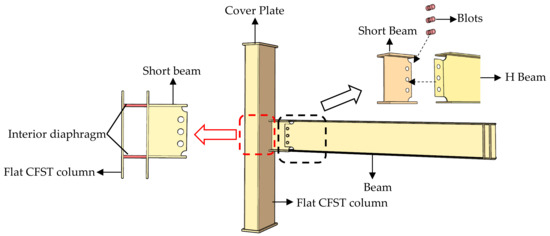
Figure 5.
Configuration of the connection.
As shown in Figure 5, the implementation of the connection can be divided into two phases. (a) Prefabrication in the factory: Bolt holes are drilled into the short beam and the H beam. Then, the internal-diaphragm with a reserved pouring hole is welded to the column wall, and the short beam is welded to the side of the column. (b) On-site assembly: The short beam and the H beam are welded at the flange, and the high-strength bolts are used to connect the web of the short beam and H beam. Finally, the concrete is poured into a flat steel tubular column. The proposed connection permits the prefabrication of components in the factory and their assembly on-site, which can reduce on-site labor and environmental pollution.
Compared with existing connections for a flat CFST column, the proposed connection in this paper is more environmentally friendly, owing to the advantage of prefabrication in the factory. In addition, the reinforced short beam is designed to move the plastic hinge outward from the column wall to the end of the H beam to obtain the well seismic performance of the connection, which will be investigated in the following section.
3. Experimental Study
3.1. Test Specimens and Material Properties
According to the conditions of the laboratory, the corner connection was selected as the prototype. A total of three full-scale specimens were fabricated, and the specimen types are shown in Figure 6. The position of the beam was considered as being the parameters between the test specimens. For specimens S-CFT-A and S-CFT-B, the beam was connected to the strong axis of the column, and for specimen S-CFT-C, the beam was connected to the weak axis of the column. All specimens tested in this study consisted of a cold-formed H-354 mm × 150 mm × 10 mm × 14 mm short beam connected to the mid-height of a cold-formed 400 mm × 180 mm × 12 mm flat CFST column. The short beam was connected with a cold-formed H-350 mm × 150 mm × 6 mm × 8 mm beam. The length of the column and the short beam were 2000 mm and 250 mm, respectively. The thickness of the interior diaphragms was 14 mm. Additional details are summarized in Figure 7 and Table 1.
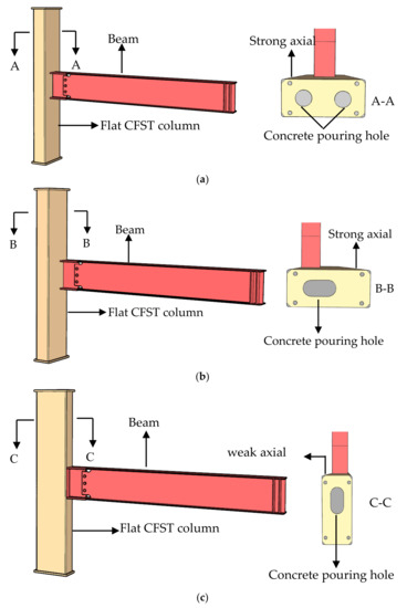
Figure 6.
Specimen types: (a) Specimen S–CFT–A; (b) Specimen S–CFT–B; (c) Specimen S–CFT–C.
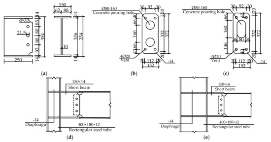
Figure 7.
Dimensions of the test specimens (unit: mm): (a) Dimensions of the short beam; (b) Diaphragm dimensions of specimen S–CFT–A; (c) Diaphragm dimensions of specimen S–CFT–B and C; (d) Profile of specimen S–CFT–A and B; (e) Profile of specimen S–CFT–C.

Table 1.
Parameters of the test specimens.
All of the steel members were manufactured from Grade Q355B steel, and C40 concrete was used to infill the flat steel tubular column. The reinforced short beam and the H beam were connected using 10.9M20 high-strength bolts with a pre-tightening force of 446 kN·m, as required by JB/T 5000.10-2007 [13]. Tensile tests of steel coupons were conducted to obtain the material properties of Q355B steel, and the material properties of the high-strength bolt were provided by the supplier. The average material properties of the concrete and steel are listed in Table 2 and Table 3. The ratio of ultimate strength to yield strength and the elongation were larger than 1.25 and 20%, respectively, which met the requirement of GB50011-2010 [14]. The compressive strength of C40 was measured using three 150 mm × 150 mm × 150 mm cubic test blocks. The average value of the measured strength (fcu) was 41.8 MPa, and the elastic modulus (Es) was 25.03 GPa.
Table 2.
Material properties of C40.
Table 3.
Material properties of steel.
3.2. Test Setup and Loading Program
Figure 8 depicts the loading devices of the test. The top and bottom of the column were clamped by the fixture to limit the axial movement of the column, and to simulate the hinged support [15,16]. The end of the beam was connected with a 500 kN actuator to apply lateral force, to simulate the seismic behavior of the connection under earthquake. Meanwhile, a lateral restraint was set on both sides of the beam during the loading, to avoid torsion of the beam.
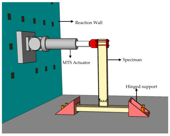
Figure 8.
Test setup.
The force-displacement hybrid control method suggested by the code AISC/ANSI 341-10 [17] was adopted in this paper. As shown in Figure 9, the first three displacement levels were applied under a load control mode. Then, the fourth to eighth displacement levels were applied under displacement control mode. The first to the third displacement levels were applied with one cycle. Three cycles were imposed at each displacement levels for the fourth to seventh levels. Finally, one cycle was imposed at the eighth displacement level. Specimens S-CFT-A and B were loaded to the eighth level, while specimen S-CFT-C was loaded to the fifth level. The displacement controlled levels was increased with an increment of yield displacement (Δy, i.e., the increment of the displacement level) of the control specimens. It was found that the Δy of the specimens was approximately 8 mm. The test was terminated when widespread fracture of the weld or the base metal occurred with reference to other similar tests [18].
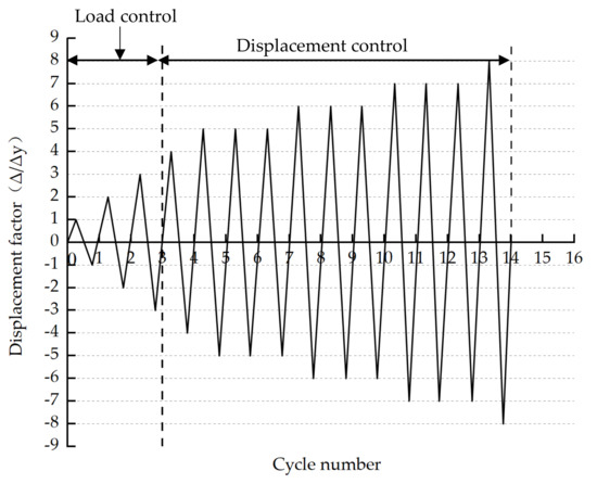
Figure 9.
Cyclic lateral loading scheme.
3.3. Instrumentation
Figure 10a depicts the location of the displacement transducer. The displacement variation of the end of the beam was recorded by the displacement transducer. The lateral force was recorded using the MTS actuator to obtain the hysteric curve of the specimens. A total of 11 strain gauges were adhered to the specimens to record the strain variations of the key positions. As shown in Figure 10b,c, the series of strain gauges of UFP and EAP were arranged on the flange of the beam and the flat CFST column, respectively. It should be mentioned that the strain gauge numbered 1,2,3 of the series UFP was located on the H beam, and the distance between them and the short beam was 30 mm, while the strain gauge numbered 4 was arranged on the reinforced short beam, as shown in Figure 10b. The series CP referred to the strain gauges on the panel zone of the connection.
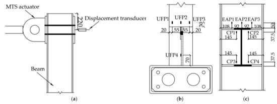
Figure 10.
Arrangement of displacement transducer and strain gauges: (a) Location of displacement transducer; (b) Location of measuring points on beam flange; (c) Location of measuring points on flat CFST column.
4. Test Results and Discussion
4.1. General Observations and Failure Mode
Figure 11 shows the typical failure modes of the test specimens. The specimens exhibited a similar damage process and failure mode. The damage process of the specimens could be identified as having three major stages: the elastic stage, the elastic–plastic phase, and the plastic failure stage. The base metal connecting the flange of the short beam and the H beam was torn at the end of the test. This may have been caused by residual stress as a result of the welding process. At the end of the loading, no damage could be found for the column, bolt, or weld between the short beam and the column.
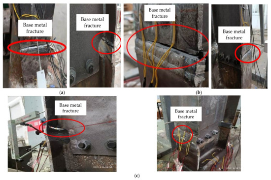
Figure 11.
Failure modes of the test specimens: (a) Specimen S–CFT–A; (b) Specimen S–CFT–B; (c) Specimen S–CFT–C.
When the displacement at the beam end was under 16 mm, specimen S-CFT-A was in the elastic stage without obvious deformation. With an increase of the displacement, cracks on the butt weld connecting the flange of the short beam and the H beam appeared and developed. The specimen reached its maximum bearing capacity (129.1 kN) at a displacement of beam end of 55.8 mm. Meanwhile, the flange of the H beam buckled. As shown in Figure 11a, the specimen was failed under the last cycle, due to the tearing of the base metal of the beam flange.
Compared with specimen S-CFT-A, the beam of specimen S-CFT-B was connected with the strong axis the column eccentrically, and a different internal-diaphragm was set in the column. However, their damage processes and failure modes were very similar. Specimen S-CFT-B was in the elastic stage before the displacement of beam end reached 16 mm. Cracks then appeared and developed near the weld connecting the flange of the reinforced short beam and H beam. The maximum bearing capacity (127.5 kN) and yielding flange of the H beam were obtained at a displacement level of 48.0 mm. Finally, the base metal was torn when the last cycle loaded, as shown in Figure 11b.
For specimen S-CFT-C, the beam was connected with the weak axis of the column. It exhibited a higher initial stiffness but a weaker lateral resistance. The specimen reached a displacement of 40 mm until the specimen was failed due to the tearing of the base metal, as shown in Figure 11c. The maximum bearing capacity (132.3 kN) was obtained at a displacement level of 31.9 mm. The results indicated that specimen S-CFT-C performed at a higher loading bearing capacity compared to specimens S-CFT-A and S-CFT-B.
4.2. Load-Displacement Hysteretic Curves
Figure 12 depicts the hysteretic curves of the specimens. The load and displacement were obtained by the actuator and the displacement transducer at the beam end, respectively. The hysteretic curves of the three specimens were plump fusiform without pinching. The hysteretic curves of the specimens were similar, reflecting that the connections had good energy dissipation capacity and ductility. In the elastic phase, the hysteretic curve of each specimen was symmetric under cyclic load. The P-Δ curve rose in a straight line, and negligible residual deformation was observed at this stage.
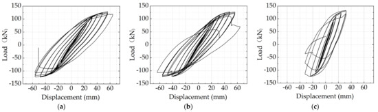
Figure 12.
Hysteresis curves of the specimens: (a) Specimen S–CFT–A; (b) Specimen S–CFT–B; (c) Specimen S–CFT–C.
In the elastic–plastic phase, part of the beam yielded. It can be observed that the area of the hysteretic curves became larger with the increasing of the cyclic load. In addition, the residual deformation increased while unloading. The specimen entered the failure phase with the progress of loading, and the load-bearing capacity decreased gradually. The lateral force dropped suddenly when a fracture of the base metal occurred and the test was terminated.
4.3. Envelope Curve
The envelope curves of all the specimens obtained from the experimental hysteretic curves are presented in Figure 13. All of the curves were S-shaped. In the elastic phase, the skeleton curves basically changed linearly. Additionally, in the elastic–plastic phase, the slope of the skeleton curve decreased due to the degradation of stiffness caused by the yield of the beam. The test was terminated when tearing of the base metal of the flange of the H beam. The envelope of specimens S-CFT-A and S-CFT-B were basically the same. This finding suggested that the eccentricity of the beam has less influence on the seismic performance of the connection compared to when the beam was connected to the strong axis of the column.
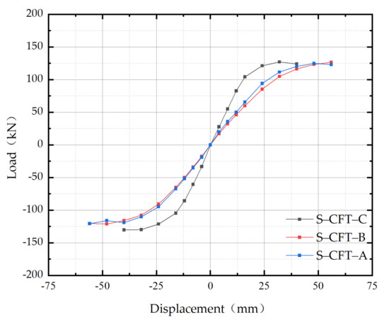
Figure 13.
Envelope curves of the specimens.
It can be observed from Figure 13 that the initial stiffness of specimen S-CFT-C was higher than those of specimens S-CFT-A and S-CFT-B. This indicated that the connecting axis of the column significantly influenced the initial stiffness of the connection. It is better to connect the beam to the weak axis of the column to obtain a higher initial stiffness. The main test results of the specimens were listed in Table 4. The yield load (Py) and the ultimate load (Pu) of the three specimens were basically the same, which suggested that the position of the beam connecting to the column had less influence on the load-bearing capacity of the connection during the case of an earthquake. However, it was obvious that the deformation capacity of specimen S-CFT-C was less than that of specimens S-CFT-A and S-CFT-B when caused by the premature fracture of the base metal of the beam flange.
Table 4.
Summary of the test results.
4.4. Ductility and Energy Dissipation
The energy dissipation coefficient (E) and equivalent viscous damping coefficient (he) are important indexes for evaluating the seismic performance of the connection. As shown in Figure 14, the two indexes can be obtained using the following equations [19]:
where, E is the energy dissipation coefficient; he is the equivalent viscous damping coefficient, and S is the area of the corresponding diagram.
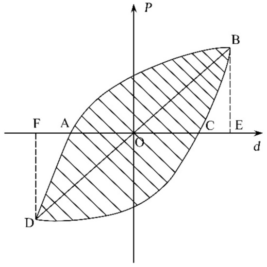
Figure 14.
P-Δ hysteresis loop of the connection.
Figure 15 shows the energy dissipation coefficient of the specimens with the increase of the loading cycle, and Table 5 lists the energy dissipation indexes of the three specimens. It was found that the energy dissipation coefficient and equivalent viscous damping coefficient of specimens S-CFT-A and S-CFT-B were basically the same, which showed that the eccentricity of the H beam had little effect on the energy dissipation capacity of the connection when the beam was connected to the strong axis of the column. However, it was obvious that the energy dissipation indexes of specimen S-CFT-C were much higher than those of specimens S-CFT-A and S-CFT-B. This may be caused by the fact that the stiffness of specimen S-CFT-C was higher than those of other specimens, resulting in better energy dissipation capacity.

Figure 15.
Energy dissipation coefficients of the specimens.
Table 5.
Energy dissipation indexes of the specimens.
The yield inter-story drift ratio (θy), the ultimate inter-story drift ratio (θu), and the angular displacement ductility coefficient (μ) of the test specimens are listed in the Table 4. The inter-story drift ratio and ductility coefficient can be obtained via the following equations:
where, Δ is the displacement at the beam end and L is the distance from the loading point to the centroid of the column.
The Chinese code for the seismic design of buildings [14] provides detailed ductility regulations for multi-layer and high-rise steel building structures: the lower limit of the elastic inter-story drift ratio (θe,l] is 0.004 rad (or 1/250), and that of the elastic–plastic inter-story drift ratio (θp,l] is 0.02 rad (or 1/50). As shown in Table 4, the yield inter-story drift ratio (θy) and the failure inter-story drift ratio (θp) of specimen S-CFT-A and specimen S-CFT-B satisfied the ductility requirement of the Chinese code GB 50010-2010 [14], and exhibited favorable deformation capacity and ductility. However, the elastic–plastic inter-story drift ratio of specimen S-CFT-C was lower than the code’s requirement. Therefore, in the actual construction, the connection with the beam that was connected to the weak axis of the column should be avoided in the high seismic zone. In addition, it can be found from Table 4 that the deformation capacities and the ductility of specimen S-CFT-A and S-CFT-B were close. This indicates that the eccentricity of the beam had less influence on the further seismic performance of the connection.
4.5. Strain Response
The measured maximum strains on both the column and the flange of the beam at each loading cycle of specimen S-CFT-A are plotted in Figure 16. As shown in Figure 16a,b, the maximum strain on the column did not reach ± 600 με, which was much less than the yield strain of the steel. From that, we can conclude that the flat CFST column did not reach its yield strain until the specimen was failed. The reason for this was that the internal-diaphragm could effectively transfer the tensile and pressure force of the upper and lower flange of the steel beam. The internal-diaphragm was helpful for increasing the strength and stiffness of the connection, and for avoiding the premature failure of the flat CFST column.
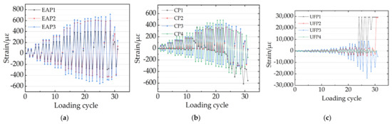
Figure 16.
Strain responses of specimen S–CFT–A during loading: (a) Strain gauges of series EAP; (b) Strain gauges of series CP; (c) Strain gauges of series UFP.
It was evident from Figure 16c that the strains of UFP1 and UFP3 were large, and the stain readings of UFP1 and UFP3 reached the yield strain of the steel at the fifth cycle and the strain reading of UFP2 reached the yield strain at the sixth cycle. The maximum strains of the strain gauge for UFP1 and UFP3 reached 24,000 με and 29,500 με when the specimen was failed. However, the strain gauge UFP4 did not reached the yielding strain until the specimen was failed. This indicated that the maximum stress of the H beam was much higher than that of the reinforced short beam. This may be caused by the fact that the section of the short beam was larger than the H beam. It can be concluded that the plastic hinge at the beam end was removed outwardly, due to the strengthening of the short beam. The strain development trend at the beam flanges of other specimens was consistent with specimen S-CFT-A and will not be discussed repeatedly.
5. Finite Element Modeling and Validation
5.1. Finite Element Modeling
In this section, general commercial finite element software ABAQUS [20] was used to establish the finite element model (FEM) of the specimens. As shown in Figure 17a,b, the simplified double line model was used to represent the stress–strain relationship of the steel, and of the high-strength bolts [21,22]. The concrete damage plasticity model was adopted in the FEM, as shown in Figure 17c,d, and the compressive strength and elasticity modulus were measured using the material property test. Poisson’s ratio of the Q355B and 10.9M20 was taken as being 0.27. The elastic behavior of the concrete was defined as the elastic-isotropic option, and the Poisson’s ratio of C40 concrete was taken as being 0.2. The compressive strength (f’c) was 48.3 MPa. Meanwhile, the compressive and tensile stress–strain relationships of the concrete were simulated using Equations (5) and (6), respectively [23]:
where, εc and σc are the compressive stain and stress of the concrete, respectively, ε0 is the strain at the maximum compressive stress (), εt and σt are the tensile strain and stress of the concrete, respectively, and fcr and εcr are crack stress and crack strain of the concrete, respectively. Figure 17c,d shows the typical tensile and compressive strain–stress relationships of the concrete material. The damage parameters in compression (dc) and tension (dt) are used to simulate the degradation of the elastic stiffness of the concrete, which can be calculated using Equations (7) and (8):
where εp is the plastic strain of the concrete in compression and the other parameters are listed in Table 6.
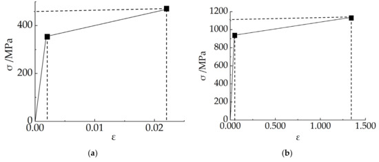
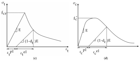
Figure 17.
Constitutive model of materials in the FEM: (a) Q355B steel; (b) 10.9M20 high–strength bolt; (c) Stress–strain relationship of the concrete in tension; (d) Stress–strain relationship of the concrete in compression.
Table 6.
Energy dissipation index of the specimens.
Figure 18 shows the typical FEM of the specimen. All of the components, including steel tubular, internal-diaphragm, concrete, blot, short beam, and H beam, were modeled using the solid element C3D8R, which is available in ABAQUS. The optimum element sizes were obtained via convergence study. The mesh size of the high-strength blots, the reinforced short beam, and columns were 5 mm. The infill concrete was modeled with a size of 25 mm, while a mesh with a size of 20 mm was used for the other parts. The embedded constraint was adopted for the interaction between the concrete and the internal-diaphragm. A tie contact was used to simulate the interaction between the flat CFST column and the short beam, to simulate the welding process. It was also used to simulate the interaction between the flange of the short beam and the H beam. Meanwhile, a surface-to-surface contact was used for the contact between other components, such as the bolt to the bolt hole, and the interaction between the web of the short beam and the H beam. Hard contact was defined in the normal direction, and the Coulomb friction model was used in the tangential direction. The Coulomb friction coefficient was set to be 0.45 [24]. A friction coefficient with 0.60 was adopted for friction between the steel tubular structure and the infill concrete [24].
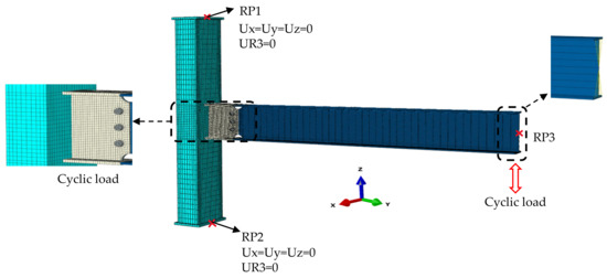
Figure 18.
Mesh, boundary conditions and loading details of the FEM.
Both ends of the column were set as hinged supports to limit the movement of the connection, which was set according to the test apparatus. The rotation around the symmetric axis of the CFST column was restricted, as shown in Figure 18.
To simulate the loading process of the test, four analysis steps were arranged in the FEM. The preload of the high-strength bolts was applied using three steps. In the first step, a smaller preload was applied to the bolt. After this, the preload was applied to the preset value, in the same manner as with the test. In the third step, the bolts were fixed at the current length. The end of the H beam was coupled to a reference point, RP3, to apply the cyclic displacement in the z-direction, as shown in Figure 18. The loading protocol was the same as the test. The Static, General Method was adopted to perform the numerical analysis. The reaction force of the coupling point was extracted to obtain the hysteretic curve of the FEM.
5.2. Validations of the Developed FEM
The hysteresis curve and skeleton curve of the specimens obtained from the test and FEA were compared in Figure 19 and Figure 20, respectively. It was found that the two curves were basically consistent for all the specimens. The comparison of the ultimate loads between the test and FEA results are listed in Table 7. The ratio between the ultimate load obtained from the FEA (Pm-FEM) to the ultimate load obtained from the test (Pm-test) ranged from 0.938 to 1.044, with a mean value of 0.974 and a coefficient of variation (COV) of 0.043. It can be concluded that the results of the simulation were in good agreement with the experimental results. The FEM developed in this paper was verified as being reasonable, and able to provide a conservative prediction of the ultimate load of the connection.
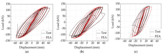
Figure 19.
Comparison of hysteresis curves between test and FEA results: (a) Specimen S–CFT–A; (b) Specimen S–CFT–B; (c) Specimen S–CFT–C.
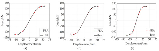
Figure 20.
Comparison of envelope curves between test and FEA results: (a) Specimen S–CFT–A; (b) Specimen S–CFT–B; (c) Specimen S–CFT–C.
Table 7.
Comparison of the peak loads between test and FEA results.
The failure modes of the specimens obtained using the FEM were compared with the test results, as shown in Figure 21. Significant stress concentrations can be found near the interface of the flange of the reinforced short beam and the flange of the H beam. This was consistent with the fracture of the base metal and the weld in this region. This comparison can be further used to verify the reliability of the FEM.
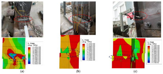
Figure 21.
Comparison of the failure model between the test and FEA results: (a) Specimen S–CFT–A; (b) Specimen S–CFT–B; (c) Specimen S–CFT–C.
6. Conclusions
In this study, an innovative connection between a flat CFST column and an H beam was proposed. Three full-scale specimens were loaded using cyclic load, to study its seismic performance. In addition, a refined FEM was established to assist with research into the connection. The following conclusions can be drawn based on the present research.
- (1)
- The hysteresis curve of the innovative connection with a reinforced short beam and an interior diaphragm is plump under an earthquake, indicating that the connection has good deformation capacity and energy dissipation capacity.
- (2)
- The failure mode of the connection is the tearing of the base metal of the flange of the H beam. The presence of the reinforced short beam and the interior diaphragm can effectively move the plastic hinge outward. The “strong column weak beam” seismic design strategy can be satisfied.
- (3)
- The seismic performances, including the hysteretic curves, ductility, and energy dissipation capacities of specimens S-CFT-A and S-CFT-B were basically the same. The eccentricity of the beam had less influence on the seismic performance of the connection when the beam was connected to the strong axis of the column.
- (4)
- When the beam is connected to the weak axis of the flat CFST column, the initial stiffness and energy dissipation capacity of the connection can be improved significantly. However, the deformation capacity and ductility were less than the connection where the beam was connected to the strong axis of the column.
- (5)
- The FEM developed in this paper was verified as being reasonable for predicting the seismic performance of the connection. The FEM can provide a conservative prediction for the load-bearing capacity of the connection.
The conclusions drawn in this paper were mainly based on an experimental study involving three specimens and their corresponding finite element analyses. A comprehensive parametric study is necessary, in order to obtain a better understanding of the seismic performance, as well as the design method of the innovative connection.
Author Contributions
Writing—review and editing, E.-F.D.; writing—original draft and methodology, Y.-H.W.; project administration and resources, Z.L.; Software and supervision, Y.-J.S.; data curation and validation, Z.W.; investigation and formal analysis, D.-B.C. All authors have read and agreed to the published version of the manuscript.
Funding
The reported research work was sponsored by Shandong Provincial Natural Science Foundation (Grant NO. ZR2020QE247), the Key R&D Project (Major Scientific and Technological Innovation Project) of Shandong Province (2021CXGC011204), the Natural Science Foundation of China (Grant NO. 51908511), and the Key Research and Promotion Project (Scientific and Technological Project) of Henan Province, China (Grant NO. 212102310286).
Institutional Review Board Statement
Not applicable.
Informed Consent Statement
Not applicable.
Data Availability Statement
Not applicable.
Conflicts of Interest
The authors declare no conflict of interest.
References
- Ali, M.M.; Moon, K.S. Advances in Structural Systems for Tall Buildings: Emerging Developments for Contemporary Urban Giants. Buildings 2018, 8, 104. [Google Scholar] [CrossRef] [Green Version]
- Shen, Y.; Tu, Y.; Huang, W. Flexural Strength Evaluation of Multi-Cell Composite L-Shaped Concrete-Filled Steel Tubular Beams. Buildings 2022, 12, 39. [Google Scholar] [CrossRef]
- Le, K.B.; Van Cao, V. Numerical Study of Circular Concrete Filled Steel Tubes Subjected to Pure Torsion. Buildings 2021, 11, 397. [Google Scholar] [CrossRef]
- Doung, P.; Leelataviwat, S.; Sasaki, E. Tensile strength and failure mechanism of internal diaphragms in wide flange beam-to-box column connections with concrete filling. J. Build. Eng. 2021, 34, 102037. [Google Scholar] [CrossRef]
- Mou, B.; Bai, Y. Experimental investigation on shear behavior of steel beam-to-CFST column connections with irregular panel zone. Eng. Struct. 2018, 168, 487–504. [Google Scholar] [CrossRef]
- Di Benedetto, S.; Latour, M.; Rizzano, G. Assessment of the stiffness of 3D cut welded connections with CHS columns and through I-BEAMS. Structures 2020, 27, 247–258. [Google Scholar] [CrossRef]
- Di Benedetto, S.; Latour, M.; Rizzano, G. Chord failure resistance of 3D cut welded connections with CHS columns and through I-BEAMS. Thin-Walled Struct. 2020, 154, 106821. [Google Scholar] [CrossRef]
- Javed, M.F.; Sulong, N.H.R.; Memon, S.A. FE modelling of the flexural behaviour of square and rectangular steel tubes filled with normal and high strength concrete. Thin-Walled Struct. 2017, 119, 470–481. [Google Scholar] [CrossRef]
- Patel, V.I.; Liang, Q.; Hadi, M.N.S. Behavior of biaxially-loaded rectangular concrete-filled steel tubular slender beam-columns with preload effects. Thin-Walled Struct. 2014, 79, 166–177. [Google Scholar] [CrossRef]
- Tong, G.; Hu, Z.; Chen, Y. Study on the moment capacity of a connection joining an I-beam to concrete-filled multicellular steel tube walls. J. Constr. Steel Res. 2021, 182, 106643. [Google Scholar] [CrossRef]
- Zhou, T.; Yang, Z.; Chen, Z. Mechanical properties of π-shaped joints of flat concrete-filled steel tubular column. J. Constr. Struct. Eng. 2021, 187, 106916. [Google Scholar] [CrossRef]
- Xu, L.; Pan, J.; Cai, J. Mechanical behavior of flat CFST column to steel beam joints under reversed cyclic loading. Eng. Struct. 2019, 198, 109540. [Google Scholar] [CrossRef]
- JGJ 82-2011; Technical Specification for High Strength Bolt Connections of Steel Structures. China Architecture & Building Press: Beijing, China, 2011. (In Chinese)
- GB50011-2010; Code for Seismic Design of Buildings. China Architecture & Building Press: Beijing, China, 2010. (In Chinese)
- El-Mandouh, M.A.; Omar, M.S.; Elnaggar, M.A. Cyclic Behavior of High-Strength Lightweight Concrete Exterior Beam-Column Connections Reinforced with GFRP. Buildings 2022, 12, 179. [Google Scholar] [CrossRef]
- Liu, X.; Cui, F.; Zhan, X. Seismic performance of bolted connection of H-beam to HSS-column with web end-plate. J. Constr. Steel Res. 2019, 156, 167–181. [Google Scholar] [CrossRef]
- AISC/ANSI 341-16; Seismic Provisions for Structural Steel Buildings. Chicago American Institute of Steel Construction: Chicago, IL, USA, 2016.
- Ahmadi, M.M.; Mirghaderi, S.R. Experimental studies on through-plate moment connection for beam to HSS/CFT column. J. Constr. Steel Res. 2019, 161, 154–170. [Google Scholar] [CrossRef]
- Calado, L.; Proenca, J.M.; Espinha, M. Hysteretic behavior of dissipative welded fuses for earthquake resistant composite steel and concrete frames. Steel Compos. Struct. 2013, 14, 547–569. [Google Scholar] [CrossRef]
- ABAQUS; User Manual Version 2010. DS Simulia Corp.: Providence, RI, USA, 2013.
- Tort, C.; Hajjar, J.F. Mixed Finite-Element Modeling of Rectangular Concrete-Filled Steel Tube Members and Frames under Static and Dynamic Loads. J. Struct. Eng. 2010, 136, 654–664. [Google Scholar] [CrossRef]
- Ahmed, M.; Liang, Q.; Patel, V.I. Experimental and numerical investigations of eccentrically loaded rectangular concrete-filled double steel tubular columns. J. Struct. Eng. 2020, 167, 105949. [Google Scholar] [CrossRef]
- Ansari, M.; Jeddi, M.Z.; Badaruzzaman, W.H.W. A numerical investigation on the through rib stiffener beam to concrete-filled steel tube column connections subjected to cyclic loading. Eng. Sci. Tech. Inter. J. 2021, 24, 728–735. [Google Scholar] [CrossRef]
- Fan, J.; Zhao, J. Experimental investigation and analytical modeling of steel beam-to-CFDST column connection. J. Struct. Eng. 2022, 190, 107164. [Google Scholar] [CrossRef]
Publisher’s Note: MDPI stays neutral with regard to jurisdictional claims in published maps and institutional affiliations. |
© 2022 by the authors. Licensee MDPI, Basel, Switzerland. This article is an open access article distributed under the terms and conditions of the Creative Commons Attribution (CC BY) license (https://creativecommons.org/licenses/by/4.0/).