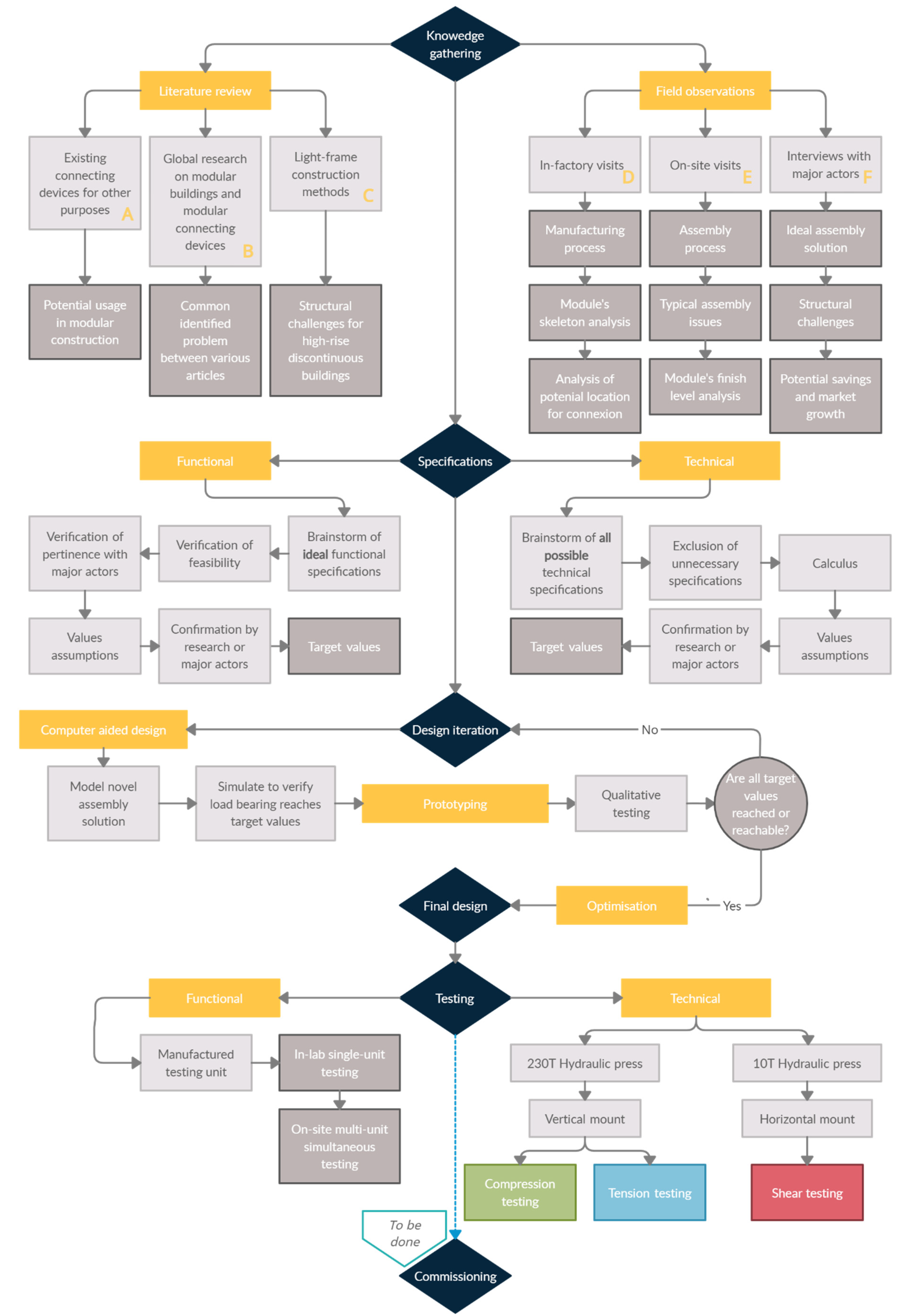
3. Results
3.1. Description of the Problem
Field observations were performed in three different factories and at a construction site in Quebec City where a four-storey, 24-unit multiresidential modular building was under construction. These four sources of knowledge gathering are detailed in
Section 3 and led to the following observations.
Currently, during modular building assembly, every existing connection relies on a multistep process. When the upper module is completely laid down on the lower module, workers must enter the building at various connection access points and fix screws and bolts to ensure a permanent link between the modules. This operation is time-consuming. It has been observed that workers can easily spend an hour securing the connections before another module can be assembled. Since buildings are subjected to different types of loading (compressive, tensile, shear) over the course of their existence, connecting points must restrict any displacement caused by external loadings, which explains the need to add axial fixtures on the vertical load paths. For corner-supported modules, all four corners in each module have to be left unfinished upon delivery (e.g., drywall not installed, plaster joints not done, and paint not applied) to allow working space to install additional fixtures. In the case of a longer module, connection points in need of additional work can number up to eight. This leads to a high percentage of work left to be completed on-site rather than in the factory, consequently reducing the benefits of off-site manufacturing.
Once internal connections are completed, further steps are required at the exterior surfaces. Depending on climate, usage, and materials, the vertical and horizontal edges of adjoining modules have to be finished to integrate isolation, diaphragm continuity, air barrier, vapour barrier, sound barrier, and siding. In Quebec, most off-site manufacturers create light-framed wood modules [
9,
10,
22,
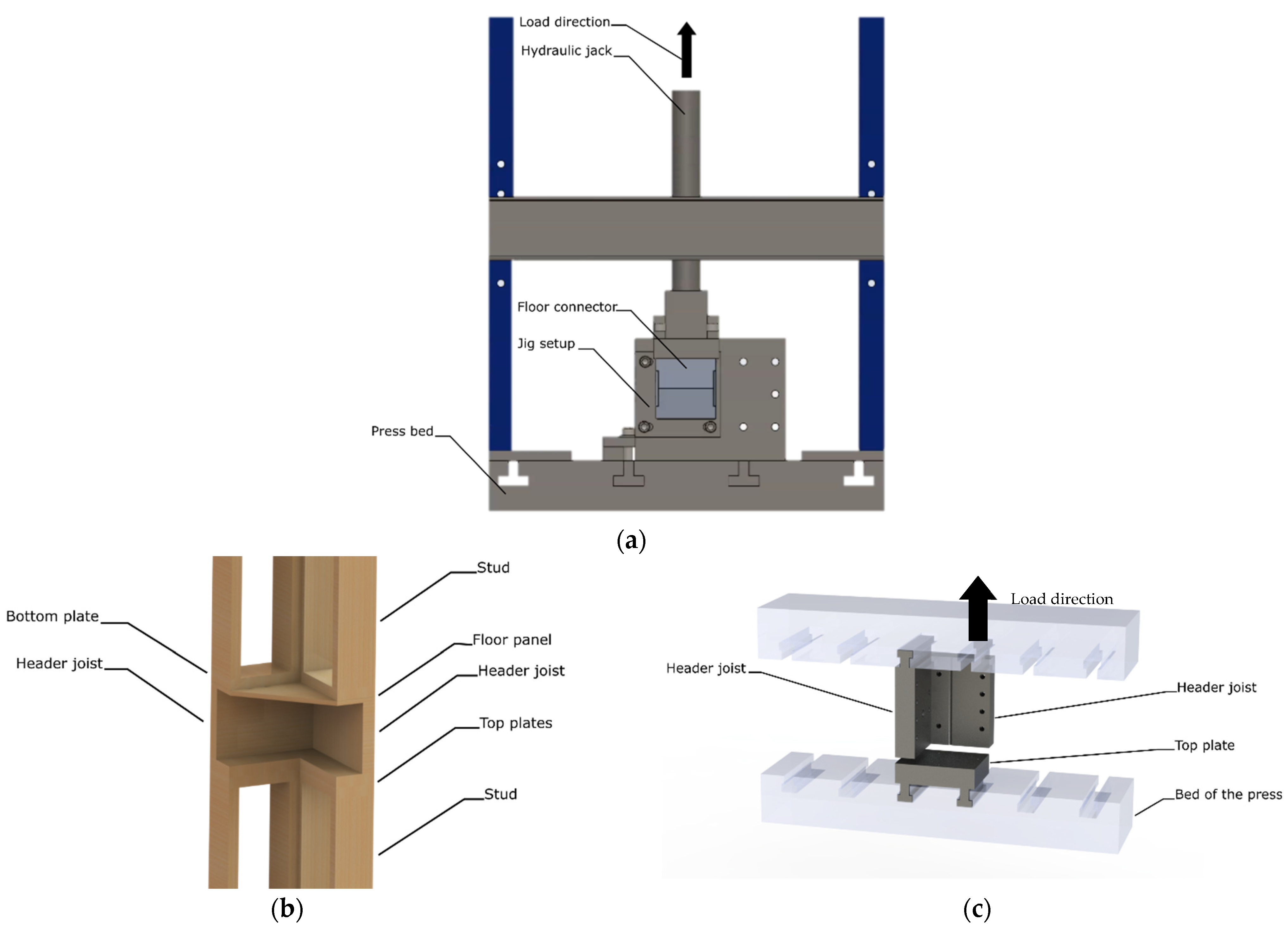
23]. Typical modules have to be freestanding and show a high level of rigidity for transportation and handling needs. From bottom to top, the floor is generally made of an engineered-wood perimeter acting as header joists. They contain the floor joists and allow for electricity and plumbing services. This assembly is topped with wood panels, for which the structural role is to act as a diaphragm, controlling shear in the floor plane. Typical walls are mounted on top of the wood panels, beginning with bottom plate and studs, up to the top plate. Again, vertical wood panels are fixed at the outer surfaces of the walls to oppose shear forces. Insulation, plumbing, and electricity are housed between studs, some sheeting is added to act as a vapour barrier, and the drywall is finally installed. The external surface of the top headers either becomes the sitting surface for the roof joists and roof ruts, or the sitting surface for the next floor header joists. In multistorey cases, the common surface between the top header and the header joist is where connection has to take place in order to transfer loads between stacked-up modules.
For security purposes during building assembly, for every module added, all of the connecting steps mentioned above have to be completed before lifting the next module. Indeed, if load-resisting systems are not deployed at each module addition, the building is subject to collapse at any moment. This induces wait times for many workers on-site which reduces the overall efficiency. Multistorey buildings that comprise numerous modules may be manufactured by a combination of independent manufacturers because of limited storage and production capacities. Since no standard connecting device exists, manufacturers must agree on a connection technique and modify their production lines accordingly. Since this often differs from their regular technique, it becomes a potential source of errors and complications. The cost and delays induced by this design modification phase are of great importance and often discourage promoters from choosing this construction method. This highlights the importance of designing a standard connecting device that can easily be implemented in light-framed modules regardless of the manufacturer.
3.2. Proposed Novel Connecting Device
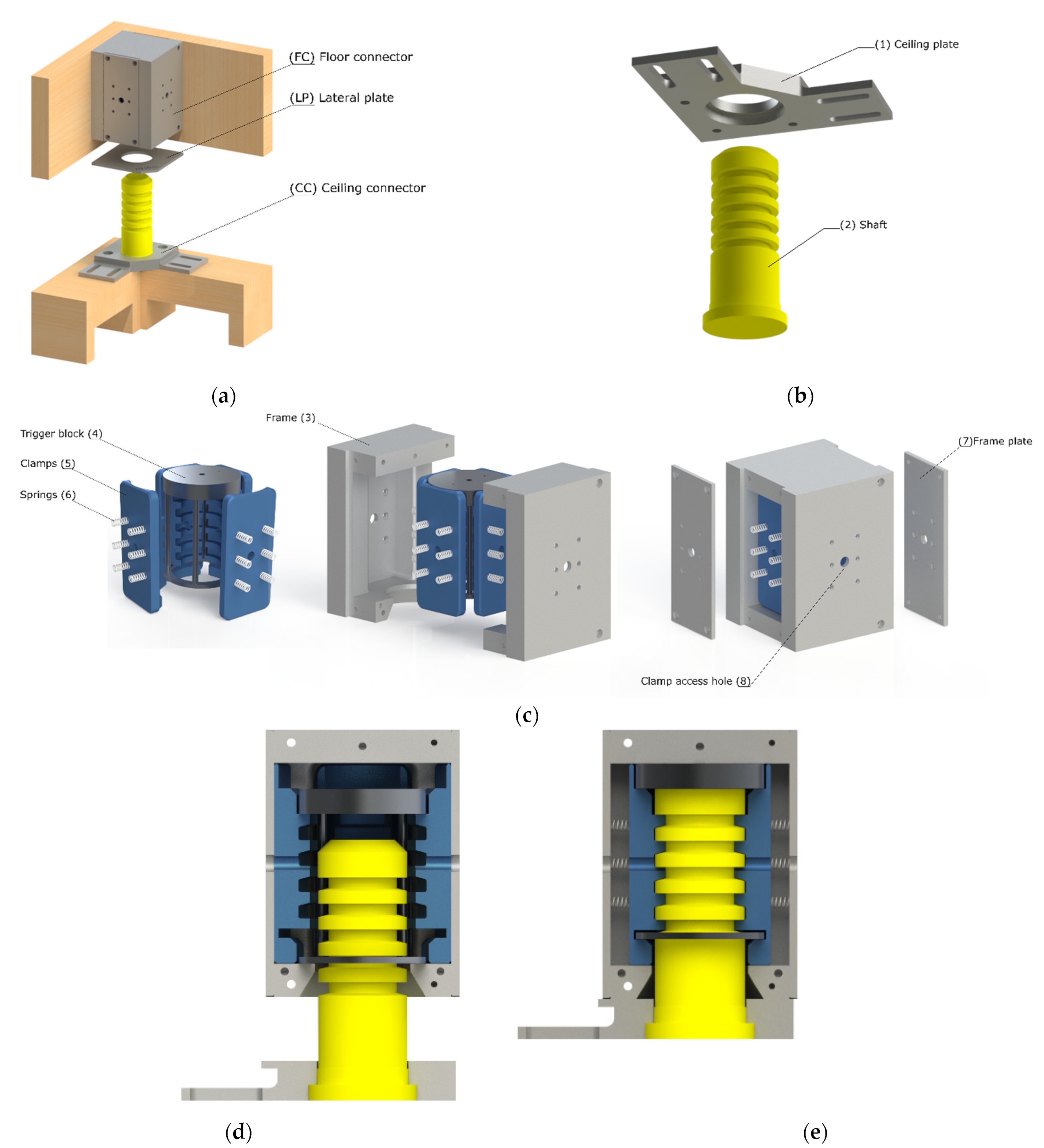
The proposed NCD is composed of a lateral plate (LP) and two distinct assemblies, respectively named floor connector (FC) and ceiling connector (CC), presented in
Figure 3a.
Figure 3b presents the CC in an exploded state, and
Figure 3c presents the FC in an exploded state with local enlarged views of small subassemblies.
Figure 3d presents a cross section of the assembly prior to connection, and
Figure 3e a cross section of the assembly when fully connected.
The CC is composed of a ceiling plate (1) which ties down onto the top wall plates. The ceiling plate (1) has a central cavity into which a serrated shaft (2) is inserted. The FC assembly is made of a frame (3) fixed to the floor beams. The frame (3) has in its centre a circular opening slightly greater than the diameter of the shaft (2), with which is aligned a trigger block (4) of cylindrical shape, almost entirely hollowed out except for a lower ring, columns on the periphery and a solid section at the top. This trigger block (4), when in the initial position (low position), geometrically constrains (by its diameter) the four clamps (5) away from the centre of the assembly. The clamps (5) have a geometric profile complementary to that of the shaft (2), and are linked to the frame (3) via springs (6) in compression which tend to push the clamps (5) towards the centre. When the assembly begins, the shaft (2) progresses in the cavity of the frame (3) until it reaches the upper section of the trigger block (4). The trigger block (4) is then driven in movement upwards until both cylindrical parts of the trigger block (4) reach the two cavities in the clamps (5) intended to accommodate the lower ring and the upper section of the trigger block (4). The clamps (5) are then geometrically free to move towards the centre to interlock with the shaft (2) and to create a final connection. The assembly is then completed, and the FC cannot be separated from the CC by tension, nor by compression, nor by shear. The frame plates (7) complete the assembly and close the cavities for two of the four clamps (5). The frames (2) and the frame plates (7) have four clamp access holes (8) used to reach the clamps (5). When screwing a safety bolt into a clamp access hole (8), the head of the bolt is pushed onto the frame (3) while the threads of the bolt apply a pulling motion on the clamp (5). This eliminates the contact between the shaft (2) and the clamp (5) to allow unlocking for end of building life or to undo an unwanted connection.
While the CC and FC ensure a vertical permanent linkage between modules on two separate floors, linkage between adjacent modules also has to be ensured. Hence, extra space was designed for an additional part that would allow horizontal linkage between modules, namely LP. Sendanayake [
19] showed that the composition of this lateral part for linkage must be well-designed and optimised to ensure compliant behaviour and to smoothly transfer shear loads between adjacent modules. Hence, the detail of the plate still has to undergo a complete analysis and rigorous design process, and will be covered in future research. With regards to the assembly process of this part, it was designed to be manually added directly on-site after each module addition, prior to installing the next storey. The plate is designed to require no fastening operations, since its positioning will be secured by the weight of the upper modules. Hence, the workers will only have to place the plates.
3.3. Potential Productivity Gain
To assess the economic advantages of using an automated connecting device, a comparison was established between the costs of erecting a multistorey modular building with and without the NCD. Current practice for single-home modular buildings allows for an off-site finish level of approximately 90% [
24]. For multistorey modular buildings, the actual obtainable off-site finish level without NCD is approximately 60%, since floor panels and drywalls have to be left opened at connecting points (four to eight per module) [
9,
10,
22].
In order to analyse the losses induced by these on-site finishing steps, conventional construction and off-site construction were compared. Several studies have indicated that modular construction can reduce the construction period by 50–60% compared to the traditional method [
6,
23]. From field observations, it can be estimated that the time needed to do the same job on-site will take twice the time needed to do it in the factory, attributable to off-site organisation and easy material supply [
25,
26]. Knowing that rates are, at the time of writing, 65
$/h for traditional construction and 32
$/h for off-site construction in Quebec, a one-hour job will cost 32
$ to do off-site, and 130
$ to do on-site [
9,
10]. This corresponds to a 400% cost increase for any specific job. This highlights the need for a NCD that maximises the off-site completion of modules.
The following economic scenario illustrates the potential productivity gain of the automated NCD. A 500 square foot module can present a maximal off-site finish level of 90% with a total off-site labour cost of 20,000
$ [
10]. Hence, off-site, the completion of the module, labour-wise, costs 222
$ for each 1% completed. Following the 400% cost increase, this means 1% module completion labour-wise costs 888
$ on-site, compared to 222
$ off-site.
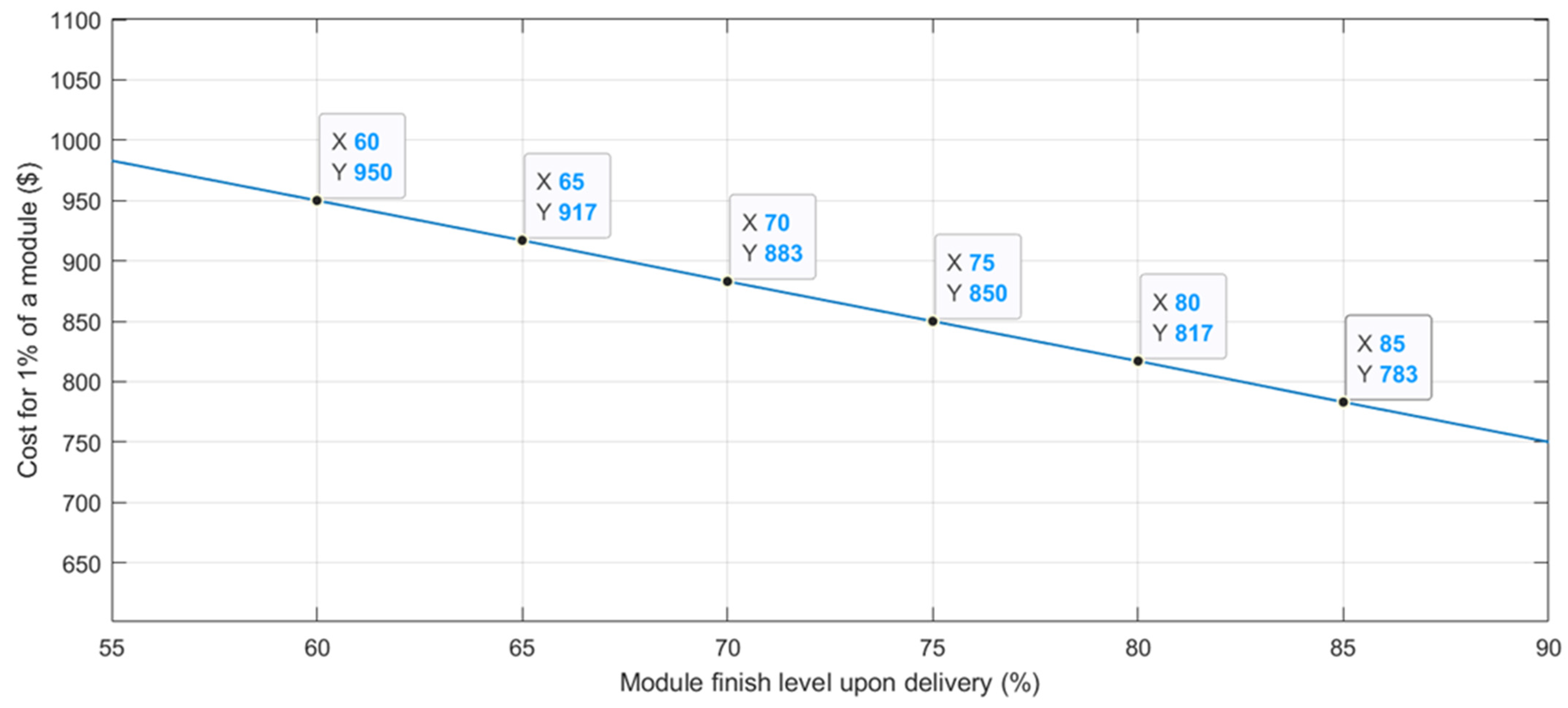
Table 3 and
Figure 4 below illustrates the linear effect of these cost variations. Of course, this linear effect could show exponential behaviour in highly repetitive buildings, since workers show a greater efficiency when repeating the same operations.
Figure 4 presents the total cost per 1% of a 500 ft
2 module as function of its finish level upon delivery. The total cost includes the typical fixed-costs of 46,111
$ per module (independently of the finish level since materials and transport represent most of the fixed-costs), the off-site labour costs, and the on-site labour costs. This highlights that a 90% completed module presents a typical total cost of 75,000
$, whereas a 60% completed module presents a typical total cost of 95,000
$. The balance of the plant is not included, and nor are the assembly costs, the connection to municipal services, excavation, or any other cost unrelated to the modular manufacturing.
Through the development of this NCD, a 20% increase in completion level upon delivery is expected, which corresponds to an equivalent of 13,333$ of savings on the labour cost for every module according to our hypothesis. Many other additional costs are expected when delivering modules at a low finish level, such as supply of material and tools on-site, labour management, risk management, and more. The costs of the connectors themselves are not included, but are expected to be offset by the structural changes induced by their use, such as the elimination of nails, metallic plates, and bands, for example.
It is also of interest to analyse the savings associated to a more efficient assembly process on-site. A typical 8 h day of assembly involves ≈15 workers (65$/h), one crane (≈6,000$/day), and ≈four truckers (≈45$/h); thus, every assembly day costs 15,240$. Without the NCD, one module is assembled every hour, corresponding to 1905$ per module assembled. With the NCD, it is expected that tasks can be done simultaneously and the connection does not involve any manipulation, thus reducing the assembly time to 15 min per module, corresponding to 476$ per module assembled. This allows a 75% cost reduction at assembly day, corresponding to approximately 1,429$ of savings per module.
Combining the savings of the labour cost and the savings of the assembly day leads to a total cost reduction of 14,700$ per module when using the NCD.
3.4. Testing
To ensure that the NCD fulfils the technical requirements, static monocyclic testing in two configurations was used to test the compressive, tensile, and shear capacities.
The energy dissipation capacity and the equivalent stiffness of the assembly were of great interest for characterising the structural behaviour of the connector. In most regulating building codes and norms, accessories are qualified according to their stiffness and, as depicted in many articles, connecting devices must show damping capacity [
13,
27,
28,
29,
30]. The following section first presents a general analysis, followed by a stiffness analysis and an energy dissipation analysis.
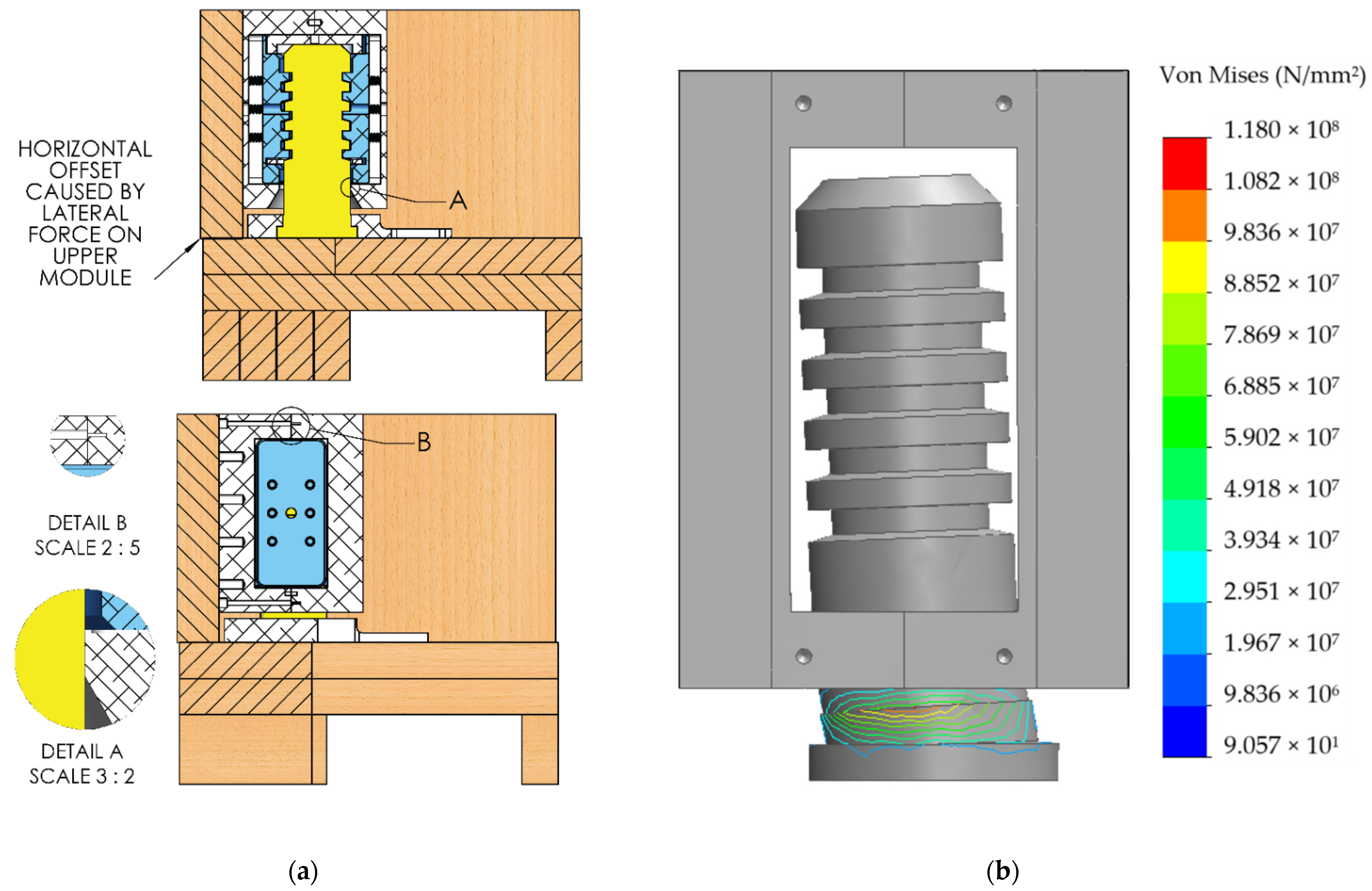
3.4.1. General Analysis
Figure 5a illustrates the displacement induced by the lateral loads that create a separation plane in the NCD. When a lateral force is applied on the FC, a horizontal gap is created between the FC and the CC. This gap creates a loading case which will be referred as shear loading. The two major points of interest in this loading case are the bearing stress at the interface between the shaft and the frame (as can be seen in detail A of
Figure 5a) and the thread pullout at the junction of the two frames (as can be seen in detail B of
Figure 5a). Since the frame is made of aluminium and the bolts are made of steel, with this specific dimensioning, thread pullout is more likely to occur than any type of breakage in the bolts. To oppose the joint separation between the two frames, four ¼-20 bolts were used to link the two frames together (only two are visible in the section plane of
Figure 5a) and four ½-13 bolts were used to link the right frame to the header joist (not visible in the section plane).
Figure 5b presents the deformation of the shaft due to the force exerted at the point of contact with the frame (with a deformation scale of 400:1).
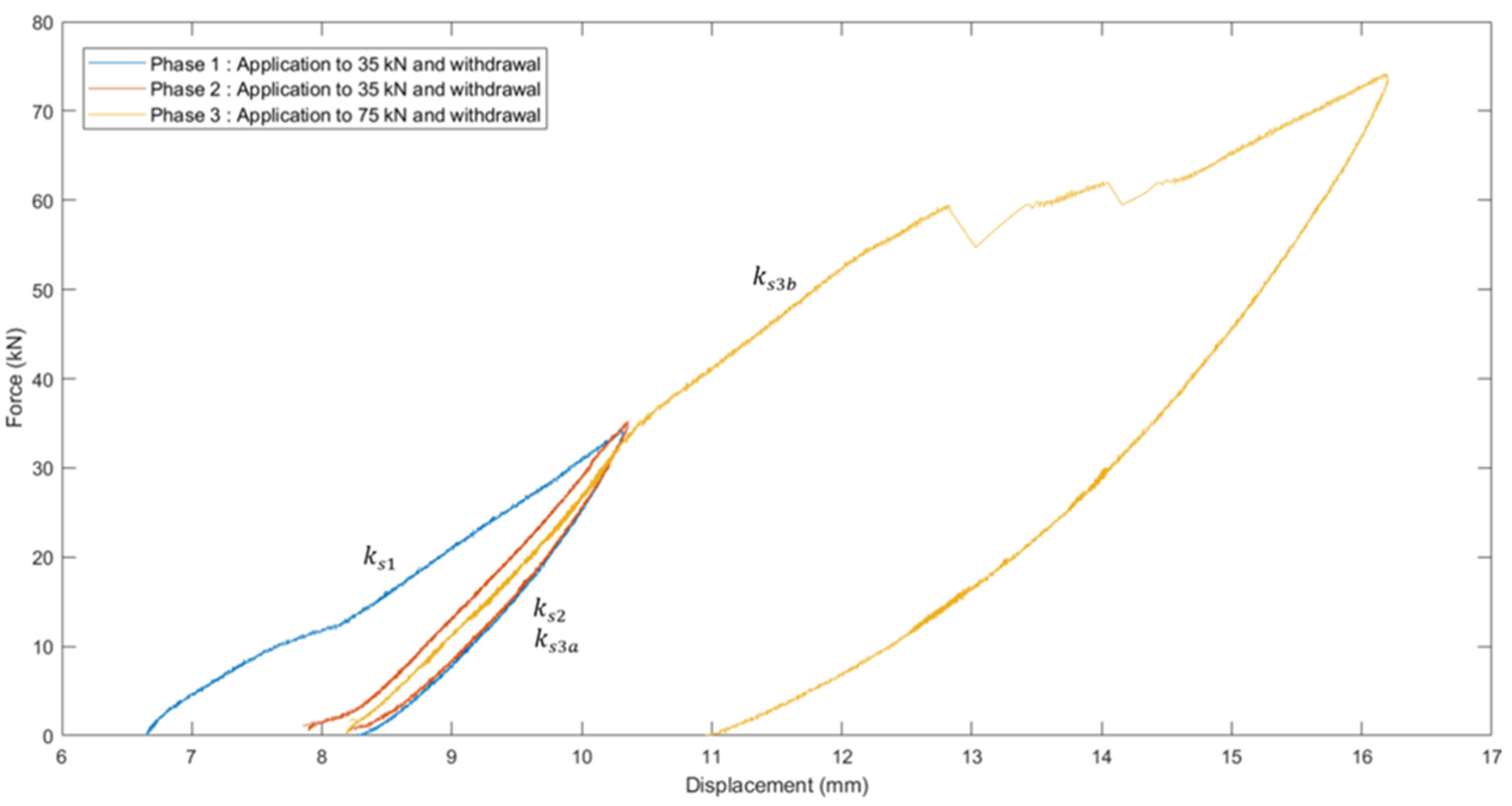
Figure 6 presents the force–displacement graph showing all three phases of force application in shear. The first two phases did not show any major plastic deformation, while the third phase showed a bolt thread pullout at the joining area between the two frames induced by a 59.6 kN force. The observed bolt thread pullout highlights that this specific loading configuration, namely lateral loading originating from inside the module towards the header joist, can lead to a sudden rupture. Prior to the shear testing, finite element analysis showed that a 30 kN lateral force applied at the base of the FC would create a 275 MPa stress at the weakest point of the assembly, which corresponded to the elastic limit of the material. This weakest point is a high-stress-bearing area shown as point A in
Figure 5. After all three phases, no visible permanent deformation was observed at the bearing surface contact, which confirms that bearing stresses can be neglected if the permanent deformation is small enough to have no effects on the functionality and strength of the assembly.
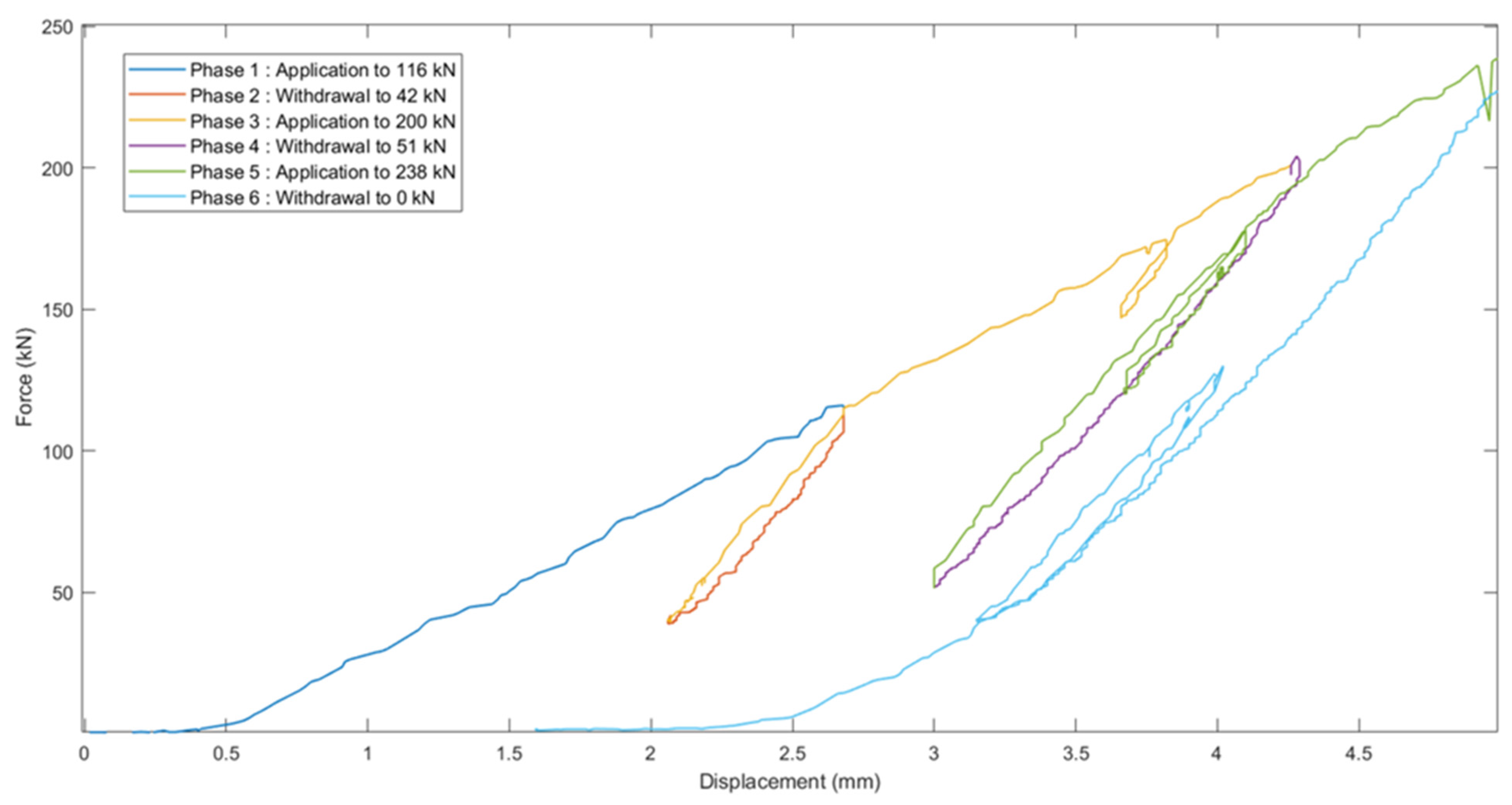
Figure 7 presents the force–displacement graph showing all six phases of force application in tension. No sign of permanent damage was observed throughout this protocol. Moreover, the constant linear behaviour in application phases 1, 3, and 5 shows the absence of permanent deformations. To conclude the tension testing, a tensile force was applied until rupture, which occurred at 300 kN. The shoulder of the shaft presented a pure shear failure mode.
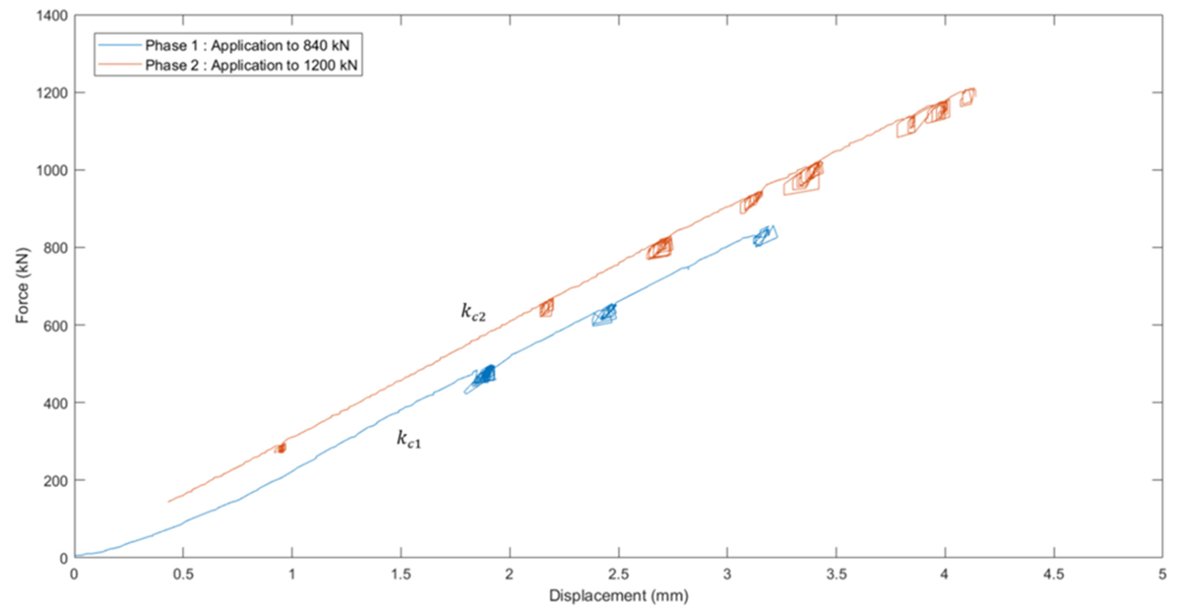
For the compression testing, the results are presented in
Figure 8. The withdrawal data were omitted from the graphs since they were highly noisy and hardly interpretable. This was due to the type of command used in this protocol, which differed from the type of command used for shear testing. In this case, the force application was controlled with a steady speed of application which generated a fixed number of values at every second. The withdrawal of the force followed a unit step command which substantially reduced the number of values obtained. Moreover, the hydraulic system was more stable in pressure increase than in pressure decrease, inducing hysteresis effects caused in part by friction in the seals. The curves obtained from the force application data displayed very similar slopes in both phases of force application. From visual observations, no permanent deformations were noted throughout the compressive testing. FEA calculations showed that no plastic deformation should occur under 1200 kN.
3.4.2. Stiffness Analysis
Since the stiffness of the connector highly depends on the initial position of the internal parts of the assembly and previous force applications, stiffness will be noted as
kij. The I suffix stands for the type of loading, with s for shear, c for compression, and t for tension, and the j suffix refers to the phase of load application (referring to
Figure 6,
Figure 7 and
Figure 8). Stiffness was calculated using the linearly constant parts of the data, and was calculated as follows [
30]:
Figure 6 shows that for shear testing, the first phase (35 kN force application) led to a displacement of 1.605 mm while the second phase (35 kN force reapplication) led to a displacement of 0.310 mm. The stiffness values obtained were
ks1 = 21.81 kN/mm associated with the first force application,
ks2 = 112.90 kN/mm associated with the force reapplication, and a combination of
ks1 and
ks2 in a bi-linear form for the third loading phase, as follows:
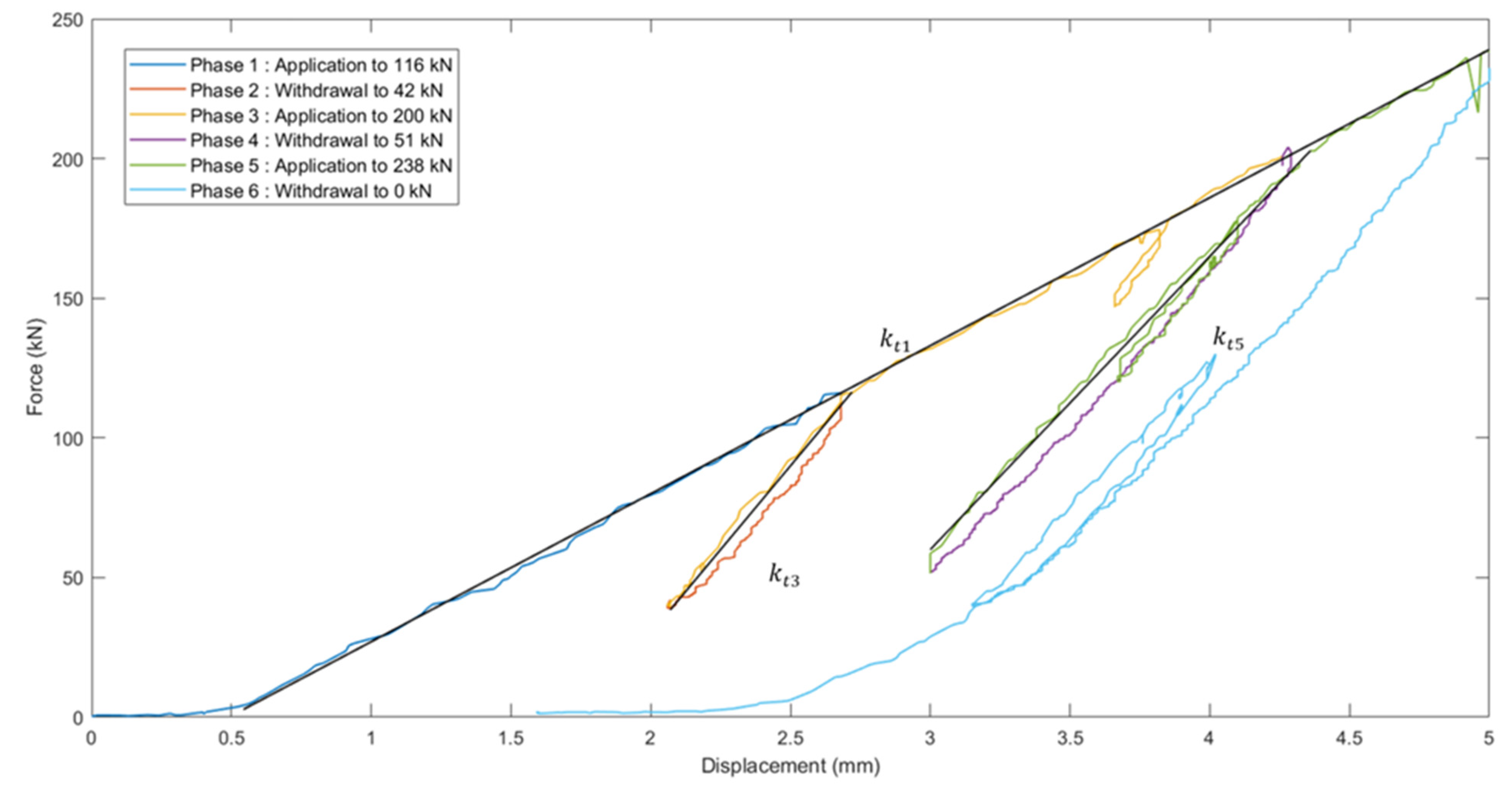
Figure 7 shows that for tension testing, when the force application reached a value for the first time, the associated slope was very similar for phases 1, 3 (the second part of the bi-linear slope), and 5 (the second part of the bi-linear slope). The same phenomenon was observable with the withdrawal phases 2, 4, and 6, which again showed very similar slopes. Phases 3 and 5 showed a combination of a force reapplication and a newly applied force, which led to bi-linear slopes. Indeed, the force reapplication created a hysteresis phenomenon since the internal state of the assembly differed from the initial state. Subsequently, once the reapplied force was equal to the force applied before withdrawal, the slope changed to meet the previous slope. The global force application of 238 kN led to a displacement of 4.43 mm. This led to a stiffness k
t1, valid for the first application of force that ranged between 0 and 238 kN. The reapplication phase 3 increased the force applied from 42 kN to 116 kN, impacting the displacement from 2.07 to 2.71 mm. This led to stiffness k
t3, valid for a force reapplication or withdrawal within this range. The reapplication phase 5 increased the force applied from 53 kN to 206 kN, impacting the displacement from 3.00 to 4.37 mm. This led to stiffness k
t5, valid for a force reapplication or withdrawal within this range. The stiffness values obtained were k
t1 = 53 kN/mm, k
t3 = 116 kN/mm, and k
t5 = 112 kN/mm.
Figure 9 shows the superposition of the approximated curves for stiffness identification for all phases of force application in tension loading.
Figure 8 shows that for compressive testing, the global force application of 800 kN led to a displacement of 2.99 mm, followed by a 1206 kN force associated with a 4.11 mm displacement. The stiffness values obtained with approximated curves (noise cancelling) were k
c1 = 287 kN/mm and k
c2 = 297 kN/mm.
3.4.3. Energy Analysis
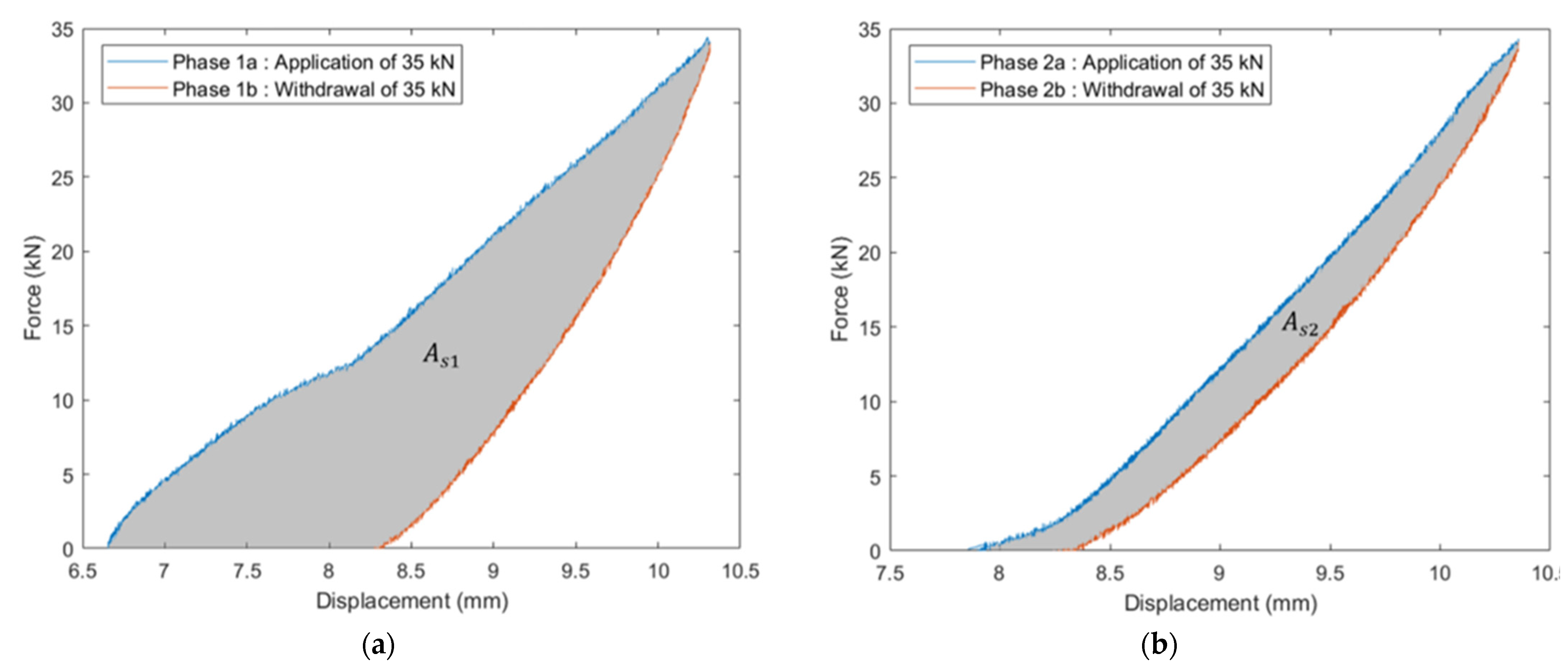
The comparison of phases 1 and 2 of shear testing was used to evaluate the difference in energy absorption between an initial force application and a force reapplication. The energy dissipated during a loading case will differ depending if the previous loading condition had the same direction or not. A repeated force in the same direction will affect the motion of the internal parts, since the gaps that allowed energy dissipation became filled.
Figure 10 shows the integrated area which corresponds to the dissipated energy in the first phase (
Figure 10a) and the second phase (
Figure 10b).
This dissipation of energy would allow, in a structural context, mitigation of the horizontal load transfers, acting like a damping device [
31]. When not subjected to completely reversed loads, subsequent load application will induce a reduction of the dissipated-to-total energy ratio and an increase in the stocked-to-total energy ratio. Since energy absorption is valuable in a structural context, dissipated-to-total energy ratios should be established and compared. Total energy combines the dissipated energy and the elastic energy, and is obtainable with the integration of the force application curve. Hence, the dissipated-to-total energy ratio was 55.5 for the phase 1 in shear and 23.4 for the phase 2 in shear.
The tension loading was analysed exclusively with the total load application and withdrawal of 238 kN. The dissipated energy area was contained between the k_t1 curve and the 6th phase curve presented in
Figure 9. Again, the dissipated-to-total energy ratio was of major interest in this context of initial force application in this specific direction, and showed a values of 53.7, very similar to the initial shear application ratio.
The compression loading led to noisy results regarding the force withdrawal, again cause by the type of command value and the hydraulic instability in the pressure decrease. Hence, an approximated curve was developed, leading to a dissipated-to-total energy ratio of 10.8. This much lower value was expected, however, since critical areas under compressive loading are much larger than in shear or tension, and hence the assembly presented a much higher stiffness and lower damping capacity when subjected to compressive loadings.
Table 4 summarises all the results obtained through testing.
4. Conclusions
In this study, the development of a complete connection solution for modular light-framed wood buildings is detailed. The methodology behind the knowledge gathering comprised a literature review of existing connecting devices as well as factory visits, on-site observations, and interviews with major actors. The combined knowledge led to the development of requirements under two distinct categories of functional and technical design specifications. Design iteration, final design, and testing are also detailed in this article. The main results of this study were as follows.
On-site observations highlighted major efficiency issues. First, the multistep assembly process is inefficient since every module must be permanently linked before pursuing the addition of modules. Additionally, modules have to be delivered at a poor finish level to allow access for connection on-site. Regarding the design phase, it is currently slow because of the absence of standard connecting devices.
The design specifications were detailed as follows. The movement of insertion must be vertical, the locking mechanism must be automated, the module mounting must be easy in the factory process, and the connecting device must help the module alignment. Furthermore, unlocking of the connecting device must be possible and take less than 3 min, the connection must be confirmed via sound or visual proof, the force required for connection must be at least 450 N, and no internal access must be required for connection. Additionally, the connecting device must be located inside the walls and floors to allow for module completion, the connecting device must be usable in the standard range, and the vertical-compressive load paths must be unaffected by the connector. Last, the tensile capacity must be at least 200 kN, while the compressive capacity must be at least 1000 kN and the shear capacity must be at least 40 kN.
The proposed connecting device has two parts (FC and CC), and meets all the design specifications. The connector’s parts are vertically inserted directly into one another on-site and internal parts undergo displacement that triggers the locking mechanism. To ensure easy mounting in the factory, the FC is installed in the floor station simultaneously with the perimeter creation of header joists. Upon installation, the safety bolts are removed and the connector is charged, ready to clamp. The CC is installed in the wall station once the walls are up. For alignment purposes, the shafts can be easily located by the crane operator for module descent, and the shaft top face presents a significant chamfer which tends to centre the shaft in the conic hole located at the bottom of the floor connector, and hence facilitates the alignment process. For disassembly, the pulling out of the four clamps take less than 3 min. For connection confirmation, the second the trigger block is out of the way, the clamps are pushed to the shaft and the contact of these metallic surfaces makes a powerful sound. On assembly day, each worker assigned to a corner will hear the connecting sound and will confirm the connection. To ensure an opposition force at connection, the four clamps, when in the initial position, apply pressure towards the centre because of the compressed springs. This pressure is applied on the trigger block, which creates a friction force that opposes to the movement of the trigger block. To oppose this friction force, 450 N is needed. To maximise internal in-factory finish, no internal access is required and the connector is completely hidden inside the floor system. To ensure a good range of usability, the designed connecting device can be fabricated bigger or smaller depending on the load-bearing capacity needed. Finally, the designed geometry allows for continuous contact between the header joist and the top plate, hence not concentrating the load on the corners and not affecting the vertical load paths.
The economic analysis showed that if the NCD allows modules to be delivered at a 20% higher level of completion (from 60% to 80%), this will corresponds to approximately 14,700$ worth of savings per module.
The testing results showed that for the prescribed capacities, 1000 kN in compression did not induce any plastic deformation and nor did 200 kN in tension, and 40 kN in shear induced permanent deformation at bearing contact but no significant damage and no change in functionality. It also corresponded to approximatively 5/8 of the force that induced thread pullout.
The stiffness analysis showed that the stiffness of the assembly highly differs depending on whether the load is being applied in a direction different to the previous one or if the load is being applied in the same direction as the previous load. The displacement of internal parts led to a different behaviour regarding the amount of energy being stocked or dissipated and changed the rigidity of the assembly.
Further testing is required to complete the characterisation of the NCD. Dynamic loading protocols should allow testing for fatigue and seismic behaviour. Moreover, thermal analysis should be done to ensure that the dew point is located outside the structural members, since wood does not maintain its properties when subjected to a higher humidity level. Future works should also analyse the complex behaviour of a light-framed, modular multistorey building to evaluate whether the design is suitable or not. Following the suggested methodology, the next design step will involve full-scale on-site experiments.


