Article

Calculation of Additional Internal Forces in Post-Tensioned Prestressed Concrete Frame Columns Based on Equivalent Lateral Stiffness

1
School of Civil Engineering, Northeast Forestry University, Harbin 150038, China
2
School of Architecture and Civil Engineering, Qiqihar University, Qiqihar 161006, China
*
Author to whom correspondence should be addressed.
Buildings 2022, 12(5), 644; https://doi.org/10.3390/buildings12050644
Submission received: 9 March 2022 / Revised: 4 May 2022 / Accepted: 8 May 2022 / Published: 12 May 2022
(This article belongs to the Section Building Structures)

Abstract

:
The additional internal forces in vertical members caused by prestressed tendons are typically overlooked in the design of post-tensioned prestressed concrete. A calculation method for additional internal forces in single-story multi-span prestressed concrete frame columns based on equivalent lateral stiffness is proposed in this paper. The slope-deflection equation for the bar element was presented using Timoshenko beam assumptions, taking into account the influence of shear and bending deformations. Subsequently, the concept of equivalent lateral stiffness and calculation equations were proposed. On this basis, the equations of the third shear and third bending moment for single-story multi-span prestressed frame columns were established. Furthermore, applying engineering examples, the method in this study was verified by ABAQUS software and previous methods. The results show that theoretical values and FEA results are in good agreement. Compared to previous methods, the method in this paper is more accurate and widely applicable. In addition, the stretching plan has a significant path effect and time-varying effect on the interlayer distribution of the third moment. It should be considered at the building stage to check the calculation of the frame column.

1. Introduction

Prestressed concrete structures have long been widely used in large-scale, long-span industrial and civil buildings [1,2,3,4,5,6]. In general, prestressed tendons are arranged in horizontal members such as beams and slabs. The stretching of the prestressed tendons during post-tensioned construction results in compressive deformation of the horizontal members. Once this deformation is limited by lateral restraint, such as columns and shear walls, additional internal forces such as shears and bending moments are created in the vertical members. This internal force, in addition to the load and secondary internal force, is referred to as the “third shear” and “third bending moment” [7]. China’s current code [8] does not consider the influence of this additional internal force in the design of prestressed concrete structures with lateral constraints. It is comparable to presuming that the horizontal and vertical members are in a slip connection, which is not supported by facts. Engineering problems caused by additional internal forces are not uncommon. Cracking basement walls and columns in the No.2 building of Binjiang Junyuexiangdi, Changsha, China residential community and basement shear walls in the No.2 building of Yiju Laiyincheng Changsha, China residential community are two typical examples [9]. Therefore, it is of great engineering value to research lateral restraint effects in prestressed concrete structures.
At present, most of the research on the lateral restraint effect focused on discussions of the effective preload of beams. Zhang, D et al. [10] were the first to focus on this issue and derived an equation for the effective preload of beams in the single-story prestressed frame. For multi-story prestressed frames, Jian, B [11] established equations for the effective preload of beams with different construction schemes and gave design suggestions. Subsequently, the effects of beam–column linear stiffness ratio, span number and construction scheme on the effective preload of beams were investigated by Wang, C [12], Zhang, C [13], Cao, X [14], Xia, X [15]. Furthermore, the use of lateral restraint influence coefficients to describe the effect of lateral constraints has been a popular topic [16,17,18,19,20,21]. The concept of the lateral restraint influence coefficient was first proposed by Zheng, W [16]. He established a design method for the cross-section bearing capacity of prestressed beams using the lateral restraint influence coefficient η. Subsequently, an equation for η based on the deformation compatibility method was developed and the conditions for its application were presented [17]. Moreover, Guo, Y [18] and Zhang, Q et al. [19] also obtained an equation for η based on the deformation compatibility method and the matrix displacement method. It was concluded that the deformation compatibility method was more accurate by finite element analysis (FEA). Xiong, X et al. [22], on the other hand, evaluated that using η to express the lateral constraint effect had the characteristics of clear physical meaning and easy calculation. In addition, in practical engineering the effective preload could also be obtained by establishing the overall model by structural design software [23,24].
In recent years, the influence of the lateral restraint effect on column internal force has attracted more and more attention from scholars. Zhang, D et al. [10] argued that the third bending moment was usually in the opposite direction to the bending moment caused by the external load, and that it was advantageous to disregard it for structural design. In contrast, Yan, W et al. [25] and Shen, Q [26] held the opposite view. They believed that the third bending moment should not be ignored, and it may bring potential safety hazards without consideration in design. The equation for the third bending moment applicable to single-story, single-span prestressed frames was then derived. However, the rotation angle at the column end was neglected and the calculation accuracy was poor. The existence of third bending moments was demonstrated by experimental means in an actual project [27]. In addition, it has been found that the stretching plan of prestressing tendons has a significant effect on the third bending moments in multi-story prestressed frames. However, scholars have obtained different influence laws [10,25,26,27,28]. As for the third shear, the equation based on the force method was derived [29]. However, the calculation accuracy is not high due to the oversimplified model. Pan, L [30], on the other hand, established the equation for the third shear by introducing the rotation constraint coefficient and shear distribution coefficient. The proposal that the side column design should take into account the third shear was put forward.
Based on existing research results, it is clear that there are few methods for calculating the additional internal forces, and the accuracy of the calculation needs to be improved. Furthermore, the influence law of the stretching plan on the third bending moment is still highly controversial. Therefore, a calculation method for additional internal forces in single-story multi-span prestressed concrete frame columns is proposed in this paper. The equations for the third bending moment and third shear based on equivalent lateral stiffness were established. Applying engineering examples, the calculation methods were verified by FEA and previous methods. Finally, finite element refinement modeling was applied to analyze the influence law of the stretching plan on the interlayer distribution of the third moment. This study provides fresh ideas to broaden theoretical research on the lateral restraint effect, and the research results can provide some reference for engineering design.

2. Formula Derivation

2.1. Basic Assumptions

The following basic assumptions were made based on the references [25,31].
(1)
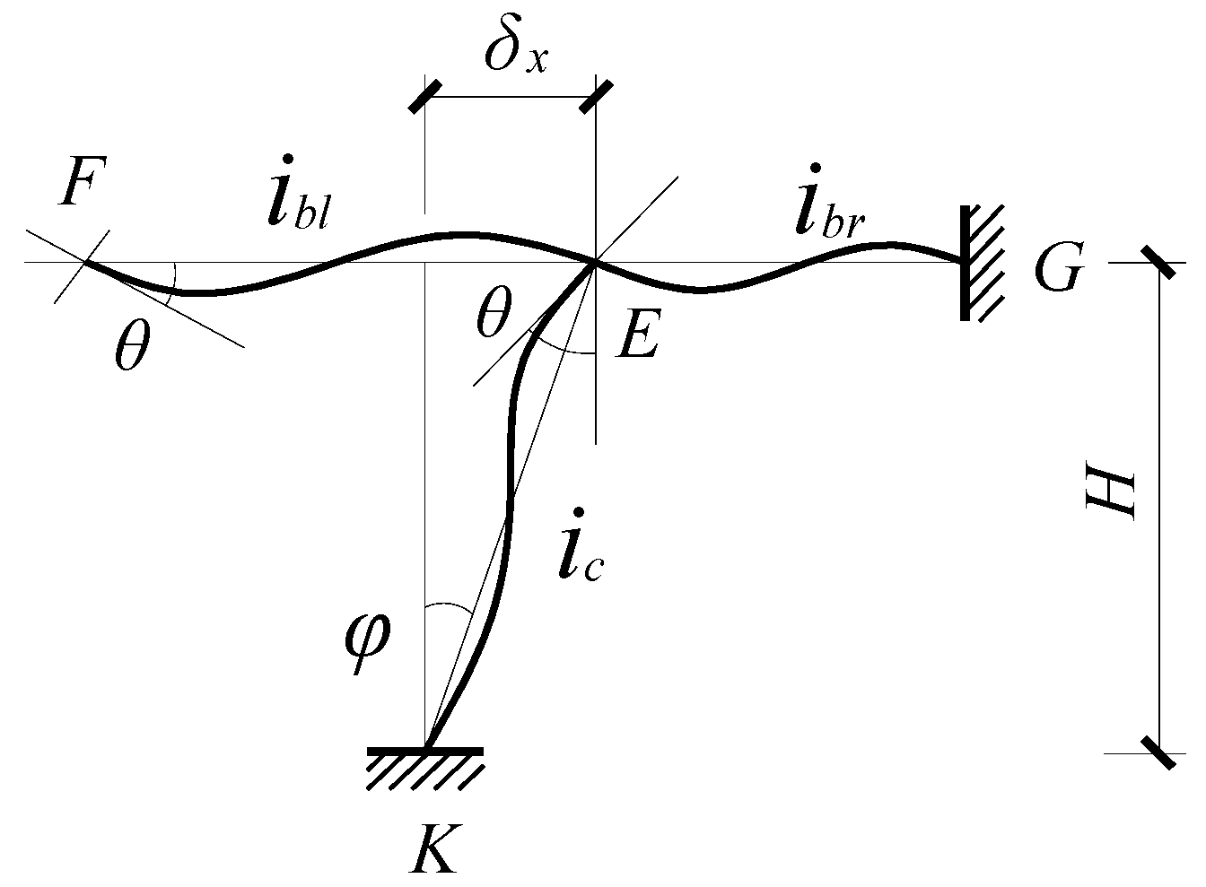
The column section was still flat after being affected by shear deformation, but it no longer remained perpendicular to the axis after deformation. That is, it conformed to the assumption of Timoshenko beams.
(2)
The column-end rotation angle was equal to the beam-end rotation angle, noted as θ.
(3)
Define the effective prestress of prestressed tendons as σpe, the tension control stress as σcon and the total prestress loss as σl. The equivalent load effect at the beam end is Npe = (σconσl)Ap, while excluding the action of the radial equivalent load and the concentrated bending moment.
(4)
The structural forces were in the linear elastic phase, ignoring the plastic deformation caused by shrinkage and creep of the concrete.
(5)
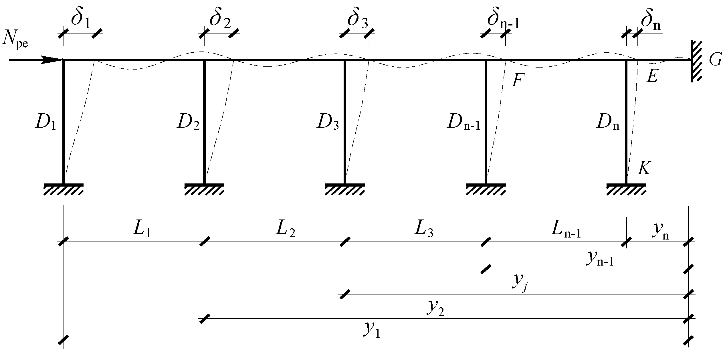
Assuming equal column heights and equal beam sections, the displacement of the column top was linearly related to the distance from the immobility point.

2.2. Equivalent Lateral Stiffness

Generally, the deformation of frame columns under horizontal load includes bending deformation and shear deformation. In frame structures, because of the large shear span ratio of columns, the cross-sectional shear deformation is small and generally negligible [32]. However, in large-span prestressed concrete frame structures, the floor heights are generally not high while column section sizes are large, thus the shear span is relatively small. Shear deformation accounts for a large proportion of the total deformation. Therefore, the lateral stiffness of the column will exhibit a large error if the effect of shear deformation is not considered. In the traditional structural mechanics displacement method, the slope-deflection equation for the bar element only takes account of bending deformation but not shear deformation [33]. Therefore, the slope-deflection equation for the bar element was proposed, where the effect of shear deformations and bending deformation were taken into account in this paper. On this basis, the concept of equivalent lateral stiffness was proposed and its calculation equation was derived.
Plane bar elements are adopted. Figure 1 shows the structural calculation sketch on the side of the deformation immobility point, and bar element EK is shown in Figure 2. For columns without axial pressure action at both ends, the rotation angle of column top is θ, displacement of column top is δn and the chord rotation is φ = δ n H . EI and GA are the flexural stiffness and shear stiffness of the section. The linear stiffness of the beam is i b = E I b l , and the linear stiffness of the column is i c = E I c H . In order to simplify the calculation, θ is only the angle caused by bending deformation, excluding the angle caused by shear deformation. δ is the total displacement caused by bending deformation and shear deformation of the bar element.
Based on reference [25], the curve function yb for bending deformation and ys for shear deformation of the bar element were established. The equilibrium condition of the bending moment in the cross-section is:
E I c y b = M EK + V EK x
The equilibrium condition of the shearing force is:
μ E I c y b ′″ = G A y s
The equilibrium Equations (1) and (2) can be solved as follows:
y b = M EK 2 E I c x 2 V EK 6 E I c x 3 + A x + B
y s = μ V EK G A x + C
where μ is the distribution in homogeneity coefficient of shear stress in the cross-section, and μ = 1.2 is taken for the rectangular cross-section. A, B and C are coefficients to be determined.
According to the boundary conditions of end E, x = 0, yb(0) = 0, ys(0) = 0, yb = θ, then A = θ, B = C = 0.
The solution of the above equation is:
y b = M EK 2 E I c x 2 V EK 6 E I c x 3 + θ x
y s = μ V EK G A x
Equations (5) and (6) are the curve functions of bending deformation and shear deformation of the bar element.
According to the boundary conditions of end K, when x = H, yb(H) = 0, yb(H) + ys(H) = δn, MEK and MKE are expressed as follows:
M EK = 4 + 12 γ 1 + 12 γ i c θ 6 1 + 12 γ i c H δ n
M KE = 2 12 γ 1 + 12 γ i c θ 6 1 + 12 γ i c H δ n
where γ = μ E I c G A H 2 is defined as the ratio of the bending line stiffness to the shear line stiffness of the column, referred to as the line stiffness ratio of bending-shear.
Equations (7) and (8) are slope-deflection equations for the bar element, where the effect of shear deformations and bending deformation were taken into account.
The beam only considers the bending deformation, and its slope-deflection equation is:
M EF = 6 i b l θ
M EG = 4 i br θ
Subsequently, the formula for calculating the shear of column EK, Vn, is expressed as follows:
V n = 12 1 + 12 γ i c H 2 δ n 6 1 + 12 γ i c H θ
Substituting φ = δ n H , the above equation is:
V n = ( 1 θ 2 φ ) 12 i c δ n H 2 ( 1 + 12 γ )
Thus
D n = V n δ n = α n 12 i c H 2 ( 1 + 12 γ )
α n = 1 θ 2 φ
Equation (13) is the equivalent lateral stiffness, where the effect of shear deformations and bending deformation were taken into account.
The value αn is calculated as follows:
Suppose β = M EK M EF + M EG , then
β = 2 i c + 6 γ i c 3 i c φ θ ( 3 i b l + 2 i b r ) ( 1 + 12 γ )
Additionally
θ φ = 3 i c 2 i c + 6 γ i c β ( 3 i b l + 2 i b r ) ( 1 + 12 γ )
So αn can be expressed as follows:
α n = 0.5 i c + 6 γ i c β ( 3 i b l + 2 i b r ) ( 1 + 12 γ ) 2 i c + 6 γ i c β ( 3 i b l + 2 i b r ) ( 1 + 12 γ )
where β is the ratio of the bending moment borne by the column to the sum of the bending moment of the beam on both sides. Since the direction of the bending moment of the beam and column are opposite, β is negative. To simplify the calculation, according to engineering experience, β = 1 3 is obtained by reference [34]. Let k ¯ = i b l + i b r i c , for the same span, the correction factor of the linear stiffness ratio of beam-column is λ.
Then αn can be simplified as follows:
α n = 0.5 + 6 γ + λ k ¯ ( 1 + 12 γ ) 2 + 6 γ + λ k ¯ ( 1 + 12 γ )
Equation (18) is the correction factor for the linear stiffness ratio of beams and columns to correct the lateral stiffness resistance, where λ = 0.78 when the number of spans is odd, λ = 0.83 when the number of spans is even, and λ = 1 for other columns αj [34].
It should be noted that for single-story and single-span prestressed frame structures, only the rotational restraint of the beam on one side of the column needs to be considered, then ibl = 0, k ¯ = i b i c . Equation (17) can be simplified as follows:
α 1 = 0.5 + 6 γ + 0.67 k ¯ ( 1 + 12 γ ) 2 + 6 γ + 0.67 k ¯ ( 1 + 12 γ )
Once the correction factor of lateral stiffness is found, the equivalent lateral stiffness of the frame column can be solved by using Equation (13).

2.3. Third Shear

According to the deformation compatibility principle in structural mechanics, the column top displacement of the side column is the sum of the axial compression displacements of all span beams. δ1 is expressed as follows:
δ 1 = j = 1 n Δ b j
According to the assumption (5), the sum of the axial compression displacement of all spans caused by stretching of prestressed steel tendons is δbj,as follows:
δ b j = N b j l j E A
The position of the immovable point is determined according to reference [4]. As shown in Figure 1, the distance from the immovable point to the side column is y1 and let the distance from the n-th column to the immovable point be yn, then y n = y 1 j = 1 n 1 L j , as follows:
y n = L 1 j = 2 k D j + L 2 j = 3 k D j + + L k 1 D k j = 1 n D j j = 1 n 1 L j
The preload of the beam is reduced for each span, which is represented by Nbj (j = 1, 2…n), as shown in Figure 3, as follows:
N b j = N pe j = 1 n V j
Subsequently,
δ 1 = ( N pe V 1 ) L 1 + + ( N pe - j = 1 n V j ) y n EA
Equation (24) can be simplified as:
δ 1 = N pe y 1 j = 1 n V j ( m = j n 1 L m + y n ) EA
Based on assumption (5), it is known that the displacement of the column top is linearly related to the distance from the immobile point. As a result of δ 1 = V 1 D 1 , Vj can be calculated by using:
V j = δ j D j = y j y 1 D j D 1 V 1
Vj is expressed as follows:
δ 1 = N pe y 1 j = 1 n y j y 1 D j D 1 V 1 ( m = j n 1 L m + y n ) EA
The shear of column j can be calculated by using:
V j = N pe y j D j EA + j = 1 n D j y j y 1 ( m = j n 1 L m + y n )
Equation (28) is the formula for calculating the third shear of column j for single-story and multi-span prestressed frame structures.

2.4. Third Moment

The third moment of the column bottom section is:
M j b = V j η j H
where ηj is the height ratio of the point of changing curve, which can be obtained by reference [34].
Substituting Vj into Equation (29), the third moment of the bottom section of the column j can be calculated by using:
M j b = N pe y j D j η j H EA + j = 1 n D j y j y 1 ( m = j n 1 L m + y n )
Equation (30) is the third bending moment calculation formula for the bottom section of column j for single-story and multi-span prestressed frame structures. Replace ηj with (1 − ηj) to get the third bending moment of the top section of column j, noted as M j t . From Equations (28) and (30), it can be seen that the third shear and third bending moment are related to the equivalent lateral stiffness of the column, the precompression of the beam and the number of spans. The side column suffers the largest additional internal force.

3. Method Validation

3.1. Finite Element Model Verification

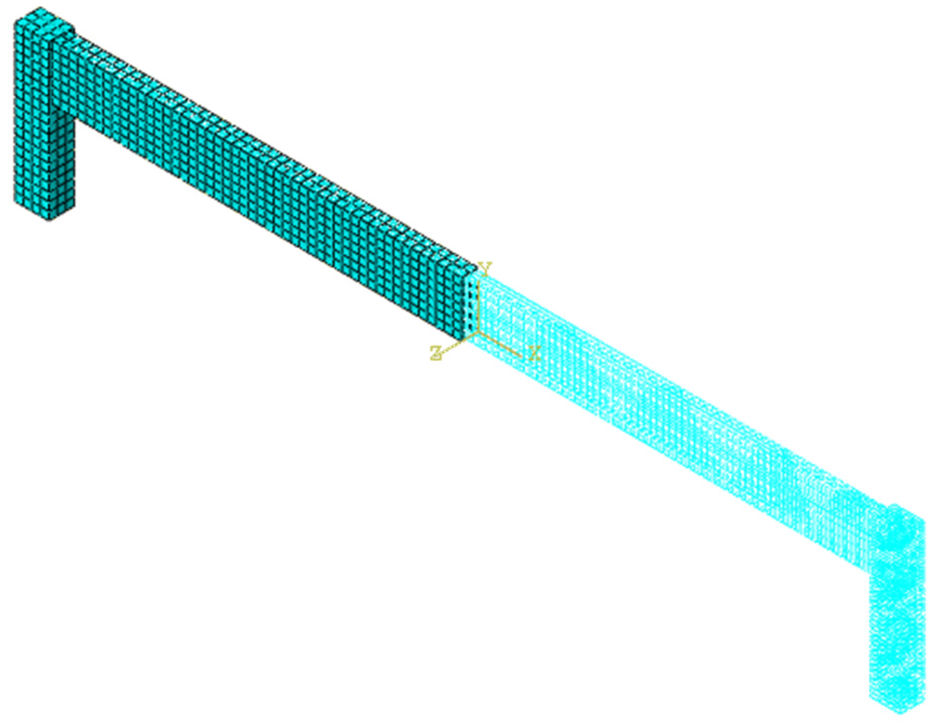
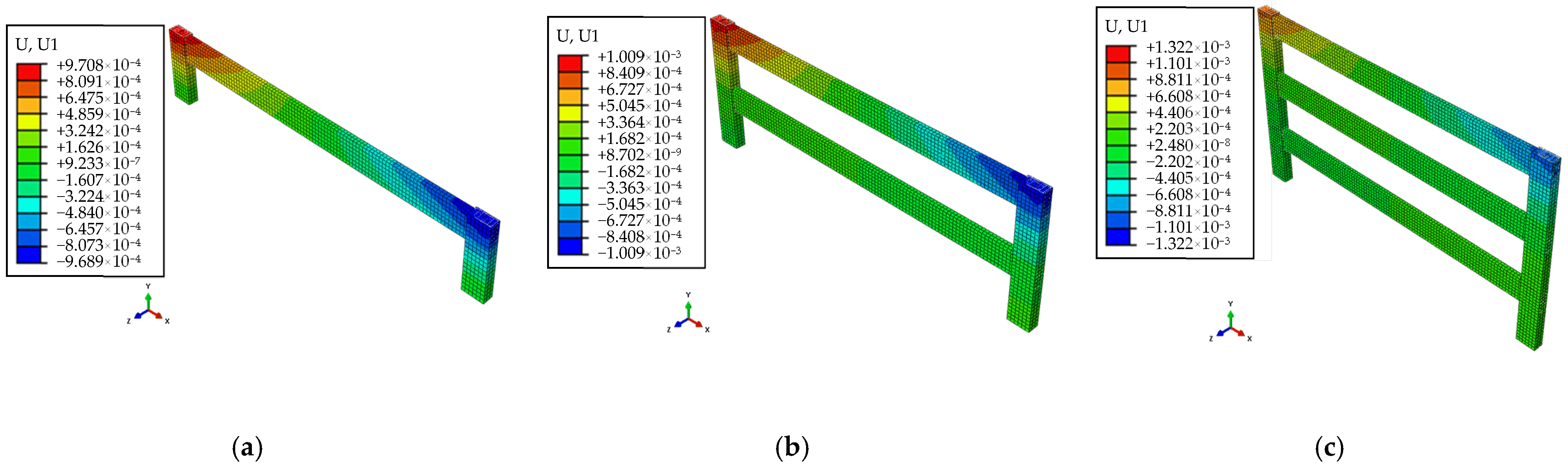
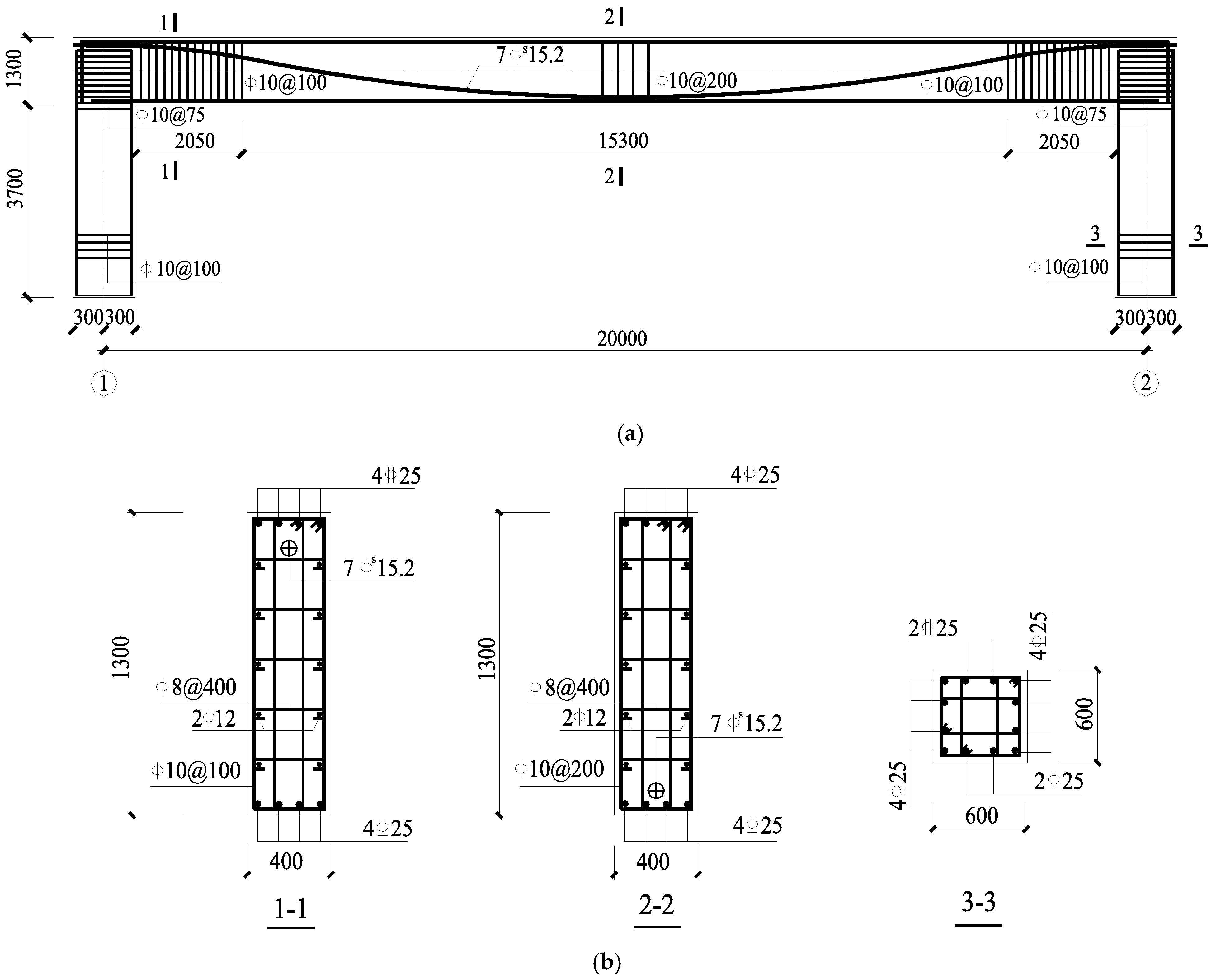
3.1.1. Establishment of Finite Element Model

A project example was modeled and analyzed to verify the accuracy of the calculation method in this paper with ABAQUS. As shown in Figure 4a,b, a single-story and single-span prestressed concrete frame structure with a span of 20 m and a floor height of 5 m is used for the project. Both beams and columns are made of C40 concrete. The beam cross-sectional size is b × h = 400 mm × 1300 mm, and column cross-sectional size is b × h = 600 mm × 600 mm. The prestressed beam is equipped with unbonded prestressing tendons 7 ϕ s 15.2. The prestressing tendons are all made of high-quality steel strands with low relaxation of 1860 grade. The tensioning control stress is 0.75 fptk, prestress loss is 20%, and the effective prestress is Npe = 1416 kN. Prestressing tendons are arranged in a double parabolic shape, tensioned at both ends with a sagittal height of 150 mm at the midspan and 150 mm at the beam-end. A total of 10 models are analyzed by varying the column section height, the effective preload value at the beam end and increasing the number of spans. Parameters of finite element models are shown in Table 1.
In the modeling process, the concrete was simulated using an eight-node linear reduced-integral 3D solid unit C3D8R, and all steel bars were simulated by truss unit T3D2 [35,36]. An elastic perfectly plastic model was used for ordinary steel bars and prestressed steel strands. The concrete damage plasticity (CDP) model for concrete in ABAQUS was used [37,38,39,40]. The constitutive was adopted according to the Chinese Standard for Design of Concrete Structures (GB 50010-2010) [8]. In defining the interaction between the steel bar and concrete, the separate modelling was used to couple the reinforcement to the concrete with degrees of freedom in the ‘Embed’ method, and the connection was made by means of ‘Tie’ constraints on the frame beams and columns. [41,42,43]. A fixed boundary condition (U1 = U2 = U3 = UR1 = UR2 = UR3 = 0) was applied to the bottom surface of the column as an initial condition. The cooling method was used to apply prestress to the truss unit T3D2 [44,45]. To improve analysis efficiency, for the multi-span prestressed frame structures YKJ8, YKJ9 and YKJ10, axisymmetric models were created by imposing symmetric boundary conditions on the split boundary of the symmetry axis [46,47]. The finite element model of YKJ1 is shown in Figure 5. Details of the material parameter values for the finite element model are shown in Table 2.

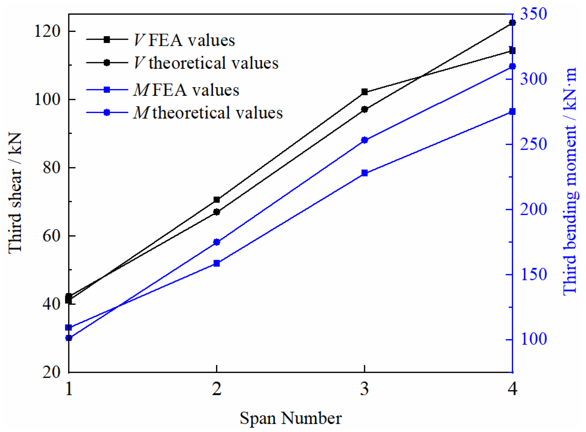
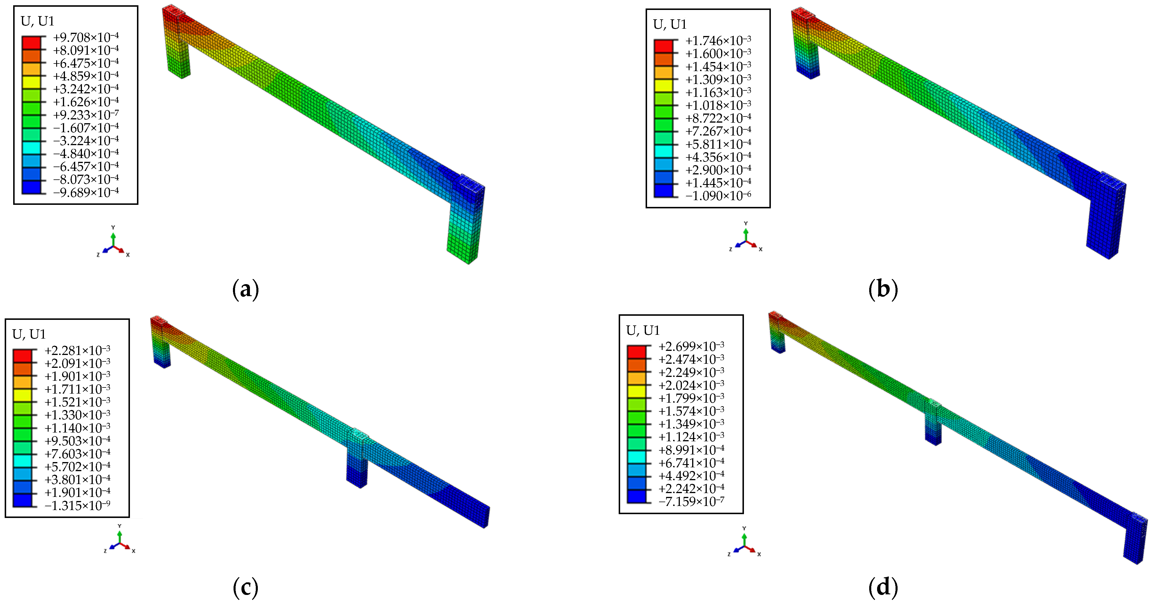
3.1.2. Results and Discussion

The third shear and the third bending moment of side columns obtained by FEA and the method of this paper are listed in Table 3. The calculation results of the method of this paper are in good agreement with the finite element analysis values. The results show that the relative error of the third shear is 0.36% to 7.18%, and the relative error of the third bending moment is 0.66% to 12.52%. The calculation accuracy meets engineering requirements, which verifies the reliability of the calculation method of this paper. Except for YKJ4, the calculation accuracy of the third shear obtained by the method of this paper is generally higher than that of the third bending moment. The reason for this is that the standard height ratio of the point of the changing curve is restricted to the situation of uniform load [34], which differs from the case of horizontal load to the column top in this study. The calculated value of the method in this paper is consistently larger than the finite element analysis value, which is because of the simplified rod model used in the derivation of the formula in this paper. The influence of plastic deformation caused by compression and creep of concrete is ignored.
Figure 6 shows the effect of equivalent lateral stiffness on the third shear and third bending moment. The third shear and the third bending moment rise as the equivalent lateral stiffness of the frame column increases. This is because the lateral restraint capacity of the frame column on the prestressed beam gradually enhances with the increase in lateral stiffness of the frame column. The distribution ratio of the axial prestressing force involved in the beam becomes increased, and thus the additional internal force increases. As a result, it is advantageous to improve the structure’s flexibility in order to lessen the effect of additional internal forces while fulfilling the bearing capacity and normal use requirements during design.
According to Equation (20), the capital level displacement of the side column is the sum of the axial compression deformation of each span caused by the stretching of prestressed steel tendons. As shown in Figure 7, the displacement values are 0.971 mm, 1.746 mm, 2.281 mm and 2.699 mm for single span, double-span, three-span and four span frames, respectively. It can be seen that, as the number of spans increases, the capital level displacement increases. As a result, the axial preload force allocated to the column by the beam increases due to the third shear force, which in turn causes an increase in the third bending moment, as shown in Figure 8. In actual engineering, for continuous multi-span prestressed structures, it is advisable to set post-cast zones and carry out segmental tensioning of prestressing tendons or take other measures during construction to reduce the influence of span number, especially for side columns. In addition, the values of the third shear and the third bending moment of the side columns increase with the increase in the effective prestressing force value and conform to a linear relationship, which is consistent with Equations (28) and (30).

3.2. Comparison with Previous Methods
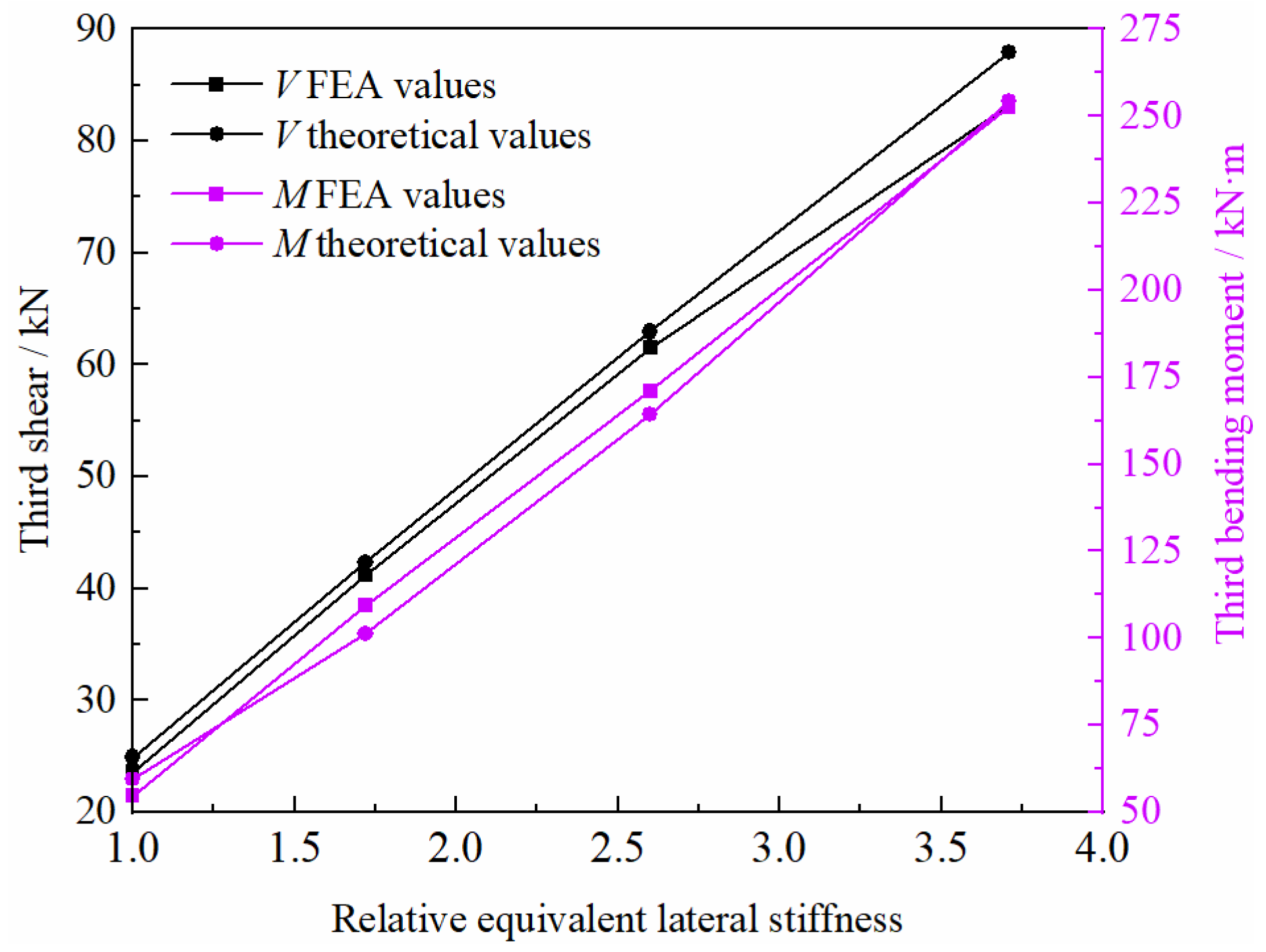
3.2.1. Third Shear

Figure 9 shows the third shear relative errors of the YKJ1-YKJ10 side columns as determined using the method of FEA, references [25,30] and our study. It should be noted that reference [25] only gives the calculation method for single-story and single-span structures, so only the third shears of YKJ1 to YKJ7 are shown in Figure 9. Table 4 shows the comparison of the average relative error of the third shear.
The calculation accuracy of the third shear achieved by the method proposed in this paper is much greater than that of previous methods. The third shears obtained using the method of [25] are all larger. The error range is 10.44% to 83.88%, with an average error of 31.06% and a dispersion coefficient of 0.86. It implies that the third shear is significantly exaggerated, with a substantial error. Especially for the YKJ4 specimen with relatively large lateral stiffness resistance, the error is the largest. The relative errors of the third shear calculated using the method of [30] varied from 0.95% to 37.56%, with an average error of 11.52% and a dispersion coefficient of 1.06. This indicates that the calculation accuracy of this method is relatively high, but the dispersion of the calculation results for different specimens is large. The relative error of the third shear obtained by the calculation method in this paper is 0.36% to 7.18%, with an average error of 3.37% and a dispersion coefficient of 0.62. It shows that the method in this paper has a small error, little dispersion, and the highest calculation accuracy.

3.2.2. Third Bending Moment

Figure 10 shows the relative third bending moment errors of the YKJ1-YKJ7 side columns as determined using the method of FEA, reference [25] and our study. The average relative errors calculated by reference [25] and our methods are shown in Table 5. It can be seen that the accuracy of calculating by this paper’s method is significantly higher than that of reference [25]. The third bending moment in reference [25] is 2.45% to 47.62% larger than FEA values, with the largest error for YKJ5. The average relative error is 20.3% and the dispersion coefficient is 0.81. The relative error by this paper’s method ranges from 0.66% to 9.23%, with an average value of 6.41% and a dispersion coefficient of 0.46. It is clear that both the calculation error and dispersion of the method in this paper are small, which fully demonstrates that the equation in this paper can accurately evaluate the third bending moment.

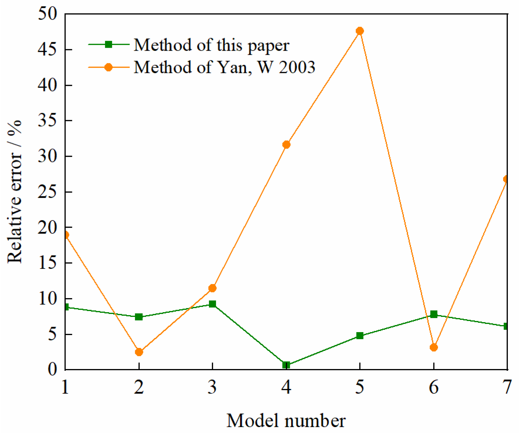
3.2.3. Accuracy Analysis

Reference [25] assumed consolidation at the column end and did not consider the effect of the rotation angle at the column end. At the same time, the solution of lateral stiffness resistance only considered the influence of bending deformation of the column, which led to its large calculated value. Therefore, the lateral restraint capacity of the column was seriously overestimated, resulting in large errors in the calculated values of additional internal forces. The column end restraint and shear distribution were considered by adopting the rotational constraint coefficient and the shear distribution coefficient in reference [30]. However, the lateral stiffness did not take into account the effect of shear deformation of the column section. Poor calculation accuracy for structures with high lateral stiffness indicated that it is not universally applicable. In contrast, the equivalent lateral stiffness proposed in this paper could accurately assess the lateral restraint resistance of columns, by considering both shear and bending deformation effects. This stiffness could reasonably determine the distribution ratio of the frame column involved in the axial preload of the beam and ensure the accuracy of calculations of the additional internal force value. Therefore, compared with the existing calculation methods, the method in this paper has higher accuracy. Equivalent lateral stiffness is a key factor in determining the accuracy of additional internal force calculations.

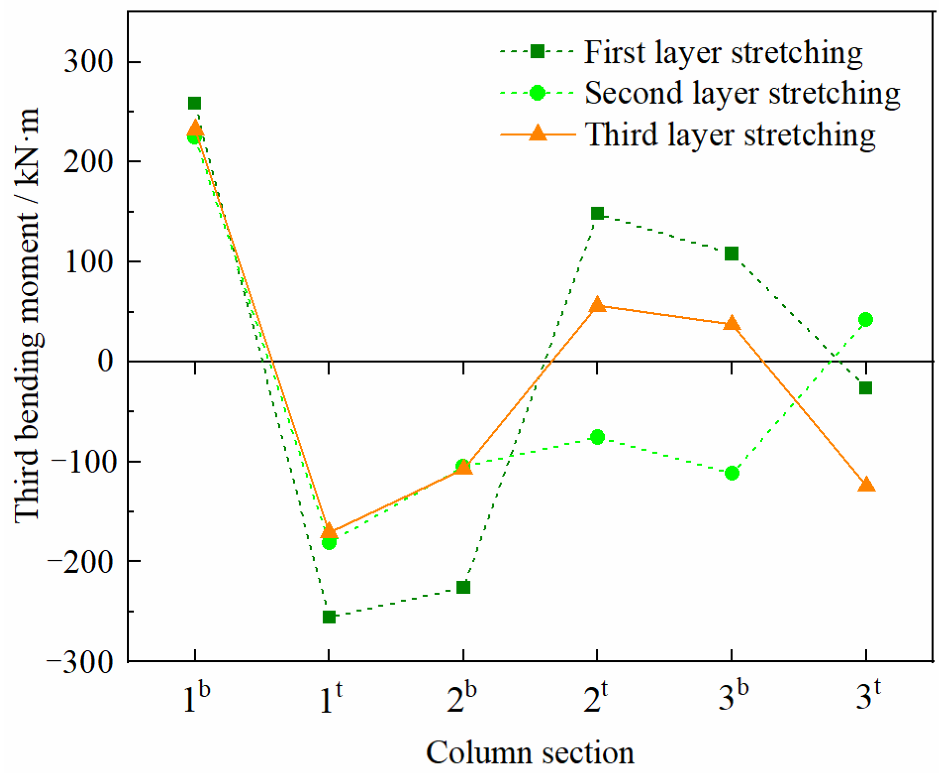
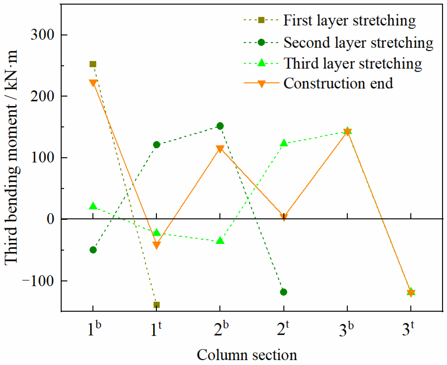
4. Influence of Tensioning Order during the Construction Phase

For multi-story prestressed frames, the current design method employs the “integral casting, one-time tensioning” structural model in overall structural analysis [48]. It ignores the effect of the stretching plan of prestressed tendons on structural internal forces, resulting in the difference between the design value and the actual value, particularly for the bending moment [49]. However, it is very difficult to establish a theoretical formulation considering the dynamic changes in the construction process. Therefore, in this paper, finite element simulations of the construction process with different stretching plans for multi-story prestressed frames were carried out. We hope to find out the influence law of stretching plans on the interlayer distribution of the third bending moment.
A finite element model of a single-span three-story prestressed concrete frame was built using the fundamental characteristics of the YKJ2 specimen. The impacts of the several-layer and layer-by-layer stretching plan on the third bending moment were investigated. Figure 11 and Figure 12 show X-direction displacement cloud images of the several-layer stretching plan and layer-by-layer stretching plan. The distribution of the third bending moment of the side columns between layers for the several-layer method and the layer-by-layer method are shown in Figure 13 and Figure 14. It should be noted that the third moment value of the column after tensioning of the third layer of prestressed tendons in Figure 13 is also the final value calculated by the current design method.
The tensioning scheme has a path effect on the interlaminar distribution of the third bending moment between layers. Compared to the total bending moment under external loads in reference [25], the distribution of the final value of the third bending moment in the layer-by-layer method is staggered with it, with odd layers mutually abating favorably and even layers superimposing unfavorably. The layer-by-layer method is opposite to the direction of the external load moment, and each layer of the column moment can be mutually reduced. For the same structure, different construction schemes correspond to different structural response histories and final responses of the third bending moment.
Tensioning scheme has a time-varying effect on the distribution of the third bending moment between layers [50]. The bottom and top of the column at the bottom layer of the construction of the several-layer method are the control section. The third bending moment at the top of the bottom column of the first layer beam after prestressing tendon tensioning is the largest, which is 1.5 times the final value and taken as the design control value. The control sections of layer-by-layer method construction are the bottom and top layer column bottom, the middle layer column bottom, and the column top. After stretching the prestressing tendons of the third layer beam, the third bending moment at the bottom section of the top layer column is the largest, which is 3.8 times the final value calculated by the current design method and is the design control value. Therefore, the tensioning construction scheme is different, the time and size of the design control value is different, and the control section position of the third bending moment is different.
It is advisable to use the third bending moment design control value of each story column for crack width and bearing capacity verification during the construction stage. Generally, prestressed concrete frame structures have few layers. The vertical loads often play a controlling role in the service phase, and the design is usually on the safe side without considering the effect of the third bending moment. However, during the construction stage, the prestressed beam formwork and supports are not removed, and the vertical load effect is very small. At this time, if the third bending moment value is large, it may lead to shear and bending failure at the column end. Therefore, it is recommended to check the calculation for the construction stage.

5. Conclusions

To determine the additional internal forces of columns caused by prestressed tendons more accurately, a calculation method based on equivalent lateral stiffness was proposed in the paper. Shear and bending deformation were considered in the equivalent lateral stiffness of the column. The deformation compatibility and force equilibrium conditions were established according to the equivalent lateral stiffness, and equations for the third shear and third bending moment were proposed based on these conditions. The proposed method was verified by FEA and compared with previous methods to demonstrate its superior performance. In addition, the effect of the stretching plan on the interlayer distribution of the third bending moment was analyzed by a single-span three-story finite element model. The following conclusions can be drawn:
  • The slope-deflection equation for the bar element was derived considering the effect of shear deformations and bending deformation. On this basis, the equation for the equivalent lateral stiffness of frame columns was derived. The equation could effectively evaluate the lateral restraint capacity of the column and had good applicability.
  • The third shear and third bending moment values calculated by the proposed method were in good agreement with FEA results. The average relative error of the third shear is 3.37%, and that of the third moment is 6.41%. Compared to the existing methods, the calculation method in this paper had higher calculation accuracy.
  • The proposed method can be directly applied to solve the additional internal forces in columns for post-tensioned single-story multi-span prestressed concrete frames with prestressed tendons stretched at beam both ends. The accuracy of the calculation meets engineering requirements. Considering the effect of equivalent lateral stiffness, span number and preload value, the method has more reliability and applicability.
  • The stretching plan has a significant path effect and time-varying effect on the interlayer distribution of the third moment. It is advisable to use the third bending moment design control value of each story column for crack width and bearing capacity verification during the construction stage.

Author Contributions

Conceptualization, D.C. and L.W.; methodology, L.W. and D.C.; software, E.Q. and L.W.; validation, D.Z. and C.L.; formal analysis, D.C.; investigation, L.W.; resources, D.C.; data curation, E.Q.; writing—original draft preparation, L.W. and D.C.; writing—review and editing, L.W. and D.C.; visualization, L.W.; supervision, D.C.; project administration, D.Z. and C.L.; funding acquisition, D.C. All authors have read and agreed to the published version of the manuscript.

Funding

This research is financially supported by Basic Scientific Research Business Projects of Heilongjiang Provincial Education Department (135309358); Central Universities Basic Research Business Fund for Innovative Teams and Major Projects Training Funds Project (2572016EBC1). National Natural Science Foundation of China (51908108).

Institutional Review Board Statement

Not applicable.

Informed Consent Statement

Not applicable.

Data Availability Statement

The data presented in this study are available on request from the corresponding author.

Conflicts of Interest

The authors declare no conflict of interest.

References

  1. Xiong, X.; Yao, G. Research progress and design theory of modern prestressed concrete structure. Build. Struct. 2018, 48, 1–4. [Google Scholar]
  2. Gao, F.; Xiong, X.; Yuan, H.; Zhang, J.; Guo, J. Structural design of bonded post-tensioned prestressed steel reinforced concrete frame beams with large span. Build. Struct. 2018, 48, 16–20. [Google Scholar]
  3. Kurosawa, R.; Sakata, H.; Qu, Z.; Suyama, T. Precast prestressed concrete frames for seismically retrofitting existing RC frames. Eng. Struct. 2019, 184, 345–354. [Google Scholar] [CrossRef]
  4. Abdel-Jaber, H.; Glisic, B. Monitoring of prestressing forces in prestressed concrete structures-An overview. Struct. Control. Health Monit. 2019, 26, e2374. [Google Scholar] [CrossRef] [Green Version]
  5. Zhang, S.; Yang, M.; Qin, H.; Wang, Y. Design of the prestressed frame beam of a large-span gymnasium. Build. Struct. 2021, 51, 1260–1263. [Google Scholar]
  6. Zhang, Y.; Gong, Z.; Lv, W.; Wu, Y.; Luo, Y. Structure design of large span concrete floor of a high school complex building in Wuhan. Build. Struct. 2021, 51, 1255–1259. [Google Scholar]
  7. Cheng, D.; Xue, Z. Pre-Stressed Concrete Structures; China Metrology Press: Beijing, China, 2010; pp. 166–167. [Google Scholar]
  8. GB 50010-2010; Chinese Standard for Design of Concrete Structures. Architecture and Building Press: Beijing, China, 2010.
  9. Chen, D.; Lin, Y. Analysis of lateral restraint effects for super-long one-story prestressed slab-column structure. Ind. Constr. 2012, 42, 58–61. [Google Scholar]
  10. Zhang, D.; Lv, Z. Effect of lateral restraint on the pressure of prestressed concrete frames. Build. Struct. 2001, 31, 51–52. [Google Scholar]
  11. Jian, B.; Wu, C. Effect of lateral restraint on beam axial forces in multi-story prestressed concrete frames. Build. Struct. 2004, 34, 25–27. [Google Scholar]
  12. Wang, C.; Meng, S. Analysis of lateral restraints of prestressed concrete frame structures. Ind. Canstructian 2007, 37, 47–50. [Google Scholar]
  13. Zhang, C. Research on the Design Method of PC Structure under Hyperstatic Restraint. Master’s Thesis, Tongji University, Shanghai, China, 2007. [Google Scholar]
  14. Cao, X. Theoretical analysis of effect of lateral restraints on RC frame beams strengthened with external prestressing tendon. Archit. Technol. 2009, 40, 162–165. [Google Scholar]
  15. Xia, X.; Peng, Z.; Lu, Z. Finite element analysis on construction of post-tensioned concrete frame. Concrete 2011, 11, 132–134. [Google Scholar]
  16. Zheng, W.; Zhou, W. Methods for analyzing lateral restraint of prestressed concrete structures. J. Harbin Univ. Civ. Eng. Archit. 2001, 34, 12–16. [Google Scholar]
  17. Cheng, D. Theoretical analysis on the effect of vertical bracing on the value of prestress of continuous beams. J. Northeast. For. Univ. 2005, 33, 71–72. [Google Scholar]
  18. Guo, Y. Analysis of the Influence of Lateral Restraint on Prestressed Concrete Statically Indeterminate Structures. Master’s Thesis, Harbin Engineering University, Harbin, China, 2014. [Google Scholar]
  19. Zhang, Q.; Wang, G.; Ye, L. Theoretical analysis of lateral restraint of prestressed super-stationary structures. Low Temp. Archit. Technol. 2014, 36, 58–60. [Google Scholar]
  20. Fang, S.T.; Zhang, Y.; Gao, Y. The Influence of Lateral Confinement in Prestressed Concrete Structure under the Effect of Pre-Applied Force. Adv. Mater. Res. 2012, 479–481, 1687–1690. [Google Scholar] [CrossRef]
  21. Lin, Y. Analysis and Research on the Influence of Lateral Restraint to Post-Tensioning Prestressed Concrete Structure. Master’s Thesis, Hunan University, Changsha, China, 2011. [Google Scholar]
  22. Xiong, X.; Xiang, R.; Wang, J. Prestress design of super-long concrete structure. Build. Struct. 2018, 48, 5–8. [Google Scholar]
  23. Mao, C. A Design Example of Post-Tensioned Bonded Prestressed Concrete Frame Structures. Constr. Des. Proj. 2019, 5, 27–28. [Google Scholar]
  24. Xu, Z. Study on Prestressing Impact to Internal Force of Frame Structure. Master’s Thesis, Lanzhou Jiaotong University, Lanzhou, China, 2015. [Google Scholar]
  25. Yan, W.; Ma, L. The effect on the column moment considering compress of prestressed concrete beam. J. Chongqing Univ. (Nat. Sci. Ed.) 2003, 26, 117–119. [Google Scholar]
  26. Chen, Q. Design and Analysis of the Long-Span Prestressed Concrete Frame Structure. Master’s Thesis, Hefei University of Technology, Hefei, China, 2014. [Google Scholar]
  27. Hu, C.; Fu, L.; Guo, Y. Analysis a monitoring of the influence of the column’s force on the prestressed frame beam tensioning. J. Xi’an Univ. Archit. Technol. (Nat. Sci. Ed.) 2012, 44, 609–613, 626. [Google Scholar]
  28. Chen, C. Research of Lateral Restraint Influence on Pre-Stressed Effect of Concrete Frame Beam. Master’s Thesis, Hefei University of Technology, Hefei, China, 2008. [Google Scholar]
  29. Deng, T.; Liu, P.; Xiao, J.; Wang, C.Z. Calculation for secondary interior force in statically indeterminate prestressed concrete structure considering the effect of lateral restraints. J. Jiangxi Univ. Sci. Technol. 2014, 35, 22–28. [Google Scholar]
  30. Pan, L. Calculation Analysis for Prestress Loss due to Structural Constraint in Post-Tensioned Concrete Structures. Build. Sci. 2004, 20, 22–25. [Google Scholar]
  31. Tong, G.; Weng, Y. The elastic buckling of frame columns considering the effect of the shear deformations. Eng. Mech. 2008, 25, 171–178. [Google Scholar]
  32. Qian, J.; Zhao, Z.; Ji, X.; Ye, L. Structural Design of High-Rise Building, 3rd ed.; China Architecture & Building Press: Beijing, China, 2021; p. 140. [Google Scholar]
  33. Qu, L.; Yang, Z.; Wang, H. Structural Mechanics, 3rd ed.; China Electric Power Press: Beijing, China, 2021; p. 242. [Google Scholar]
  34. Liang, X.; Shi, Q. Concrete Structure Design, 4th ed.; China Architecture & Building Press: Beijing, China, 2019; pp. 223–225, 301–307. [Google Scholar]
  35. Yuan, H.A.; Yt, B.; Wy, A.; Yun, Z.A.; Lu, D.A. Numerical investigation on compressive arch action of prestressed concrete beam-column assemblies against progressive collapse. J. Build. Eng. 2021, 44, 102991. [Google Scholar]
  36. Yang, J.; Liu, X.; Li, W. Numerical Analysis on Flexural Behaviors of Prestressed Reinforced Concrete Beams Strengthened with NSM CFRP Strips. Adv. Mater. Sci. Eng. 2021, 2021, 3681584. [Google Scholar] [CrossRef]
  37. Zhu, Y.; Zhang, Y.; Shi, J. Finite element analysis of flexural behavior of precast segmental UHPC beams with prestressed bolted hybrid joints. Eng. Struct. 2021, 238, 111492. [Google Scholar] [CrossRef]
  38. Le, T.D.; Pham, T.; Hao, H. Numerical Study on the Flexural Performance of Precast Segmental Concrete Beams with Unbonded Internal Steel Tendons. Constr. Build. Mater. 2020, 248, 118362. [Google Scholar] [CrossRef]
  39. George, J.; Rama, J.K.; Kumar, M.S.; Vasan, A. Behavior of plain concrete beam subjected to three point bending using concrete damaged plasticity (CDP) model. Mater. Today Proc. 2017, 4, 9742–9746. [Google Scholar] [CrossRef]
  40. Kota, S.K.; Rama, J.S.; Murthy, A.R. Strengthening RC frames subjected to lateral load with Ultra High-Performance fiber reinforced concrete using damage plasticity model. Earthq. Struct. 2019, 17, 221–232. [Google Scholar]
  41. Roudane, B.; Adanur, S.; Altunk, A.C. Numerical Modeling of Masonry Infilled Reinforced Concrete Building during Construction Stages Using ABAQUS Software. Buildings 2019, 9, 181. [Google Scholar] [CrossRef] [Green Version]
  42. Alshaikh, I.M.; Bakar, B.A.; Alwesabi, E.A.; Zeyad, A.M.; Magbool, H.M. Finite element analysis and experimental validation of progressive collapse of reinforced rubberized concrete frame. Structures 2021, 33, 2361–2373. [Google Scholar] [CrossRef]
  43. Dhir, P.K.; Tubaldi, E.; Ahmadi, H.; Gough, J. Numerical modelling of reinforced concrete frames with masonry infills and rubber joints. Eng. Struct. 2021, 246, 112833. [Google Scholar] [CrossRef]
  44. Wang, H.; Marino, E.M.; Pan, P. Design, testing and finite element analysis of an improved precast prestressed beam-to-column joint. Eng. Struct. 2019, 199, 109661. [Google Scholar] [CrossRef]
  45. Xu, W.; Wang, L. Analytical models for reverse arch and compressive arch action in horizontally restrained unbonded prestressed RC beam-column sub-assemblages. Eng. Struct. 2020, 228, 111529. [Google Scholar] [CrossRef]
  46. Jin, S.; Li, Z.; Lan, T.; Dong, Z.; Gong, J. Nonlinear finite element analysis of prestressed concrete containment vessel under severe accident loads. KSCE J. Civ. Eng. 2020, 24, 816–825. [Google Scholar] [CrossRef]
  47. Ghaemdoust, M.R.; Wang, F.; Li, S.; Yang, J. Numerical investigation on the transverse vibration of prestressed large-span beams with unbonded internal straight tendon. Materials 2021, 14, 2273. [Google Scholar] [CrossRef]
  48. Guo, G.; Joseph, L.M.; Darwin, D. Effects of Story-by-Story Post-Tensioning on Multi-Story Buildings. ACI Struct. J. 2013, 110, 649–657. [Google Scholar]
  49. You, Y. Effect of Tensioning Method on Internal Forces and its Design in Multi-story Prestressed Concrete Framed Columns. Master’s Thesis, Chongqing University, Chongqing, China, 2005. [Google Scholar]
  50. Gu, W.; Xiong, X. Research on Large-Scale Structure Analysis Considering Time Effect and Route Effect (I): Theory. Appl. Mech. Mater. 2013, 275–277, 977–983. [Google Scholar] [CrossRef]
Figure 1. Structural-analysis sketch.
Buildings 12 00644 g001
Figure 2. Bar element EK.
Buildings 12 00644 g002
Figure 3. Axial force of beam under preload.
Buildings 12 00644 g003
Figure 4. Elevation view and reinforcement drawings of prestressed concrete frame (Unit: mm). (a) Elevation of prestressed frame. (b) Sectional reinforcement diagram.
Buildings 12 00644 g004
Figure 5. Finite element model of YKJ1.
Buildings 12 00644 g005
Figure 6. Relationship between the relative equivalent lateral stiffness and third shear and third bending moment.
Buildings 12 00644 g006
Figure 7. Capital level displacements of side columns in multi-span prestressed frame structures(unite:m). (a) YKJ2 model. (b) YKJ8 model. (c) YKJ9 model. (d) YKJ10 model.
Buildings 12 00644 g007
Figure 8. Relationship between span number and third shear and third bending moment.
Buildings 12 00644 g008
Figure 9. Relative errors of the third shear calculated by the method of this paper, the method of Yan, W 2003 [25] and the method of Pan, L 2004 [30].
Buildings 12 00644 g009
Figure 10. Relative errors of the third moment calculated by the method of this paper and the method of Yan, W 2003 [25].
Buildings 12 00644 g010
Figure 11. The X-direction displacement of the several-layer stretching plan. (a) Stretching of first layer prestressed tendons. (b) Stretching of second layer prestressed tendons. (c) Stretching of third layer prestressed tendons.
Buildings 12 00644 g011
Figure 12. The X-direction displacement of the layer-by-layer stretching plan. (a) Stretching of first layer prestressed tendons. (b) Stretching of second layer prestressed tendons. (c) Stretching of third layer prestressed tendons.
Buildings 12 00644 g012
Figure 13. The third moment of the several-layer stretching plan. (Note: number in horizontal coordinates indicates layer number, “b” refers to column bottom section, “t” refers to column top section.)
Buildings 12 00644 g013
Figure 14. The third moment of the layer-by-layer stretching plan.
Buildings 12 00644 g014
Table 1. Parameters of finite element models.
Model NumberModel NameBeam Section Size/mmColumn Section Size/mmRelative Equivalent Lateral StiffnessSpan NumberNpe/kN
1YKJ1400 × 1300600 × 6001.00 11416
2YKJ2400 × 1300600 × 8001.72 11416
3YKJ3400 × 1300600 × 10002.60 11416
4YKJ4400 × 1300600 × 12003.71 11416
5YKJ5400 × 1300600 × 8001.72 1607
6YKJ6400 × 1300600 × 8001.72 11011
7YKJ7400 × 1300600 × 8001.7212023
8YKJ8400 × 1300600 × 8001.72 21416
9YKJ9400 × 1300600 × 8001.72 31416
10YKJ10400 × 1300600 × 8001.72 41416
Note: Assuming that the equivalent lateral stiffness of the frame column of YKJ1 is 1, the lateral stiffness of the frame column of the other specimens is expressed as the ratio to it.
Table 2. Material parameter values for the finite element model.
ParameterValueParameterValue
Elastic modulus of concrete/GPa32.5Coefficient of linear thermal expansion for concrete/°C−11 × 10−5
Elastic modulus of steel bar/GPa195Coefficient of linear thermal expansion for steel bar/°C−11.2 × 10−5
Concrete Poisson’s ratio0.2Yield strength of longitudinal steel bar/MPa400
Steel bar’s ratio 0.3Ultimate strength of prestressed steel strand/MPa1860
Table 3. Comparison of FEA values with theoretical values.
Model NumberFEA ValuesTheoretical ValuesRelative Error/%
V1/kNM1/kN·mV2/kNM2/kN·m | V 2 V 1 | V 1 | M 2 M 1 | M 1
123.5854.6524.86 59.47 5.42 8.82
241.14109.3142.29 101.18 2.797.44
361.51181.0062.94 164.29 2.339.23
483.19252.7087.94 254.38 5.710.66
517.8541.38 18.1343.371.564.81
630.1878.5830.29 72.47 0.367.78
758.78136.2160.42 144.55 2.796.12
870.61 158.6566.96 174.78 2.85 10.16
9102.18 227.9197.09 253.392.75 11.18
10114.31275.32122.52 309.78 7.18 12.52
Note: V for third shear, M for third bending moment.
Table 4. Average relative errors and dispersion coefficient of the third shear.
Statistical QuantitiesMethod of [25]Method of [30]Method of This Paper
Average relative error31.06%11.52%3.37%
Dispersion coefficient0.861.060.62
Table 5. Average relative errors and dispersion coefficient of the third moment.
Statistical QuantitiesMethod of [25]Method of This Paper
Average relative error20.30%6.41%
Dispersion coefficient0.810.46
Publisher’s Note: MDPI stays neutral with regard to jurisdictional claims in published maps and institutional affiliations.

